

Page 1
Quick Start Guide
Dear Customer,
May we take this opportunity to thank you for purchasing this
Panasonic Video Cassette Recorder. Please use this Quick
Start Guide to help you set up your VCR. We would also
advise you to carefully study the operating instructions and
note the listed precautions before use.
Video Cassette Recorder
Model No.
NV-HV60EB/EBL
(Model suffix: 'EB' for UK model, 'EBL' for Ireland model)
Condensation Precaution
This VCR is not fitted with a condensation sensor. If you bring
in the VCR from a cold place, e.g. a car, into a warm house,
dew may form inside the VCR.
Do not switch it on for at least 1 hour.
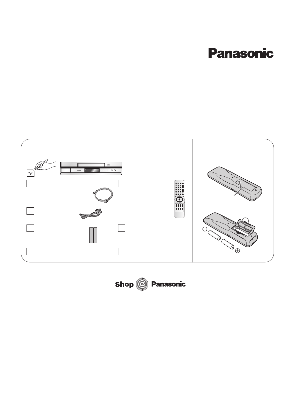
Check List
Check that you have the accessories and items shown
RF cable
K2KF2BA00001, VJA0728-A
or K1TWACC00001
AC Mains lead
RJA0044-3C
Batteries for the
Remote Control
R6 size
Operating Instructions
RQTD0078-B
Remote Control
N2QAKB000044
Quick Start Guide
RQCAD0006 (This leaflet)
Guarantee Card
Fit the Batteries into
the Remote Control
(for UK and Republic of Ireland customers only)
www.panasonic.co.uk
• Order accessory and consumable items for your product with ease and confidence by phoning our Customer Care Centre
Mon–Friday 9:00am–5:30pm. (Excluding public holidays.)
• Or go on line through our Internet Accessory ordering application.
• Most major credit and debit cards accepted
• All enquiries transactions and distribution facilities are provided directly by Panasonic UK Ltd.
• It couldn’t be simpler!
Customer Care Centre
For UK customers: 08705 357357
For Republic of Ireland customers: 01 289 8333
HowtousethisGuide
(1) Connections...............................................................................Pages2–3
(2) AutoSetup................................................................................Pages4–5
RQCAD0006
F10B03-0
-1-
Page 2
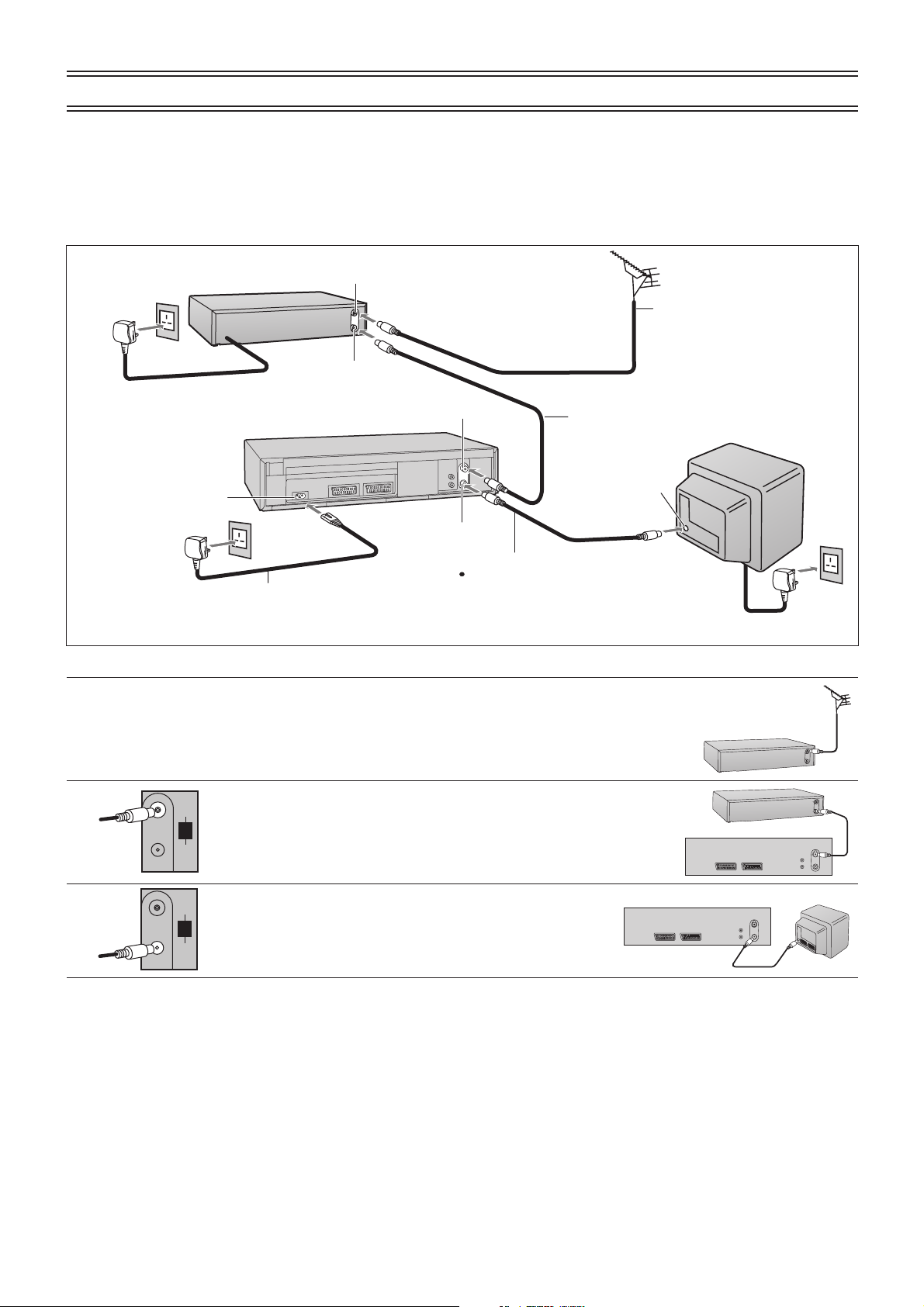
Connections (without Scart cable)
You can connect your VCR to a TV and Satellite Receiver using RF cable.
However, using this connection method it may be difficult to obtain a clear picture from the Satellite Receiver.
For this reason it is not recommended for inexperienced users.
(See preferred connection on page 3.)
Aerial Input socket
Satellite Receiver
Aerial
1
Aerial Output socket
To AC Mains socket
AC Input socket
4
VCR
RF Input socket
RF Output socket
2
RF cable
TV
AerialInput
socket
RF cable (supplied)
Must be connected to
AC Mains lead
(supplied)
1
Connect the aerial to the aerial input socket of the Satellite
4
watch TV channels.
Receiver.
- If you do not have a Satellite Receiver, connect the
3
Satellite Receiver
To AC Mains socket
4
aerial to the RF input socket of the VCR and go to step .3
DEO
2
3
4
IN/
Connect the aerial from the Satellite Receiver to the RF input
ENT
socket.
RF/
ANT
OUT/
SORTIE
IN/
Connect the to the TV aerial socket.Aerial Output socket
ENT
RF/
ANT
OUT/
SORTIE
Plug the TV, VCR and Satellite Receiver into the mains
Satellite Receiver
VCR
VCR
TV
as shown at the top of the page.
Notes:
Switch ON your Satellite Receiver; to ensure reliable tuning select either SKY ONE or SKY NEWS.
If, after Auto Setup is complete, the programme position of the satellite receiver is not to your
preference, or 'SAT' name is not shown in the Programme List, you can re-arrange the
programme position and enter 'SAT' name manually. See page 34-36 of Operating Instruction.
-2-
Page 3

Follow the step-by-step guide below.
AV121-pinScartsocket
AV221-pinScartsocket
AC Input socket
AC Mains lead
6
(supplied)
Satellite Receiver
Connections (with Scart cables)
RF Input socket
RF Output socket
Aerial
VCR
21-pin Scart socket
(VCR)
4
Necessary for connecting
a Satellite Receiver
1
RF cable
2
(supplied)
3
Necessary for TV
Aerial Input
socket
AV2 socket
AV1 socket
TV
6
To AC Ma ins socket
6
To AC Mains socket
1
2
3
4
AV 2(DECODER/DECODEUR/EXT
21-pin Scart socket (TV)
DEO
IN/
ENT
RF/
ANT
OUT/
SORTIE
IN/
ENT
RF/
ANT
OUT/
SORTIE
)
AV 1(TV
)
Optional Connection
5
Connect the aerial to the RF input socket of the VCR.
Connect the RF cable from the RF output socket of the VCR to
the TV aerial input socket.
Connect the AV1 21-pin scart socket to the TV scart socket .
If your TV does not have a scart socket or you do not have a
scart cable, skip this step.
Connect the AV2 21-pin scart socket to the VCR scart socket
on your Satellite Receiver/Digital Receiver. If you are not
connecting a Satellite Receiver, skip this step.
VCR
VCR
VCR
Satellite Receiver
TV
TV
VCR
5
Connect the TV scart socket of your Satellite Receiver to the
Satellite Receiver
TV
AV1 scart socket of your TV. If you are not connecting a
Satellite Receiver, skip this step.
6
Plug the TV, VCR and Satellite Receiver into the mains
as shown at the top of the page.
-3-
Page 4

Auto Setup
1
4
4
4,7
START
EXTLINKEXTLINK
INPUTSELECTINPUTSELECT
PROG PLAYPROGPLAY
AUDIO
CH
PDC
PROG./CHECKPROG./CHECK
OFFTIMER
I-TIMER
INDEX
ENTER
TVASPECT
SP/LP/EP
OSD/DISPLAY
TV/TEXT
TRACKING/V-LOCKTRACKING/V-LOCK
CH
VOLUME
VIDEO Plus+
REC
TIMER
RESET/CANCELRESET/CANCEL
1
VCR
TV
Set the switch to . Turn on the TV, then
press the button to switch on the VCR.
VCR/TV VCR
Standby/ON
The VCR will now start Auto Setup.
!
The first digit of the VCR display will begin to flash.
After a while, it will stop flashing and the RF output
channel number will be displayed.
!
If you have connected the VCR to the TV with a Scart
, you will see the screen on the right during Auto
cable
Setup.
You can skip step below.2
----------------- ---------------- ----------------- -------------- -------------- ----------------- -------------- ------
2
Select an unused channel pre-set on your TV and tune
it to the RF output channel number shown on the VCR
display (or until you can clearly see the Auto Setup
screen shown on the right). Store the new video
playback channel (refer to the instructions for your TV).
If you can see interference on the picture, you may
!
need to change the RF output channel. Follow the
instructions on page 6 to do this.
----------------- ---------------- ----------------- -------------- -------------- ----------------- -------------- ------
3,10
5,8
6,7
5
1
3
4
EXIT
Press the button. The Owner ID screen will appear.
EXIT
You can complete the Owner ID now or skip this step
and do it later. To do it later, press the button
again. Your VCR is now ready to use.
----------------- ---------------- ----------------- -------------- -------------- ----------------- -------------- ------
123
456
7809
To set the Owner ID now, press the
buttons or buttons ( ) to enter a four-digit
Cursor
PIN number.
If you make a mistake, press the button ( ),
Numeric
Cursor
then enter the correct digit. Make sure that you will
remember the PIN number (make a note of it).
----------------- ---------------- ----------------- -------------- -------------- ----------------- -------------- ------
5
ENTER
Press the button and the button ( ).
The cursor moves to [Name].
ENTER Cursor
EXIT
VCR Display
On-Screen Display
Auto-Setup
Tuning : Ch 21
Auto-Setup
VCR Ch : 24
Owner ID
PIN number : 846
*
Name :
**************
House No
:
***********
Postcode
:
***********
You now have the opportunity
to enter your details and
help the police crack crime
see instruction book.
ENTER
: : store
select
EXIT
:
exit
FINISH
Note:
EXIT
----------------- ---------------- ----------------- -------------- -------------- ----------------- -------------- ------
6
----------------- ---------------- ----------------- -------------- -------------- ----------------- -------------- ------
7
Press the button ( ).Cursor
Press the buttons ( ) to select a letter and
then press the button ( ) to move to the next
Cursor
Cursor
letter.
Repeat these steps until you have entered your name.
----------------- ---------------- ----------------- -------------- -------------- ----------------- -------------- ------
8
ENTER
----------------- ---------------- ----------------- -------------- -------------- ----------------- -------------- ------
9
----------------- ---------------- ----------------- -------------- -------------- ----------------- -------------- ------
10
EXIT
Press the button to finish setting your name.ENTER
Enter the [House No] and [Postcode] in the same way.
When you are happy with the information you have
entered, press the button to leave the Owner ID
EXIT
BBC1
screen. You will now see the TV picture.
Your VCR is now ready to use.
!
If Auto Setup has previously been completed, this . In this case you can run
Auto Setup again. See page 37 of Operating Instructions.
!
In some cases, where the VCR has been connected to your TV using the RF cable only (no Scart)
the RF output channel may interfere with the TV stations transmitted in your area.
you from seeing the On-Screen Display clearly. page 6
before restarting Auto Setup (page 37of Operating Instructions)
!
If you want to cancel Auto Setup before it has finished, press the button. You can restart Auto
indication will not appear
This may prevent
Please refer to for removing the interference
.
EXIT
Setup later, see page 37 of Operating Instructions.
-4-
Page 5

Auto Setup
If the clock setting menu appears after Auto Setup has finished (Auto clock set was not possible due to a weak signal)
PROG PLAYPROG PLAY
REC
AUDIO
2
ENTER
1
1
2
ENTER
ENTER
Press the buttons ( ) to set the correct time
Cursor
and date.
Press the button to finish this setting.ENTER
Checking the Settings for Auto Setup
To confirm that the TV Stations have been tuned correctly by Auto Setup
2,3
INPUTSELECTINPUTSELECT
PROG PLAYPROG PLAY
PROG./CHECKPROG./CHECK
I-TIMER
MENU
TVASPECT
EXTLINK
TV/TEXT
TRACKING/V-LOCKTRACKING/V-LOCK
CH
VOLUME
VIDEO Plus+
REC
1
4
INDEX
AUDIO
2,3
ENTER
CH
PDC
SL/LP/EP
TIMER
OFFTIMER
OSD/DISPLAY
RESET/CANCELRESET/CANCEL
1
2
ENTER
3
EXIT
4
Press the button to display the OSD Menu on
MENU
the TV screen.
----------------- ---------------- ----------------- -------------- -------------- ----------------- -------------- ------
Press the buttons ( ) to select [Tuning] then
press the button.
----------------- ---------------- ----------------- -------------- -------------- ----------------- -------------- ------
Press the buttons ( ) to select [Manual] then
press the button to display the list of tuned TV
Cursor
ENTER
Cursor
ENTER
stations and confirm that all available TV stations have
been set correctly. Positions 5 and 6 may differ from the
example shown. If Channel 5 is received, it is usually
found on programme position 5 and a connected
satellite receiver on programme position 6. If Channel 5
is not received but a satellite receiver is connected, then
the satellite receiver is found on programme position 5.
----------------- ---------------- ----------------- -------------- -------------- ----------------- -------------- ------
Press the button to exit the On-Screen Display.EXIT
On-Screen Display
Datum / Zeit
Clock set
MANUAL
Time : 12 : 00 :00
Date : 11. 6. 03
ENTER
ENTER
::
select store
::
wählen
EXIT
MENU EXIT
:
exit
::
zurück abbrechen
speichern
On-Screen Display
Menu
Timer recording
Tuning
Clock set
Others
Tuning
Manual
Auto-Setup
Shipping condition
Owner ID
Tuning
Pos Name Ch Pos Name Ch
1 BBC1 22
2 BBC2 23
3 ITV 24
4 CH4 25
5 CH5 26
List of tuned TV stations
(example)
6 ---- --7
---- ---
8
---- ---
9
---- ---
10
---- ---
Notes:
If the station names and/or channel numbers have not been set correctly.
See page 34 of Operating Instructions for details.
When no stations have been set, confirm all connections and restart Auto Setup.
You can restart Auto Setup, without using remote controller, by pressing some buttons on the front
of the unit. Hold down and on the main unit simultaneously for about 5 seconds.
!
If the station name is [ ]:
The asterisks indicate that Auto Setup found a station but did not assign a name to it (due to a weak signal).
Stations on the list marked by an asterisk will need to be named manually. (See page 35 of Operating Instructions.)
!
If the station name is [----]:
The dashes represent unused channel positions.
Stations on the list marked by dashes will need to be set manually. (See page 34 - 36 of Operating Instructions.).
-5-
Page 6

Removing InterferenceRemoving Interference
TV screen
The picture with interference
TVASPECT
EXTLINK
TV/TEXT
INPUTSELECTINPUTSELECT
PROG PLAYPROG PLAY
TRACKING/V-LOCK
INDEX
AUDIO
CH
VOLUME
VIDEO Plus+
REC
3
3
2
5
ENTER
1
CH
In some cases, interference (lines or patterning) or a very poor picture may appear on the TV when the
VCR is connected. If this happens, follow the steps below to change the video playback channel (RF
output channel) to remove the interference.
VCR
TV
1
MENU
2
Set the switch to .VCR/TV VCR
----------------- ---------------- ----------------- -------------- -------------- ----------------- -------------- ------
Press the button for more than 5 seconds.MENU
The RF output channel number is displayed on the
VCR display.
----------------- ---------------- ----------------- -------------- -------------- ----------------- -------------- ------
3
123
456
7809
Press the buttons or use the buttonNumeric Channel
to select a channel number, which differs by 2 or 3 from
the present channel number. (For example, if the
original channel number was 28, enter 31.)
Set the RF output channel of the VCR to [- -] (RF OFF)
CH
if the VCR is connected to the TV via the 21-pin Scart
cable.
On-Screen Display
VCR Ch:28
Test pattern indication
VCR display
Indication when the RF output
channel is 28 (example)
Press the numeric button or button to0 Channel display
[- -]. Skip step 4, if using a 21-pin Scart cable.
...
21
----------------- ---------------- ----------------- -------------- -------------- ----------------- -------------- ------
4
Retune your TV until you receive the Test pattern. It
may be necessary to repeat steps and above until
(RF OFF)
68
23
Indication after changing the RF
output channel to 31 (example)
VCR Ch:31
you can see the Test pattern clearly.
----------------- ---------------- ----------------- -------------- -------------- ----------------- -------------- ------
5
Press the button to finish this setting.ENTER
Test pattern indication
The clear picture
-6-
 Loading...