


operating Instructions
Video Cassette Recorder
NV-HD1OOEA
VQT5161
SE
PAL
Before attempting to connect, operate or adjust this product,
please read these instructions completely.

Dear Customer
May we take this opportunity to thank you for purchasing this
Panasonic Video Cassette Recorder,
We would particularly advise that you carefully study the
Operating Instructions before attempting to operate the unit and
that you note the listed precautions.

Information for Your Safety
Contents
Setting Up
IMPORTANT
Your attention is drawn to the fact that
recording of pre-recorded tapes ordisce
or other published or broadcast material
may infringe copyright laws.
WARNING
TO REDUCE THE RISK OF FIRE OR
SHOCK HAZARD, DO NOT EXPOSE
THIS EQUIPMENT TO RAIN OR
MOISTURE.
FOR YOUR SAFETY
■ DO NOT REMOVE OUTER COVER.
To prevent electric shock, do not remove
cover. No user serviceable parts inside. Refer
servicing to qualified service personnel.
HQ (High Quality) Picture System
Video recorders carrying the HQ symbol mark feature the
new VHS High Quality Picture System. This system
assures complete compatibility with VTRs that use the
conventional VHS system.
Connections............................................................... 5
Tuning the TV to your VTR
Setting the Clock of the VTR
Storing TV Broadcasts into your VTR
......................................
....................................
.....................
6
7
8
Description
Controls and Connection Sockets
Infra-red Remote Controller ..........
Basic Operations
Playback
On-the-spot Recording
......................
Advanced Operations
Timer Recording
• Using the Remote Controller...................................... 20
Editing
•Assembly Editing......................................................... 22
•Insert Editing
•Audio Dubbing............................................................. 24
Other Functions.......................................................... 25
Bar Code Operation.................................................... 27
•Scanner Preparation
•Setting the Clock........................................................... 28
•Timer Recording ......................................................... 29
........................................................................
..........................................................
..............................................................
...................................................
22
23
27
10
12
14
16
I8
Heipfui Hints
Before Requesting Service
Precautions................................................................. 34
Specifications.............................................................. 35
.......................................
31
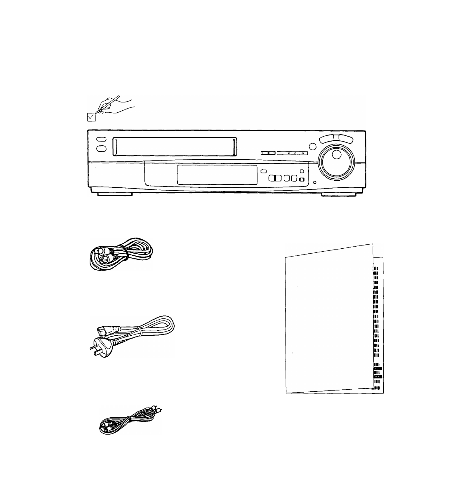
Unpacking
Check and identify the supplied accessories, and then set up this VTR after reading
Setting Up.
□ □
□
□
□
□
KooaJ
Connections Connections c
___________
This tells you how to connect with an aerial, TV, etc.
c
0
Q
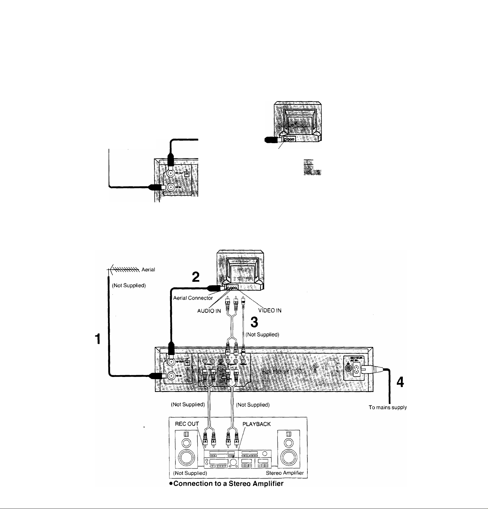
Basic Connections
The following connections are required to record and play
back the VTR through TV set;
Aerial
(Not Supplied)
1
TV Set (Not Supplied)
Aerial Connector
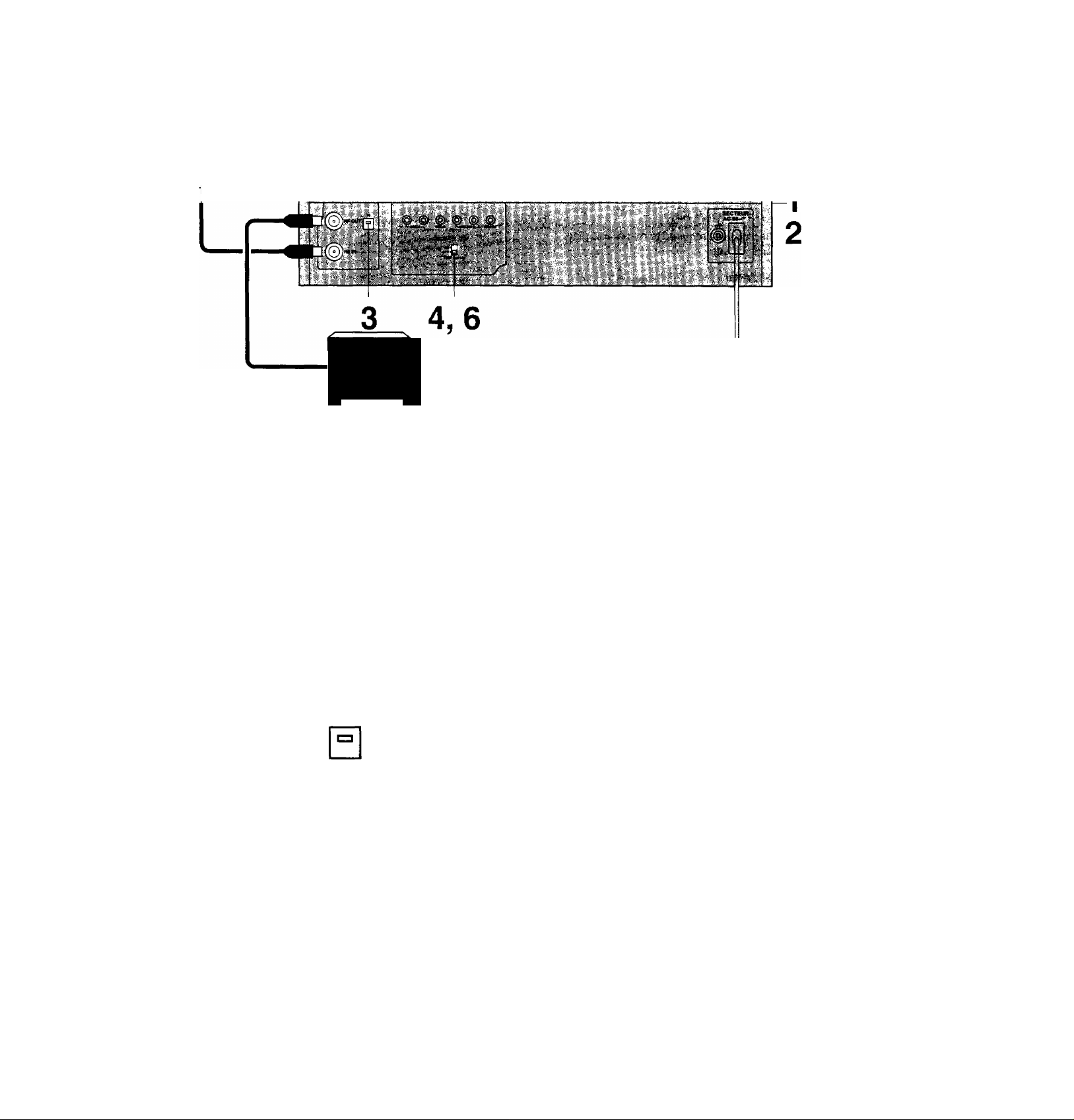
Connection to a TV Set with the Audio/Video Input Sockets
TV Set (Not Supplied)
1
71
To mains supply
Tuning the TV to your VTR
DD
Operations
1
ON-
OFF-
1,5
OPERATE
VTR/
TV
o
H
It is possible to view the video picture on your TV in the
same way that you watch TV broadcasts.
If you have connected the VTR to the TV through the.
video and audio input sockets then you do not need to
follow the procedure mentioned below.
Display Symbols
Turn on the TV and VTR.
Select the VTR mode.
VTR
Select the video playback channel which is
not occupied with any TV station.
H; Channel 3
L: Channel 2
To generate a test pattern, set TEST
SIGNAL to ON.
TEST SIGNAL
ID
ON-
OFF'
□
TEST SIGNAL
Set the TV to an unused position which you
wish to use for your video playback.
H: Channel 3
L Channel 2
Set TEST SIGNAL to OFF.
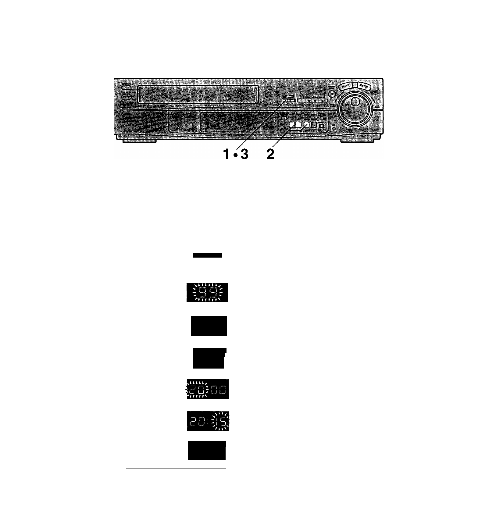
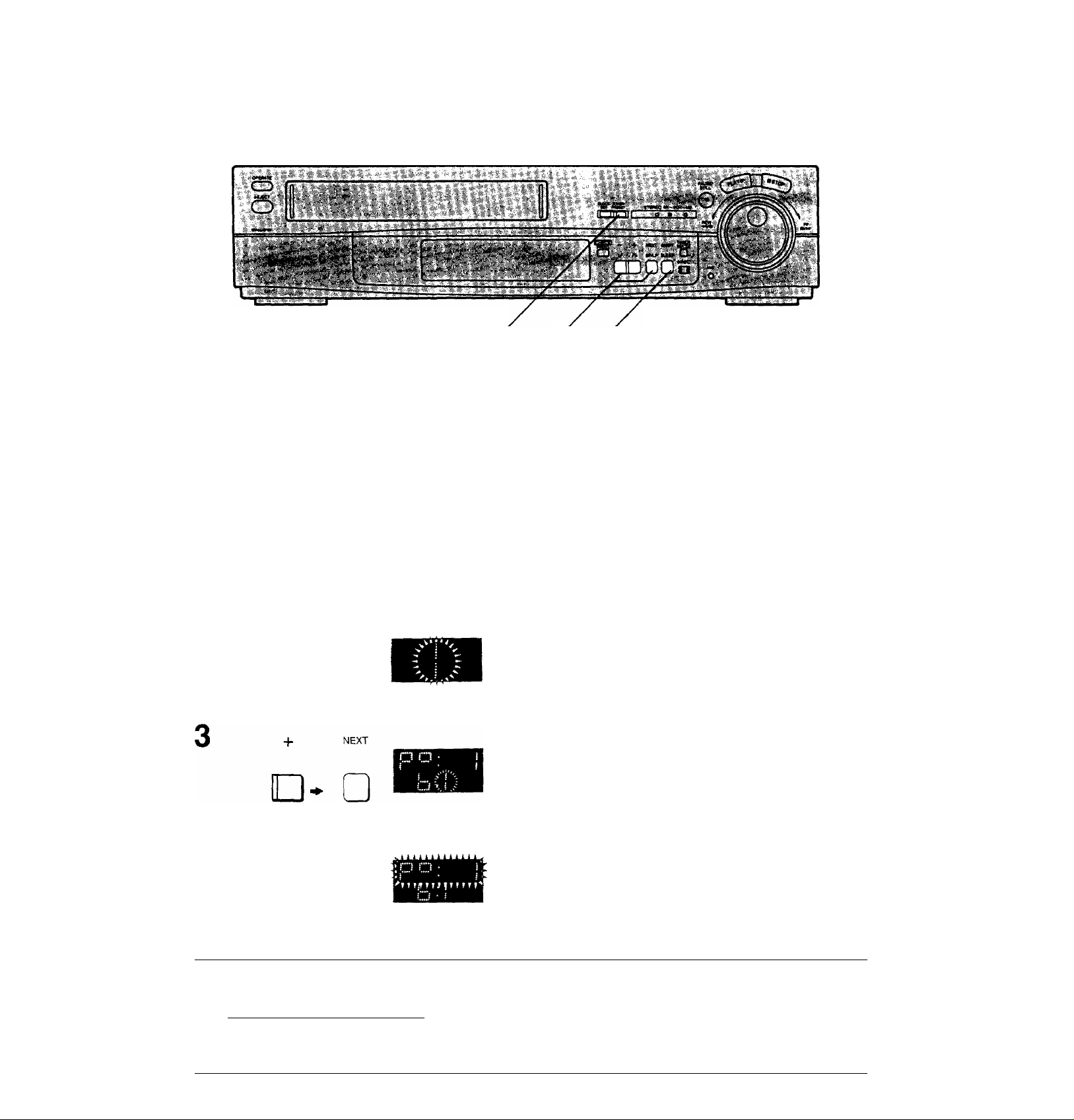
Setting the Clock of the VTR
The built-in clock is used to activate the tinner for automatic
recording and must be set to the correct time.
The built-in digital clock employs the 24-hour system.
Tuning the TV to your VTR
Setting the Clock of the VTR
C
.C
0:
cr
I
Preparation
Turn on the VTR.
Operations
CLOCK
1
SET
Display Symbols
CZD T ? T ?
2 Set each item by pressing + or - and NEXT.
“ +
Z I • *Z
^ ? I....- ^
» T fI
^kkkkkk^
^ r'
^ * '•***
-- ?
T T r r
For Example:
Date; 16th, October, 1999
Time; 20:15
Keep CLOCK SET pressed for more than
2 seconds.
Set Year “99”.
Set Month “10”.
Set Date “16”.
NEXT
□
CLOCK
SET
( II
Note;
The clock operates for at least 60 minutes by its backup
system in the event of power failure.
■~i rh
_j j i ■
{ i ! •
U LJ i .j:
S i”"
? i
i ”1
Set Hour “20”.
Set Minute “15”.
•There is no need to press NEXT,
Press CLOCK SET.
•The clock will start.
Time reset function
XX'.OO.OO can be set by performing the operation steps 1
and 3 during XX;58.00-XX;01.59.
storing TV Broadcasts into your VTR
1.52-44
Introduction
The VTR is fitted with its own tuner (just like a normal TV
set) and can be pre-set to receive up to 99 TV broadcast
stations.
Operations
1
TUNER
PRESET
Display Symbols
□ZD
- +
NEXT
]- □
Preparation
•Confirm that the TV is on and the VTR viewing channel is
selected.
•Turn on the VTR and press VTR/TV to select the VTR
mode.
•Turn on the VTR and select the programme position
except A1.
Keep TUNER PRESET pressed for more
than 2 seconds.
Select the programme position,
then press NEXT.
Select TV band “I”, ‘‘m”or “U”,
then press NEXT.
5
- +
TUNER
PRESET
rri
] □
SHIFT
Search for the required TV station by
pressing and holding + or
Release once the station has been found.
•Search speed changes quickly by pressing SHIFT
simultaneously with -f or
•Press NEXT and repeat steps 2-4 for each programme
position you want to tune to a station.
Press TUNER PRESET twice.

Fine Tuning Procedure
1 Keep TUNER PRESET pressed for more than
2 seconds, and then press again.
2 Press NEXT.
3 Press + or - to obtain the best tuning condition.
•“AFC" Indicator disappears.
•To return the tuning to its former state, press SHIFT.
4 Press TUNER PRESET.
Storing TV Broadcasts into your VTR
a
0
1
Blanking of Unoccupied Programme Positions
1 Keep TUNER PRESET pressed for more than
2 seconds.
2 Select a programme position which you do not want to
tune to a TV station, by using + or —.
3 Press SHIFT. {“—’’ is displayed.)
• Repeat steps 2 and 3 for other unoccupied programme
positions to skip during the selection of the programme
positions.
•To cancel the blanking of a programme position, select
that programme position on the VTR and then press
SHIFT.
4 Press TUNER PRESET twice.
Channel Plan
1 UHF
21-69
1-3
VHF '' ^ .
4-11
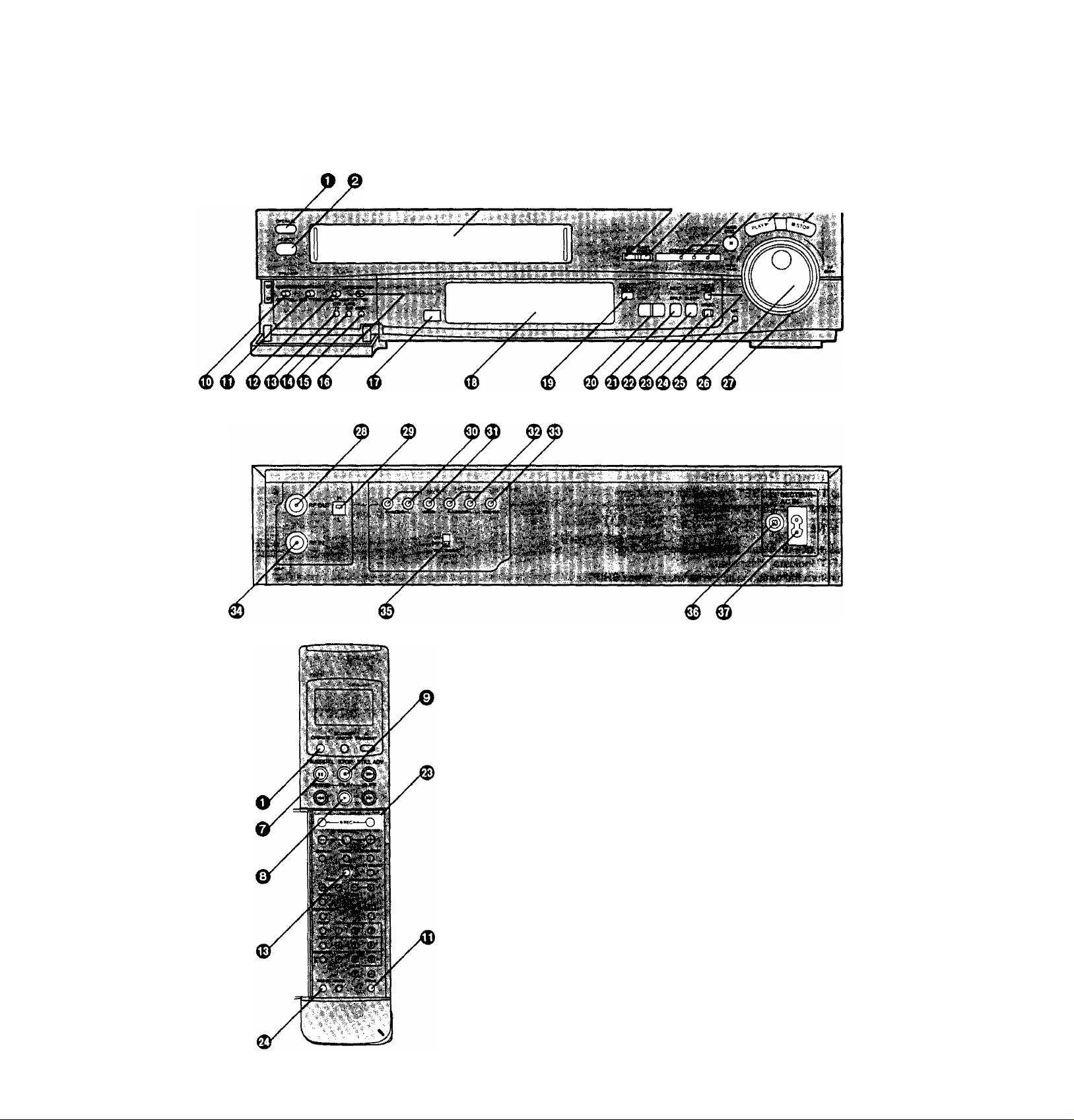
Controls and Connection Sockets
This gives a detailed explanation of the function of each button, switch and connection socket.
o OPERATE
To turn the VTR on and off.
0 EJECT
To eject a video cassette.
e Cassette Compartment
Insert a video cassette here.
©CLOCK SET
To set the time,
0 TUNER PRESET
To initiate TV station settings for the tuner.
© Indicator Lamps for Ml, M2 and Stereo Reception
When receiving a TV programme, automatically
indicates when a TV programme is broadcast with the
NICAM sound system.
o PAUSE/STILL
During playback; Still picture.
During recording; To interrupt recording.
In the stop mode: Still picture. (Only VTR)
0 PLAY
To start playback. is lit.
0 STOP
To stop any playback or recording.
to

0 NOISE FILTER
OFF: For normal VTR operation.
ON: For playback of a cassette whose recording
quality is inferior.
® REMOTE MODE (VTR 1/2)
VTR 1: Set at this position on both the VTR and
remote controller for normal use with one VTR.
VTR 2: Set at this position when using two Panasonic
VTRs.
This allows the remote controller to be set for
operating VTR 1 or VTR 2,
0 NICAM/MONO
NICAM: Normally set at this position.
MONO: Only set at this position to record the normal
sound during a NfCAM broadcast or if the
stereo sound is distorted due to inferior
reception conditions.
© VTR/TV
To select the VTR mode or TV mode.
© AUDIO DUB
To set up the VTR for audio dubbing.
A.DUB indicator lights up.
© INSERT
To set up the VTR for insert editing.
INSERT indicator lights up.
© Hi-Fi/NORMAL MIX
OFF: Normally set at this position to reproduce the
better sound available from the Hi-Fi track.
ON: Both sound tracks are played back mixed
together. Use this setting when playing back a
cassette tape which has been insert edited or
audio dubbed.
0 Infra-red Remote Control Receiver Window
© Display
0 CHECK/PROG
To select a timer programme number.
"1,2,3... or 8’’is lit.
To display details of preset timer recording.
© -+/ V A
To set the clock and timer recording.
To select the required programme position {TV
station).
0 NEXT/SP/LP
To proceed to the next item during setting procedure.
To select the tape speed required for recording.
SP gives the best picture quality.
LP gives the longest recording time.
Controls and Connection Sockets
® SHIFT/SLEEP
To blank unoccupied programme position.
To set the time to turn off the VTR automatically.
® REC
To start a recording.
0 TIMER REC
To turn the timer recording function on and off.
B is lit or not lit.
The VTR can only be operated manually when the
timer recording function is off.
© MIC
To connect a microphone for recording.
This socket has priority.
© Jog Dial
To locate any desired frame with utmost precision.
0 Shuttle Ring
In the stop mode: To rewind or fast forward the tape.
In the playback mode:
To search picture backward or
forward.
In the still playback mode:
To adjust playback speed backward
or forward.
In the rewind or fast forward mode:
To obtain high speed picture.
© RFOUT
To connect to the aerial terminal on a TV set.
Video Playback Channel Selector
To select the video playback channel.
© AUDIO IN
To connect the audio cable to a video camera or
another video recorder.
0 VIDEO IN
To connect the video cable to a video camera or
another video recorder.
© AUDIO OUT
To connect the audio cable to a TV or another video
recorder.
© VIDEO OUT
To connect the video cable to a TV or another video
recorder.
© RFIN
To connect to the external aerial.
© TEST SIGNAL
The test signal is transmitted on channel L or H.
© Signal Ground Terminal
To connect the Signal Ground Terminal to the ground
to reduce the noise from microphone cable.
C
,c
•i
c
c
I
© ACIN--
To connect to the main power supply.
11
 Loading...