

SI
■■^*' éNggi "4§in0^^ ^'‘“®
' ■ ■. •■ :--i
:*S
-i#S|p
i' f
'ti^- m
'Ì-9fÙ’y''^^P^X!
VHS
Video Cassette Recorder
}i]d°Fd H Q
PAL
NV-H65Series
HNational
Before attempting to connect, operate or adjust this product, please read these instructions completely.
VQT2140

page
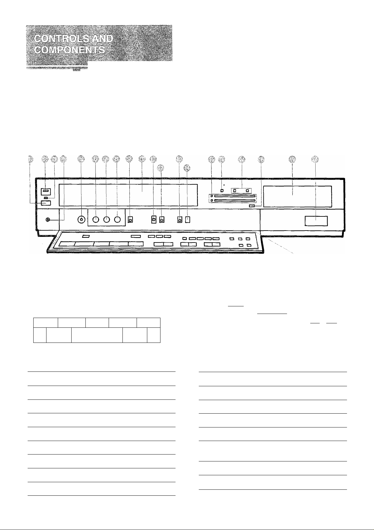
4 CONTROLS AND COMPONENTS
7 FEATURES
8 INSTALLATION
9 TUNING THE TV SET TO THE VIDEO PLAYBACK CHANNEL
10 SETTING THE CLOCK TO THE PRESENT TIME
12 SETTING THE TUNER IN THE VTR
13 THE VIDEO CASSETTE
14 PLAYBACK
17 RECORDING FROM A TV BROADCAST SIGNAL
18 HI-FI AUDIO SYSTEM
19 SUPER OTR FUNCTION (ONE-TOUCH TIMER RECORDING)
21 TIMER RECORDING
24 CAMERA RECORDING
25 DUBBING (COPYING)
26 USING THE NV-H65 AS A HI-FI AUDIO RECORDER
27 PROGRAMMABLE REMOTE CONTROLLER (INFRA-RED)
28 BEFORE REQUESTING SERVICE
30 CAUTIONS
31 SPECIFICATIONS
IMPORTANT
Your attention is drawn to the fact that
recording of pre-recorded tapes or discs or
other published or broadcast material may
infringe copyright laws.
FOR YOUR SAFETY
B DO NOT REMOVE OUTER COVER.
To prevent electric shock, do not remove cover.
No user serviceable parts inside. Refer servicing
to qualified service personnel.
WARNING
TO PREVENT FIRE OR SHOCK HAZARD,
DO NOT EXPOSE THIS EQUIPMENT TO
RAIN OR MOISTURE.
NV-H65A: Australian model
NV-H65EA; New Zealand model
NV-H65BA: South African mode)
is the safety information.
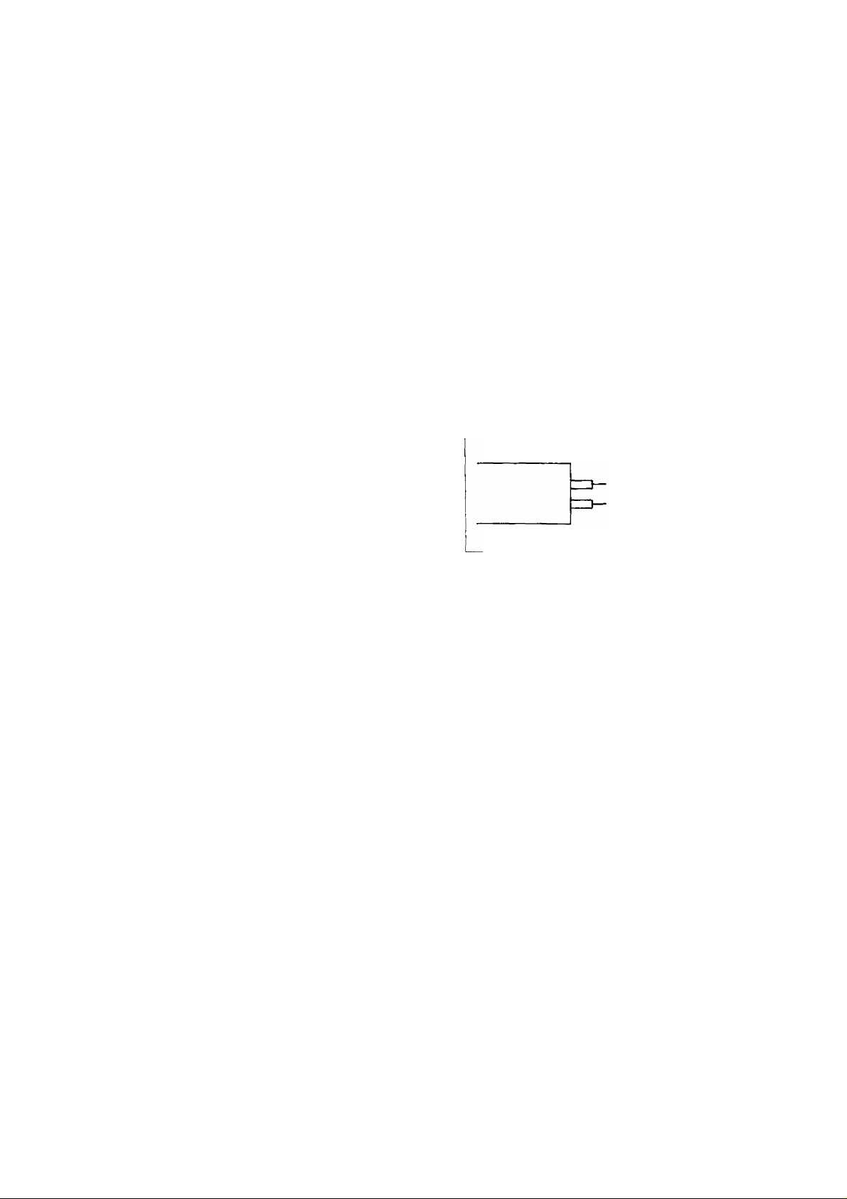
fl AC MAINS LEAD CONNECTION. (NV-H65BA)
The wires in the mains lead of this apparatus are
coloured in accordance with the following code.
Important
BLUE
.........
NEUTRAL
BROWN ............... LIVE
Mains Lead
As the colours of the wires in the mains lead may not
correspond with the coloured markings identifying the
terminals in your plug proceed as follows: The wire
which is coloured BLUE must be connected to the
terminal which is marked with the letter N or coloured
BLACK. The wire which is coloured BROWN must be
connected to the terminal which is marked with the
letter L or coloured RED.
'■ ■ :
■ v>>7r\ .;■■■■ ■
...
i/ii."“’'”;-'
RECO ESEH0 MEMORY R^ET
D [ZZDdZKZIZI
DD
Page No.
No.
REW/0
<)<
-------------
PLAY-
Description
p>
-©/FF
»
STOP PAUSE/STILL
p
Eject Button (^) 13
VTR On/Off Switch/lndicator 9
’-■■j.;' Cassette-in Indicator 13
./¿¡L Headphones Socket
Headphones Output Level Control
; Tracking Control
Slow Tracking Control
Picture Sharpness Control
7 7.; Edit Switch
18
18
14
15
14
25
reÌe
taiigga
CLOCK PROG
- +
□ CZ3
+ NEXT
ir ic: i!
- -!I
____
I
Description Page
; 7 Cassette Compartment
'i " Audio Level Meter Selector
iii MPX Filter Switch
: i. Input Signal Selector
Timer Record Button
^i:;j Audio Level/Hi-Fi Tracking Meter &
Audio Playback Mode indicators
ID Simulcast Indicator
iD Audio Recording Mode Indicators (NV-H65A)
START BAND CLEAR
n □ n
OFF AFC
[" SEARCH--'^
7 ^
I-FINE TUNING-f
m
13
14
26
18
22
5
18
18
No. Description
Page
No. Description
Page
Control Panel Open Button
Multi Function Display
III? Infra-red Remote Control Receiver
^ Audio Playback Mode Selector
iU Record Button (@) 17
gi VTR/TV Selector (NV-H65A, EA) 9
CU Memory/Search Lock Button
U; Reset Button
Ui' Timer Controls
70 Multi Function Display
:j \é)
10
27
18
16
14
10
^ Rewind ◄◄/Review Q Button
5
^ Play Button (►)
^ Fast Forward ►►-/Cue © Button
Stop Button (B)
^ Pause/Still Button (1B) 15
■fCl Channel Selection Up and Down Buttons
^ OTR On Buttons
OTR Off Buttons
$0} Tuner Set-up Controls 12
14
14
14
16
12
20
19
U Ul
ILI ul
REC
COUNT
CU)
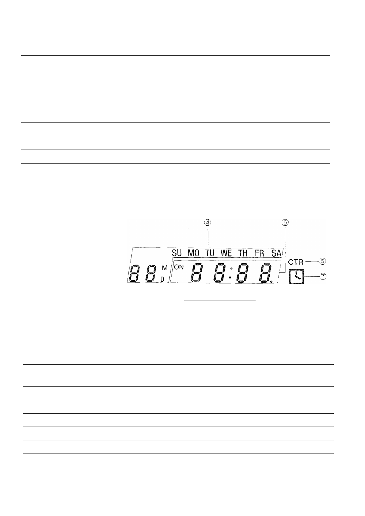
No. Description Page
(U Recording Indicator 17
® VTR Indicator (NV-H65A, EA)
C3/ Channel Display
® Date Display
9
12
10 i m) Tape Counter Indicator 16
2
-M /off
3 4 5 6
W
U ^ W • U JJ Uì
LI ^ HI ^ LK \U ul
_ U ^ When dew forms:
07 U Dew Indicator
No. Description
(8) Timer Programme Number 21
(9; Tape Counter Display 16
Uj) Search Lock indicator
3)
Page
16
® Clock Display
{§) OTR indicator
QT Timer Recording Display
10 'U) Memory Indicator
19
22
70 Tape Running Display
14
14
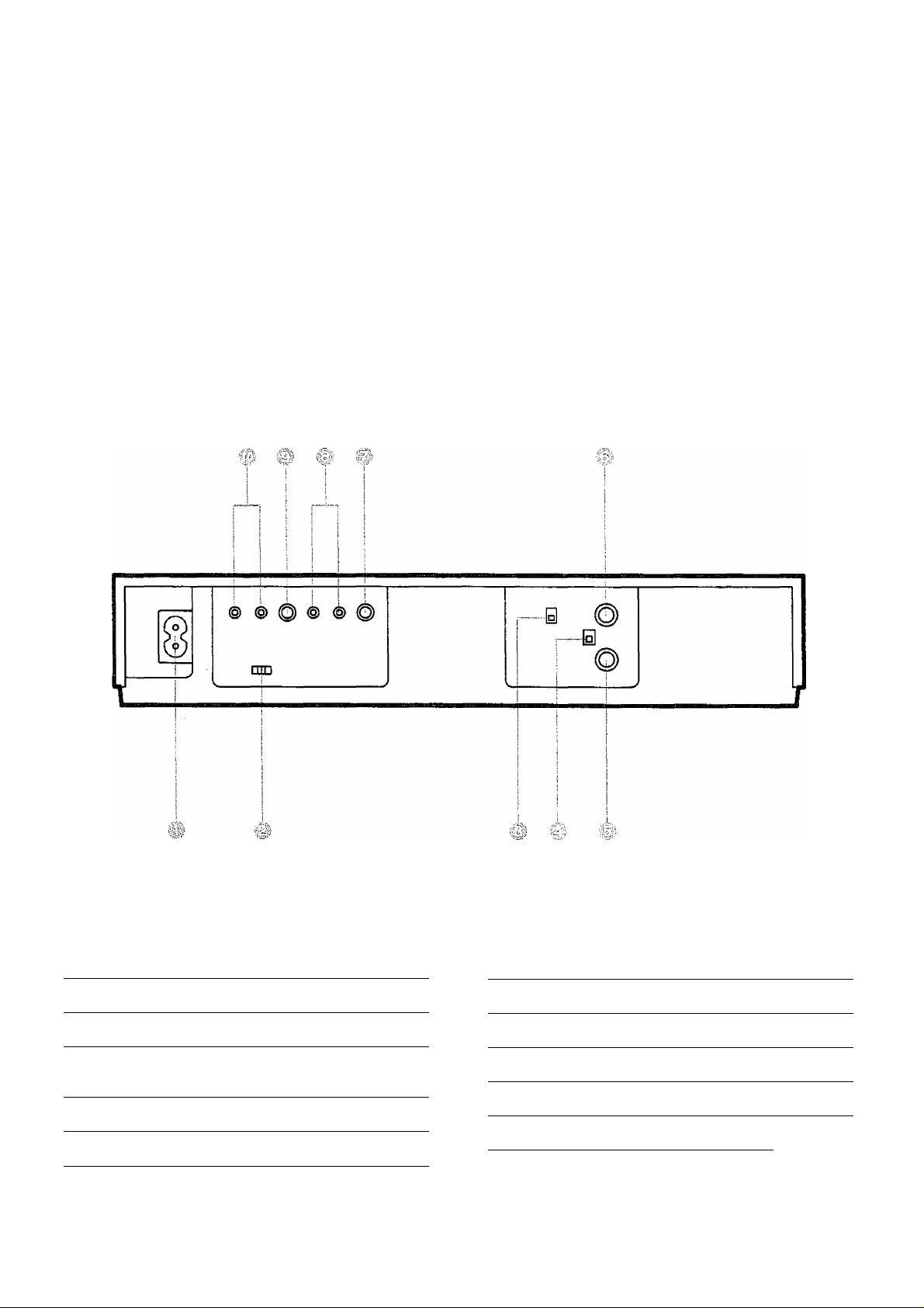
No. Description
Page
No. Description Page
AC Mains Input Socket
Colour Mode/Test Signal Switch
RF Converter Channel Selector
(NV-H65A, EA)
RF Signal Level Switch
" RF Input Socket 8
8
9
9
9
RF Output Socket
Video Output Socket
Audio Output Sockets 8
.'|i Video Input Socket 24
Audio Input Sockets
25
8
8

This unit is equipped with an Automatic Voltage Selector.
The unit can be used where the local voltage indication is
between 110-240 V, without any manual voltage adjust
ment.
This highly functional design allows loading the video
cassette from the front, thus minimizing the space required
for the placement.
The revolutionary newly developed hi-fi stereo recording
system features two rotary audio heads arranged on the
video head cylinder and an FM conversion recording
method. The result of this innovative system is superb
sound quality with a dynamic range of 90 dB, wide
frequency response from 20 Hz to 20 kHz and 0.005% wow
and flutter.
The excellent audio quality, outstanding tape economy,
continuous 4-hour audio recording capability and Audio
Rec Level Meter make this VTR ideal for use as a
top-quality audio cassette recorder.
This VTR allows recording and playback of the stereo
sound of TV programmes broadcast via "Simulcast” by
connecting an FM tuner to the Audio Input Sockets.
The new Hi-Fi stereo system in combination with the built-in
multiplex tuner can process audio two-channel as well as
monaural signals for both recording and playback. Even if
the TV set used is of the mono type, stereo or bilingual
sound of recorded programmes or sound of TV pro
grammes,- being received on the VTR tuner and played
back through the TV set can be reproduced via a connected
hi-fi stereo system with external speakers.
The clock/timer of the NV-H65 is programmed with the
calendar up to the end of 2001, so it knows exactly what
day of the week it is on any given date. Programming of as
many as 8 timer recordings is possible up to one month in
advance.
This VTR automatically turns itself on when a video
cassette is inserted even if it .was turned off. When the tab
of the inserted cassette is broken out, playback will start
automatically. Also, even if the VTR is off when the Eject
Button is pressed, it automatically turns itself on to eject the
cassette tape and it turns itself off again.
When a video cassette tape with a broken out tab is
inserted and the VTR is switched over to recording, OTR or
timer recording, the cassette tape will be automatically
ejected.
When the tape reaches its end (except during OTR and
timer recording), it will automatically rewind to the begin
ning.
If the VTR On/Off button is pressed during the rewind
mode including Auto Rewind, the VTR will eject the
cassette and turn itself off when rewinding is completed.
Super Still, Super Still Advance and Super Fine Slow
Playback are possible with superb picture quality with
minimum noise and jitter.
The built-in tuner in this VTR allows pre-tuning of as many
as 16 TV stations. So this VTR can accommodate virtually
any increase in available TV programmes in the future.
Whenever an operation button is pressed, the activated
function is immediately Indicated on this easy-to-see
display. It shows you at a glance, in what operation mode
the VTR is functioning.
The new Lap Time Counter is a great improvement over
the approximate counter systems of conventional VTRs. It
gives you an exact reading of the elapsed tape time in
hours, minutes and seconds, and makes it easy to calculate
the tape time left on a cassette, (up to ±4:00.00)
This convenient function makes it possible to easily
programme the VTR for recording of TV programmes with
immediate start or with start within 24 hours and with the
starting time and ending time precisely set to the desired
minute. When the recording ends, the VTR will automatical
ly turn itself off.
In addition to letting you control all major VTR functions, this
handy Remote Controller also lets you programme timer
recordings from the comfort of your armchair.
Video recorders carrying the HQ symbol mark feature the
new VHS High Quality Picture System. This system
assures complete compatibility with VTRs that use the
conventional VHS system.
«When listening to a radio while the VTR is in operation, the
radio reception may be distorted. In this case, move the
radio away from the VTR.
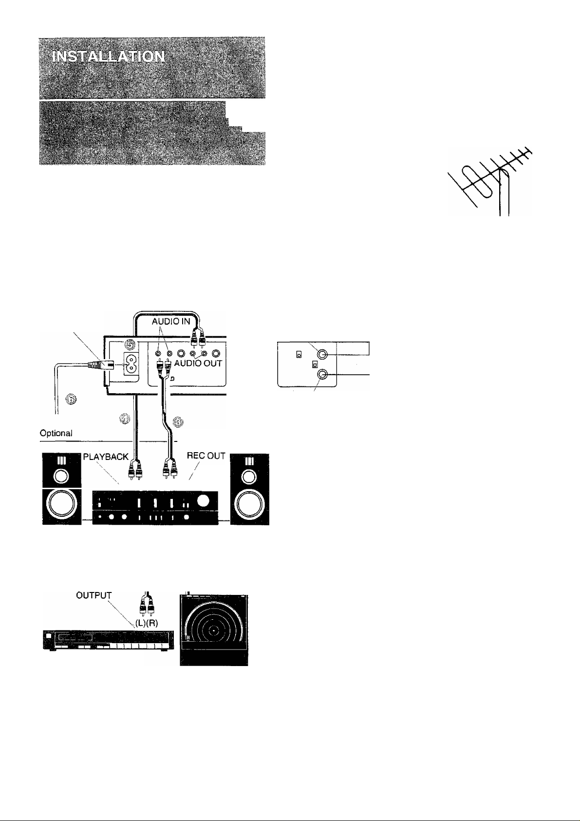
AC Mains Lead
(Supplied)
Stereo Cable (Supplied)
Stereo
,(L)(R) (L)(R)/Amplifier
Optional
RFOUT
\
TV Set
To the Aerial Socket
\
RFIN
NV-H65A:
FOR YOUR SAFETY
Install any external aerial to AS 1417.1.
DIN-DIN Coaxial Cable
Optional
(Supplied)
il
Speaker (L) ^/(L)(R) (L)(R)'\ Speaker (R)
TUNER
FM Stereo Tuner
Record Player
PHONO
Connect the external aerial to the RF Input Socket on
the VTR.
# Connect the aerial terminal on your TV set to the RF
Output Socket on the VTR with the supplied DIN-DIN
Coaxial Cable.
^ Connect the Audio Input Sockets on the VTR to the
Stereo Amplifier REC OUT Sockets.
Connect the Audio Output Sockets on the VTR to the
PLAYBACK Sockets on the Stereo Amplifier.
Connect the AC Mains Lead to the AC Mains Socket of
the VTR.
■ Connect the AC Mains Lead to the mains outlet.
8
® ® o ® ® ©
COLOUR/TEST SIGNAL
COLOUR '
AUTO-
jT] -TEST
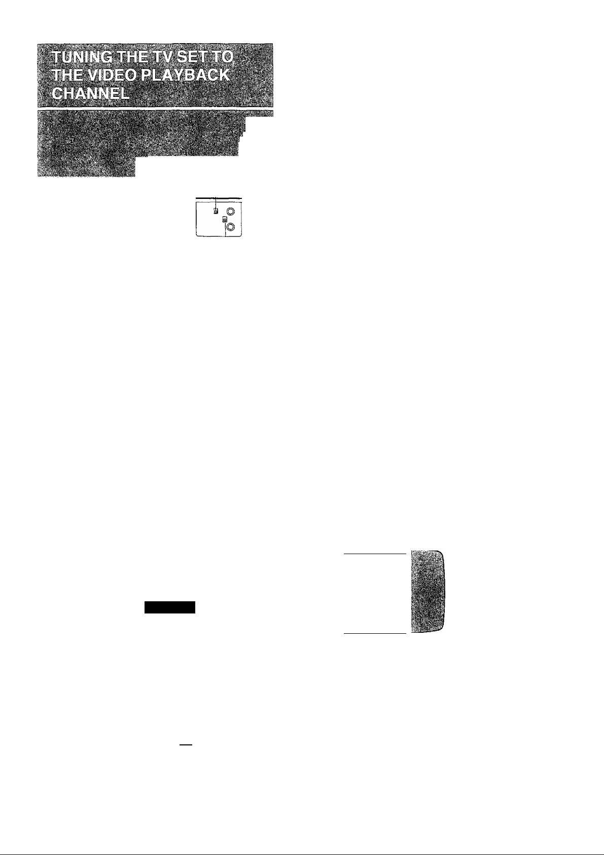
i|5l Turn the TV set on and select the AV programme
position or another programme position that is not
occupied by any TV station.
^ Press the VTR On/Off Switch to turn the VTR On.
^
(FRONT SIDE)
VTR
•The corresponding indicator lights up.
RF Converter Channel Selector. (NV-H65A, EA)
This switch is used to select the RF channel which is not
occupied with any TV station, {NV-H65A: 0 or 1;
NV-H65EA: 2 or 3.)
-RF Signal Level Switch;
Used to attenuate the reception of the VHF and/or UHF
aerial signals. If the reception is normal, set to “HIGH”. If
the signal is strong (stripes appear in the upper part of the
picture), set to “LOW”.
Tune the selected programme position (channel) of the
TV set to the VHF or UHF channel shown below for
your model. Confirm on the TV set that the received
test pattern is as shown below.
NV-H65A VHF channel 0 or 1* *
NV-H65EA VHF channel 2 or 3
NV-H65BA UHF channel 36
10 Press the VTR/TV Selector to “VTR" position.
The NV-H65BA is not equipped with this selector.
------------------------------------------------------------------------
VTR/TV
©VTR Indicator will appear in the Multi-Function
Display.
ill Set the Colour Mode/Test Signal Switch to “TEST”.
COLOUR/TEST SIGNAL
COLOUR i
AUTO-
m - TEST
(REAR SIDE)
NV-H65A only
*ln some areas chan
-
iSi;
nel 0 may be used by
local TV station. In
this case switch to
channel 1.
.V'<; !
V'l
Set the Colour Mode/Test Signal Switch to “AUTO”.
Your TV is now ready to receive the RF output signal
from the VTR.
—
COLOUR/TEST SIGNAL
COLOUR
AUTO
TEST
m
©If, during recording or playback, the colour is not
satisfactory, it can be stabilized by setting Colour
Mode/Test Signal Switch to COLOUR.
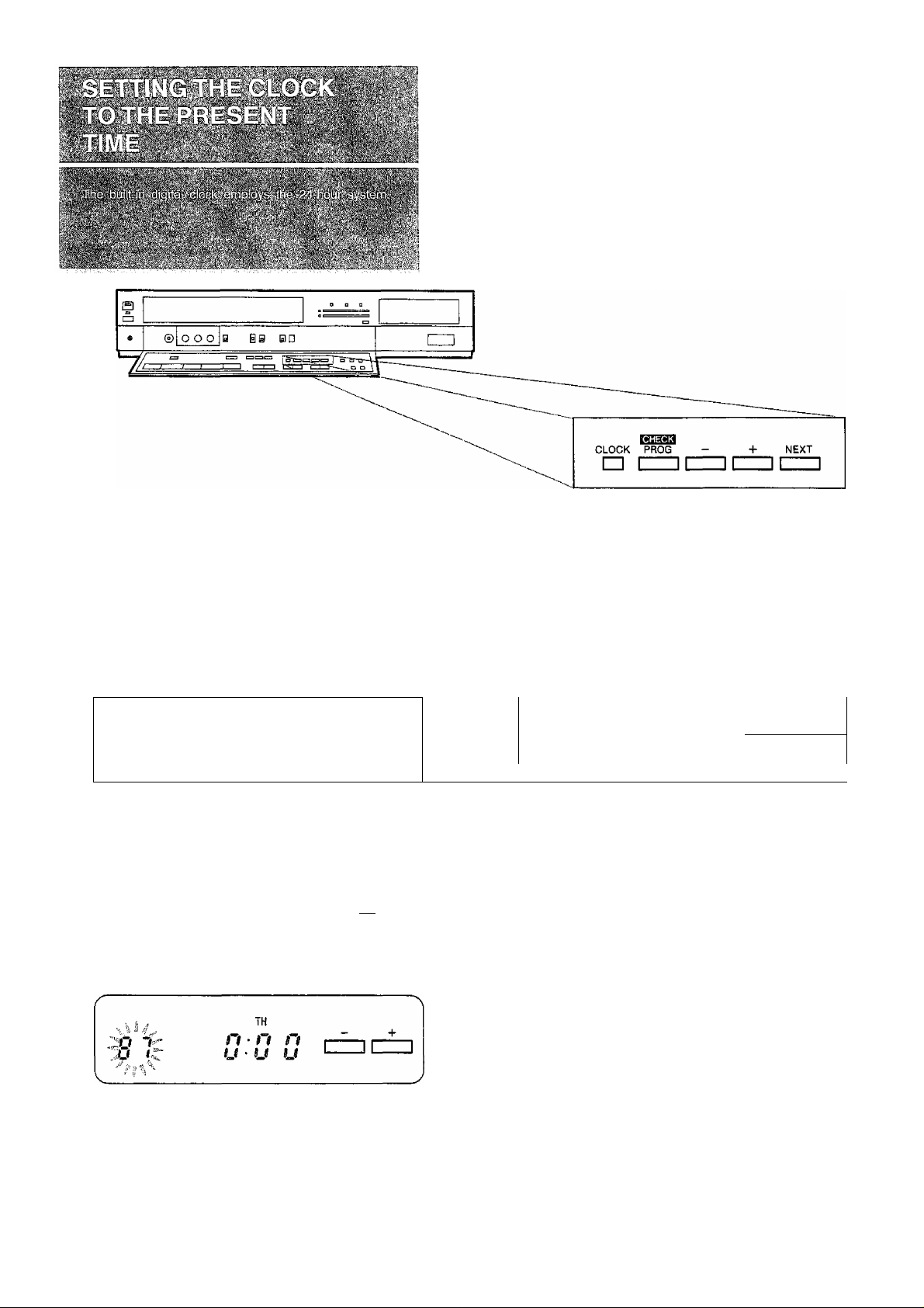
•Connect the VTR to the mains outlet.
•Press the VTR On/Off Switch to turn the VTR On.
•Press the Control Panel Open Button.
When connecting this VTR to the mains or after a long
power failure, both the date and time indications flash.
k k k ii
-S3 o c
^ KJ u
y V i f M V
Press the Clock Button to start the date and time
setting.
—
^ CC
io Q
Press the {+) or (-) Button to set the year.
kkkkkkkkI L/
WE
n • n
U • U
!???!ff?
WE
n • n Tf
n z
u L
u • u u
CLOCK
r~l
|| Press the (+) or (-) Button to set the month.
TH
n
u
V
_______________
n • n
u • u
t!l Press the Next Button.
TH
I V
i
Press the (+) or (-) Button to set the day.
'-'i ri'C
n • n n
u • u u
SA
n • n n
u ■ u u
— +
1
_____IL______
NEXT
1
J
'IS Press the Next Button.
,ra t
TH
n • 11 n
U * U U
NEXT
CZZ]
10
Press the Next Button.
i n
i u D
' I t^n n
u/ru u
SA
NEXT
 Loading...