

panasonic NV-GX7EG, NV-GX7EGM, NV-GX7B, NV-GX7EN, NV-GX7A Service Manual
...
gx7eg_v1.html
Table Of Contents
COVER
1 INTRODUCTION
1.1 INTRODUCTION
1.2 FEATURE
COMPARISON CHART
2 CAUTION FOR AC
CORD (VJA0940 TYPE)
2.1 INFORMATION FOR
YOUR SAFETY
2.2 CAUTION FOR AC
MAINS LEAD
2.2.1 Important
2.2.2 Before use
2.2.3 How to replace the Fuse
3 SERVICE CAUTION
3.1 HOW TO DISCHARGE
THE CAPACITOR ON
FRONT C.B.A.
3.2 EEPROM DATA FOR
SPARE PARTS OF THE
MAIN C.B.A.
3.3 SERVICE EXTENSION
CABLES
3.4 LOCATION FOR
SPARE CONNECTORS OF
THE MAIN C.B.A.& SUB C.B.
A.
3.4.1 MAIN C.B.A.
3.4.2 SUB C.B.A.
4 PREPARATION FOR
ELECTRICAL
ADJUSTMENT
5 SERVICE MODE
5.1 New Error Code Display
5.2 Viewing Error Code
6 HOW TO REPLACE THE
Service Manual
TOP NEXT
ORDER NO.VMD0204025C8
Digital Video Camera/Recorder
● NV-GX7EG/NV-GX7EGM/NV-GX7B/NV-GX7EN/NV-GX7A/NV-GX7ENT
VOL.1
Q3-MECHANISM
Forum Tec
: 972 9 7964119, ª972 68 645477, : 972 9 7965674
|: forum@go4.co.il
http://202.224.189.178/~sgml/viewing/NV-GX7EG/EUOT/SVC/PVAccel.html (1 of 4)17/02/2004 10:36:28
gx7eg_v1.html
LITHIUM BATTERY
(PROCEDURE)
7 OPERATING GUIDE
8 ADJUSTMENT
PROCEDURES
8.1 DISASSEMBLE FLOW
CHART
8.2 DISASSEMBLY
PROCEDURES
8.3 DISASSEMBLY
PROCEDURES OF CAMERA
LENS UNIT
9 ABBREVIATIONS
10 WAVEFORM TABLE
11 SCHEMATIC
DIAGRAMS
11.1 OVERALL
SCHEMATIC DIAGRAM
11.2 INTERCONNECTION
SCHEMATIC DIAGRAM
11.3 CCD FLEX. CARD
SCHEMATIC DIAGRAM
11.4 SIDE (L) SCHEMATIC
DIAGRAM
11.5 CASSETTE COVER
UNIT SCHEMATIC
DIAGRAM
11.6 REAR OPERATION
UNIT SCHEMATIC
DIAGRAM
11.7 MAIN FRAME UNIT
(CASSETTE DOWN FLEX.
CARD) SCHEMATIC
DIAGRAM
11.8 SIDE (R)& LCD DET
SCHEMATIC DIAGRAM
11.9 FLASH FLEX. UNIT
SCHEMATIC DIAGRAM
© 2002 Matsushita Electric Industrial Co., Ltd. All rights reserved. Unauthorized copying and distribution is a violation of law.
TOP NEXT
http://202.224.189.178/~sgml/viewing/NV-GX7EG/EUOT/SVC/PVAccel.html (2 of 4)17/02/2004 10:36:28

gx7eg_v1.html
11.10 EVF SCHEAMTIC
DIAGRAM
11.11 FRONT& MIC UNIT
SCHEMATIC DIAGRAM
11.12 JACK SCHEMATIC
DIAGRAM
11.13 MONITOR& HALL
SENSOR FLEX. SCHEMATIC
DIAGRAM
12 CIRCUIT BOARD
ASSEMBLIES
12.1 CCD FLEX. CARD C.B.
A.
12.2 SIDE (L) C.B.A.
12.3 SIDE (R) C.B.A.
12.4 FRONT C.B.A.
12.5 JACK C.B.A.
12.6 MONITOR C.B.A.
12.7 EVF C.B.A.
12.8 LCD DET C.B.A.
13 EXPLODED VIEWS
13.1 FRAME& CASING
SECTION (1)
13.2 FRAME& CASING
SECTION (2)
13.3 LCD SECTION
13.4 CAMERA LENS
SECTION
13.5 PACKING PARTS&
ACCESSORIES SECTION
14 REPLACEMENT PARTS
LIST
14.1 FRAME& CASING
SECTION (1) PARTS LIST
14.2 FRAME& CASING
SECTION (2) PARTS LIST
PV
PV
http://202.224.189.178/~sgml/viewing/NV-GX7EG/EUOT/SVC/PVAccel.html (3 of 4)17/02/2004 10:36:28

gx7eg_v1.html
14.3 LCD SECTION PARTS
LIST
14.4 CAMERA LENS
SECTION PARTS LIST
14.5 PACKING PARTS&
ACCESSORIES SECTION
PARTS LIST
14.6 ELECTRICAL
REPLACEMENT PARTS
LIST
15 SCHEMATIC DIAGRAM
FOR PRINTING WITH A4
SIZE
http://202.224.189.178/~sgml/viewing/NV-GX7EG/EUOT/SVC/PVAccel.html (4 of 4)17/02/2004 10:36:28

http://202.224.189.178/~sgml/viewing/NV-GX7EG/EUOT/SVC/gx7eg_v1.html
Table Of Contents
COVER
1 INTRODUCTION
1.1 INTRODUCTION
1.2 FEATURE COMPARISON CHART
2 CAUTION FOR AC CORD (VJA0940 TYPE)
2.1 INFORMATION FOR YOUR SAFETY
2.2 CAUTION FOR AC MAINS LEAD
2.2.1 Important
2.2.2 Before use
2.2.3 How to replace the Fuse
3 SERVICE CAUTION
3.1 HOW TO DISCHARGE THE CAPACITOR ON FRONT C.B.A.
3.2 EEPROM DATA FOR SPARE PARTS OF THE MAIN C.B.A.
3.3 SERVICE EXTENSION CABLES
3.4 LOCATION FOR SPARE CONNECTORS OF THE MAIN C.B.A.& SUB C.B.A.
3.4.1 MAIN C.B.A.
3.4.2 SUB C.B.A.
4 PREPARATION FOR ELECTRICAL ADJUSTMENT
http://202.224.189.178/~sgml/viewing/NV-GX7EG/EUOT/SVC/gx7eg_v1.html (1 of 4)17/02/2004 10:36:29

http://202.224.189.178/~sgml/viewing/NV-GX7EG/EUOT/SVC/gx7eg_v1.html
5 SERVICE MODE
5.1 New Error Code Display
5.2 Viewing Error Code
6 HOW TO REPLACE THE LITHIUM BATTERY (PROCEDURE)
7 OPERATING GUIDE
8 ADJUSTMENT PROCEDURES
8.1 DISASSEMBLE FLOW CHART
8.2 DISASSEMBLY PROCEDURES
8.3 DISASSEMBLY PROCEDURES OF CAMERA LENS UNIT
9 ABBREVIATIONS
10 WAVEFORM TABLE
11 SCHEMATIC DIAGRAMS
11.1 OVERALL SCHEMATIC DIAGRAM
11.2 INTERCONNECTION SCHEMATIC DIAGRAM
11.3 CCD FLEX. CARD SCHEMATIC DIAGRAM
11.4 SIDE (L) SCHEMATIC DIAGRAM
11.5 CASSETTE COVER UNIT SCHEMATIC DIAGRAM
11.6 REAR OPERATION UNIT SCHEMATIC DIAGRAM
11.7 MAIN FRAME UNIT (CASSETTE DOWN FLEX. CARD) SCHEMATIC DIAGRAM
http://202.224.189.178/~sgml/viewing/NV-GX7EG/EUOT/SVC/gx7eg_v1.html (2 of 4)17/02/2004 10:36:29

http://202.224.189.178/~sgml/viewing/NV-GX7EG/EUOT/SVC/gx7eg_v1.html
11.8 SIDE (R)& LCD DET SCHEMATIC DIAGRAM
11.9 FLASH FLEX. UNIT SCHEMATIC DIAGRAM
11.10 EVF SCHEAMTIC DIAGRAM
11.11 FRONT& MIC UNIT SCHEMATIC DIAGRAM
11.12 JACK SCHEMATIC DIAGRAM
11.13 MONITOR& HALL SENSOR FLEX. SCHEMATIC DIAGRAM
12 CIRCUIT BOARD ASSEMBLIES
12.1 CCD FLEX. CARD C.B.A.
12.2 SIDE (L) C.B.A.
12.3 SIDE (R) C.B.A.
12.4 FRONT C.B.A.
12.5 JACK C.B.A.
12.6 MONITOR C.B.A.
12.7 EVF C.B.A.
12.8 LCD DET C.B.A.
13 EXPLODED VIEWS
13.1 FRAME& CASING SECTION (1)
13.2 FRAME& CASING SECTION (2)
13.3 LCD SECTION
PV
http://202.224.189.178/~sgml/viewing/NV-GX7EG/EUOT/SVC/gx7eg_v1.html (3 of 4)17/02/2004 10:36:29

http://202.224.189.178/~sgml/viewing/NV-GX7EG/EUOT/SVC/gx7eg_v1.html
13.4 CAMERA LENS SECTION
13.5 PACKING PARTS& ACCESSORIES SECTION
14 REPLACEMENT PARTS LIST
14.1 FRAME& CASING SECTION (1) PARTS LIST
14.2 FRAME& CASING SECTION (2) PARTS LIST
14.3 LCD SECTION PARTS LIST
14.4 CAMERA LENS SECTION PARTS LIST
14.5 PACKING PARTS& ACCESSORIES SECTION PARTS LIST
14.6 ELECTRICAL REPLACEMENT PARTS LIST
15 SCHEMATIC DIAGRAM FOR PRINTING WITH A4 SIZE
http://202.224.189.178/~sgml/viewing/NV-GX7EG/EUOT/SVC/gx7eg_v1.html (4 of 4)17/02/2004 10:36:29
http://202.224.189.178/~sgml/viewing/NV-GX7EG/EUOT/SVC/s0000000000.html
Service Manual
TOP NEXT
ORDER NO.VMD0204025C8
Digital Video Camera/Recorder
● NV-GX7EG/NV-GX7EGM/NV-GX7B/NV-GX7EN/NV-GX7A/NV-GX7ENT
VOL.1
Q3-MECHANISM
http://202.224.189.178/~sgml/viewing/NV-GX7EG/EUOT/SVC/s0000000000.html (1 of 2)17/02/2004 10:36:29
http://202.224.189.178/~sgml/viewing/NV-GX7EG/EUOT/SVC/s0000000000.html
© 2002 Matsushita Electric Industrial Co., Ltd. All rights reserved. Unauthorized copying and distribution is a violation of law.
TOP NEXT
http://202.224.189.178/~sgml/viewing/NV-GX7EG/EUOT/SVC/s0000000000.html (2 of 2)17/02/2004 10:36:29

http://202.224.189.178/~sgml/viewing/NV-GX7EG/EUOT/SVC/s0100000000x.html
1 INTRODUCTION
TOP PREVIOUS NEXT
1.1 INTRODUCTION
1.2 FEATURE COMPARISON CHART
TOP PREVIOUS NEXT
http://202.224.189.178/~sgml/viewing/NV-GX7EG/EUOT/SVC/s0100000000x.html17/02/2004 10:36:30

http://202.224.189.178/~sgml/viewing/NV-GX7EG/EUOT/SVC/s0101000000.html
1.1 INTRODUCTION
TOP PREVIOUS NEXT
This service manual contains technical information which will allow service personnel´s to understand
and service this model.Please place orders using the parts list and not the drawing reference numbers.
If the circuit is changed or modified, this information will be followed by supplement service manual to
be filed with original service manual.
Information for Q-Mechanism should be referd to the another manual as below.
Order No. : VMD0109026C8
Note 1:
These movie cameras use AC Adaptor is VSK0581-A.
The service manual for AC Adaptor is separate volume.
Order number for AC Adaptor ..........VSK0581-A : VMD0105013C8
Note 2:
1) This service manual does not contain the following information, because of the impossibility of
sevicing at component level.
1. Schematic Diagram, Block Diagram and C.B.A. layout of Main C.B.A./ Sub C.B.A.
2. Parts List for individual parts of Main C.B.A./ Sub C.B.A.
3. Exploded View and Parts List for individual parts of Mechanism Unit.
2) The following category is/are recycle module part. Please send it/them to Central Repair Center.
*Main C.B.A. (VEP03G17K)
*Sub C.B.A. (VEP23567B)
http://202.224.189.178/~sgml/viewing/NV-GX7EG/EUOT/SVC/s0101000000.html (1 of 2)17/02/2004 10:36:30

http://202.224.189.178/~sgml/viewing/NV-GX7EG/EUOT/SVC/s0101000000.html
When a part replacement is required for repairing each Main C.B.A. and/ or Mechanism block, replace
the assembly parts.
(Main C.B.A., Sub C.B.A. and/ or Mechanism Unit)
The following circuits are contained in Main C.B.A.
1. Main Connection Circuit
2. Drive Circuit
3. Video 1 Circuit
4. Video 2 Circuit
5. Control Circuit
6. LCD Circuit
7. Head/ Rec Amp Circuit
8. Power Circuit
The following circuits are contained in Sub C.B.A.
1. Sub Connection Circuit
2. Camera Circuit
3. Lens Drive Circuit
4. Ex Input Circuit
5. DSC Circuit
6. SD Audio Circuit
TOP PREVIOUS NEXT
http://202.224.189.178/~sgml/viewing/NV-GX7EG/EUOT/SVC/s0101000000.html (2 of 2)17/02/2004 10:36:30
http://202.224.189.178/~sgml/viewing/NV-GX7EG/EUOT/SVC/s0102000000.html
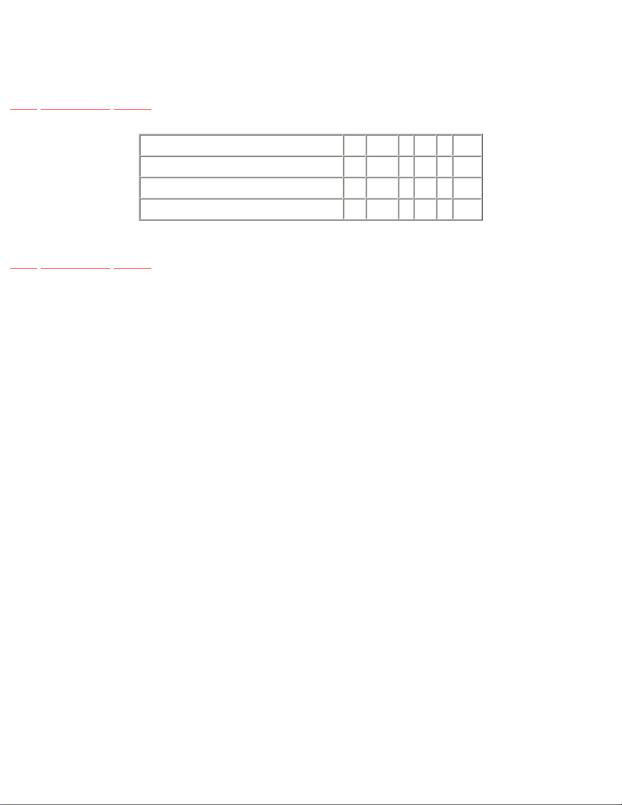
1.2 FEATURE COMPARISON CHART
TOP PREVIOUS NEXT
FUNCTION EG EGM B EN A ENT
Card Function (Multi Media Card, SD Card) • • • • • •
External DV/ VIDEO Input • • • • • •
MPEG4 Recording • • • • • •
TOP PREVIOUS NEXT
http://202.224.189.178/~sgml/viewing/NV-GX7EG/EUOT/SVC/s0102000000.html17/02/2004 10:36:31

http://202.224.189.178/~sgml/viewing/NV-GX7EG/EUOT/SVC/s0200000000x.html
2 CAUTION FOR AC CORD (VJA0940 TYPE)
TOP PREVIOUS NEXT
2.1 INFORMATION FOR YOUR SAFETY
2.2 CAUTION FOR AC MAINS LEAD
2.2.1 Important
2.2.2 Before use
2.2.3 How to replace the Fuse
TOP PREVIOUS NEXT
http://202.224.189.178/~sgml/viewing/NV-GX7EG/EUOT/SVC/s0200000000x.html17/02/2004 10:36:32

http://202.224.189.178/~sgml/viewing/NV-GX7EG/EUOT/SVC/s0201000000.html
2.1 INFORMATION FOR YOUR SAFETY
TOP PREVIOUS NEXT
IMPORTANT
Your attention is drawn to the fact that recording of pre-recorded tapes or discs or other published or
broadcast material may infringe copyright laws.
WARNING
To reduce the risk of fire or shock hazard, do not expose this equipment to rain or moisture.
CAUTION
To reduce the risk of fire or shock hazard and annoying interference, use the recommended accessories
only.
FOR YOUR SAFETY
DO NOT REMOVE THE OUTER COVER
To prevent electric shock, do not remove the cover. No user serviceable parts inside. Refer servicing to
qualified service personnel.
TOP PREVIOUS NEXT
http://202.224.189.178/~sgml/viewing/NV-GX7EG/EUOT/SVC/s0201000000.html17/02/2004 10:36:32
http://202.224.189.178/~sgml/viewing/NV-GX7EG/EUOT/SVC/s0202000000.html
2.2 CAUTION FOR AC MAINS LEAD
TOP PREVIOUS NEXT
For your safety, please read the following text carefully.
This appliance is supplied with a moulded three-pin mains plug for your safety and convenience.
A 5-ampere fuse is fitted in this plug.
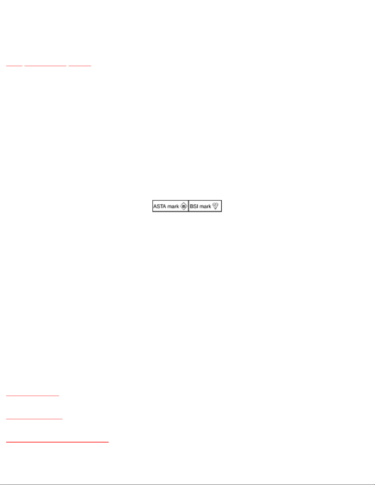
Should the fuse need to be replaced please ensure that the replacement fuse has a rating of 5 amperes
and it is approved by ASTA or BSI to BS1362
Check for the ASRA mark or the BSI mark on the body of the fuse.
If the plug contains a removable fuse cover you must ensure that it is refitted when the fuse is replaced.
If you lose the fuse cover, the plug must not be used until a replacement cover is obtained.
A replacement fuse cover can be purchased from your local Panasonic Dealer.
If the fitted moulded plug is unsuitable for the socket outlet in your home then the fuse should be
removed and the plug cut off and disposed of safety.
There is a danger of severe electrical shock if the cut off plug is inserted into any 13-ampere socket.
If a new plug is to be fitted please observe the wiring code as shown below.
If in any doubt, please consult a qualified electrician.
2.2.1 Important
2.2.2 Before use
2.2.3 How to replace the Fuse
http://202.224.189.178/~sgml/viewing/NV-GX7EG/EUOT/SVC/s0202000000.html (1 of 2)17/02/2004 10:36:33

http://202.224.189.178/~sgml/viewing/NV-GX7EG/EUOT/SVC/s0202000000.html
TOP PREVIOUS NEXT
http://202.224.189.178/~sgml/viewing/NV-GX7EG/EUOT/SVC/s0202000000.html (2 of 2)17/02/2004 10:36:33
http://202.224.189.178/~sgml/viewing/NV-GX7EG/EUOT/SVC/s0202010000.html
2.2.1 Important
TOP PREVIOUS NEXT
The wires in this mains lead are coloured in accordance with the following code:
Blue Neutral
Brown Live
As the colours of the wires in the mains lead of this appliance may not correspond with the coloured
markings identifying the terminals in your plug, proceed as follows:The wire which is coloured BLUE
must be connected to the terminal in the plug which is marked with the letter N or coloured BLACK.The
wire which is coloured BROWN must be connected to the terminal in the plug which is marked with the
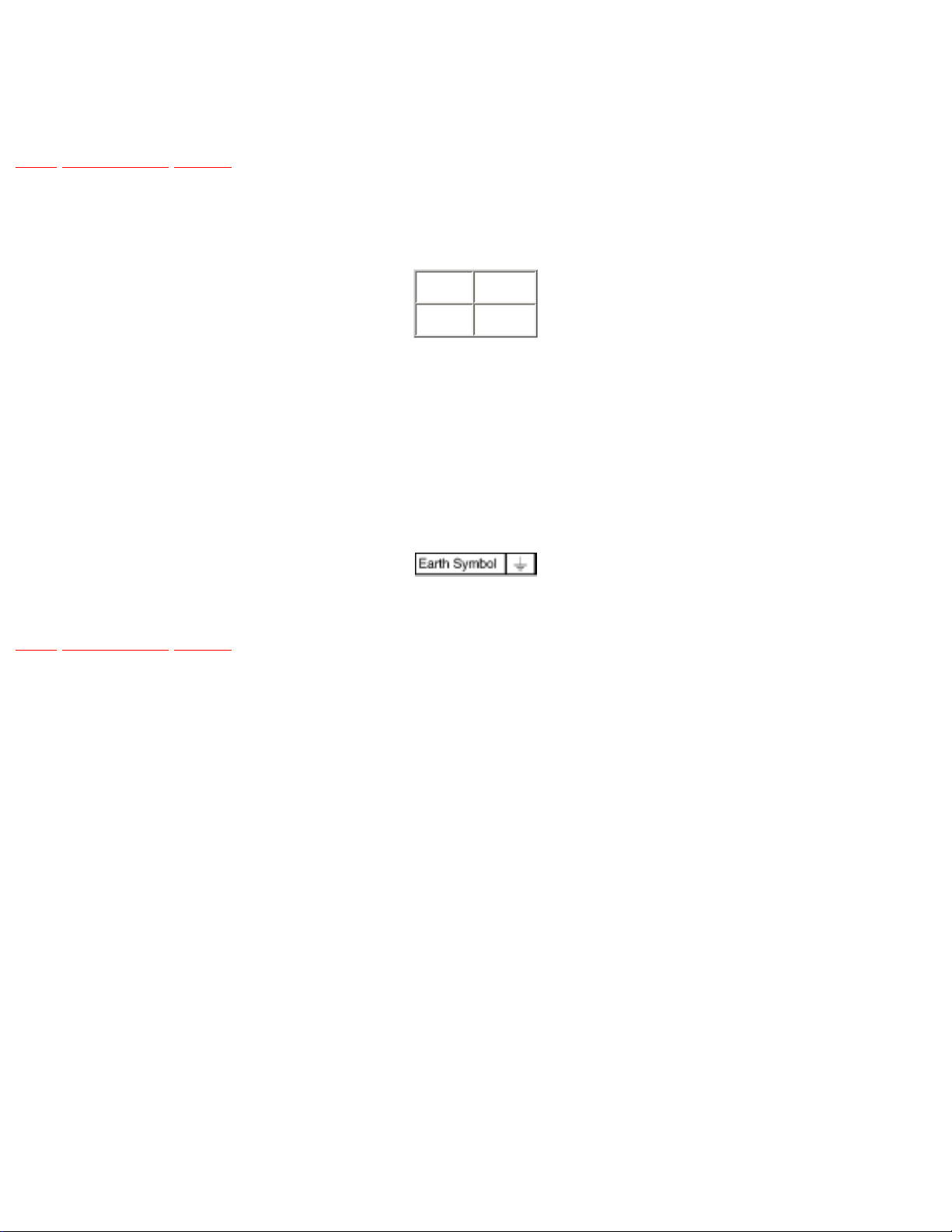
letter L or coloured RED.Under no circumstances should either of these wires be connected to the earth
terminal of the three pin plug, marked with the letter E or the Earth Symbol.
TOP PREVIOUS NEXT
http://202.224.189.178/~sgml/viewing/NV-GX7EG/EUOT/SVC/s0202010000.html17/02/2004 10:36:34
http://202.224.189.178/~sgml/viewing/NV-GX7EG/EUOT/SVC/s0202020000.html
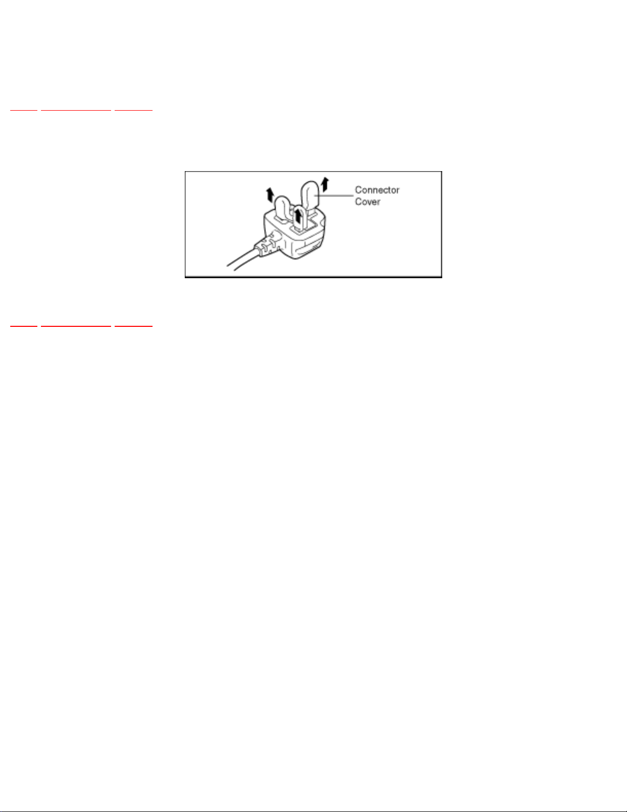
2.2.2 Before use
TOP PREVIOUS NEXT
remove the Connector Cover as follows.
TOP PREVIOUS NEXT
http://202.224.189.178/~sgml/viewing/NV-GX7EG/EUOT/SVC/s0202020000.html17/02/2004 10:36:35
http://202.224.189.178/~sgml/viewing/NV-GX7EG/EUOT/SVC/s0202030000.html
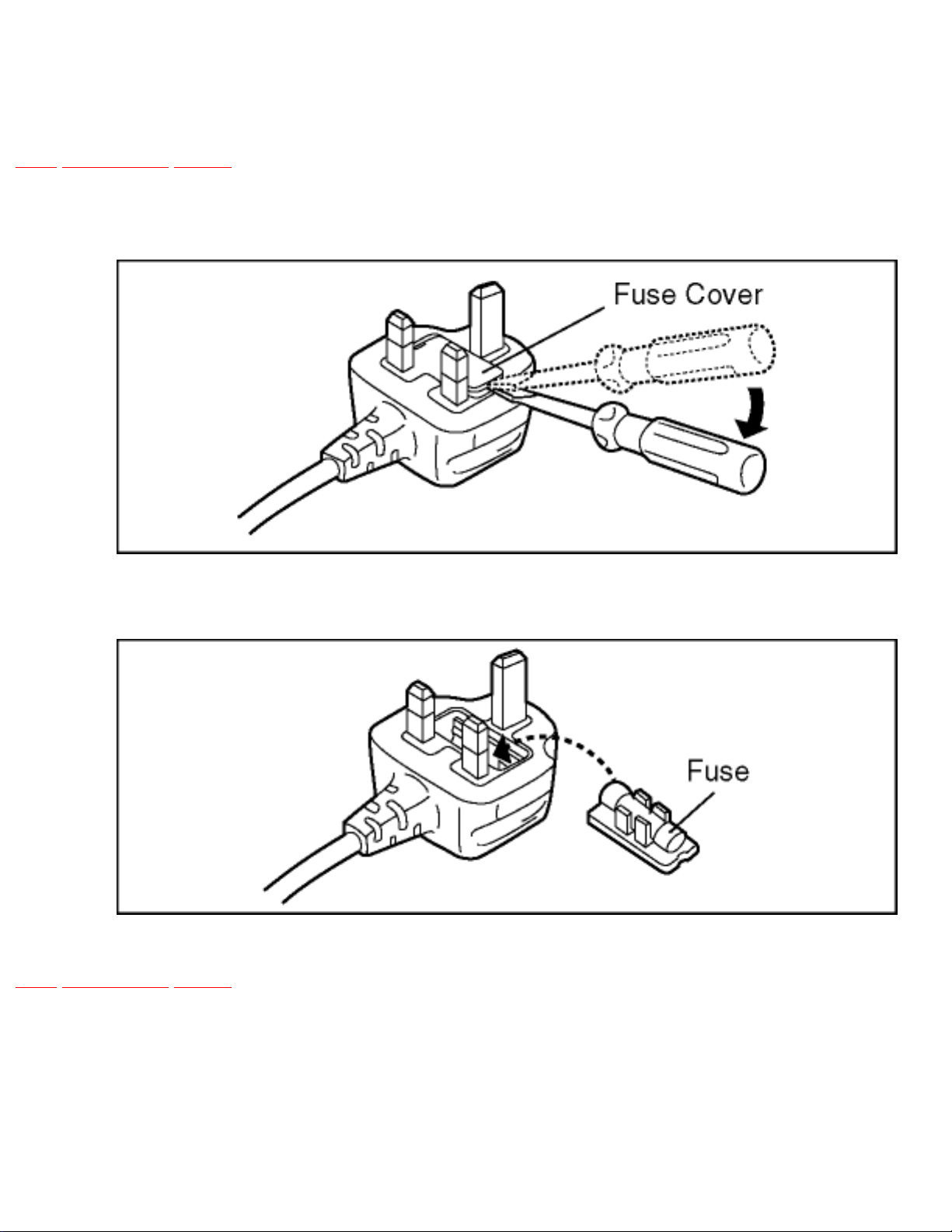
2.2.3 How to replace the Fuse
TOP PREVIOUS NEXT
1. Remove the Fuse Cover with a screwdriver.
2. Replace the fuse and attach the Fuse cover.
TOP PREVIOUS NEXT
http://202.224.189.178/~sgml/viewing/NV-GX7EG/EUOT/SVC/s0202030000.html17/02/2004 10:36:37

http://202.224.189.178/~sgml/viewing/NV-GX7EG/EUOT/SVC/s0300000000x.html
3 SERVICE CAUTION
TOP PREVIOUS NEXT
3.1 HOW TO DISCHARGE THE CAPACITOR ON FRONT C.B.A.
3.2 EEPROM DATA FOR SPARE PARTS OF THE MAIN C.B.A.
3.3 SERVICE EXTENSION CABLES
3.4 LOCATION FOR SPARE CONNECTORS OF THE MAIN C.B.A.& SUB C.B.A.
3.4.1 MAIN C.B.A.
3.4.2 SUB C.B.A.
TOP PREVIOUS NEXT
http://202.224.189.178/~sgml/viewing/NV-GX7EG/EUOT/SVC/s0300000000x.html17/02/2004 10:36:37
http://202.224.189.178/~sgml/viewing/NV-GX7EG/EUOT/SVC/s0301000000.html
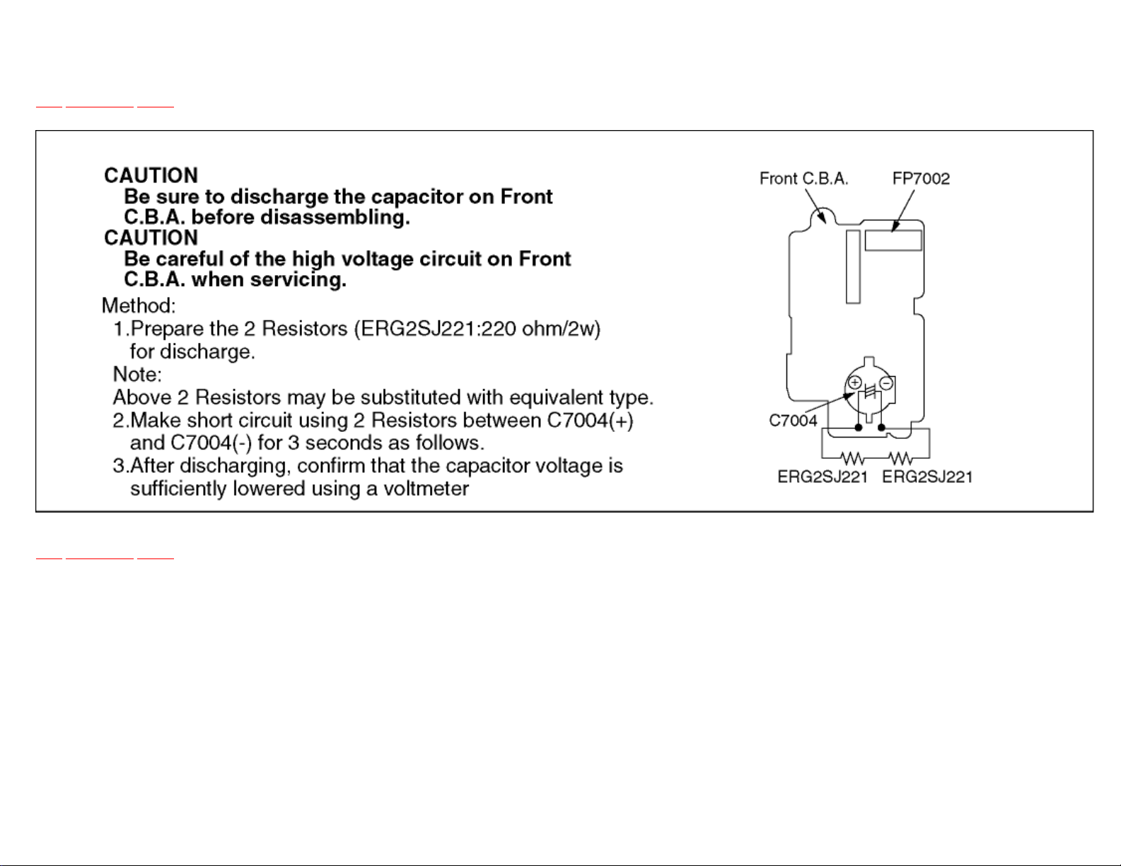
3.1 HOW TO DISCHARGE THE CAPACITOR ON FRONT C.B.A.
TOP PREVIOUS NEXT
TOP PREVIOUS NEXT
http://202.224.189.178/~sgml/viewing/NV-GX7EG/EUOT/SVC/s0301000000.html17/02/2004 10:36:38

http://202.224.189.178/~sgml/viewing/NV-GX7EG/EUOT/SVC/s0302000000.html
3.2 EEPROM DATA FOR SPARE PARTS OF THE
MAIN C.B.A.
TOP PREVIOUS NEXT
When the Main C.B.A. is replaced, the fixed and average data must be changed by Tatsujin kit
according to the Movie Camera’s suffix.
Then, confirm and/or adjust the VTR and Camera section one by one.
TOP PREVIOUS NEXT
http://202.224.189.178/~sgml/viewing/NV-GX7EG/EUOT/SVC/s0302000000.html17/02/2004 10:36:39
http://202.224.189.178/~sgml/viewing/NV-GX7EG/EUOT/SVC/s0303000000.html
3.3 SERVICE EXTENSION CABLES
TOP PREVIOUS NEXT
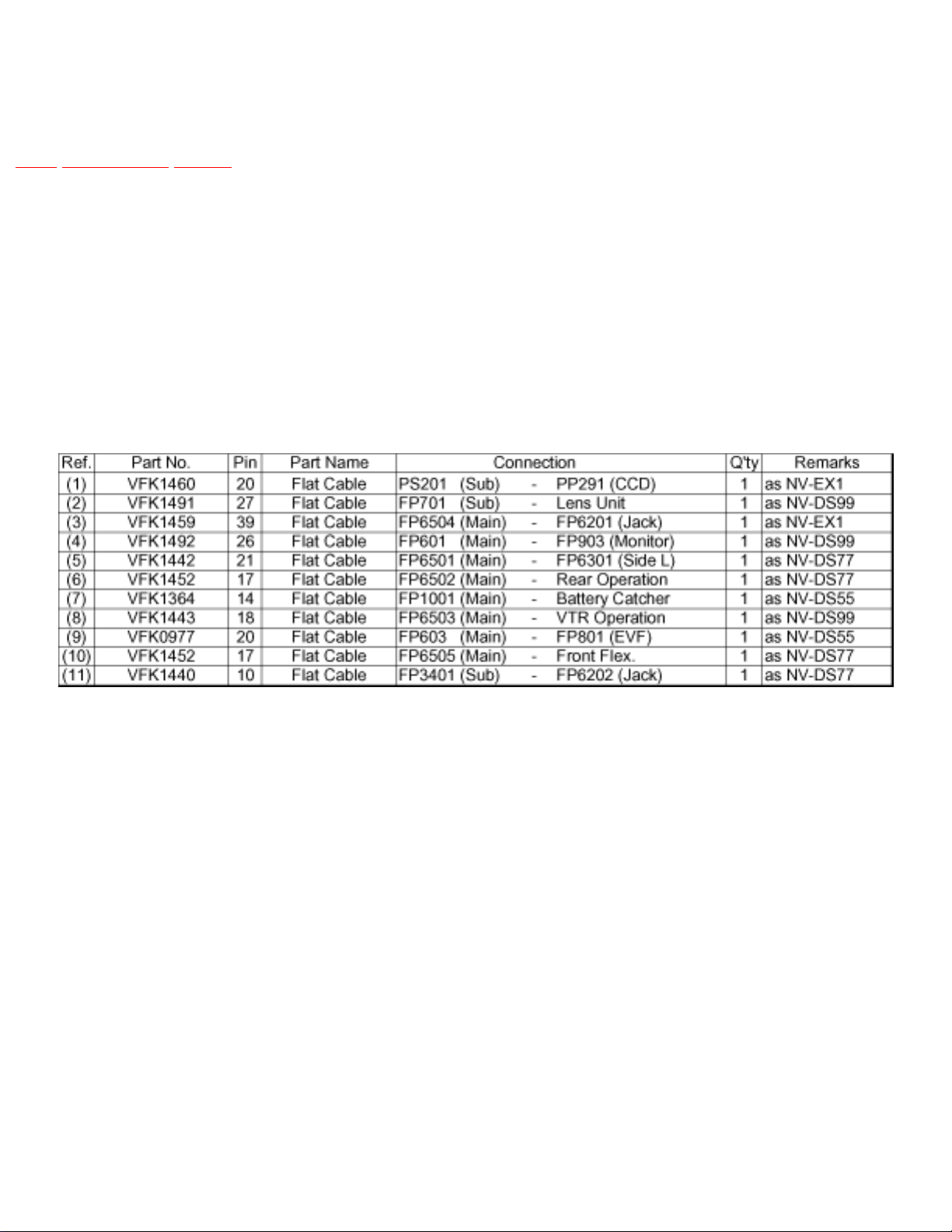
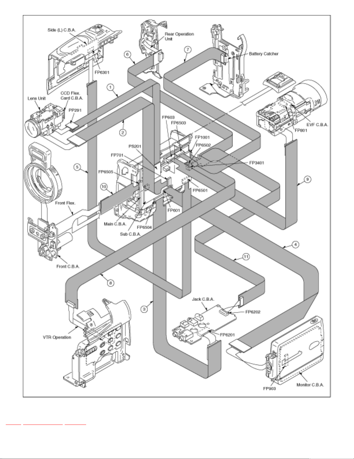
This models is required the following extension cables for all connections.
Note 1:
Use the following extension cables when checking or adjusting individual circuit boards except module
Parts.
(Main C.B.A. and Sub C.B.A.)
How to use extension cables.
Fig. T1-1
http://202.224.189.178/~sgml/viewing/NV-GX7EG/EUOT/SVC/s0303000000.html (1 of 2)17/02/2004 10:36:41
http://202.224.189.178/~sgml/viewing/NV-GX7EG/EUOT/SVC/s0303000000.html
TOP PREVIOUS NEXT
http://202.224.189.178/~sgml/viewing/NV-GX7EG/EUOT/SVC/s0303000000.html (2 of 2)17/02/2004 10:36:41

http://202.224.189.178/~sgml/viewing/NV-GX7EG/EUOT/SVC/s0304000000.html
3.4 LOCATION FOR SPARE CONNECTORS OF
THE MAIN C.B.A.& SUB C.B.A.
TOP PREVIOUS NEXT
3.4.1 MAIN C.B.A.
3.4.2 SUB C.B.A.
TOP PREVIOUS NEXT
http://202.224.189.178/~sgml/viewing/NV-GX7EG/EUOT/SVC/s0304000000.html17/02/2004 10:36:41
http://202.224.189.178/~sgml/viewing/NV-GX7EG/EUOT/SVC/s0304010000.html
3.4.1 MAIN C.B.A.
TOP PREVIOUS NEXT
TOP PREVIOUS NEXT
http://202.224.189.178/~sgml/viewing/NV-GX7EG/EUOT/SVC/s0304010000.html17/02/2004 10:36:42

http://202.224.189.178/~sgml/viewing/NV-GX7EG/EUOT/SVC/s0304020000.html
3.4.2 SUB C.B.A.
TOP PREVIOUS NEXT
TOP PREVIOUS NEXT
http://202.224.189.178/~sgml/viewing/NV-GX7EG/EUOT/SVC/s0304020000.html17/02/2004 10:36:43
http://202.224.189.178/~sgml/viewing/NV-GX7EG/EUOT/SVC/s0400000000x.html
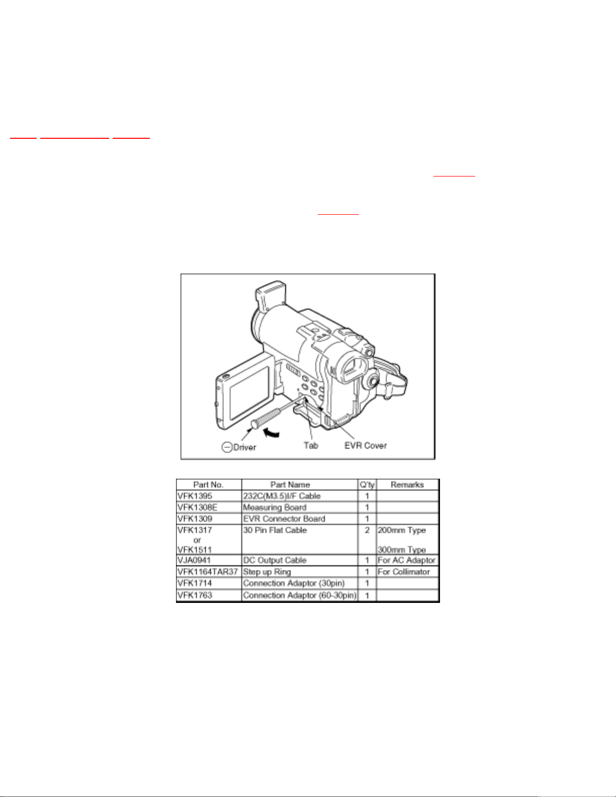
4 PREPARATION FOR ELECTRICAL
ADJUSTMENT
TOP PREVIOUS NEXT
1. Unlock the locking tab and remove the EVR connector as shown in Fig. E1 .
2. Then connect the following cables as shown in Fig. E2 .
Fig. E1
Fig. E2
http://202.224.189.178/~sgml/viewing/NV-GX7EG/EUOT/SVC/s0400000000x.html (1 of 2)17/02/2004 10:36:44
 Loading...