

PANASONIC NV-GS30EG, NV-GS30EGE, NV-GS30EGM, NV-GS30B, NV-GS30EN Service Manual
...
ORDER No. 02-SM-007
Colour Television
TX-21AP1P
Z8T Chassis
SPECIFICATIONS
Power Source: 220-240V a.c., 50Hz
Power Consumption: 52W
Stand-by Power
Consumption: 0,9W
Aerial Impedance: 75Ω unbalanced, Coaxial Type
Receiving System: PAL B/G, PAL D/K ,PAL-60
SECAM B/G, SECAM D/K
M.NTSC (AV)
NTSC (AV only)
Receiving Channels:
VHF E2-E12 VHF H1-H2 (ITALY)
VHF A-H (ITALY) VHF R1-R2
VHF R3-R5 VHF R6-R12
UHF E21-E69 CATV (S01-S05)
CATV S1-S10 (M1-M10) CATV S11-S20 (U1-U10)
CATV S21-S41 (HYPERBAND)
Intermediate Frequency:
Video/Audio
Video 38,9MHz
Audio 32,4MHz, 32,66MHz (A2 CZECH)
33,05MHz (NICAM)
33,4MHz, 33,16MHz (A2)
33,05MHz (NICAM B/G)
Colour 34,47MHz
34,5MHz, 34,65MHz
AV1 OUT Video (21 pin) 1V p-p 75Ω
Audio (21 pin) 500mV rms 1kΩ
AV FRONT Audio (RCAx2) 500mV rms 10kΩ
Video (RCAx1) 1V p-p 75Ω
High Voltage: 27kV ± 1kV
Picture Tube: A51ERF135X71 51cm
Audio Output: 2 x 5W RMS, 2 x 10W MPO
8Ω Impedance
Headphones: 8Ω Impedance
Accessories
supplied : Remote Control
2 x R6 (UM3) Batteries
Dimensions:
Height: 476mm
Width: 524mm
Depth: 473mm
Net weight: 22kg
Terminals:
AV1 IN Video (21 pin) 1V p-p 75Ω
Audio (21 pin) 500mV rms 10kΩ
RGB (21 pin) 0,7V p-p 75Ω
Specifications are subject to change without notice.
Weights and dimensions shown are approximate.
NOTE: This Service Manual should be used in conjunction with
the Z8 Technical guide.
ADJUSTMENT PROCEDURE
Item / Preparation Adjustments
+B SET-UP
1. Receive a Greyscale signal.
2. Set the controls :
Brightness Minimum
Contrast Minimum
Volume Minimum
Confirm the following voltages.
B1 3,3 ± 0,3V B13 -16 ± 1V
B2 190 ± 10V B14 27,5 ± 1,5V
B3 16 ± 1V B15 28 ± 1,5V
B4 10 ± 1V B16 13 ± 1V
B8 5 ± 0,3V B17 8 ± 1V
B11 127 ± 10V B18 5±0,3V
CUT OFF / Ug2 Test
1. Receive a Greyscale signal.
2. Degauss the tube externally.
3. Set the TV into Service Mode 1.
4. Select Cut off mode.
Set Contrast on maximum, set Brightness on center, switch
on AV mode.
Enter Service mode. Set Sub-Brightness to 31. Select Ug2
Test. Press "+" and adjust screen Vr till sharp vertical line is
visible and LED switches off. Then reduce screen Vr till LED
is just switched on (pin6 of connector E1 must be connected
to GND).
SELF CHECK
Self-check is used to automatically check the bus lines and hexadecimal code of the TV set.To enter Self-Check mode, press
the STATUS button on the remote control and at the same time press the down (-/v) button on the customer controls at
the front of the TV set. To exit Self Check, switch off the TV set at the power button.
OPTION 1 EC
OPTION 2 03
If the CCU ports have been checked and found to be incorrect or not located then " - - " will appear in place of "O.K.".
Service Aids
To aid in the service of our current chassis there are a number of Service Aids which have been made available.
• LUCI interface kit (Linked Utility Computer Interface)
Part number: TZS6EZ002
This contains interface and cables for connecting TV service connector and a PC as well as diagnostic software. As new
models are introduced upgrade software will become available.
• VICI (Visual Interactive Computer Information)
These C.D.'s contain multimedia documentation providing quick access to service information.
Part No. TZS7EZ006, TZS7EZ005, TZS8EZ001 & TZS9EZ001
1. Service Manuals
2. Instruction Books
3. Technical Information
• TASMIN (Technically Advanced System for Multimedia Interactive Notes)
As well as providing a first step towards more interactive training this product also achieves quick access to Technical
Information.
4
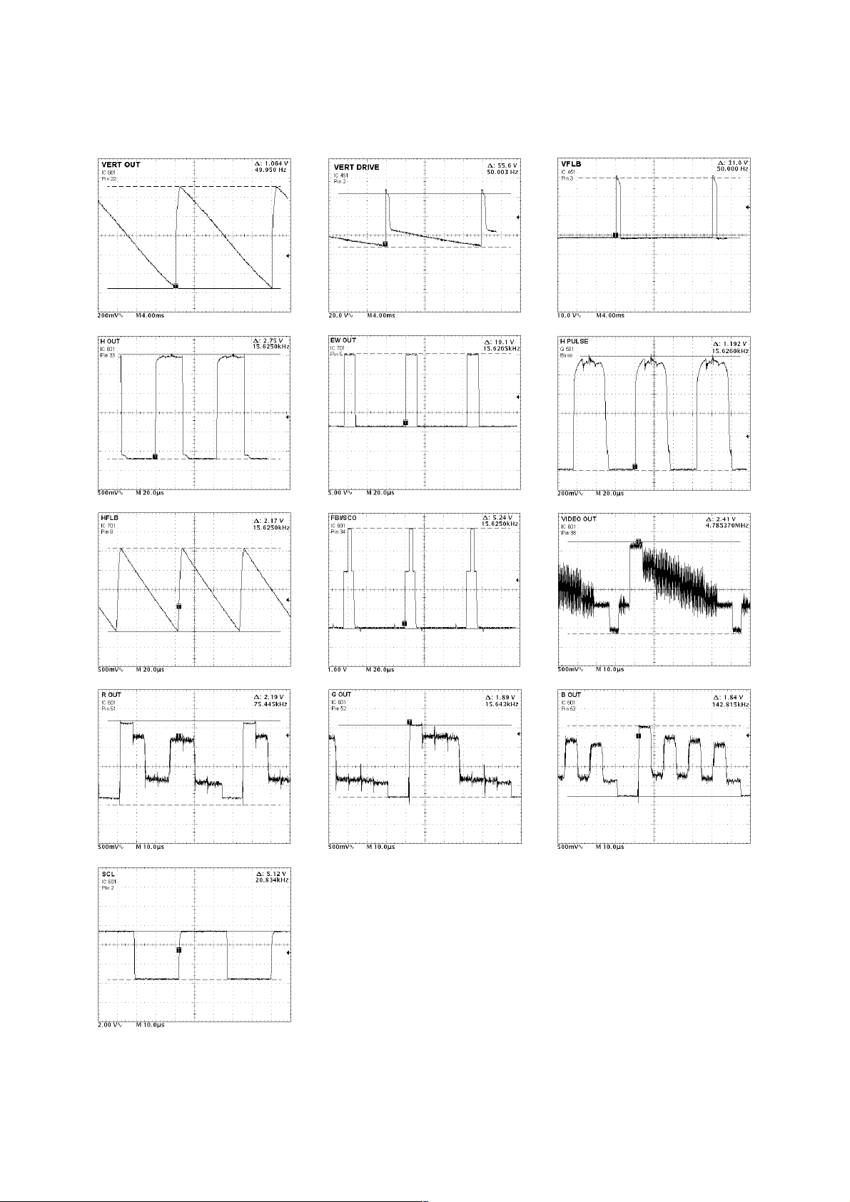
WAVEFORM PATTERN TABLE
5
CONDITIONS:
Contrast: MAX
Brightness: MID
Colour: MID
Sharpness: MID
 Loading...