

Panasonic LST 116 Installation And Operating Instructions Manual
Installation and Operating Instructions
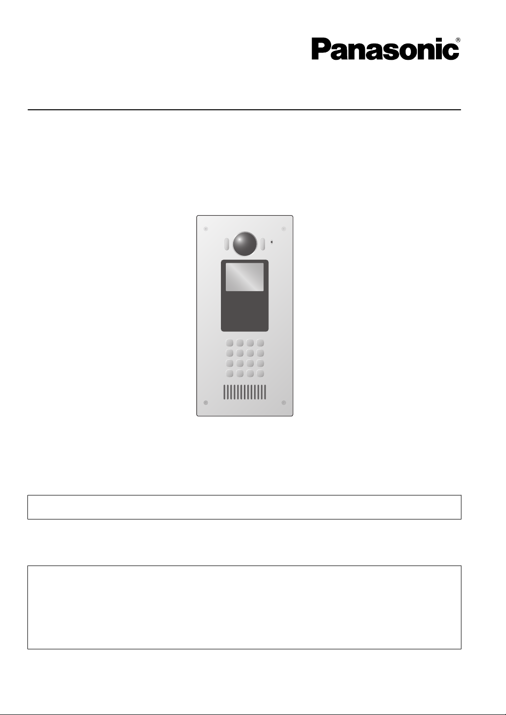
Video Intercom System — Lobby Station
Model No. VL-VN1900
Thank you for purchasing a Panasonic product.
Please follow all instructions in this document and save it for future reference.
Carefully read
This system is an auxiliary system; it is not designed to provide complete protection from property loss.
Panasonic will
Note to the installer
R This document includes instructions for both installation and operation. See the section titled
"4 Installation" for installation instructions.
R Please read this document carefully, and install the product safely and correctly by following the
instructions.
R Only use attachments/accessories specified by the manufacturer.
R The installation shall be carried out in accordance with all applicable installation rules.
the information found in the section titled "2.1 Important safety information" in particular.
not be held responsible in the event that property loss occurs while this system is in operation.

Table of Contents
1. Introduction
1.1 System overview ...........................................3
1.2 Included items ...............................................6
1.3 Optional items ...............................................6
1.4 About this document .....................................7
2. Important Information
2.1 Important safety information ..........................8
2.2 Important safety instructions .........................9
2.3 Privacy and rights of portrait .........................9
2.4 Data security .................................................9
2.5 Disclaimer .....................................................9
2.6 Other important information ........................10
2.7 General information .....................................10
2.8 For India only ..............................................11
2.9 For Europe ..................................................11
3. Preparation
3.1 Device diagrams .........................................12
4. Installation
4.1 Installation cautions .....................................13
4.2 Installing the power supply unit ...................13
4.3 Installing the lobby station ...........................15
4.4 Wiring schematic .........................................21
4.5 Wire and cable specifications ......................22
4.6 Connecting other devices ............................23
5. Programming
5.1 Programming overview ...............................24
5.2 PC programming .........................................24
5.3 Lobby station management .........................27
6. Basic operations
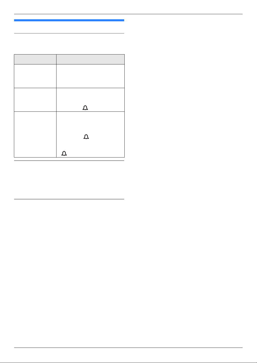
6.1 Lobby station operations .............................30
6.2 Facility staff operations using a SIP
phone ..........................................................30
6.3 Information for visitors .................................31
7. Other information
7.1 Basic troubleshooting ..................................32
7.2 Error messages ...........................................32
7.3 Specifications ..............................................33
7.4 Cleaning ......................................................34
7.5 Open source software notice ......................34
2

1.1 System overview
This document explains basic information required to
1. . Introduction
install and
with a Video Intercom System that is comprised of the
following devices.
R VL-MN1000 Room Monitor
R VL-VN1900 Lobby Station
R VL-VN1500 Door Station
R VL-VN1700 Control Box
General information about connecting other devices to
the system is also provided.
1.1.1 Main features
IP technology for smoother installation and
integration
R Voice
R Network cameras and SIP phones can be integrated
Large-capacity, expandable
R The system can support up to 2000 SIP devices
R Optional devices such as access controllers (key
R Supports multi-building installations and buildings
Easy to configure and maintain
R System settings can be configured in advance using
R Detailed settings and logs can be accessed using a
Convenient features for residents, visitors, and
facility staff
R The system can be used in "room mode" (visitors can
R Visitors can use a lobby station to call residents and
R Residents can use their room monitors to monitor
R External devices connected to residents’ room
R Facility staff can make and receive calls to and from
R Facility staff can send messages (text or voice,
configure a VL-VN1900 Lobby Station for use
and
data is carried over one cable, simplifying
installation and connections.
into the system.
when using a control box, and up to 200 SIP devices
when not.
switches, card readers, etc.), open door sensors, and
electric locks can be connected to each lobby station.
with up to 99 floors.
a computer, and uploaded on-site over the network.
web browser.
call rooms directly) or "reception mode" (visitor calls
are directed to a receptionist).
leave video messages for residents who do not
answer.
lobby stations and optional network cameras.
monitors can notify facility staff and/or residents
when triggered.
residents and visitors.
depending on system configuration) to residents’
room monitors for quick information dispersal.
1. Introduction
3
R1R2R3
1 2
R1R2R3
1 2
B
A
F
H
I
J
K
L
G D
C
M
Facility staff office
R1R2R3
1 2
R1R2R3
1 2
Facility staff office Control box
E
1. Introduction
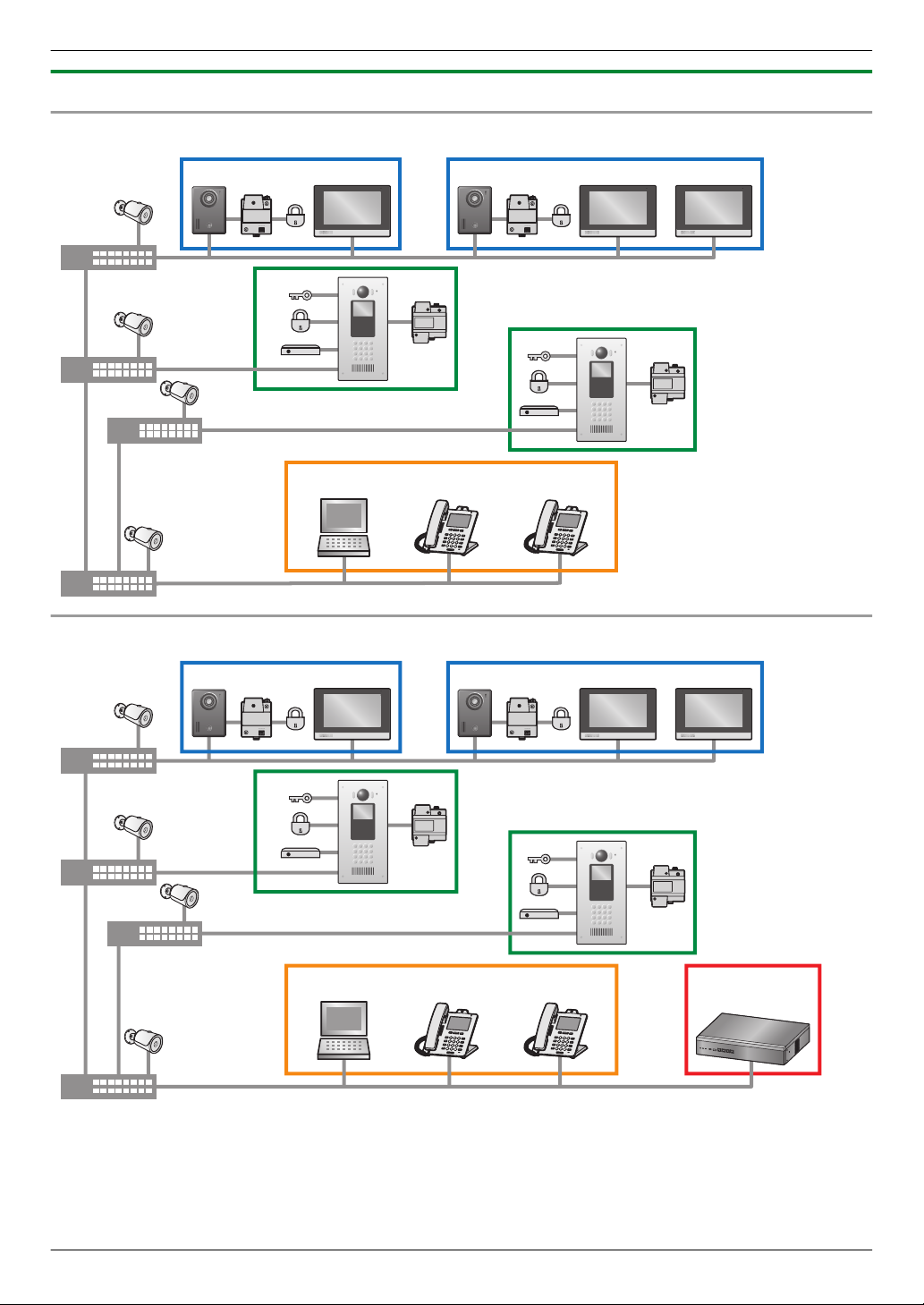
1.1.2 System configuration
Basic system example (up to 200 SIP devices*1)
Fully expanded system example (up to 2000 SIP devices**1, requires control box)
*1 "SIP devices" include lobby stations, room monitors, door stations, and SIP phones.
4
Maximum number of devices
R1R2R3
1 2
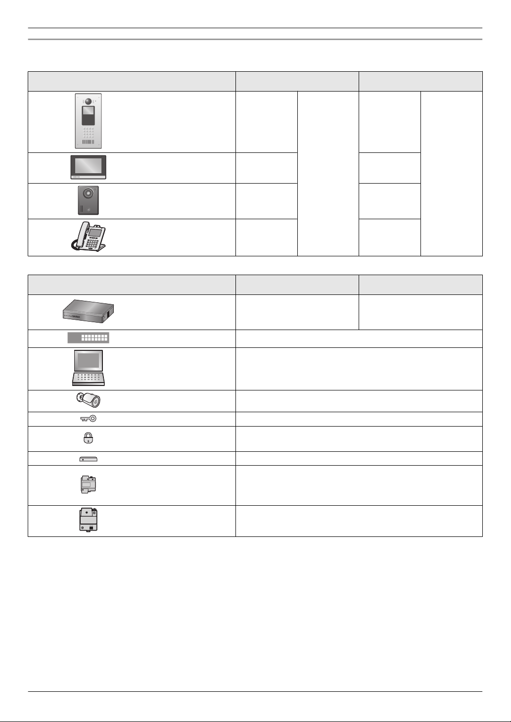
SIP devices
Item Without control box With control box
1. Introduction
A Lobby station
B
C
Room monitor
Door station
D SIP phone
*1
50
*2
*2
5 per room
1 per room 1 per room
50
*3
*4
200
*1
50
5 per room
*4
50
Other devices
Item Without control box With control box
E Control box — 1
F
G
Switching hub
Computer (for
programming)
H Network camera
*5
—
—
*6
500
*3
2000
I Access controller 1 per lobby station
J Electric lock
1 per lobby station
1 per door station
K Open door sensor 1 per lobby station
1 per lobby station
L Power supply unit
M
Relay box
1 per room monitor
1 per door station
1 per door station
*2
*2
*7
*1 Up to a combined total of 8 lobby station and door station cameras can be registered to a room monitor for easy
camera monitoring.
If room monitors and door stations are not powered by Power over Ethernet (PoE), a power supply unit is required.
*2
*3 Up to 256 rooms can have multiple room monitors. All other rooms can have only one room monitor. For more
information, refer to the documentation of the control box (PC Programming Manual).
*4 Up to 18 SIP phones can be registered to a room monitor for easy calling.
*5 If PoE-compatible switching hubs are used, they can supply power to room monitors and door stations.
*6 Up to 32 network cameras can be registered to a room monitor for easy camera monitoring.
*7 A relay box is used to connect an electric lock to a door station.
5
1. Introduction
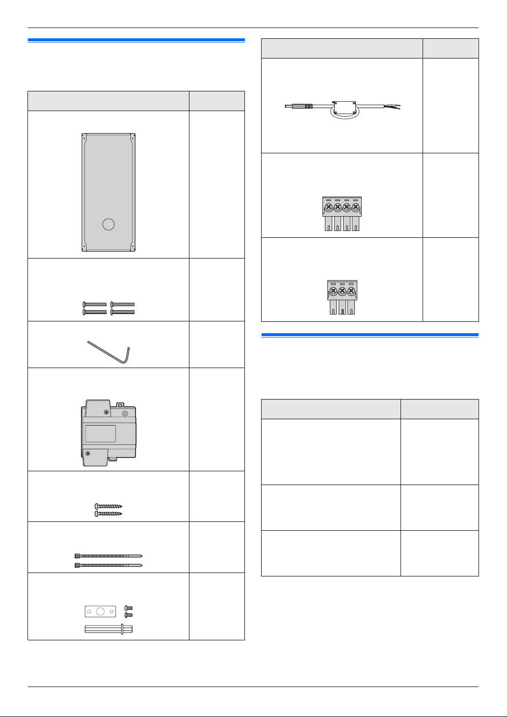
1.2 Included items
The following items are included in addition to the lobby
station.
Item Quantity
Flush mount box 1
Hex screw (4 mm ´ 25 mm)
Used to
flush mount box.
Hex wrench 1
secure the lobby station to the
4
Item Quantity
DC plug with ferrite core
Used to connect the power supply unit
to the lobby station.
Note:
R Do not remove the ferrite core.
4-pin terminal block
Used to connect wires to the K-IN
connection terminals.
3-pin terminal block
Used to connect wires to the K-OUT
connection terminal.
1
1
1
Power supply unit
VL-PS240
Screw (4 mm ´ 40 mm)
Used to mount the power supply unit.
Cable binder
Used to secure the AC and DC wires.
Vandal proof post kit
Includes
post, bracket, and 2 screws.
a
1.3 Optional items
1
2
2
1
The following items are sold separately. Please contact
your nearest Panasonic dealer for sales information.
Compatible system devices (as of March, 2017)
Item Model no.
Door Station
IP-compatible door station with
built-in push
card reader. Typically installed
immediately outside the
residence.
Room Monitor
IP-compatible room monitor with
touch screen. Typically installed
inside a residence.
Control Box
Allows the system to
accommodate up to 2000 SIP
devices.
button, camera, and
VL-VN1500
VL-MN1000
VL-VN1700
6
1.4 About this document
Symbols, expressions, and styles
The following
in this document.
Item How it is expressed
symbols, expressions, and styles are used
1. Introduction
Text displayed on
the product’s
display
Buttons with
printing on them
Procedures Usually written in an
Terms and illustrations
R Model number suffixes (e.g., the "BX" in
"VL-VN1900BX") are omitted unless necessary.
R Design and specifications are subject to change
without notice.
R Illustrations
Trademarks
R The software of this product is based in part on the
work of the Independent JPEG Group.
R Microsoft and Windows are either registered
trademarks
the United States and/or other countries.
R MIFARE is a registered trademark of NXP B.V. and
is used under license.
R All other trademarks identified herein are the property
of their respective owners.
Text is displayed in a special
font, usually enclosed in
quotation marks.
Example: “IP Config”
Button printing is displayed,
usually wrapped in thick
brackets.
Example: M
abbreviated
be omitted.
Example: Enter the room
number ® M N.
(Meaning: Enter the room
number and then press the
N button.)
M
may vary slightly from the actual product.
or
trademarks of Microsoft Corporation in
N
style. The verb may
7
WARNING
CAUTION
2. Important Information
2.1 Important safety information
To prevent
2. . Important Information
ensure proper and safe operation of your product, read
this section carefully before using the product.
Preventing fire, electric shock, and short circuits
R Leave installation
work requires technical knowledge and
experience. Electrical connection work should be
performed by certified personnel only. Failure to
observe this may cause fire, electric shock,
injury, or damage to the product. Consult the
dealer.
R Use only the power supply unit VL-PS240.
R Do not place objects on the power cables. Install the
product where no one can step or trip on the power
cables.
R Do not allow the power cables to be excessively
pulled, bent or placed under heavy objects.
R Make sure all connections from the power outlet to
the power supply unit are secure.
R Never touch the power supply unit and power cables
with wet hands.
R Do not use the power supply unit for outdoor
installations (it is for indoor use only).
R Do not disassemble or modify the product. Refer
servicing to an authorised service centre when
service is required. Disassembling the product or
manipulating the product in a way not described in
the documentation may expose you to dangerous
voltages and other risks.
R Do not touch the product or the power supply unit
during an electrical storm. There may be a remote
risk of electric shock from lightning.
R Never install wiring during a lightning storm.
R Do not connect non-specified devices.
R Do not connect a power cable to a terminal that is not
specified in this document.
R When opening holes in walls for installation or wiring,
or when securing the power cable, make sure you do
not damage existing wiring and ductwork.
R Do not make any wiring connections when the power
outlet is turned on.
R Do not install the product and power supply unit in the
following places:
– Places where the product and power supply unit
– Places where there is a high concentration of dust
R Do not push any objects through the openings of the
product.
R If any of the following conditions occur, disconnect
the Ethernet (LAN) cable from the product,
disconnect the power supply unit from the power
severe injury or loss of life or property, and to
work to the dealer. Installation
may be splashed with water or chemicals
or high humidity
outlet, and then refer servicing to an authorised
service centre.
The product emits smoke, an abnormal smell or
–
makes unusual noise
–
The power cables are damaged or frayed
– Metal objects have been dropped inside the
product
R When existing wires are used, it is possible that they
contain AC voltage. Contact an authorised service
centre.
Preventing accidents, injuries, and property damage
R Do not use the product in unstable areas or areas
prone to strong vibrations. This may cause the
product to fall, resulting in damage to the product or
injury.
R Always connect power cables to the appropriate
connection terminals. Incorrectly connecting the
power cables may damage the power supply unit.
R To prevent
to prevent electric shock, secure the power cables
using the included cable binders and attach the cable
covers.
R Insert the power cables firmly all the way into the
terminals. If the cables are not inserted all the way,
heat may be generated.
R If the wiring passes outdoors, use a conduit and a
surge protector.
R If the wiring passes underground, use a conduit, and
do not make any connections underground.
R Install the product securely adhering to the
instructions in this document to prevent it from falling
off the wall. Avoid installing onto low-strength walls,
such as gypsum board, ALC (autoclaved lightweight
concrete), concrete block, or veneer (less than
18 mm thick) walls.
R The power supply unit is used as the main disconnect
device. Ensure that the power outlet is installed near
the product and is easily accessible.
R Do not put your ear(s) near the speaker, as loud
sounds emitted from the speaker may cause hearing
impairment.
the power cables from disconnecting and
8

2.2 Important safety instructions
When using
always be followed to reduce the risk of fire, electric
shock, or personal injury.
Use only the power supply unit indicated in this
document.
SAVE THESE INSTRUCTIONS
this product, basic safety precautions should
2.3 Privacy and rights of portrait
When installing or using the product, please take into
consideration the rights of others with regard to privacy.
R It is generally said that "privacy" means the ability of
an individual or group to stop information about
themselves from becoming known to people other
than
those whom they choose to give the information.
"Rights of portrait" means the right to be safe from
having your own image taken and used
indiscriminately without consent.
2.4 Data security
In order
security guidelines (listed below) must be observed.
Failure to do so may result in the following.
R Loss, leakage, falsification or theft of user
R Unauthorised or illegal use of the system by a third
R Interference or suspension of service caused by a
What is user information?
User information is defined as the following types of
information.
R Information stored in the product
R Information stored on the computer that is used by
Data security guidelines
R Observe proper management of passwords.
R Use caution when entering or saving contact
to use the system safely and correctly, the data
information.
party.
third party.
– System event information
– Resident names and room numbers
– System and device settings
the setup tool
– Resident names and room numbers
– System and device settings
– Passwords can be used to program the system,
open doors, etc. Select passwords that are
difficult to guess, change them regularly, and
keep them secret. Assign a unique password to
each device.
information for use by the system.
– When configuring email addresses, room
numbers, or other contact information, make sure
all information is entered correctly. Incorrect
2. Important Information
information could cause user information to be
disclosed to unintended recipients.
R Protect user information when sending the
product to be repaired, or when handing it over
to a third party.
Use the product's reset function to initialise the
–
product before when sending the product to be
repaired or handing it over to a third party.
–
Note that user information may be deleted or
initialized when the product is repaired.
– Refer all repairs to a trusted Panasonic service
centre.
R Protect user information stored on the computer
used to configure the system.
– When user information is stored on a computer,
the confidentiality of that information becomes the
responsibility of the installer. Take precautions to
prevent the unauthorised use of the computer
and the setup tool used for performing system
configuration or maintenance.
– Connect the computer to the network only when
performing system configuration or maintenance,
and disconnect the computer from the network as
soon as the work is complete.
– Before disposing of the computer, ensure that
data cannot be retrieved from it by formatting the
hard disk and/or rendering it physically unusable.
R Protect user information when disposing of the
product.
– Use the product's reset function to initialise the
product before disposing of the product.
2.5 Disclaimer
R Recorded data
of incorrect operations, exposure to static electricity,
accidents, malfunction, repairs or other operations.
Panasonic assumes no liability for any direct or
indirect damages resulting from the loss or alteration
of recorded data.
R To the maximum extent permitted by law, Panasonic
assumes no responsibility for injuries or property
damage resulting from failures arising out of improper
installation or operation inconsistent with this
document.
may be altered or deleted as a result
9
2. Important Information
2.6 Other important information
R When you
of time, unplug it from the power outlet.
R If you stop using this product, remove it from the walls
to prevent it from falling off.
R When power fails, this product cannot be used.
R Panasonic may not be liable for damages due to
external factors such as power failures.
leave the product unused for a long period
2.7 General information
R In the event of problems, you should contact your
equipment supplier in the first instance.
R After removing the product and any included items
from the packaging, store, dispose, or recycle the
packaging as necessary. Note that certain types of
packaging may be a suffocation or choking hazard.
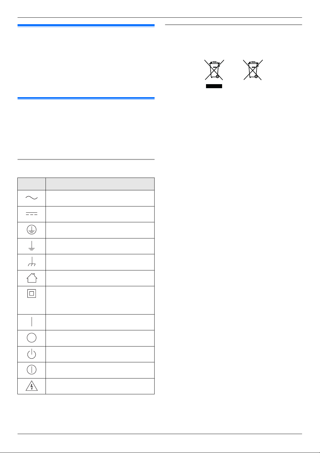
Graphical symbols for use on equipment and their
descriptions
Symbol Explanation
Alternating current (A.C.)
Direct current (D.C.)
Protective earth
Protective bonding earth
Functional earth
For indoor use only
Class P equipment (equipment in which
protection against
Double Insulation or Reinforced
Insulation)
electric shock relies on
Disposal of Old Equipment and Batteries (Only for
European Union and countries with recycling
systems)
A B
These symbols (A, B) on
or accompanying documents mean that used electrical
and electronic products and batteries must not be mixed
with general household waste. For proper treatment,
recovery and recycling of old products and batteries,
please take them to applicable collection points in
accordance with your national legislation.
By disposing of them correctly, you will help to save
valuable resources and prevent any potential negative
effects on human health and the environment.
For more information about collection and recycling,
please contact your local municipality. Penalties may be
applicable for incorrect disposal of this waste, in
accordance with national legislation.
For business users in the European Union
If you wish to discard electrical and electronic equipment,
please contact your dealer or supplier for further
information.
Information on Disposal in other Countries outside
the European Union
These symbols (A, B) are only valid in the European
Union. If you wish to discard these items, please contact
your local authorities or dealer and ask for the correct
method of disposal.
Note for the battery symbol
This symbol (B) might be used in combination with a
chemical symbol. In this case it complies with the
requirement set by the Directive for the chemical
involved.
the products, packaging, and/
10
"ON" (power)
"OFF" (power)
Stand-by (power)
"ON"/"OFF" (power; push-push)
Caution, risk of electric shock
2. Important Information
2.8 For India only
Declaration of Conformity with the requirements of
the E-Waste (Management) Rules
The Product
reduction of hazardous substances of the E-Waste
Rules.
The content of hazardous substance with the exemption
of the applications listed in SCHEDULE II of the E-Waste
Rules:
1. Lead (Pb) – not over 0.1% by weight;
2. Cadmium (Cd) – not over 0.01% by weight;
3. Mercury (Hg) – not over 0.1% by weight;
4. Hexavalent chromium (Cr6+) – not over 0.1% by
weight;
5. Polybrominated biphenyls (PBBs) – not over 0.1% by
weight;
6. Polybrominated diphenyl ethers (PBDEs) – not over
0.1% by weight.
Disposal information
is in conformity with the requirements of the
2.9 For Europe
Declaration of Conformity
Panasonic Corporation declares that the radio
equipment type (VL-VN1900BX/VL-VN1900EX) is in
compliance with Directive 2014/53/EU.
The full text of the EU declaration of conformity is
available at the following internet address:
http://www.ptc.panasonic.eu/doc
Contact to Authorised Representative:
Panasonic Testing Centre
Panasonic Marketing Europe GmbH
Winsbergring 15, 22525 Hamburg, Germany
Ecodesign information
Ecodesign information under EU Regulation (EC) No.
1275/2008 amended by
No. 801/2013. From 1 January 2015.
Please visit here: http://www.ptc.panasonic.eu/erp
Click [Downloads] ® [Energy related products
information (Public)]
Power consumption in networked standby and guidance
are mentioned in the web site above.
This device is classified as a HiNA device (networked
equipment with high network availability), according to
Ecodesign requirements.
(EU) Regulation
For the purpose of recycling to facilitate effective
utilization of resources, please return this product to a
nearby authorized collection centre, registered
dismantler or
disposing of this product.
Please see the Panasonic website for further information
on collection centres, etc., or call the toll-free number
below.
Website:
http://www.panasonic.com/in/corporate/sustainability/
panasonic-india-i-recycle-program.html
Service helpline: 1800 103 1333 or 1800 108 1333
recycler, or Panasonic service centre when
11
 Loading...