

Panasonic LS-H, LS-H91, LS-H92, LS-H21, LS-H22 Instruction Manual
INSTRUCTION MANUAL
Laser Sensor Head
LS-H Series
Thank you very much for purchasing Panasonic products. Read this Instruction
Manual carefully and thoroughly for the correct and optimum use of this product.
Kindly keep this manual in a convenient place for quick reference.
Never use this product as a sensing device for personnel protection.
●
In case of using sensing devices for personnel protection, use
●
products which meet standards, such as OSHA, ANSI or IEC etc.,
for personnel protection applicable in each region or country.
Do not view direct beam by the unprotected eye or with an
●
WARNING
optical instrument. Lasers are potentially hazardous.
Use of control or adjustment or performance of procedures
●
other than those specified in this instruction manual may
result in hazardous radiation expose.
1
FOR SAFE USE OF A LASER PRODUCT
In order to prevent the accident by laser product and protect the users,
●
JIS C 6802
-2014 “Safety of laser products” was established based on the
regulation of IEC (International electrotechnical Commission). This
regulation classifies laser products according to the level of hazard, and
provides the safety measures for respective classes.
This product are classified as “Class 2 laser products” according to
IEC 60825-1-2014 (JIS C 6802-2014) “Safety of laser products”.
Laser hazardous class
●
Classification according to IEC 60825-1
Visible beam, low power. Blink response of eye affords protection.Class 2
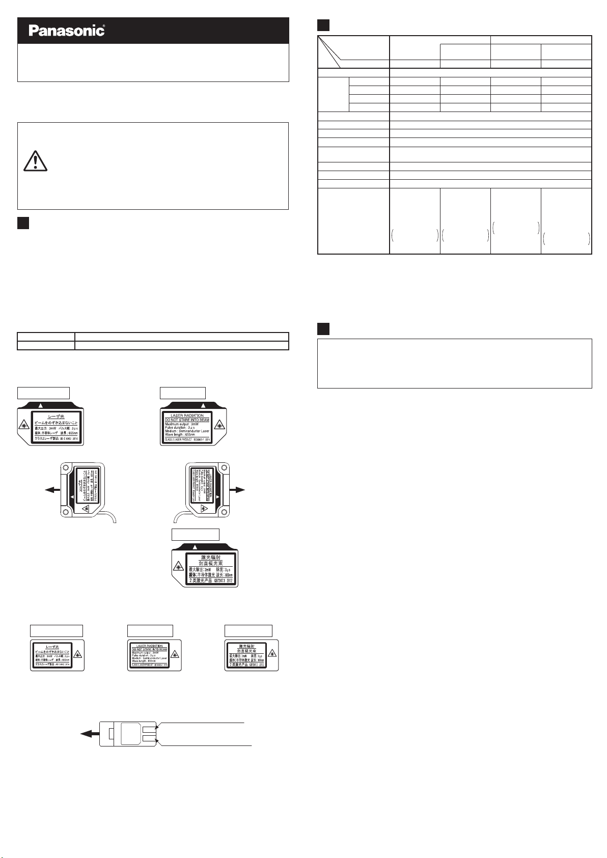
The following label is affixed on this product in accordance with the
●
Description of hazardous evaluationClass
-2014 (JIS C 6802-2014)
Safety of laser product.
Warning label
・
In Japanese
クラス1レーザ製品
JIS C 6802
(Based on JIS C 6802-2014)
In English
<Label position>
Direction of
laser emission
JIS C 6802
クラス1レーザ製品
When this product is used in China,
●
In Chinese
affix the chinese warning label
(accessory) on the label in the
product.
If the affixed label on this product may not be visible after installation of
●
the product, affix the accessory lable close to the product where you can
see.
In Japanese
In English In Chinese
MJE-LSH No.0059-56V
(Based on IEC 60825-1-2014)
Direction of
laser emission
(Based on GB 7247.1
-2012
)
2
SPECIFICATIONS
Coaxial retroreflective type (Note 2)
Type
Model No. (Note 1)
Item LS-H21LS-H91
Sensing
range
(Note 4)
Ambient temperature
Ambient humidity
Emitting element
Accessories
Notes: 1)
The model No. with suffix '-C5' stands for the 5m cable length type.
(e.g.) LS-H91-C5
2)
The model No. of retroreflective type sensor with the suffix '-Y' is the sensor without the RF-330
and RF-230 reflector. Arrange the reflector separately.
(e.g.) LS-H91-Y
3)
LS-H22 is the model No. for the long sensing range spot reflective type (LS-H21) with the
lens attachment for line reflective type (LS-MR1). 'LS-H21' is indicated on the actual product.
4)
Configure the mode settings in the applicable amplifier LS-400 series.
3
CAUTIONS
0.1 to 3m 30 to 300mm 30 to 300mmH-SP mode
0.1 to 3m 30 to 300mm 30 to 300mmFAST mode
0.1 to 5m 30 to 500mm 30 to 500mmSTD mode
0.1 to 7m 30 to 1,000mm 30 to 1,000mmU-LG mode
-10 to +55℃ (No dew condensation or icing allowed), Storage: -20 to +70℃
Red semiconductor laser Class 2 (IEC/JIS/GB/KS standard)
(Max. output: 3mW or less, Peak emission wavelength: 655nm)
Connector for
amplifier: 1 pc.
RF-330 (Reflector)
: 1 pc.
Warning label
Japanese / English
/ Chinese
: 1 set
Long sensing
range
LS-H92
LS-400 seriesApplicable amplifier
0.2 to 10m
0.2 to 10m
0.2 to 20m
Orange LED (Lights up when amplifier output is ON)Operation indicator
Enclosure: PBT (Attachment: PEI), Lens cover: AcrylicMaterial
0.2 to 30m
Green LED (Lights up when laser is emitted)Laser emission indicator
35~85% RH, Storage: 35~85% RH
2
shielded cable, 2m longCable
0.1mm
30g approx.Weight
Connector for
amplifier: 1 pc.
RF-230 (Reflector)
: 1 pc.
Warning label
Japanese / English
/ Chinese
: 1 set
Diffuse reflective type
Long sensing range
spot reflective
Connector for
amplifier: 1 pc.
Warning label
Japanese / English
/ Chinese
: 1 set
Long sensing range
line reflective
LS-H22 (Note 3)
Connector for
amplifier: 1 pc.
LS-MR1 (Lens
attachment for line
reflective type): 1 pc.
Warning label
Japanese / English
/ Chinese
: 1 set
This product has been designed to meet the specifications when it is used
along with the optional exclusive amplifier. If an amplifier other than the
exclusive amplifier is used, not only the specifications may not be met, but
it may also be a cause for malfunction or break down. Hence, please
ensure to use this product along with the optional exclusive amplifier.
This product has been developed / produced for industrial use only.
●
Always use the sensor with the connector to be joined to the amplifier.
●
Make sure that the power is off while wiring to the amplifier.
●
In case noise generating equipment (switching regulator, inverter motor
●
etc.) is used in the vicinity of this product, connect the frame ground
(F.G.) terminal of the equipment to an actual ground.
If power is supplied from a commercial switching regulator, ensure that
●
the frame ground (F.G.) terminal of the power supply is connected to an
actual ground.
Do not use the sensor during the initial transient time (0.5 sec.) just after
●
the power supply is switched on.
Do not run the wires together with high-voltage lines or power lines or put
●
them in the same raceway. This can cause malfunction due to induction.
Take care that the sensor head is not directly exposed to fluorescent
●
lamp from a rapid-starter lamp or a high frequency lighting device, as it
may affect the sensing performance.
The sensor head cable cannot be extended.
●
Make sure that stress is not applied to the sensor head cable joint.
●
This sensor is suitable for indoor use only.
●
Do not allow any water, oil fingerprints, etc., which may refract light, or
●
dust, dirt, etc., which may block light, to stick to the emitting/receiving
surfaces of the sensor head. In case they are present, wipe them with a
clean, soft cloth or lens paper.
Do not use the sensor in vaporous, dusty or corrosive gas atmospheres.
●
Take care that the sensor does not come in contact with water, oil,
●
grease or organic solvents, such as, thinner, etc.
Make sure that the power is off while cleaning the emitting/receiving
●
windows of the sensor head.
Laser emission indicator (green)
・
While laser is emitted, the laser emission indicator (green) of the sensor
head lights up.
This indicator is visible even when wearing laser protective glasses.
Direction of
laser emission
Operation indicator (Orange)
Laser emission indicator (Green)
4
MOUNTING
●●The tightening torque should be 0.5N・
m or less.
M3 (length 12 mm)
screw with washers
When placing the sensor horizontally or
vertically, the reflector must also be
positioned horizontally or vertically as
Sensor bracket
(optional)
shown in Fig. 1 below.
If the sensor is placed horizontally or vertically but the mirror is tilted as
shown in Fig. 2 below, the reflection amount will decrease, which may
cause unstable detection.
<Fig. 1 Proper positioning>
When placing the sensor horizontally or vertically, the reflector shall also be
positioned horizontally or vertically.
Good
<Fig. 2 Improper positioning>
When placing the reflector tilted even when the sensor is positioned
horizontally or vertically.
Not good
Note: The diagrams above are examples for the sensor head (LS-H91) with the reflector (RF-330).
For the sensor head (LS-H92) with the reflector (RF-230), take care of the posisioning as well.
5
COAXIAL RETROREFLECTIVE TYPE
(Only for LS-H91 and LS-H92)
In principle, the coaxial retroreflective type (LS-H91 and LS-H92) may be
●
unable to detect a mirror object or an object which easily diffuses the receiving
light at a short sensing distance since the polarized light becomes unstable.
In this case, take the following measures.
<Measures>
Lower the receiving light sensitivity with the M.G.S. function of the
・
amplifier.
Change the response time.
・
Make the distance between the sensor head and the sensing object
・
farther.
The receiving light intensity may change depending on the surface
●
condition of the reflector. When a threshold value is set with the applicable
amplifier LS-400 series, sufficient margin should be taken into accout.
LS-H92 is in super high sensitivity setting. Thus, the output may be unstable
●
since it can be easily affected by extraneous noise. In this case, lower the
the receiving light sensitivity with the M.G.S. function. The sensing distance
depends on the receiving light sensitivity as shown in the table below.
M.G.S. function
Response time
H-SP, FAST
STD
U-LG 30m 20m 10m 7m
Note: The value above is with the reflector (RF-230).
6
SPOT-SIZE ADJUSTER
(Only for LS-H21 and LS-H22)
The diffuse reflective type (LS-H21 and LS-H22) incorporates the
●
spot-size adjuster to adjust the size of spot diameter.
7
LENS ATTACHMENT FOR LINE REFLECTIVE
TYPE (LS-MR1) (Only for LS-H21 and LS-H22)
The lens attachment for line reflective type (LS-MR1) mounted in the
●
long sensing range line reflective type (LS-H22) is removable.
When LS-H22 is used without LS-MR1, it will provide the equivalent
performance to the long sensing range spot reflective type (LS-H21). In
addition, the optional LS-MR1 can be attached to LS-H21 to obtain the
performance equivalent to LS-H22.
Keep the lens from dust, dirt, water, oil, grease, etc.
●
Do not apply any excessive bending force
●
to LS-MR1. Such force may cause damage.
Removing method
Insert a screwdriver into the fixing
①
slot located at the top of sensor.
Tilt the screwdriver inserted in Step
②
① to remove LS-MR1.
Level 4 Level 3 Level 2 Level 1
-
-
Turn the spot-size adjuster clockwise or counterclockwise to adjust the
spot diameter at your desired detecting distance.
However, if the adjuster is over turned, it may be damaged.
10m 4m 3m
20m 8m 5m
DescriptionSpot-size adjuster
Fixing slot
Lens
attachment for
line reflective
type (LS-MR1)
Fixing slot
Fixing hooks
Mounting method
The size of upper fixing hook of LS-MR1 is not same as lower fixing
①
hook.
After confirming upper and lower fixing hooks, insert LS-MR1 upper fixing
hook into the fixing slot at the top of sensor and then insert LS-MR1
lower fixing hook into the fixing slot at the bottom of sensor.
After mounting, check that LS-MR1 is properly fixed to the sensor.
②
8
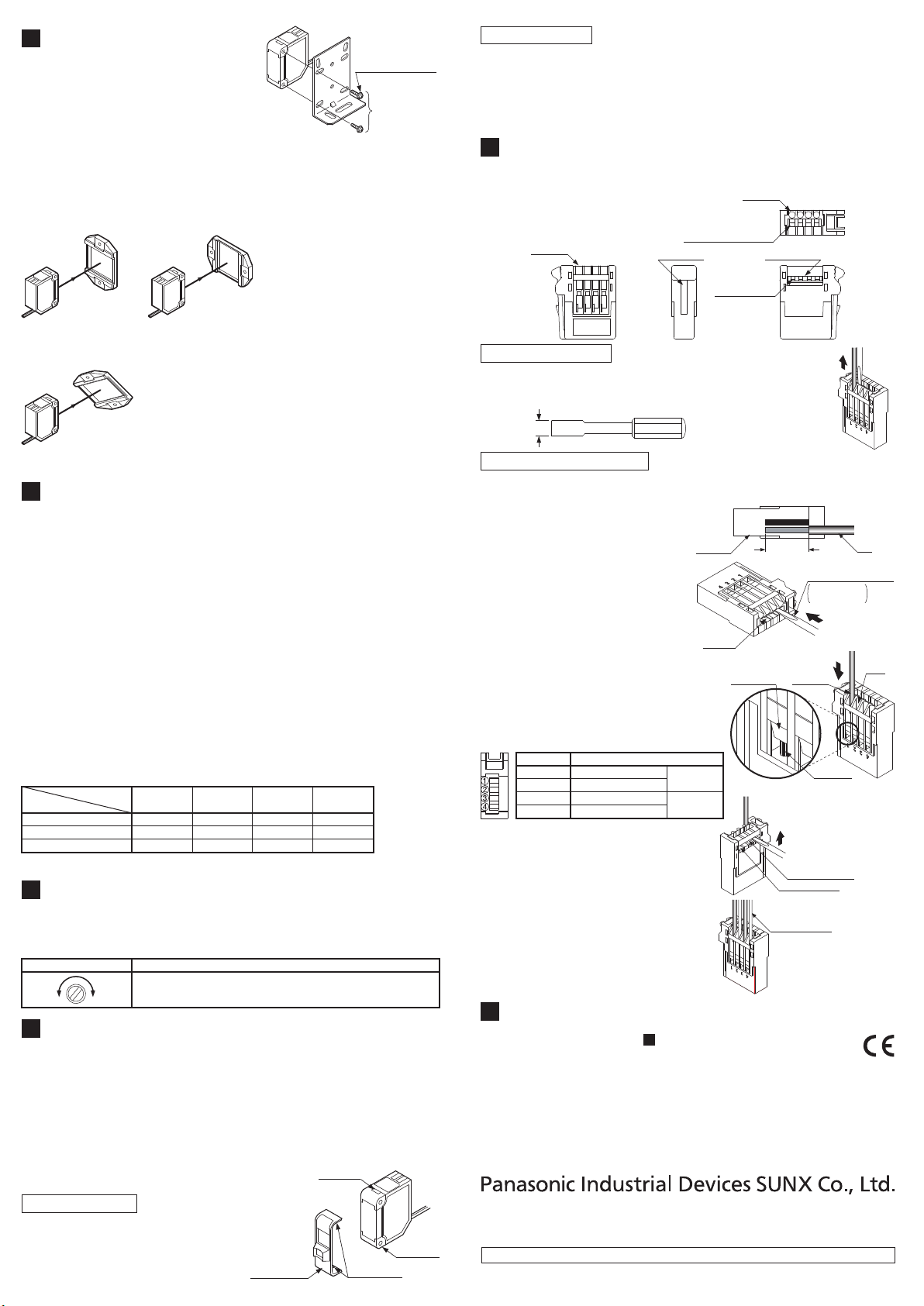
WIRE CONNECTION
The cable of sensor head can be shortened to your desired length.
●
However, it cannot be extended.
<Connector for amplifier connection>
Wire inlet
1234
Operating lever (white)
Strip gauge
STRIP GAUGE
Wire inlet
Operating lever
(white)
Releasing slot
Releasing procedure
Use a flat-head screwdriver (Blade width: 2mm or less) to
①
push the operating lever (white) located at the wire inlet
and remove the wire.
Blade width
2mm or less
Wire connecting procedure
Process the core length to 7 to 8 mm in accordance with 'STRIP
①
GAUGE' indicated on the side of this unit, and twist the core several
times.
When using shielded wires,
twist the wire until obtaining the
diameter of φ1.2 mm or less.
Use a flathead screwdriver (Blade
②
width: 2 mm or less) to push the
operating lever (white) located at
Connector
for amplifier
STRIP GAUGE
Core length:
7 to 8 mm
Wire
Flathead screwdriver
Blade width:
2mm or less
the operating area until it is
locked.
Insert the wire to the innermost of
③
the wire inlet.
Check that the shielded wire is
Operating
area
Wire
connection
area
Shielded
wire
Wire
inlet
properly inserted into the wire inlet
as well as that the core end has
passed through the wire connection
area as shown in the right figure.
Terminal No.
①
②
③
④
Place the head of a flathead
④
Connecting cable
Conductive core: Brown
Shielded wire
Conductive core: Yellow
Shielded wire
Cable color:
Gray
Cable color:
Black
Core end
screw-driver underneath the
operating lever (white) through the
releasing slot, and lift the screwdriver head.
Operating lever
(white)
Releasing slot
If you hear a snap, the operating
lever (white) is returned and the
wire is fixed.
⑤
Lightly pull the wire to ensure that
Shielded wires
wire is not loose. When using
shielded wires, also check that
they do not contact each other.
9
INTENDED PRODUCTS FOR CE MARKING
The models listed under “ SPECIFICATIONS” come with CE
●
2
Marking.
As for all other models, please contact our office.
http://panasonic.net/id/pidsx/global
Overseas Sales Division (Head Office)
2431-1 Ushiyama-cho, Kasugai-shi, Aichi, 486-0901, Japan
Phone: +81-568-33-7861 FAX: +81-568-33-8591
For sales network, please visit our website.
PRINTED IN JAPAN © Panasonic Industrial Devices SUNX Co., Ltd. 2017
 Loading...