

Panasonic LNS-W01, lns-W01Z, lns-T01, lns-T01Z, lns-T02 Operation Manual
...
LCD PROJECTOR
LENS REPLACEMENT
AND
INSTALLATION PROCEDURES
English
Français
Español
Deutsch
Italiano
1AA6P1P2923-- (MV6A)
- 1 -
E
LCD PROJECTOR
LENS REPLACEMENT AND INSTALLATION PROCEDURES
CAUTION
When installing or replacing the Projection Lens, refer to this manual. For
installation of the lens, use the parts designated in the manual. Do not use the
installation manual and Light-Block Sheets in the lens package.
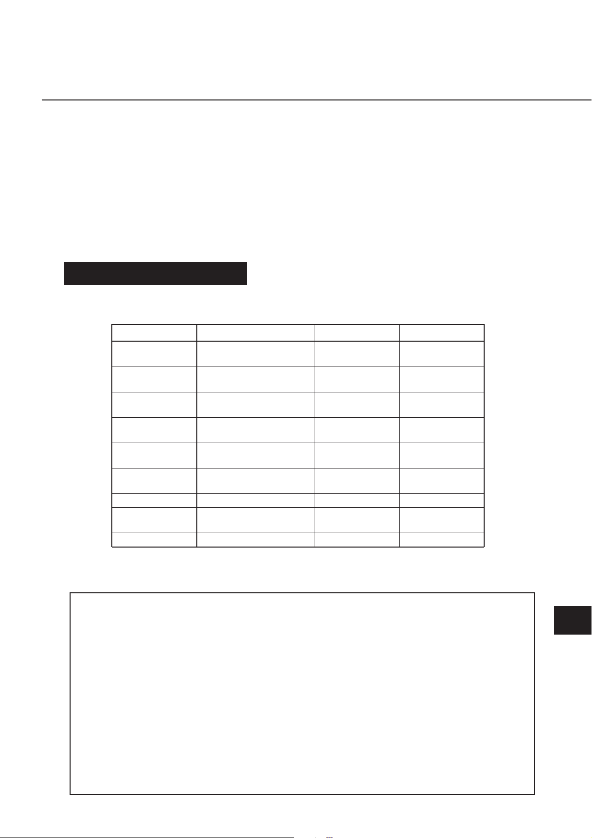
Check the following parts supplied to this projector.
NOTES ON LENS INSTALLATION
●
Lens installation and replacement should be made by the qualified service
personnel.
●
Be sure to install the lens following this procedure precisely.
●
Do not touch or remove any parts except the lens and related parts. It may
result in malfunctions, electrical shock, fire hazard or other accidents.
●
Before installing or replacing the lens, check the Model No. of the
Projection Lens matches to the projector.
●
When moving or setting up the projector, be sure to replace the Lens Cover
to protect the surface. And be careful not to hold or subject the lens to
strong forces. It may damage the lens, cabinet, or mechanical parts.
●
For details of the lens and installation, contact the sales dealer where you
purchased the projector.
● LIGHT-BLOCK SHEETS 3 pcs.
● LENS MOUNTING ADAPTERS 2 pcs.
● ADAPTER SCREWS 8 pcs.
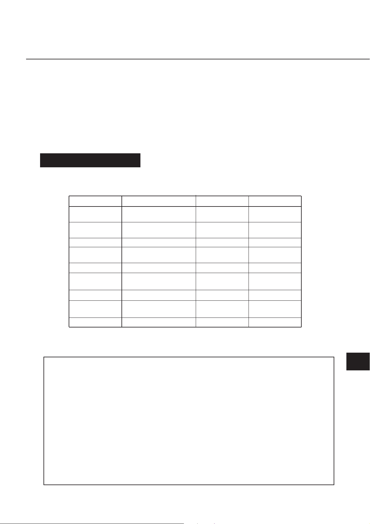
This projector applies the Projection Lenses listed below. Use the suitable lens for
where the projector is used.
✳ For installing those lenses, attaching Lens Mounting Adapters or removing Guide Pins is
required. Make sure the Model No. of the lens and the installation procedure on next pages
and be sure to install the lens precisely.
Model NO.
LNS-W01✳
LNS-W01Z
LNS-T01✳
LNS-T01Z
LNS-T02
LNS-W02✳
LNS-W02Z
LNS-M01✳
LNS-M01Z
LNS-S01✳
LNS-S02✳
LNS-S02Z
Type
Fixed Short Throw Lens
Fixed Long Throw Lens
Long Throw Zoom Lens
Short Throw Zoom Lens I
Semi-Long Throw
Zoom Lens
Standard Zoom Lens II
Standard Zoom Lens I
Zoom
Motor Driven
Fixed Manual
Focus
Fixed
Motor Driven
Motor Driven
Motor Driven
Motor Driven
Manual
Motor Driven
Motor Driven
Motor Driven
Motor Driven
Motor Driven
AVAILABLE LENS
LNS-W03
LNS-S03
Short Throw Zoom Lens II
Standard Zoom Lens III
Fixed
Manual
Motor Driven
Motor Driven
UPPER LENS COVER
- 2 -
E
NOTE : The installation procedure and needed parts
for lens installtaion depend on the type of the
Projection Lens. Check the Model No. of the
Projection Lens and be sure to install or replace the
lens following procedure below.
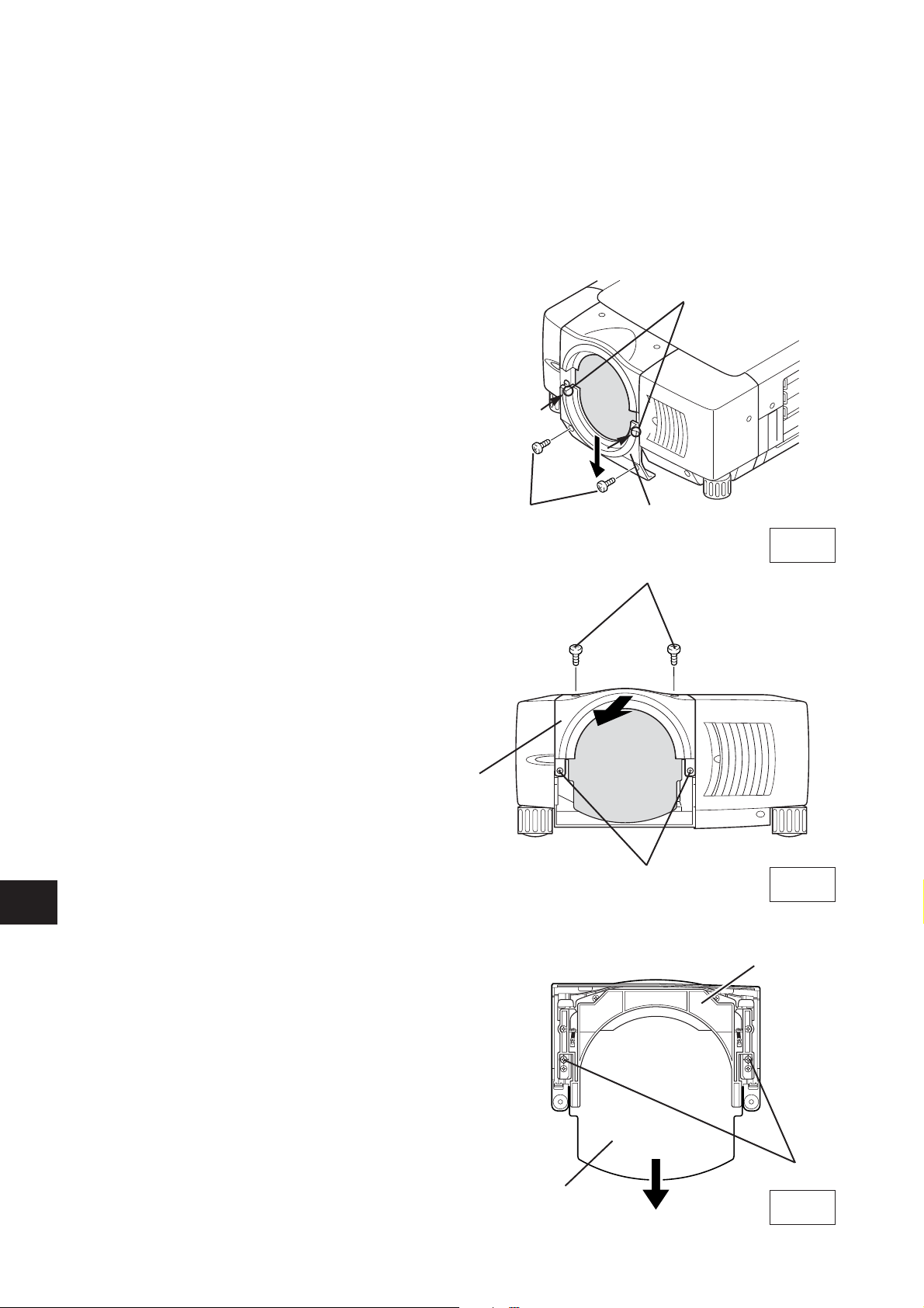
1
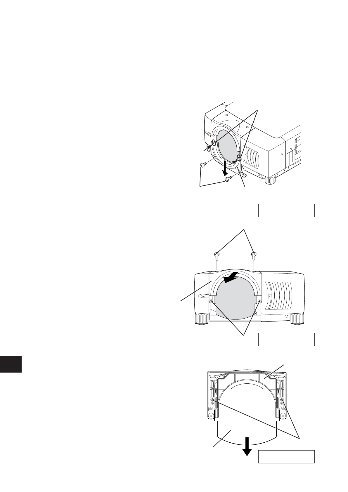
Remove Lower Lens Cover. Remove 2 Screws A.
Push part B and pull Lower Lens Cover down.
(See Fig. 1.)
2
Remove 4 Screws C. Pull Upper Lens Cover
toward front and remove. (See Fig. 2.)
3
Remove 2 Screws D and Cover Plate on the back
of Upper Lens Cover. (See Fig. 3.)
LENS REPLACEMENT AND INSTALLTION PROCEDURE
A
C
C
B
Fig-3
Fig-1
Fig-2
COVER PLATE
UPPER LENS COVER
LOWER LENS COVER
D
- 3 -
E
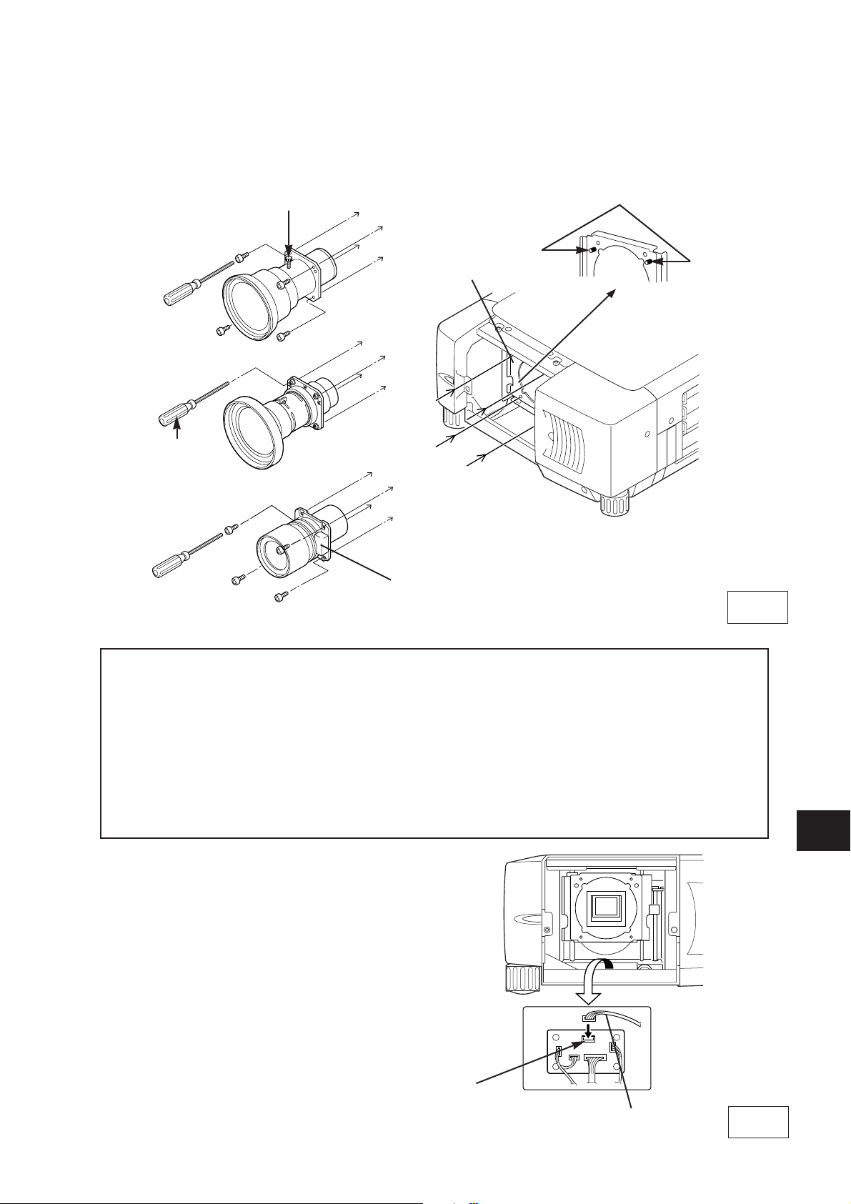
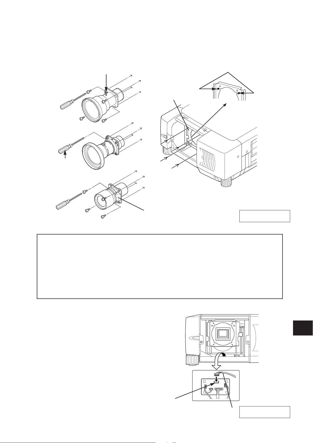
5
Connect Lens Motor Lead to the connector
"K96T" on the circuit board under the lens. (The
model with Lens Motor only.) Fix Lens Motor
Lead with the wire holder on the circuit board.
For installing the lenses listed below, attaching Lens Mounting Adapters is required. Before
mounting the lens, attach Lens Mounting Adapters. Refer to "LENS MOUNTING ADAPTER
INSTALLATION."
Model No.: LNS-W02, LNS-S01, LNS-M01
For installing the lenses listed below, removing Guide Pins is required. Before mounting the lens,
remove 2 Guide Pins from Lens Mounting Bracket. (See Fig. 4.)
Model No.: LNS-W01, LNS-S02, LNS-T01
4
Replace Lens Cap on the rear (mounting side) of Projection Lens and mount the lens on Lens
Mouting Bracket with 4 Screws. When installing the model with Lens Motor, be sure to mount the
lens with Lens Motor on the right. (See Fig. 4.)
GUIDE PIN
LENS LOCK
SCREW
Fig-4
DRIVER
IN THE LENS
LOCATE MOTOR
ON RIGHT SIDE
LENS MOUNTING
BLACKET
Fig-5
K96T
CONNECTOR
LENS MOTOR LEAD
Part No. (610 275 6029)
- 4 -
E
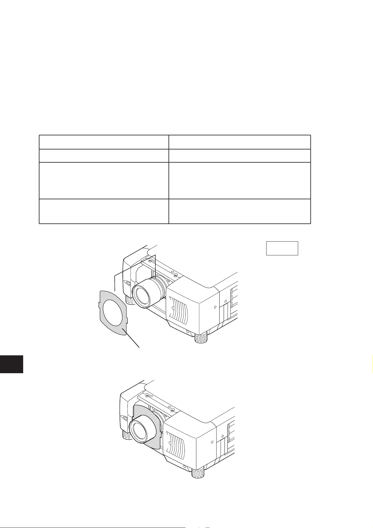
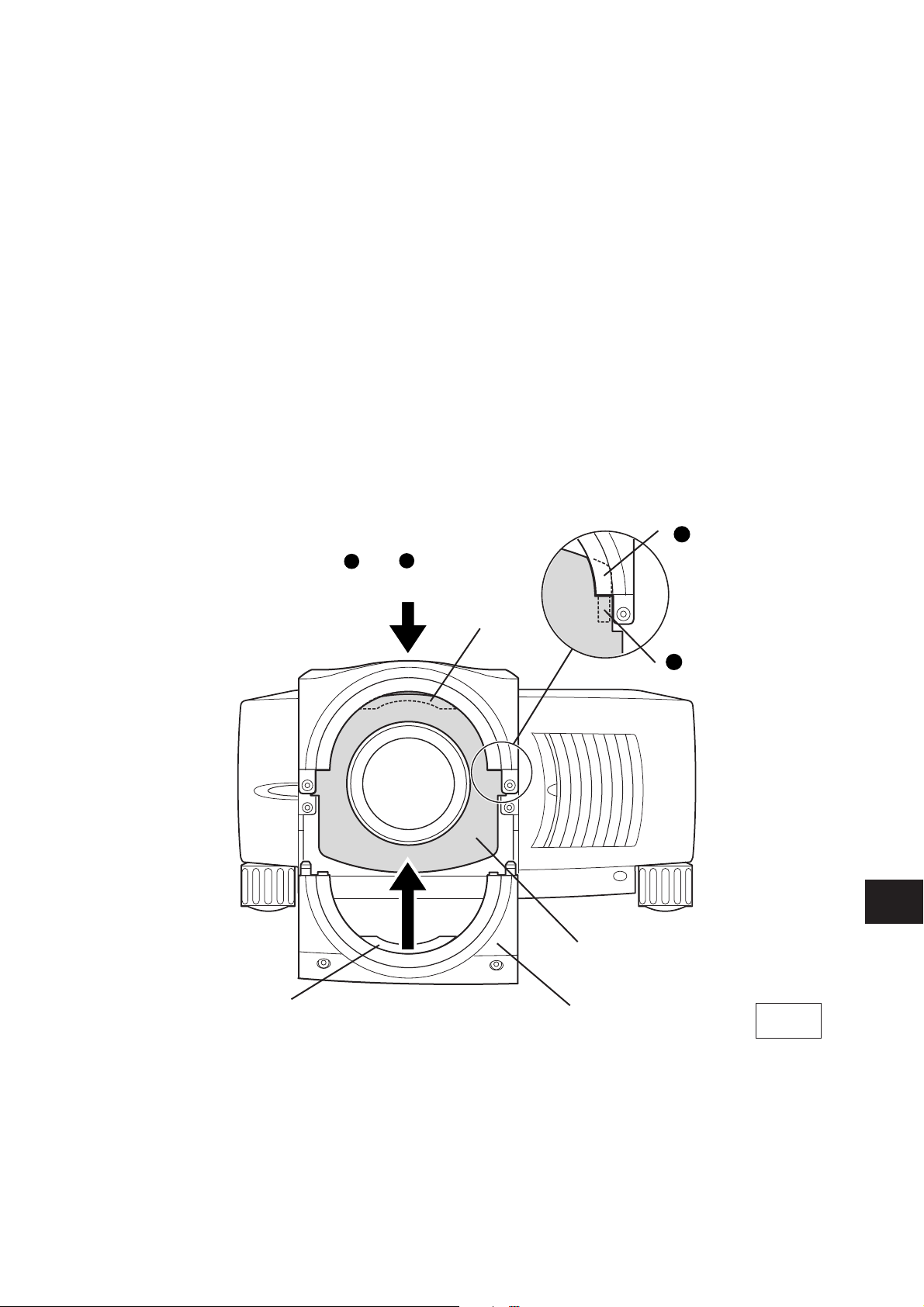
6
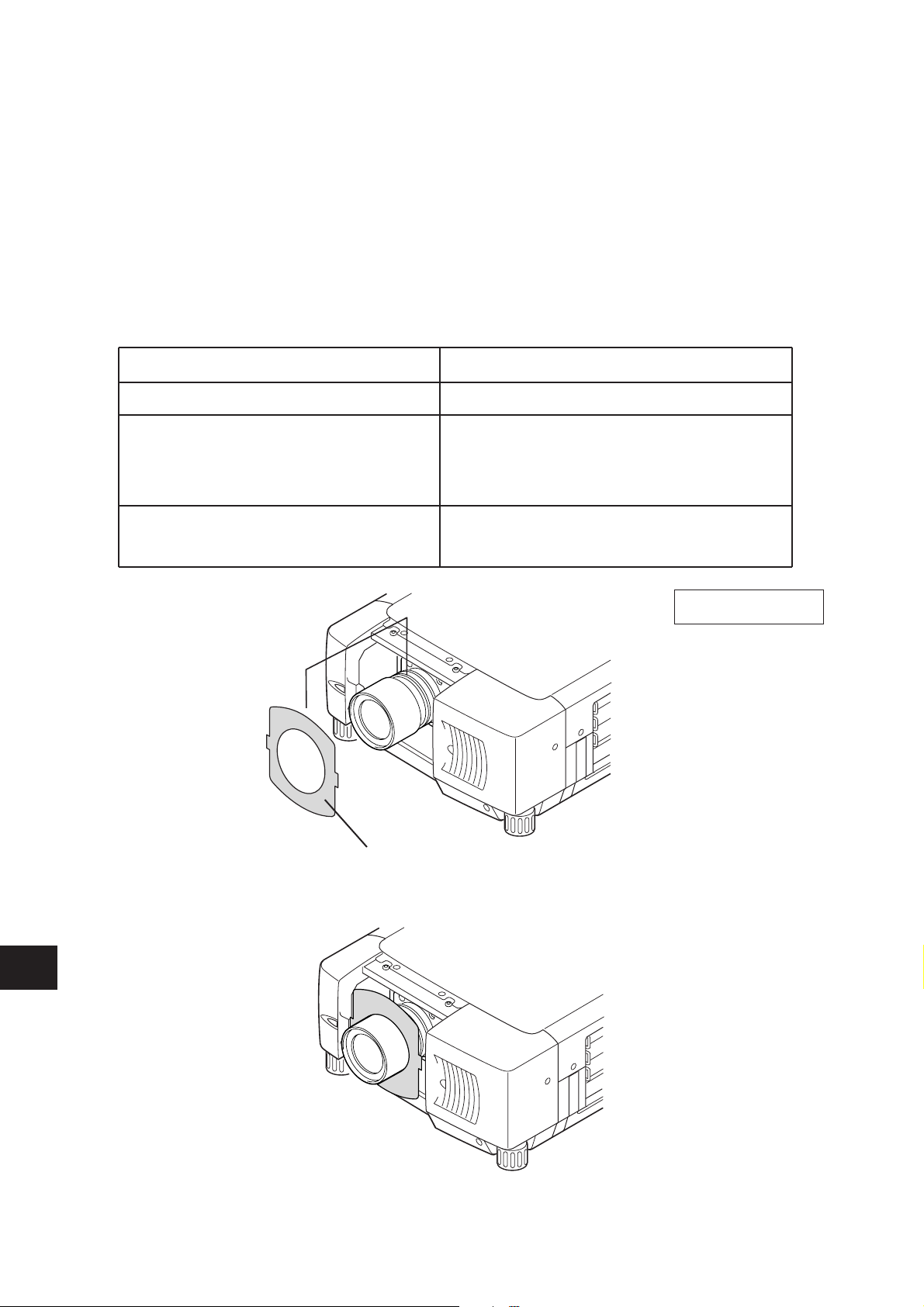
This projector has 3 Light-Block Sheets. Use Light-Block Sheet corresponding with lens. (Refer to
the list below.)
Set Light-Block Sheet through the lens.
Make sure the shape of Light-Block Sheets and be sure to set them as shown in the Fig. 6.
NOTE:
●
Be sure to set each Light-Block Sheets as shown in Fig-6.
●
Make sure the mark (TOP and BACK) on Light-Block Sheets and set them properly.
Light-Block Sheets For each lens.
Lens Model No.
LNS-S02, LNS-S02Z, LNS-S03
LNS-M01, LNS-T02, LNS-W02
LNS-M01Z, LNS-W02Z, LNS-S01
LNS-W03
LNS-W01, LNS-T01, LNS-W01Z
LNS-T01Z
Type No. (Part No.)
TYPE FD1 (610 290 9258)
TYPE FE1 (610 293 8937)
TYPE FF1 (610 293 8944)
Fig-6
LIGHT BLOCK SHEETS
Make sure the sheet figure and put
on proper position.
- 5 -
E
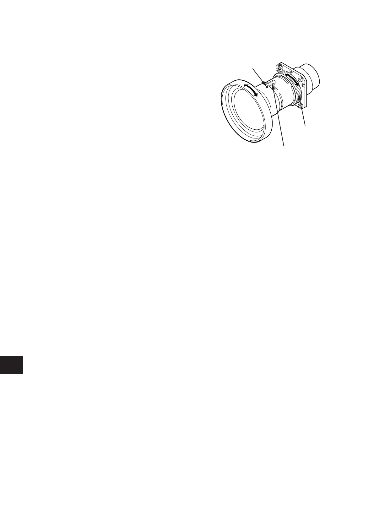
7
Adjust focus of the Projection Lens. (LNS-W01, LNS-W01Z, LNS-T01, LNS-T01Z and LNS-W03
only.) Set up the projector and project image on the screen. Loosen Focus Lens Lock Screw and
rotate Projection Lens to obtain proper focus. After adjusting focus, be sure to lock Projection Lens
with Focus Lens Lock Screw securely. (See Fig. 4.) Adjust focus of Projection Lens MODEL LNSW03, following Focus Adjustment on page 6.
8
Replace Upper Lens Cover. Slide Light-Block Sheets into the guide of Upper Lens Cover and set
them in front of the flap. (See Fig. 7.) Fix Upper Lens Cover with 4 Screws C. (See Fig. 2.)
9
Replace Lower Lens Cover. Slide Light-Block Sheets into the guide of Lower Lens Cover and set
them in front of the flap. (See Fig. 7.) Fix Lower Lens Cover with 2 Screws A. (See Fig. 1.)
10
Turn the projector on and operate Lens shift, Zoom and Focus fully to check Light-Block Sheets.
If Light-Block Sheets interfere with those operations, check Light-Block Sheets are set properly.
Fig-7
LOWER LENS
COVER
LIGHT-BLOCK
SHEETS
Slide into front
of the flap.
FLAP
Slide upper both side of LIGHT BLOCK
Sheets into between and
.
2
1
GUIDE
1
2
UPPER LENS
COVER
FLAP
- 6 -
E
Focus Lock Screw
Focus Lock Ring
● mark (yellow)
FOCUS ADJUSTMENT (For Model LNS-W03)
Set up the projector and project image on the screen.
1. Loosen the Focus Lock Screw on the projection
lens.
2. Rotate the projection lens to obtain proper focus
on center area of the screen.
When the distance of the screen and lens is 1 meter,
set ● mark (yellow) of the lens on Focus Lock Screw
position.
3. Lock the Focus Lock Screw securely.
When proper focus is not observed at outer area of
the screen, proceed following adjustments.
4. Loosen the Focus Lock Ring on the projection
lens. (Turn the Lock Ring to counter-clockwise.)
5. Rotate the lens to obtain proper focus on outer
area of the screen.
6. Lock the Focus Lock Ring securely. (Turn the Lock
Ring to clockwise.)
If proper focus is not observed entire screen, repeat
above adjustment 1~ 6.
- 7 -
E
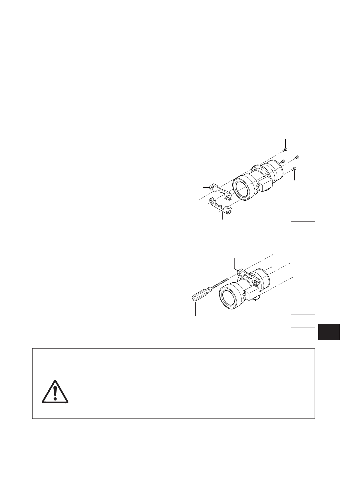
For installing the lenses listed below, attaching Lens Mounting Adapters is required.
Model No.: LNS-W02, LNS-S01, LNS-M01
1
Set Lens Mounting Adapters on the lens with 4
Screws. Use the round head screws.
(See Fig. 8.)
LENS MOUNTING ADAPTER INSTALLATION
Check the following parts supplied with the adapters.
ADAPTER SCREWS 8pcs.
(4 pcs. for mounting Adapters on the lens and 4 pcs. for mounting Lens on the projector.)
NOTE: Do not use the screws in the lens package.
2
Mount Projection Lens on the projector with 4
Screws supplied to the adapters. (See Fig. 9.)
BE SURE TO CHECK FOR SAFETY
After installing or replacing the lens, be sure to check the following for safety.
1. Check the lens is securely fixed with the screws.
2. Check no wiring is damaged or tangled on the gear of the lens motor or
the other mechanical parts.
3. Check no part is missing, or no mounting part is loose.
Fig-8
Fig-9
DRIVER IN THE LENS
C
A ADAPTER PART NO. 610 289 1676
B SCREW PART NO. 411 001 9303
C SCREW PART NO. 412 062 4009
✳1 PC NO.
ROUND HEAD SCREWS
ADAPTER
A
B
For installing the lens, “refer to LENS REPLACEMENT
AND INSTALLTION PROCEDURE.”
A
Some parts are not used for installation or replacement. Keep these parts for later use.
NOTE: Figures in this manual may be differ from the actual product.
- 8 -
E
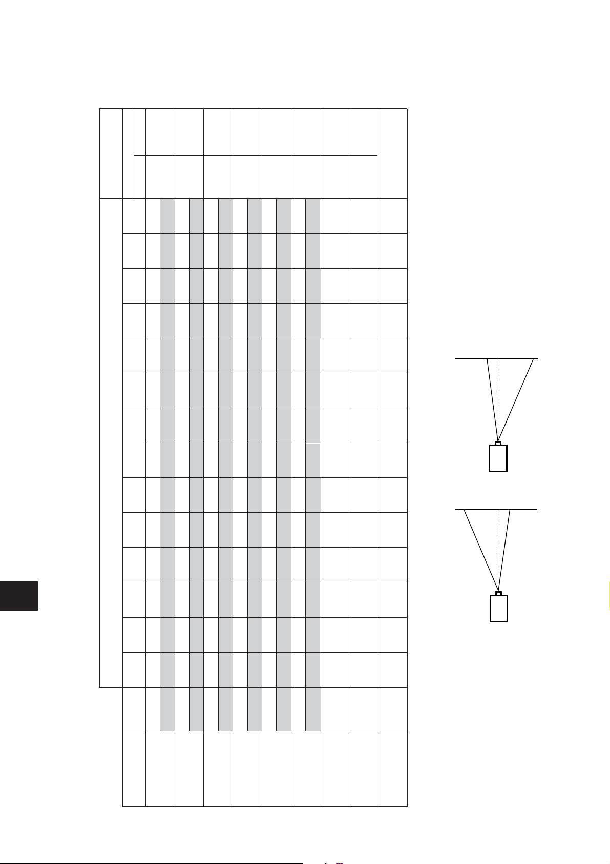
NOTE: Following tabe shows approximate measurement. Actual measurement depends on lens and projectors.
SPECIFICATIONS (Throw distance and screen size, screen of lens shift. )
Model No.
LNS-S02
LNS-S02Z
Zoom
40
60
80
100
120
150
180
200
250
300
350
400
500
600
LNS-W02
LNS-W02Z
LNS-T02
LNS-M01
LNS-M01Z
LNS-S01
LNS-W01
LNS-W01Z
LNS-T01
LNS-T01Z
MIN
MAX
MIN
MAX
MIN
MAX
MIN
MAX
MIN
MAX
NONE
NONE
1.9
1.5
1.4
1.1
5.1
3.8
3.6
2.9
2.3
1.5
3.0
2.4
2.1
1.7
7.5
5.5
5.4
4.3
3.5
2.2
4.1
3.2
2.9
2.3
10.0
7.3
7.2
5.7
4.6
2.9
5.2
4.0
3.6
2.9
12.5
9.1
9.0
7.1
5.8
3.7
6.3
4.9
4.4
3.4
14.9
10.8
10.8
8.5
7
4.4
7.9
6.1
5.5
4.3
18.6
13.5
13.5
10.5
8.8
5.6
9.6
7.4
6.7
5.2
22.3
16.1
16.2
12.6
10.6
6.7
10.7
8.3
7.4
5.8
24.8
17.9
18.0
14.0
11.8
7.4
13.4
10.4
9.3
7.2
31.0
22.3
22.5
17.5
14.8
9.3
16.1
12.5
11.2
8.6
37.1
26.7
27.0
21.0
17.8
11.2
18.9
14.6
13.1
10.1
43.3
31.1
31.5
34.4
20.8
13
21.6
16.7
15.0
11.5
49.5
35.5
36.0
27.9
23.8
14.9
27.1
20.9
13.7
14.4
61.8
44.3
45.0
34.9
29.7
18.6
32.5
25.1
22.5
17.3
74.2
53.1
54.0
41.8
35.7
22.4
0.9
5.6
1.4
8.4
1.9
11.2
2.4
14.0
2.9
16.8
3.6
21.0
4.4
25.3
4.9
28.1
6.1
35.1
7.4
42.1
8.6
49.2
9.9
56.2
12.3
70.3
14.8
84.3
U/D (MAX)
0
10
1
8
1
8
1
8
0
10
1
8
1
8
SCREEN SIZE (INCH) AND THROW DISTANCE (m)
LENS SHIFT/
CENTER RATIO
LENS SHIFT (UP/DOWN)
H2
H1
H2
H1
Upper max
Down max
0
10
LNS-W03
NONE
MIN
------
------
------
0.6
0.9
1.3
1.6
1.9
2.4
2.9
3.3
4.1
4.9
5.8
6.6
8.3
9.9
NONE
MAX
------
------
------
5.2
7.1
6.3
8.6
7.9
10.7
9.5
12.9
10.6
14.4
13.3
18.0
16.0
21.6
18.7
25.3
21.4
28.9
26.8
36.1
32.2
43.4
LNS-S03
H1
H2
LNS-S03
Lentille III de zoom standard
Moteur entraîné Moteur entraîné
- 1 -
F
PROJECTEUR A LCD
PROCEDURES D’INSTALLATION ET DE REMPLACEMENT DE
LA LENTILLE
ATTENTION
● FEUILLES DE BLOCAGE LEGER 3 unités
● ADAPTATEURS DE MONTAGE DE LENTILLE 2 unités
● VIS D’ADAPTATEURS 8 unités
Ce projecteur accepte les lentilles de projection mentionnées dans la liste ci-dessous.
Utilisez la lentille convenant à l’endroit où vous utilisez le projecteur.
✳ Pour installer ces lentilles, il faut fixer les adaptateurs de montage de lentille ou retirer les
broches du guide. Vérifiez le n° de modèle de la lentille et la procédure d’installation aux
pages suivantes et veillez à installer précisément la lentille.
N° de modèle
LNS-W01✳
LNS-W01Z
LNS-T01✳
LNS-T01Z
LNS-T02
LNS-W02✳
LNS-W02Z
LNS-M01✳
LNS-M01Z
LNS-S01✳
LNS-S02✳
LNS-S02Z
Type
Lentille pour projection
courte fixe
Lentille pour projection
longue fixe
Lentille I de zoom pour
projection courte
Lentille de zoom pour
projection semi-longue
Lentille II de zoom standard
Lentille I de zoom standard
Zoom
Moteur entraîné
Fixe Manuel
Mise au point
Fixe
Moteur entraîné
Moteur entraîné
Moteur entraîné
Moteur entraîné
Manuel
Moteur entraîné
Moteur entraîné
Moteur entraîné
Moteur entraîné
Moteur entraîné
LNS-W03
Lentille II de zoom pour
projection courte
Fixe Manuel
LENTILLE UTILISABLE
Lorsque vous installez ou que vous remplacez la lentille de projection, reportezvous à ce manuel. Pour l’installation de la lentille, utilisez les pièces indiquées dans
ce manuel. N’utilisez pas le manuel d’installation et les feuilles de blocage léger
contenus dans l’emballage de la lentille.
Vérifiez les pièces suivantes fournies avec ce projecteur.
Lentille de zoom pour
projection longue
REMARQUES CONCERNANT L’INSTALLATION DE LA LENTILLE
●
L’installation et le remplacement de la lentille doivent être confiés à un technicien
d’entretien qualifié.
●
Veillez à installer la lentille en suivant rigoureusement la procédure.
●
Ne touchez ou ne retirez aucune pièce à l’exception de la lentille et des pièces connexes.
Sinon, vous risquerez de produire des anomalies, une électrocution, un incendie ou
d’autres accidents.
●
Avant d’installer ou de remplacer la lentille, assurez-vous que le n° de modèle de la lentille
de projection correspond bien au projecteur.
●
Lorsque vous déplacez ou que vous installez le projecteur, veillez à remettre en place le
capuchon de lentille pour protéger la surface de la lentille. Veillez aussi à ne pas saisir ou
manipuler la lentille avec une force excessive. Sinon, vous pourriez endommager la
lentille, le coffret ou les composants mécaniques de l’appareil.
●
Pour plus de détails concernant la lentille et son installation, adressez-vous au revendeur
chez qui vous avez acheté le projecteur.
CAPUCHON DE
LENTILLE SUPERIEUR
A
C
C
B
COUVERCLE
CAPUCHON DE
LENTILLE SUPERIEUR
CAPUCHON DE
LENTILLE INFERIEUR
D
- 2 -
F
1
Retirez le capuchon de lentille inférieur. Retirez 2
vis A. Poussez la partie B et tirez le capuchon de
lentille inférieur vers le bas. (Reportez-vous à
l’illustration 1.)
2
Retirez 4 vis C. Tirez le capuchon de lentille
supérieur vers l’avant et enlevez-le. (Reportezvous à l’illustration 2.)
3
Retirez les 2 vis D et le couvercle situé à l’arrière
du capuchon de lentille supérieure. (Reportezvous à l’illustration 3.)
PROCEDURE D’INSTALLATION ET DE REMPLACEMENT DE LA LENTILLE
Illustration 1
Illustration 2
Illustration 3
REMARQUE: La procédure d’installation et les
pièces nécessaires pour l’installation de la lentille
dépendent du type de la lentille de projection.
Vérifiez le n° de modèle de la lentille de projection,
et veillez à installer ou remplacer la lentille en
procédant comme indiqué ci-dessous.
BROCHE DU GUIDE
VIS DE VERROUILLAGE
DE LA LENTILLE
TOURNEVIS POUR
LA LENTILLE
PLACEZ LE MOTEUR
SUR LE COTE DROIT
SUPPORT DE
MONTAGE
DE LENTILLE
CONNECTEUR K96T
FIL DE MOTEUR DE LENTILLE
N° de pièce
(610 275 6029)
- 3 -
F
5
Connectez le fil du moteur de lentille au
connecteur “K96T” de la carte de circuits sous la
lentille. (Modèle avec moteur de lentille
seulement) Fixez le fil de moteur de lentille avec
le serre-fils sur la carte de circuits.
Pour installer les lentilles mentionnées ci-dessous, il faut fixer les adaptateurs de montage de
lentille. Avant de monter la lentille, fixez les adaptateurs de montage de lentille. Reportez-vous à la
section “INSTALLATION DES ADAPTATEURS DE MONTAGE DE LENTILLE”.
N° de modèle: LNS-W02, LNS-S01, LNS-M01
Pour installer les lentilles mentionnées ci-dessous, il faut retirer les broches du guide. Avant de
monter la lentille, retirez les 2 broches du guide du support de montage de lentille. (Reportez-vous
à l’illustration 4.)
N° de modèle: LNS-W01, LNS-S02, LNS-T01
4
Remettez le capuchon de lentille à l’arrière (côté de montage) de la lentille de projection et montez
la lentille sur le support de montage de lentille à l’aide des 4 vis. Lorsque vous installez le modèle
avec moteur de lentille, veillez à monter la lentille avec le moteur de lentille placé à droite.
(Reportez-vous à l’illustration 4.)
Illustration 4
Illustration 5
- 4 -
F
6
Ce projecteur est équipé de 3 feuilles de blocage léger. Utilisez la feuille de blocage léger
correspondant à la lentille. (Reportez-vous à la liste ci-dessous.)
Placez la feuille de blocage léger en travers de la lentille.
Vérifiez bien la forme des feuilles de blocage léger et veillez à les fixer comme indiqué sur
l’illustration 6.
REMARQUE:
●
Veillez à placer chaque feuille de blocage léger comme indiqué sur l’illustration 6.
●
Vérifiez les repères (TOP et BACK) marqués sur les feuilles de blocage léger, et mettez-les
correctement en place.
Illustration 6
FEUILLES DE BLOCAGE LEGER
Vérifiez bien le numéro des feuilles
et placez-les en position correcte.
Feuilles de blocage léger pour chaque lentille.
Número de modelo de objetivo
LNS-S02, LNS-S02Z, LNS-S03
LNS-M01, LNS-T02, LNS-W02
LNS-M01Z, LNS-W02Z, LNS-S01
LNS-W03
LNS-W01, LNS-T01, LNS-W01Z
LNS-T01Z
N° de modèle de lentille
TYPE FD1 (610 290 9258)
TYPE FE1 (610 293 8937)
TYPE FF1 (610 293 8944)
 Loading...