

Page 1
Hybrid IP-PBX
Feature Manual
Thank you for purchasing a Panasonic Hybrid IP-PBX.
Please read this manual carefully before using this product and save this manual for future use.
KX-TDA50: PSMPR Software File Version 5.0000 or later
KX-TDA100/KX-TDA200: PMPR Software File Version 5.0000 or later
KX-TDA600: PLMPR Software File Version 5.0000 or later
Document Version: 2008-11
KX-TDA50/KX-TDA100
Model No. KX-TDA200/KX-TDA600
Page 2

Introduction
Introduction
About the Feature Manual
The Feature Manual is designed to serve as an overall reference describing the features of the Panasonic
Hybrid IP-PBX. It explains what the PBX can do, as well as how to obtain the most of its many features and
facilities.
The Feature Manual is divided into the following sections:
Sections 1 to 20, Features and Configurations
Describes the call handling, system configuration and administration features of the PBX.
Section 21, Appendix
Provides tables listing capacity of system resources, exclusive features for each PBX model, tone and ring
tone tables, and the revision history of this Feature Manual.
Index
An alphabetical listing of features and terms, as well as the page numbers of related sections.
References Found in the Feature Manual
Installation Manual References
The PBX Installation Manual provides instructions detailing the installation and maintenance of the PBX.
Sections from the Installation Manual are listed throughout the Feature Manual for your reference.
PC Programming Manual References
Commonly
These PC programming items are noted throughout the Feature Manual for your reference by title and System
Menu number.
used settings can be programmed using the Maintenance Console (® 13.1.6 PC Programming).
PT Programming Manual References
Commonly used settings can be programmed using a display PT (® 13.1.28 PT Programming). These PT
programming items are noted throughout the Feature Manual for your reference by title and program number.
Feature Manual References
Related sections of the Feature Manual are listed for your reference.
Operating Manual References
The PBX Operating Manual describes how users can access commonly used PBX features and functions with
their proprietary telephones (PTs), single line telephones (SLTs), portable stations (PSs), and DSS Consoles.
Sections from the Operating Manual are listed throughout the Feature Manual for your reference.
Links to Other Pages and Manuals
If viewing this Feature Manual with a PC, certain items are linked to different sections of the Feature Manual
and other PBX manuals. Click on a link to jump to that section.
Linked items include:
• Installation Manual References
• Feature Manual References
• Operating Manual References
• PT Programming References
• PC Programming References
2 Feature Manual Document Version 2008-11
Page 3

Introduction
Abbreviations
There are many abbreviations used in this manual (e.g., "PT", for proprietary telephone). Please refer to the
list in the next section for the meaning of each abbreviation.
Note
• The contents of this manual apply to PBXs with a certain software version, as indicated on the cover
of this manual. To confirm the software version of your PBX, see 2.7.1 Frequently Asked Questions
in the FAQ of the PC Programming Manual, or [190] Main Processing (MPR) Software Version
(FAQ)
Reference in the PT Programming Manual.
• Some optional service cards, PTs, and features are not available in some areas. In the same respect,
some optional service cards and features are available exclusively for the KX-TDA50, KX-TDA100,
KX-TDA200, or KX-TDA600. Please consult your certified Panasonic dealer for more information.
® 21.2 Exclusive Features Table
• Product specifications are subject to change without notice. In some cases, additional information,
including updates to this and other manuals, is included in the Maintenance Console’s Information
before programming. Install the latest version of Maintenance Console to view this information.
• In this manual, model number suffixes (e.g., KX-TDA50G) are omitted unless necessary.
• All system programming can be performed through PC programming (® 13.1.6 PC Programming).
However, only a subset can be performed through PT programming (® 13.1.28 PT Programming).
Throughout this manual, programming references are included as follows:
PC Programming
The number within the brackets indicates the System Menu number for the Maintenance Console.
® 8.1 [6-1] System Speed Dial—
PT Programming
The number within the brackets indicates the programming number that is entered when performing
PT programming.
® [001] System Speed Dialing Number
For further details, please refer to the PC Programming Manual and PT Programming Manual.
CO Line Access Number + Telephone Number
Safety Notices
Please
damage to property.
The notices are classified as follows, according to the severity of injury or damage:
WARNING
observe the safety notices in this manual in order to avoid danger to users or other people, and prevent
WARNING
CAUTION
Unplug the PBX from the AC outlet if it emits smoke, an abnormal smell or makes unusual noise.
These
authorized Panasonic Factory Service Center.
conditions can cause fire or electric shock. Confirm that smoke has stopped and contact an
This notice means that misuse could result in death or serious injury.
This notice means that misuse could result in injury or damage to property.
Trademarks
• Microsoft and Outlook are either registered trademarks or trademarks of Microsoft Corporation in the United
States and/or other countries.
• The Bluetooth
Panasonic Corporation is under license.
• All other trademarks identified herein are the property of their respective owners.
®
word mark and logos are owned by the Bluetooth SIG, Inc. and any use of such marks by
Document Version 2008-11 Feature Manual 3
Page 4

Introduction
Feature Highlights
Networking Features
The PBX supports the following private networking features:
TIE Line Service
PBXs can be connected via a privately leased telephone lines, forming a private network. These "TIE lines"
provide a cost-effective way to route calls and communications, and are often used to connect corporate
offices located in different cities.
(® 13.1.13 PRIVATE NETWORK FEATURES)
QSIG Support
TIE line service can be used on a private network that is established using Voice over Internet Protocol
(VoIP) with the IP-GW card, or ISDN (PRI) lines programmed to implement the QSIG protocol (Q.931).
QSIG offers TIE line service as well as advanced caller and called party identification features.
(® 13.1.18 PRIVATE NETWORK FEATURES—QSIG)
Voice over Internet Protocol (VoIP) Support
The PBX can be used on a private network which implements VoIP. On this type of network, information
is sent over the private network in IP packets, which allows voice as well as data to be sent to other devices
in the private network. Automatic rerouting of VoIP calls to public CO lines is also available in case of
network difficulties.
(® 13.1.23 Private Network Features—VoIP (Voice over Internet Protocol))
Built-in Small Call Center Features
Extensions can form an incoming call distribution (ICD) group and be used as a small call center which can
take advantage of several features, some of which are highlighted below.
Queuing
When all available extensions in an ICD group are busy, additional calls can be placed in a queue as they
arrive. While calls are waiting in the queue, callers can hear background music (BGM), an outgoing
message (OGM), etc.
(® 9.1.6 ICD Group Features—Queuing)
Log-in/Log-out
Members of an ICD group can log-in to or log-out of a group manually. Group members can log-in at the
beginning of a work shift, and log-out at the end of the day. While logged-in, ICD group members can be
allotted a specified amount of time after completing a call during which new calls will not be received by
their extensions, allowing them to finish any necessary paperwork before being eligible to receive new calls
(Wrap-up).
(® 9.1.3 ICD Group Features—Log-in/Log-out)
VIP Call
The VIP Call feature is one method of making sure that calls from preferred customers or callers are
answered quickly. When using VIP Call mode, ICD groups are assigned a priority, allowing calls in
higher-priority groups to be answered before calls in lower-priority groups.
(® 9.1.8 ICD Group Features—VIP Call)
Computer Telephony Integration (CTI) Features
Computers can be connected to the PBX to provide extension users with access to advanced features such
as pop-up display of caller information, computer-based speed dialing, etc.
(® 3.1.21 CTI (Computer Telephony Integration))
PC Phone/PC Console
These Panasonic CTI applications can be used on computers connected to each extension, providing their
respective extension users with powerful and flexible call handling and display features.
(® 13.1.5 PC Console/PC Phone)
4 Feature Manual Document Version 2008-11
Page 5

Introduction
Third Party CTI Applications
The PBX supports industry standard protocols, allowing third-party CTI applications to be integrated with
the PBX and its extensions.
Voice Mail Features
A Voice Processing System (VPS) can be connected to the PBX to provide Voice Mail (VM) and Automated
Attendant (AA) services. A Panasonic VPS which supports DPT (Digital) Integration can be connected to the
PBX
effortlessly and with minimal setup required. It can also be connected to one PBX in a network to provide
voice mail services for extensions at all PBXs. Conventional DTMF (analog) voice mail systems, including
those from other manufacturers, are also supported.
(® 19.1.3 Voice Mail (VM) Group)
Paralleled Telephone Features
By connecting telephones in parallel, you can increase the number of telephones connected to the PBX without
adding additional extension cards.
(® 13.1.2 Paralleled Telephone)
Parallel Mode
An SLT can be connected to an analog proprietary telephone (APT) or digital proprietary telephone (DPT)
that is connected to a Super Hybrid port of the PBX. The SLT shares the same extension number with the
APT or DPT.
EXtra Device Port (XDP) Mode
An SLT can be connected to a DPT that is connected to a Super Hybrid port of the PBX. Unlike parallel
mode, XDP mode allows each telephone to act as an independent extension with its own extension
number.
Digital XDP
A DPT can be connected to another DPT that is connected to a DPT port or a Super Hybrid port of the
PBX. Similar to XDP mode, each DPT acts as an independent extension with its own extension number.
Portable Station (PS) Features
A Panasonic PS (e.g., KX-TD7680, KX-TD7690) can be used in place of a PT to provide wireless access to
PBX features and call handling. When in Wireless XDP Parallel Mode, a PS can share an extension number
with a wired telephone, allowing extension users to use their PSs when they are away from their desks to
answer or make calls as if they were using their wired telephones.
Hospitality Features
This PBX has several features that support its use in a hotel-type environment. Extensions corresponding to
guest rooms can be "checked in" or "checked out" by a designated hotel operator, who can also check or set
wake-up calls.
(® 8.1.4 HOSPITALITY FEATURES)
Simplified Voice Message (SVM) Features
By just installing an optional voice message card in the PBX, simple answering machine services can be
provided.
(® 16.1.5 SVM (Simplified Voice Message))
Document Version 2008-11 Feature Manual 5
Page 6

List of Abbreviations
List of Abbreviations
A
AA
Automated Attendant
ACD
Automatic Call Distribution
ANI
Automatic Number Identification
APT
Analog Proprietary Telephone
ARS
Automatic Route Selection
B
BGM
Background Music
C
CCBS
Completion of Calls to Busy Subscriber
CF
Call Forwarding
CLI
Calling Line Identification
CLIP
Calling Line Identification Presentation
CLIR
Calling Line Identification Restriction
CNIP
Calling Name Identification Presentation
CNIR
Calling Name Identification Restriction
COLP
Connected Line Identification Presentation
COLR
Connected Line Identification Restriction
CONP
Connected Name Identification Presentation
CONR
Connected Name Identification Restriction
COS
Class of Service
—QSIG
CPC
Calling Party Control
CS
Cell Station
CT
Call Transfer—QSIG
CTI
Computer Telephony Integration
D
DID
Direct Inward Dialing
DIL
Direct In Line
DISA
Direct Inward System Access
DND
Do Not Disturb
DPT
Digital Proprietary Telephone
DSS
Direct Station Selection
DTMF
Dual Tone Multi-Frequency
E
EFA
External Feature Access
F
FWD
Call Forwarding
G
G-CO
Group-CO
I
ICD
Incoming Call Distribution
6 Feature Manual Document Version 2008-11
Page 7

List of Abbreviations
IP-PT
IP Proprietary Telephone
IRNA
Intercept Routing—No Answer
ISDN
Integrated Services Digital Network
L
L-CO
Loop-CO
LCS
Live Call Screening
LED
Light Emitting Diode
N
NDSS
Network Direct Station Selection
O
SLT
Single Line Telephone
SMDR
Station Message Detail Recording
SVM
Simplified Voice Message
T
TAFAS
Trunk Answer from Any Station
TEI
Terminal Endpoint Identifier
TRG
Trunk Group
TRS
Toll Restriction
U
UCD
Uniform Call Distribution
OGM
Outgoing Message
OHCA
Off-hook Call Announcement
OPX
Off Premise Extension
P
PDN
Primary Directory Number
PIN
Personal Identification Number
PRI
Primary Rate Interface
PS
Portable Station
PT
Proprietary Telephone
S
V
VM
Voice Mail
VoIP
Voice over Internet Protocol
VPS
Voice Processing System
X
XDP
EXtra Device Port
S-CO
Single-CO
SDN
Secondary Directory Number
Document Version 2008-11 Feature Manual 7
Page 8

Table of Contents
Table of Contents
1
Features and Configurations—A ..........................................................13
1.1 A ........................................................................................................................................14
1.1.1 Absent Message .............................................................................................................14
1.1.2 Account Code Entry .......................................................................................................15
1.1.3 ARS (Automatic Route Selection) ..................................................................................16
1.1.4 Automatic Callback Busy (Camp-on) .............................................................................22
1.1.5 Automatic Extension Release ........................................................................................23
1.1.6 Automatic Fax Transfer ..................................................................................................23
1.1.7 Automatic Time Adjustment ...........................................................................................24
2 Features and Configurations—B ..........................................................27
2.1 B ........................................................................................................................................28
2.1.1 BGM (Background Music) ..............................................................................................28
3 Features and Configurations—C ..........................................................31
3.1 C ........................................................................................................................................32
3.1.1 Caller ID .........................................................................................................................32
3.1.2 Call Hold .........................................................................................................................36
3.1.3 Call Log, Incoming ..........................................................................................................38
3.1.4 Call Monitor ....................................................................................................................41
3.1.5 Call Park .........................................................................................................................43
3.1.6 Call Pickup .....................................................................................................................44
3.1.7 Call Splitting ...................................................................................................................45
3.1.8 Call Transfer ...................................................................................................................46
3.1.9 CALL WAITING FEATURES ..........................................................................................49
3.1.10 Call Waiting Tone ...........................................................................................................51
3.1.11 CELLULAR PHONE FEATURES ...................................................................................52
3.1.12 CLI (Calling Line Identification) Distribution ...................................................................52
3.1.13 CLIP (Calling Line Identification Presentation) ...............................................................54
3.1.14 CO Line Access ..............................................................................................................56
3.1.15 CO Line Call Limitation ...................................................................................................58
3.1.16 Conference .....................................................................................................................59
3.1.17 Confirmation Tone ..........................................................................................................60
3.1.18 Consultation Hold ...........................................................................................................61
3.1.19 COS (Class of Service) ..................................................................................................62
3.1.20 CPC (Calling Party Control) Signal Detection ................................................................63
3.1.21 CTI (Computer Telephony Integration) ...........................................................................63
4 Features and Configurations—D ..........................................................67
4.1 D ........................................................................................................................................68
4.1.1 Data Line Security ..........................................................................................................68
4.1.2 Dial Mode Selection .......................................................................................................68
4.1.3 Dial Tone ........................................................................................................................69
4.1.4 Dial Tone Transfer ..........................................................................................................70
4.1.5 DID (Direct Inward Dialing) .............................................................................................71
4.1.6 DIL (Direct In Line) .........................................................................................................73
4.1.7 DISA (Direct Inward System Access) .............................................................................75
4.1.8 Display Information .........................................................................................................85
4.1.9 DND (Do Not Disturb) .....................................................................................................86
4.1.10 Door Open ......................................................................................................................87
4.1.11 Doorphone Call ..............................................................................................................88
8 Feature Manual Document Version 2008-11
Page 9

Table of Contents
5 Features and Configurations—E ..........................................................91
5.1 E ........................................................................................................................................92
5.1.1 EFA (External Feature Access) ......................................................................................92
5.1.2 Emergency Call ..............................................................................................................93
5.1.3 Executive Busy Override ................................................................................................93
5.1.4 Extension Dial Lock ........................................................................................................94
5.1.5 Extension Feature Clear .................................................................................................95
5.1.6 Extension PIN (Personal Identification Number) ............................................................96
5.1.7 Extension Port Configuration ..........................................................................................97
5.1.8 External Relay ................................................................................................................99
5.1.9 External Sensor ............................................................................................................100
6 Features and Configurations—F ........................................................103
6.1 F ......................................................................................................................................104
6.1.1 Fixed Buttons ...............................................................................................................104
6.1.2 Flash/Recall/Terminate ................................................................................................106
6.1.3 Flexible Buttons ............................................................................................................107
6.1.4 Flexible Numbering/Fixed Numbering ..........................................................................109
6.1.5 Floating Extension ........................................................................................................116
6.1.6 FWD (Call Forwarding) .................................................................................................117
6.1.7 FWD/DND Button, Group FWD Button ........................................................................121
7 Features and Configurations—G ........................................................125
7.1 G .....................................................................................................................................126
7.1.1 GROUP FEATURES ....................................................................................................126
8 Features and Configurations—H ........................................................131
8.1 H ......................................................................................................................................132
8.1.1 Hands-free Answerback ...............................................................................................132
8.1.2 Hands-free Operation ...................................................................................................133
8.1.3 Headset Operation .......................................................................................................133
8.1.4 HOSPITALITY FEATURES ..........................................................................................134
8.1.5 Host PBX Access Code (Access Code to the Telephone Company from a Host
PBX) .............................................................................................................................134
8.1.6 Hot Line ........................................................................................................................136
9 Features and Configurations—I ..........................................................139
9.1 I .......................................................................................................................................140
9.1.1 ICD GROUP FEATURES .............................................................................................140
9.1.2 ICD Group Features—Group Call Distribution .............................................................143
9.1.3 ICD Group Features—Log-in/Log-out ..........................................................................146
9.1.4 ICD Group Features—Outside Destinations ................................................................149
9.1.5 ICD Group Features—Overflow ...................................................................................151
9.1.6 ICD Group Features—Queuing ....................................................................................153
9.1.7 ICD Group Features—Supervisory ..............................................................................155
9.1.8 ICD Group Features—VIP Call ....................................................................................157
9.1.9 Idle Extension Hunting .................................................................................................158
9.1.10 INCOMING CALL FEATURES .....................................................................................160
9.1.11 Intercept Routing ..........................................................................................................163
9.1.12 Intercept Routing—No Destination ...............................................................................167
9.1.13 Intercom Call ................................................................................................................168
9.1.14 Internal Call Block ........................................................................................................169
9.1.15 IP-PT (IP Proprietary Telephone) .................................................................................171
9.1.16 ISDN (INTEGRATED SERVICES DIGITAL NETWORK) FEATURES ........................172
Document Version 2008-11 Feature Manual 9
Page 10

Table of Contents
10 Features and Configurations—L ........................................................175
10.1 L ......................................................................................................................................176
10.1.1 LED Indication ..............................................................................................................176
10.1.2 Line Preference—Incoming ..........................................................................................178
10.1.3 Line Preference—Outgoing ..........................................................................................179
10.1.4 Local Alarm Information ...............................................................................................180
11 Features and Configurations—M ........................................................183
11.1 M .....................................................................................................................................184
11.1.1 Manager Features ........................................................................................................184
11.1.2 MEMORY DIALING FEATURES ..................................................................................185
11.1.3 Message Waiting ..........................................................................................................187
11.1.4 Music on Hold ...............................................................................................................191
11.1.5 Mute .............................................................................................................................192
12 Features and Configurations—O ........................................................193
12.1 O .....................................................................................................................................194
12.1.1 Off-hook Monitor ...........................................................................................................194
12.1.2 OGM (Outgoing Message) ...........................................................................................194
12.1.3 OHCA (Off-hook Call Announcement) .........................................................................197
12.1.4 One-touch Dialing .........................................................................................................197
12.1.5 Operator Features ........................................................................................................198
13 Features and Configurations—P ........................................................201
13.1 P ......................................................................................................................................202
13.1.1 Paging ..........................................................................................................................202
13.1.2 Paralleled Telephone ...................................................................................................204
13.1.3 Password Security ........................................................................................................207
13.1.4 Pause Insertion ............................................................................................................208
13.1.5 PC Console/PC Phone .................................................................................................209
13.1.6 PC Programming ..........................................................................................................210
13.1.7 PDN (Primary Directory Number)/SDN (Secondary Directory Number)
Extension ......................................................................................................................213
13.1.8 Power Failure Restart ...................................................................................................218
13.1.9 Power Failure Transfer .................................................................................................218
13.1.10 Predialing .....................................................................................................................220
13.1.11 Printing Message ..........................................................................................................220
13.1.12 Privacy Release ...........................................................................................................221
13.1.13 PRIVATE NETWORK FEATURES ..............................................................................221
13.1.14 Private Network Features—Centralized Voice Mail .....................................................242
13.1.15 Private Network Features—NDSS (Network Direct Station Selection) ........................246
13.1.16 Private Network Features—Network ICD Group ..........................................................251
13.1.17 Private Network Features—PS Roaming by Network ICD Group ................................252
13.1.18 PRIVATE NETWORK FEATURES—QSIG ..................................................................253
13.1.19 Private Network Features—QSIG—CCBS (Completion of Calls to Busy
Subscriber) ...................................................................................................................255
13.1.20 Private Network Features—QSIG—CF (Call Forwarding) ...........................................256
13.1.21 Private Network Features—QSIG—CLIP/COLP (Calling/Connected Line Identification
Presentation) and CNIP/CONP (Calling/Connected Name Identification
Presentation) ................................................................................................................257
13.1.22 Private Network Features—QSIG—CT (Call Transfer) ................................................259
13.1.23 Private Network Features—VoIP (Voice over Internet Protocol) ..................................261
13.1.24 PS Connection .............................................................................................................263
13.1.25 PS Directory .................................................................................................................265
10 Feature Manual Document Version 2008-11
Page 11

Table of Contents
13.1.26 PS Feature Buttons ......................................................................................................266
13.1.27 PS Ring Group .............................................................................................................266
13.1.28 PT Programming ..........................................................................................................270
14 Features and Configurations—Q ........................................................273
14.1 Q .....................................................................................................................................274
14.1.1 Quick Dialing ................................................................................................................274
14.1.2 Quick Setup ..................................................................................................................275
15 Features and Configurations—R ........................................................277
15.1 R ......................................................................................................................................278
15.1.1 Redial, Last Number .....................................................................................................278
15.1.2 Ring Tone Pattern Selection ........................................................................................279
15.1.3 Room Status Control ....................................................................................................281
16 Features and Configurations—S ........................................................283
16.1 S ......................................................................................................................................284
16.1.1 SMDR (Station Message Detail Recording) .................................................................284
16.1.2 Special Carrier Access Code .......................................................................................291
16.1.3 Speed Dialing, Personal ...............................................................................................291
16.1.4 Speed Dialing, System .................................................................................................292
16.1.5 SVM (Simplified Voice Message) .................................................................................294
17 Features and Configurations—T ........................................................301
17.1 T ......................................................................................................................................302
17.1.1 T1 Line Service ............................................................................................................302
17.1.2 TAFAS (Trunk Answer From Any Station) ...................................................................303
17.1.3 Tenant Service .............................................................................................................304
17.1.4 Timed Reminder ...........................................................................................................308
17.1.5 Time Service ................................................................................................................309
17.1.6 TRS (Toll Restriction) ...................................................................................................314
18 Features and Configurations—U ........................................................323
18.1 U ......................................................................................................................................324
18.1.1 Upgrading the Software ................................................................................................324
19 Features and Configurations—V ........................................................325
19.1 V ......................................................................................................................................326
19.1.1 Verification Code Entry .................................................................................................326
19.1.2 Virtual PS .....................................................................................................................327
19.1.3 Voice Mail (VM) Group .................................................................................................329
19.1.4 Voice Mail DPT (Digital) Integration .............................................................................332
19.1.5 Voice Mail DTMF Integration ........................................................................................339
20 Features and Configurations—W .......................................................347
20.1 W .....................................................................................................................................348
20.1.1 Walking COS ................................................................................................................348
20.1.2 Walking Extension ........................................................................................................349
20.1.3 Whisper OHCA .............................................................................................................350
20.1.4 Wireless XDP Parallel Mode ........................................................................................350
21 Appendix ...............................................................................................355
21.1 Capacity of System Resources ....................................................................................356
21.2 Exclusive Features Table .............................................................................................360
21.3 Tones/Ring Tones .........................................................................................................361
Document Version 2008-11 Feature Manual 11
Page 12

Table of Contents
21.4 Revision History ............................................................................................................363
21.4.1 KX-TDA600 PLMPR Software File Version 5.0xxx ......................................................363
21.4.2 KX-TDA100/KX-TDA200 PMPR Software File Version 1.1xxx ....................................363
21.4.3 KX-TDA100/KX-TDA200 PMPR Software File Version 2.0xxx ....................................364
21.4.4 KX-TDA100/KX-TDA200 PMPR Software File Version 3.0xxx ....................................365
21.4.5 KX-TDA100/KX-TDA200 PMPR Software File Version 3.2xxx ....................................367
21.4.6 KX-TDA100/KX-TDA200 PMPR Software File Version 5.0xxx ....................................368
21.4.7 KX-TDA50 PSMPR Software File Version 1.1xxx ........................................................368
21.4.8 KX-TDA50 PSMPR Software File Version 2.0xxx ........................................................369
21.4.9 KX-TDA50 PSMPR Software File Version 3.0xxx ........................................................370
21.4.10 KX-TDA50 PSMPR Software File Version 4.0xxx ........................................................371
21.4.11 KX-TDA50 PSMPR Software File Version 5.0xxx ........................................................372
Index............................................................................................................373
12 Feature Manual Document Version 2008-11
Page 13

Section 1
Features and Configurations—A
Document Version 2008-11 Feature Manual 13
Page 14

1.1.1 Absent Message
1.1 A
1.1.1 Absent Message
Description
Extension
users when they are called. These messages can explain the reason for their absence, and may be edited
through system programming and personal programming.
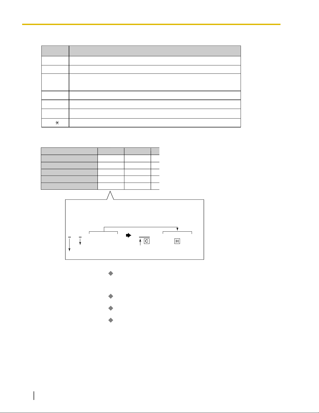
The following Absent Messages may be programmed:
System message 1
Personal
message
users can prepare a brief text message (Absent Message) that will be displayed to other extension
Type Message No. Message (Example) Description
Will Return Soon
2
3 At Ext %%%% (Extension
4 Back at %%:%% (Hour:Minute)
5 Out until %%/%% (Month/Day)
6
7
8
9 A message is programmable by
Gone Home
Number)
In a Meeting
Messages may be edited through
system programming. They can
be used by any extension user.
each extension through personal
programming (Personal Absent
Message), which can only be
used by that extension user.
Note
The "%" shown above indicates a parameter to be entered when assigning a message at an individual
extension.
Up to seven "%"s can be stored for each message.
Conditions
• An extension user can select only one Absent Message at a time. The selected message is displayed at
the extension while on-hook.
• The caller must use a display proprietary telephone (PT) to see the Absent Message.
PC Programming Manual References
4.8 [2-6-1] Numbering Plan
6.1 [4-1-1] Wired Extension—Extension Settings
6.10 [4-2-1] Portable Station—Extension Settings
8.5 [6-5] Absent Message
14 Feature Manual Document Version 2008-11
—Main—Features— Absent Message Set / Cancel
—Option 3—
—Option 3—
Absent Message
Absent Message
Page 15

1.1.2 Account Code Entry
PT Programming Manual References
[008] Absent Message
Feature Manual References
21.1 Capacity of System Resources
Operating Manual References
1.3.1 Absent Message
3.1.2 Personal Programming
1.1.2 Account Code Entry
Description
An account code is used to identify outgoing CO line calls for accounting and billing purposes. The account
code is appended to the Station Message Detail Recording (SMDR) call record. For example, a firm can use
an account code for each client to determine which calls were made for which client, and can submit a bill to
the client according to the client
There are two methods of entering account codes explained below.
One of the methods is selected for each extension based on Class of Service (COS) programming.
’s account code as shown on the SMDR call record.
Mode Description
Option An extension user can enter an account code, but is not required to.
Forced An extension user must always enter an account code before seizing a
CO line.
Conditions
• An account code can be stored in Memory Dialing (One-touch Dialing, for example).
• Account Button
A flexible button can be customized as the Account button. The Account button is used in place of the
feature number for entering an account code. This button is useful because it can be used at any time,
while feature number entry is allowed only when hearing a dial tone before seizing a CO line.
• Extension users can enter an account code at any time during a call, including after the call has been
disconnected
a reorder tone, the call will not be stored in the SMDR record.
• If an account code is entered more than once, the code entered last is logged in the SMDR.
• Even in Forced mode, emergency numbers can be dialed without an account code. (® 5.1.2 Emergency
Call)
• Proprietary telephone (PT) users can also enter an account code for incoming CO line calls during a
conversation.
• Verification Code Entry
To identify who made a CO line call for accounting and billing purposes, a verification code can be used.
This code can be used at any extension. (® 19.1.1 Verification Code Entry)
and a reorder tone is heard. However, if an account code is entered after there is no longer
Document Version 2008-11 Feature Manual 15
Page 16

1.1.3 ARS (Automatic Route Selection)
PC Programming Manual References
4.8 [2-6-1] Numbering Plan
4.11 [2-7-1] Class of Service—COS Settings—CO & SMDR— Account Code Mode
—Main—Features—
Account Code Entry
PT Programming Manual References
[508] Account Code Mode
Feature Manual References
3.1.19 COS (Class of Service)
6.1.3 Flexible Buttons
16.1.1 SMDR (Station Message Detail Recording)
Operating Manual References
1.2.1 Making Calls
1.1.3 ARS (Automatic Route Selection)
Description
Different
telephone carriers to make calls to different areas in an effort to reduce costs.
Automatic Route Selection (ARS) is a feature which automatically selects different carriers each time a CO
line call is made. In order to use ARS effectively, various ARS-related tables must be preprogrammed to tell
the PBX which calls should be placed using which carriers, during which time of day.
If you do not activate ARS, if ARS is bypassed, or if you do not use multiple carriers, CO line calls will be
connected via the carrier contracted for each line (default carrier).
telephone carriers charge different rates for calls placed to different areas. Your PBX may use different
16 Feature Manual Document Version 2008-11
Page 17
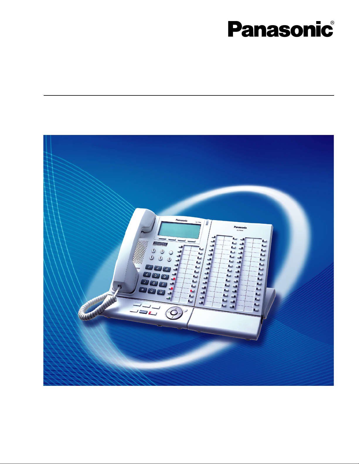
No
No (Normal CO Line Access)
No
No
Yes
Is the ARS mode (1) enabled?
An extension user accesses a CO
line and dials a telephone number.
Sends a
reorder tone.
Sends a
busy tone.
Checks the Routing Plan (4) to
determine which carrier to use.
Modifies the dialed number by
removing the digits and following
the modify commands (5).
Sends the modified number
to the CO line.
Yes
No
Is the carrier found in the
appropriate time block (4)?
Yes
Is the dialed number found in the
Leading Number Exception Table (2)?
No
Yes
(default)
Yes
Is normal
CO Line Access
allowed?
Because all CO
lines are busy?
Yes
Is the dialed number found in
the Leading Number Table (3)?
No
Is there an available
trunk group (5)?
Yes
Sends the telephone
number by the Idle
Line Access.
Sends the telephone
number as dialed.
1.1.3 ARS (Automatic Route Selection)
[Carrier Selection Procedure Flowchart]
The numbers in parentheses indicate the corresponding items found under [Programming Procedures] on the
following pages.
[Programming Procedures]
1. ARS Mode
ARS is turned on by selecting under which circumstances it operates
makes a call using the Idle Line Access method, or when any CO Line Access method is used (® 3.1.14 CO
Line Access). ARS can also be turned off for the entire system.
® 10.1 [8-1] System Setting—
® [320] ARS Mode
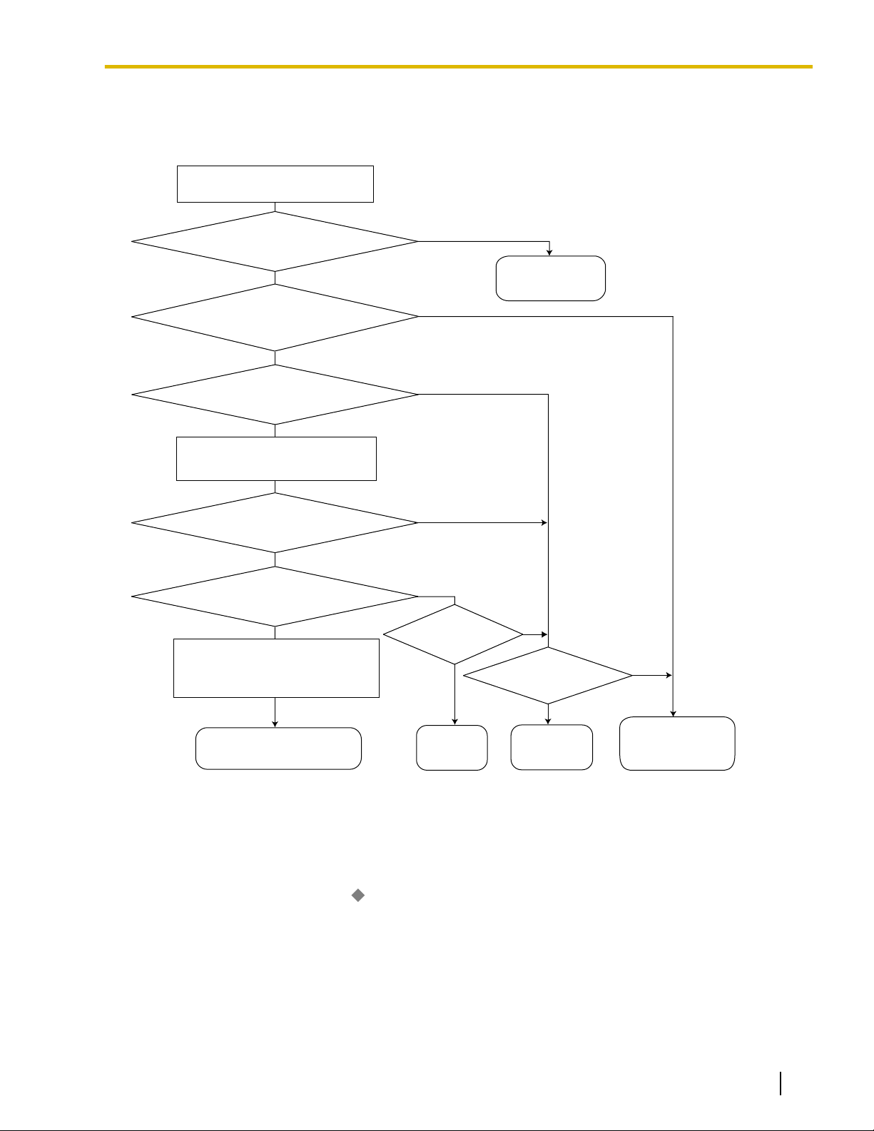
2. Leading Number Exception Table
Document Version 2008-11 Feature Manual 17
ARS is activated, store the telephone numbers that will bypass ARS in the Leading Number Exception
Once
Table.
Note that the first few digits (leading number) of a telephone number, such as an area code or local
exchange, can also be stored, so that all calls to those areas or exchanges are exempted from ARS. Also
ARS Mode
– either when an extension user
Page 18
Location
No.
1
2
3
Leading No.
Exception
*1
555
556
567
Location
No.
1
2
3
Leading
No.
*1
1212
01181
01144
Routing Plan
No.
*3
1
5
12
Additional
No. of Digits
*2
7
0
0
1.1.3 ARS (Automatic Route Selection)
note that the CO Line Access number is always ignored by ARS and does not need to be programmed
here.
Calls
that are exempt from ARS are connected to the user-selected line, via the default carrier for that line.
[Programming Example: ARS Leading Number Exception Table]
*1
® 10.7 [8-6] Leading Number Exception
® [325] ARS Exception Number
In this example:
555, 556, and 567 are local exchanges. (555-XXXX, 556-XXXX, 567-XXXX)
These calls can be made using any carrier, and are therefore exempt from ARS.
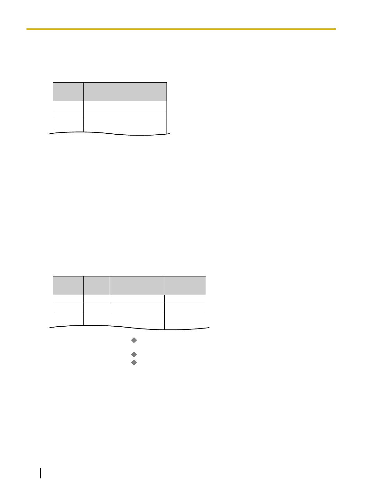
3. Leading Number Table
Next,
store the leading numbers of telephone numbers that should be routed by ARS, and assign a Routing
Plan to each leading number that will control how calls containing these leading numbers are routed.
When an extension user dials a number which contains a leading number stored in the ARS Leading
Number Table, the call will be routed the corresponding Routing Plan assigned here. Note that the CO
Line Access number is always ignored by ARS and does not need to be programmed here.
Before programming the details of each Routing Plan (explained below), you can simply assign here the
same Routing Plan number to all the different leading numbers which will be routed the same way.
If a dialed number matches two or more leading numbers stored in the ARS Leading Number Table, the
lowest numbered location will have priority.
18 Feature Manual Document Version 2008-11
[Programming Example: ARS Leading Number Table]
*1
® 10.2 [8-2] Leading Number
® [321] ARS Leading Number
*2
® 10.2 [8-2] Leading Number
*3
® 10.2 [8-2] Leading Number
® [322] ARS Routing Plan Table Number
Leading Number
—
Additional Number of Digits
—
Routing Plan Number
—
Additional Number of Digits
In
order for calls to be made using the desired carrier, telephone numbers dialed by extension users must
be modified to meet the criteria required by the carrier. (Refer to 5. Carrier Table.) This modification usually
involves removing digits and adding access codes to the beginning of the dialed number.
In situations where a preprogrammed number (such as an Itemized Billing Code) must be added
automatically after the telephone number that was dialed by the extension user, set the Additional Number
of Digits to a value greater than 0.
4. Routing Plan
Page 19
ARS Leading Number Table
ARS Routing Plan No. 1
1
2
3
Location
No.
1212
01181
01144
Leading
No.
7
0
0
1
5
12
Additional No.
of Digits
Routing Plan
No.
Monday
Time Table
*1
Carrier
*2
Time Block A
Time Block B
Time Block C
Time Block D
Priority 1
Carrier A
Carrier A
Carrier C
Carrier J
Priority 2
Carrier M
Carrier M
Carrier M
Carrier M
9:00
12:00
17:00
23:00
1.1.3 ARS (Automatic Route Selection)
Since the preferred carrier may vary depending on the time of day, you can create an ARS-specific time
table and break each day of the week into different time blocks. A different carrier can then be assigned
to each time block.
Routing
Plan Time Table: For each Routing Plan, a different carrier can be assigned for each time of day
and each day of the week. Each day can have up to four programmable time blocks.
Routing Plan Priority: For each Routing Plan, a different carrier can be assigned a different priority for
each time of day. Generally, the carrier assigned to priority 1 will be used, however, if the CO lines assigned
to this carrier are busy, a different available carrier will be used according to priority level.
*1
® 10.4 [8-3] Routing Plan Time—Time Setting
® [330] ARS Routing Plan Time Table
*2
® 10.5 [8-4] Routing Plan Priority
® [331–346] ARS Routing Plan Table (1
® [347] ARS Routing Plan Table (1–48) (KX-TDA600 only)
5. Carrier Table
Each carrier must be programmed in the Carrier Table. Here each carrier is assigned a carrier number,
name, the CO lines it is used with, etc.
® 10.6 [8-5] Carrier—Carrier
Carrier Name: Assign a name for the carrier. Used only as a reference.
Trunk Group: Assign the trunk groups which can be used when making calls via this carrier.
Carrier Access Code: Enter the carrier’s access code. Consult carrier for details.
Removed Number of Digits: There may be circumstances where the user-dialed number must be
modified in order for the carrier to connect the call. In this case, enter here the number of digits to be
removed automatically from the beginning of the dialed number.
Modify Command: When a call is made using this carrier, the telephone number must be modified to meet
the criteria required by the carrier in order to connect the call. Program here the commands needed to
modify the user-dialed number as necessary.
–16) (KX-TDA50/KX-TDA100/KX-TDA200 only)
Document Version 2008-11 Feature Manual 19
Page 20
Command
Description
Inserts the Carrier Access Code
Inserts the user-dialed number minus any removed digits
Analog Line: Inserts a pause
ISDN/T1 Line: Inserts a pause and changes dialing mode to tone (DTMF)
Inserts the Authorization Code for Tenant
Inserts the Authorization Code for Trunk Group
Inserts the Itemized Billing Code
You can enter any of these digits in a modify command
C
H
P
A
G
I
[0-9, , #]
In this example
Dialed number: 9-1-212-555-5555
Modification:
9 1 2125555555 0880 2125555555
Remove 1 digit Add the Carrier Access Code
CO Line Access no. is ignored
Carrier A
1, 2, 3
0880
1
CH
Carrier Name
*1
Trunk Group
*2
Carrier Access Code
*3
Removed No. of Digits
*4
Modify Command
*5
Carrier J
4
0700
3
CPH
Carrier 1 Carrier 2
1.1.3 ARS (Automatic Route Selection)
[Command Explanation]
[Programming Example: Carrier Table]
*1
® 10.6 [8-5] Carrier—Carrier— Carrier Name
® [350] ARS Carrier Name
*2
® 10.6 [8-5] Carrier—TRG 01–TRG 64 (KX-TDA50/KX-TDA100/KX-TDA200
® [351] ARS Trunk Group for Carrier Access
*3
® 10.6 [8-5] Carrier—Carrier—
® [353] ARS Carrier Access Code
*4
6. ARS Options
® 10.6 [8-5] Carrier—Carrier—
® [352] ARS Removed Number of Digits for Carrier Access
*5
® 10.6 [8-5] Carrier—Carrier—
Authorization Code for a Tenant
A Carrier Authorization Code can be assigned to each tenant.
10.6 [8-5] Carrier—Authorization Code for Tenant
Authorization Code for Trunk Group
A Carrier Authorization Code can be assigned to each trunk group.
20 Feature Manual Document Version 2008-11
), or TRG 01–TRG 96 (KX-TDA600)
Carrier Access Code
Removed Number of Digits
Modify Command
Page 21

10.8 [8-7] Authorization Code for TRG
Itemized Billing Code
An Itemized Billing Code can be assigned for each extension and for each verification code.
If a call is not made from an extension, such as via Direct Inward System Access (DISA) or TIE line, and
no
verification code is used, the Itemized Billing Code assigned to location 1 in the Verification Code Table
will be used.
6.1 [4-1-1] Wired Extension—Extension Settings—Option 1—
6.10 [4-2-1] Portable Station—Extension Settings
8.3 [6-3] Verification Code— Itemized Billing Code for ARS
Conditions
CAUTION
The software contained in the ARS feature to allow user access to the network must be upgraded to
recognize newly established network area codes and exchange codes as they are placed into service.
Failure to upgrade the premises PBXs or peripheral equipment to recognize the new codes as they are
established will restrict the customer and the customer
and to these codes.
KEEP THE SOFTWARE UP-TO-DATE WITH THE LATEST DATA.
• Logging Outgoing Calls by SMDR
Whether SMDR logs the user-dialed number or the ARS-modified number is determined through system
programming.
1.1.3 ARS (Automatic Route Selection)
ARS Itemized Code
—Option 1—
’s employees from gaining access to the network
ARS Itemized Code
• ARS Data Import/Export
ARS tables and data can be copied to and from the PBX and a PC using the Maintenance Console software.
Files are saved in CSV (Comma Separated Value) format. Because of the large amounts of programming
that may be necessary to use ARS effectively, you may choose to export ARS tables and data to a PC,
edit them using the software of your choosing, then import the new data to the PBX. This is particularly
convenient if you need to update your ARS tables for new area codes or telephone rates, or when you’d
like to copy ARS tables from one PBX to another.
2.5.8 Tool—Import
2.5.9 Tool—Export
• TRS
Toll Restriction (TRS) checks are performed before ARS number modification, so program TRS Denied
Code Tables and Exception Code Tables accordingly. (® 17.1.6 TRS (Toll Restriction))
• When ARS Routing Takes Place
ARS routing takes place after the preprogrammed number of digits (leading number + additional number
of digits) have been dialed.
PC Programming Manual References
2.5.8 Tool—Import
→ARS - Leading Digit
→ARS - Except Code
→ARS - Routing Plan
2.5.9 Tool—Export
4.4 [2-3] Timers & Counters—Dial / IRNA / Recall / Tone—
4.17 [2-9] System Options—Option 3— Dial Tone—Dial Tone for ARS
6.1 [4-1-1] Wired Extension—Extension Settings
6.10 [4-2-1] Portable Station—Extension Settings
8.3 [6-3] Verification Code— Itemized Billing Code for ARS
—Option 2—
—Option 2—
Dial—Extension Inter-digit
ARS Itemized Code
ARS Itemized Code
Document Version 2008-11 Feature Manual 21
Page 22

1.1.4 Automatic Callback Busy (Camp-on)
Section 10 [8] ARS
13.1 [11-1] Main—SMDR— SMDR Options—ARS Dial
PT Programming Manual References
[320] ARS Mode
[321] ARS Leading Number
[322] ARS Routing Plan Table Number
[325] ARS Exception Number
[330] ARS Routing Plan Time Table
[331–346] ARS Routing Plan Table (1–16) (KX-TDA50/KX-TDA100/KX-TDA200 only)
[347] ARS Routing Plan Table (1–48) (KX-TDA600 only)
[350] ARS Carrier Name
[351] ARS Trunk Group for Carrier Access
[352] ARS Removed Number of Digits for Carrier Access
[353] ARS Carrier Access Code
[325] ARS Exception Number
Feature Manual References
21.1 Capacity of System Resources
1.1.4 Automatic Callback Busy (Camp-on)
Description
If the line is busy when a call is made, a callback ring can inform the caller when the line becomes free.
If the called party was another extension, or if the dialed number is handled by Automatic Route Selection
(ARS), the number is automatically redialed after the extension user answers the callback ring.
Conditions
• If the callback ring is not answered within 10 seconds, callback is cancelled.
• If the extension hears a busy tone before dialing the telephone number, only the CO line or trunk group is
reserved. After answering the callback ring, the extension should dial the telephone number.
• An extension can set only one Automatic Callback Busy. The last setting is effective.
• Multiple extension users can set this feature for the same CO line at the same time.
However, a maximum of four extension users can set this feature to one extension.
Callback ringing will be sent to extensions in the order that the feature was set. In other words, the extension
that set the feature first will receive a callback ringing first.
• This feature cannot be used for calls to a Voice Processing System (VPS).
PC Programming Manual References
4.8 [2-6-1] Numbering Plan—Main—Features—
4.10 [2-6-3] Numbering Plan
—B/NA DND Call Feature—
Automatic Callback Busy Cancel
Automatic Callback Busy
Operating Manual References
1.3.4 Automatic Callback Busy (Camp-on)
22 Feature Manual Document Version 2008-11
Page 23

1.1.6 Automatic Fax Transfer
1.1.5 Automatic Extension Release
Description
After going off-hook, if an extension user fails to dial any digits within a preprogrammed time period, the user
will hear a reorder tone. This operation applies to intercom calls only.
This feature is also known as Automatic Station Release.
Conditions
• A proprietary telephone (PT)/portable station (PS) user hears a reorder tone for a preprogrammed time
period,
a reorder tone until he or she goes on-hook.
• This feature works in one of the following cases:
When making an intercom call
a. The first digit is not dialed within a preprogrammed time period.
b. A digit is dialed, but subsequent digits are not dialed within a preprogrammed time period.
PC Programming Manual References
and then the PT/PS returns to idle status automatically. A single line telephone (SLT) user will hear
4.4 [2-3] Timers & Counters—Dial / IRNA / Recall / Tone
Dial—Extension First Digit
→
→ Dial—Extension Inter-digit
→ Tone Length—Reorder Tone for PT Handset
→ Tone Length—Reorder Tone for PT Hands-free
1.1.6 Automatic Fax Transfer
Description
The PBX can distinguish between fax calls and other types of calls arriving on DISA lines, and automatically
transfer fax calls to preprogrammed destinations. When a call arrives on a DISA line, an OGM is played (®
12.1.2 OGM (Outgoing Message)). At the same time, the PBX begins fax signal detection. If a fax signal is
detected, the PBX recognizes that the call is a fax call, and transfers the call to the fax destination assigned
to
that OGM through system programming. This allows a single CO line to be used seamlessly for both voice
and fax calls, with only voice calls arriving at user extensions.
This feature is only available for the KX-TDA50.
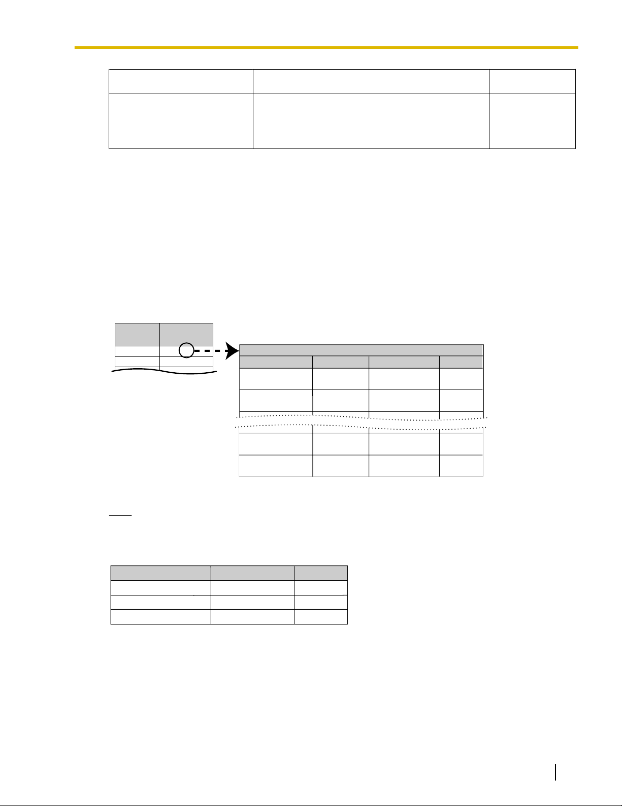
[Available Automatic Fax Transfer Destinations]
Destination Availability
Wired Extension (PT/SLT/T1-OPX)
PS
ü
*1
ü
ICD Group
PS Ring Group
Floating Extension no. for SVM
VM Group (DTMF/DPT)
External Pager (TAFAS)
Document Version 2008-11 Feature Manual 23
ü
Page 24

1.1.7 Automatic Time Adjustment
Destination Availability
DISA
Analog/ISDN Remote Maintenance
Idle Line Access no. + Phone no.
Trunk Group Access no. + Trunk Group no. + Phone no.
Extension of Another PBX (via TIE Line, Access with PBX Code)
Extension of Another PBX (via TIE Line, Access without PBX Code)
*1
A
PS destination can be used to forward fax calls to a fax machine at another PBX connected by TIE line. A virtual PS can be specified
as the destination of fax calls. Then, the extension number of the fax machine at the other PBX can be specified as the FWD—ALL
Calls destination for calls to that virtual PS. (® 19.1.2 Virtual PS)
Conditions
• Hardware Requirement: An MSG2 card or ESVM2 card
• This feature is only effective for calls arriving on DISA lines.
• If a fax signal is not detected before the DISA Intercept Routing—No Dial timer expires, the call is redirected
to the operator extension, and fax detection ends.
Installation Manual References
2.5.3 MSG2 Card (KX-TDA5191)
2.5.5 ESVM2 Card (KX-TDA5194)
PC Programming Manual References
7.4 [5-3-2] Voice Message—DISA Message—
Fax Extension (KX-TDA50 only)
Feature Manual References
4.1.7 DISA (Direct Inward System Access)
21.2 Exclusive Features Table
1.1.7 Automatic Time Adjustment
Description
The PBX clock can be adjusted automatically in the following two ways:
1. Daylight Saving Time Setting
The start and end dates of Daylight Saving Time can be programmed. The PBX clock will automatically
adjust
itself one hour forward or backward at 2:00 A.M. on the programmed date, if enabled through system
programming. At 2:00 A.M. on the start date, the clock will change to 3:00 A.M., and at 2:00 A.M. on the
end date, the clock will change to 1:00 A.M.
Note
If a Timed Reminder (Remote Wake-up call) is set:
– On the Daylight Saving Time start date, a reminder set for between 2:00 A.M. and 3:00 A.M. will
not ring.
24 Feature Manual Document Version 2008-11
Page 25

1.1.7 Automatic Time Adjustment
– On the Daylight Saving Time end date, a reminder set for between 1:00 A.M. and 2:00 A.M. will
ring twice.
2. Time Information from Telephone Company
Time information can be received when
– An incoming or outgoing call through an ISDN line is received/made.
– An incoming call through an analog line with Caller ID which includes time information is received.
The PBX clock will be adjusted everyday with the first call after 3:05 AM, if enabled through system
programming.
Note
If
a Timed Reminder (Remote Wake-up call) is set, the setting will not ring or will ring twice depending
on the adjustment.
Conditions
• Station Message Detail Recording (SMDR) will log call information using the PBX clock so that the logging
time will be overlapped at the end of Daylight Saving Time. (® 16.1.1 SMDR (Station Message Detail
Recording))
PC Programming Manual References
4.1 [2-1] Date & Time/Daylight Saving
4.17 [2-9] System Options—Option 2—
Automatic Time Adjustment—by ISDN & Caller ID (FSK)
Feature Manual References
9.1.16 ISDN (INTEGRATED SERVICES DIGITAL NETWORK) FEATURES
17.1.4 Timed Reminder
Document Version 2008-11 Feature Manual 25
Page 26

1.1.7 Automatic Time Adjustment
26 Feature Manual Document Version 2008-11
Page 27

Section 2
Features and Configurations—B
Document Version 2008-11 Feature Manual 27
Page 28

2.1.1 BGM (Background Music)
2.1 B
2.1.1 BGM (Background Music)
Description
A proprietary telephone (PT) user can listen to background music (BGM) through the built-in speaker while
on-hook and idle.
BGM—External:
BGM
can also be broadcast in the office through external pagers (loudspeakers) and can be turned on and off
by an extension assigned as a manager.
Conditions
[BGM]
• Hardware requirement: A user-supplied external audio source, such as a CD player or radio.
• The music heard through the PT is interrupted when going off-hook.
• KX-TDA100/KX-TDA200/KX-TDA600 only
Each extension user can select the audio source.
• KX-TDA50 only
Each user can only set/cancel BGM; the user cannot make a music selection.
[BGM—External]
• Hardware requirement: A user-supplied external pager
• External pagers can be used with the following priorities:
Trunk Answer From Any Station (TAFAS) ® Paging ® BGM
(® 13.1.1 Paging, ® 17.1.2 TAFAS (Trunk Answer From Any Station))
Installation Manual References
KX-TDA50
2.10.1 Connection of Peripherals
KX-TDA100/KX-TDA200
2.10.1 Connection of Peripherals
KX-TDA600
2.13.1 Connection of Peripherals
PC Programming Manual References
4.3 [2-2] Operator & BGM
BGM and Music on Hold—Music Source of BGM2 (KX-TDA100/KX-TDA200/KX-TDA600 only)
→
→ BGM and Music on Hold—Music Source of BGM (KX-TDA50 only)
4.8 [2-6-1] Numbering Plan
External BGM On / Off
→
→ BGM Set / Cancel
4.19 [2-11-1] Audio Gain—Paging/MOH
MOH—MOH 1 (Music On Hold 1) (KX-TDA100/KX-TDA200/KX-TDA600 only)
→
→ MOH—MOH 2 (Music On Hold 2) (KX-TDA100/KX-TDA200/KX-TDA600 only)
—Main—Features
28 Feature Manual Document Version 2008-11
Page 29

→ MOH—MOH (Music On Hold) (KX-TDA50 only)
7.2 [5-2] External Pager
Operating Manual References
1.3.5 BGM (Background Music)
2.1.2 External BGM (Background Music)
2.1.1 BGM (Background Music)
Document Version 2008-11 Feature Manual 29
Page 30

2.1.1 BGM (Background Music)
30 Feature Manual Document Version 2008-11
Page 31

Section 3
Features and Configurations—C
Document Version 2008-11 Feature Manual 31
Page 32

3.1.1 Caller ID
3.1 C
3.1.1 Caller ID
Description
The
PBX can receive Caller ID information (a caller’s name and telephone number) from calls received on CO
lines. This information can be shown on a proprietary telephone (PT) display when receiving a call and can be
used to direct calls from specific callers to specific destinations automatically. Additionally, Caller ID information
is logged in the Incoming Call Log of the extension which received the call, allowing the caller to view a record
of incoming calls or make a call to a person in the call log later.
The PBX can be programmed to modify a caller’s telephone number when it is received and, for example, add
a CO Line Access number or add/delete certain digits of incoming telephone numbers automatically. This
allows an extension user to be able to make a call later to a telephone number logged in his or her call log
without worrying about CO Line Access numbers, area codes, etc.
Note
• The
• To receive Caller ID information, you must subscribe to the telephone company’s Caller ID service and
Caller ID to SLT Port:
Caller ID information can also be shown on a single line telephone (SLT) display. This feature is available only
for SLTs compatible with FSK-type Caller ID.
term "Caller ID" used in this Feature Manual refers to features that can receive caller information
sent from the telephone company and received on analog, ISDN, and T1 lines. Your network provider
may use a different name for this type of service.
enable Caller ID for the appropriate CO line through system programming.
1. Caller ID Features
There are three features which can receive Caller ID information. The available feature depends on the
type of CO line receiving the call.
Feature Description Details in
Caller ID Receives caller information sent from the telephone
company over analog CO lines.
Calling Line Identification
Presentation (CLIP)
Automatic Number
Identification (ANI)
(KX-TDA100/KX-TDA200
KX-TDA600)
Receives caller information sent from the telephone
company over ISDN lines.
Receives caller information sent from the telephone
company over T1 lines.
/
–
–
®
17.1.1 T1 Line
Service
2. Caller ID-Related Features
Feature Description Details in
Calling Line Identification
(CLI) Distribution
Caller ID information received by the PBX is used to
direct calls from specific callers to specific
destinations. The caller
destination must be assigned in the System Speed
Dialing Table.
’s telephone number and a
® 3.1.12 CLI
(Calling Line
Identification)
Distribution
32 Feature Manual Document Version 2008-11
Page 33
<Modification Table>
[Not
programmable
]
0
0
Local/International
Call Data 10
Long Distance
Code Data
212
Local/International
Call Data 1
Local/International
Call Data 2
Area Code
Removed No. of Digits
Added No.
Modification Table 1
011
3
3
001
0
<Table Selection>
Trunk
Group No.
1
2
Modification
Table
1
3
International Call Data
National Call Data
Subscriber Call Data
Removed No. of Digits
Added No.
<Modification Table>
0
0
0
011
1
3.1.1 Caller ID
Feature Description Details in
Incoming Call Log Caller information is automatically recorded in the
call
log of the extension which received the call. This
® 3.1.3
Incoming
Call Log,
information can be used to view a record of incoming
calls or make calls to any number in the call log.
3. Automatic Caller ID Number Modification
When a call is received, the PBX can automatically modify the caller
preprogrammed set of rules (Caller ID Modification Table). This modified number will be automatically
stored in the extension’s Incoming Call Log, allowing the extension user to make a call to this number later
without worrying about CO Line Access numbers, area codes, etc.
Each trunk group can be assigned a modification table. Each table has ten formulas for modifying local/
international numbers, and one formula for modifying long distance numbers. When a call is received, the
PBX compares the received telephone number to the area codes programmed under "Local/International
Call Data" first. If a match is not found, the telephone number will be modified according to the method
programmed under "Long Distance Code".
’s telephone number according to a
[Programming Example: Caller ID Modification]
Document Version 2008-11 Feature Manual 33
Note
When Caller ID information is received from a call on an ISDN line and the call type is International,
National, or Subscriber, the following modification table is used instead of the above table:
Data entered under "Removed No. of Digits" and "Added No." for International, National, and Subscriber
call data will be applied respectively to international, long distance, and local calls.
Page 34

A CO line call containing
Caller ID information is received.
Yes No
Is the caller's area code stored in
the Caller ID Modification Table?
Modifies the number according to the
method programmed in the corresponding
"Local/International Call Data" field.
Example:
Removed number of digits: 3
Added number: 9
Example:
Received number:
Modified number:
212 555 1234
9 555 1234
Modification is complete.
Modified number is logged.
Modification is complete.
Modified number is logged.
Checks the Caller ID Modification Table assigned to the Trunk Group.
Modifies the number according to the
method programmed in the "Long Distance
Code" field.
Example:
Removed number of digits: 0
Added number: 91
Example:
Received number:
Modified number:
313 555 1234
91 313 555 1234
3.1.1 Caller ID
<Modification Flowchart>
4. System Speed Dialing Table
The
System Speed Dialing Table can store telephone numbers, names, and CLI destinations for hundreds
of callers.
a. Telephone Number: Contains a CO Line Access number and the caller’s telephone number. If
Automatic Caller ID Number Modification is used, telephone numbers should be stored in the System
Speed Dialing Table in their modified format in order for CLI distribution to function.
b. Caller’s Name: Shown on the display and logged (Incoming Call Log, Station Message Detail
Recording [SMDR]) when a call from this telephone number is received.
c. CLI Destination: The destination to which an incoming call from the stored telephone number is
directed via the CLI distribution feature.
34 Feature Manual Document Version 2008-11
Page 35

Location
(System Speed
Dialing No.)
000
001
System Speed
Dialing Name
*1
ABC Company
XYZ Company
Telephone No.
*2
912125551234
913135551234
CLI Destination
*3
200
300
3.1.1 Caller ID
[Programming Example: System Speed Dialing Table]
*1
® 8.1 [6-1] System Speed Dial— CO Line Access Number + Telephone Number
® [001] System Speed Dialing Number
*2
® 8.1 [6-1] System Speed Dial—
® [002] System Speed Dialing Name
*3
® 8.1 [6-1] System Speed Dial—
Name
CLI Destination
5. Displaying the Caller’s Name
In
addition to the System Speed Dialing Table, each extension can store names and numbers in Personal
Speed Dialing. Therefore, it is entirely possible for the same telephone number to be stored under a
different name in different locations within the PBX.
When a call containing Caller ID information is received, the PBX will search for the caller’s name in the
following order, then show that name on the display and log it via SMDR.
1. Personal Speed Dialing data of the extension which received the call
2. System Speed Dialing Table
3. The Caller ID information received from the telephone company
If a caller’s name is not stored in the PBX or sent from the telephone company, it will not be displayed or
logged.
Conditions
[General]
• Caller ID signaling type can be selected through system programming.
[Caller ID to SLT Port]
• Hardware Requirement:
KX-TDA50: The EXT-CID card
KX-TDA100/KX-TDA200: An SLC8 card with an EXT-CID card installed, or a CSLC16 card
KX-TDA600: An SLC8 card with an EXT-CID card installed, a CSLC16 card, or an ECSLC24 card
• When the caller’s number is sent to an SLT, a CO Line Access number can be automatically added to the
telephone number through system programming for calling back.
• KX-TDA50 only
Through system programming, a group of 4 SLT or Super Hybrid ports can be assigned to receive Caller
ID information. Up to 2 groups can be programmed. Therefore, a maximum of 8 SLTs can receive Caller
ID information.
Note that SLTs connected in parallel to DPTs attached to Super Hybrid ports can only receive Caller ID
information when set to "ring" mode.
• When the caller’s number exceeds 16 digits, the SLT receives only the first 16 digits, not counting the
preceding CO Line Access number (if it is programmed to be added).
• If a call is transferred to an SLT, the transferring extension’s information will be shown on the SLT. If the
transferring extension goes on-hook before the call is answered, the original caller’s information will be
shown.
• When Caller ID information such as "Private", "Out of Area", or "Long Distance" is received, this information
will be shown instead of the caller’s number and name.
Document Version 2008-11 Feature Manual 35
Page 36

3.1.2 Call Hold
• Even if the caller’s name is sent, the name may not be shown depending on the type of SLT.
• Incoming Call Log information is not shown on the SLT
• Caller ID shows whether the call is an intercom or CO line call by default. This setting can be disabled
through system programming.
• A caller ID name received from the network via a PRI23 card will not be displayed on an SLT. However, if
the received caller ID matches a System Speed Dialing entry, and a name is registered for that entry, it
will be displayed.
PC Programming Manual References
4.4 [2-3] Timers & Counters—Miscellaneous
Caller ID—Waiting to receive
→
→ Caller ID—Visual Caller ID Display
4.17 [2-9] System Options—Option 4— Private Network—Public Call through Private Network—Minimum
Public Caller ID Digits
4.18 [2-10] Extension CID Settings
5.1 [3-1-1] Trunk Group—TRG Settings—Main—
6.1 [4-1-1] Wired Extension—Extension Settings—Option 8
Extension Caller ID
→
→ Incoming Call Wait Timer for Extension Caller ID
8.1 [6-1] System Speed Dial
5.3 [3-1-3] Caller ID Modification
Caller ID Modification Table
PT Programming Manual References
[001] System Speed Dialing Number
[002] System Speed Dialing Name
[490] Caller ID Signal Type
Feature Manual References
16.1.1 SMDR (Station Message Detail Recording)
16.1.3 Speed Dialing, Personal
16.1.4 Speed Dialing, System
3.1.2 Call Hold
Description
An extension user can put a call on hold. The following Hold features are available:
Feature Description
Regular Hold Any extension can retrieve a held call.
Exclusive Call Hold Only the extension user who held the call can retrieve it.
The result of the holding operation can be determined through system programming. Pressing the HOLD button
again just after the first time alternates the mode between Regular and Exclusive Call Hold.
36 Feature Manual Document Version 2008-11
Page 37

3.1.2 Call Hold
Conditions
• Call Hold Limitation
A proprietary telephone (PT) user can hold one intercom call and/or multiple CO line calls at a time. A
single line telephone (SLT) user can hold either one intercom call or one CO line call at a time. By using
the
Call Park feature, PT and SLT users can hold multiple CO line calls and intercom calls simultaneously.
(® 3.1.5 Call Park)
• Music on Hold
Music, if available, is sent to the held party. (® 11.1.4 Music on Hold)
• Hold Recall
If a call on hold is not retrieved within a preprogrammed time period, the Hold Recall tone is heard at the
extension which put the call on hold. If the extension is engaged in a call, the Hold Alarm will be heard.
• If an outside party is placed on hold and the call is not retrieved within a preprogrammed time period after
the Hold Recall time expires, the call is automatically disconnected.
• Automatic Call Hold
A PT can be configured through system programming to place the current call on hold when the PT user
presses a CO, ICD Group, INTERCOM or PDN button to make or answer another call. If this feature is not
enabled, the current call will be disconnected.
[Example of Automatic Call Hold]
It is possible to receive an incoming CO line call by pressing the flashing ICD Group button. The current
intercom call (on the INTERCOM button) is placed on hold. To return to the held call, press the INTERCOM
button.
• Call Hold Retrieve Deny
Internal Call Block (® 9.1.14 Internal Call Block) also determines which extensions’ calls an extension
user can retrieve, i.e., if extension 101 cannot call extension 201, then it cannot retrieve extension 201’s
held calls either.
• SLT Hold Mode
It is possible to choose how to hold and transfer a call with an SLT through system programming. The
following methods are available:
Mode 1
Mode 2
(Default)
Mode 3
Hold
Flashing the
hookswitch
+
Going on-hook
Flashing the
hookswitch
+
Hold Feature No.
+
Going on-hook
Flashing the
hookswitch
+
Hold Feature No.
+
Going on-hook
Hold
(to be Retrieved from
Another Extension)
Flashing the hookswitch
+
Hold Feature No.
+
Going on-hook
Flashing the hookswitch
+
Hold Feature No.
+
Going on-hook
Flashing the hookswitch
+
Hold Feature No.
+
Hold Feature No.
+
Going on-hook
*1
Transfer to CO
Line
Flashing the
hookswitch
+
CO Line Access No.
Flashing the
hookswitch
+
CO Line Access No.
Flashing the
hookswitch
+
Hold Feature No.
+
CO Line Access No.
Transfer to
Extension
Flashing the
hookswitch
+
Extension No.
Flashing the
hookswitch
+
Extension No.
Flashing the
hookswitch
+
Extension No.
Document Version 2008-11 Feature Manual 37
Page 38

3.1.3 Call Log, Incoming
Hold
Hold
Flashing the
hookswitch
+
Mode 4
*1
These operations must be performed when the held call is intended to be retrieved from another extension using the holding
extension number.
If one of the following occurs frequently with an SLT, choose "Mode 2", "Mode 3", or "Mode 4":
Hold Feature No.
+
Going on-hook
(to be Retrieved from
Another Extension)
Flashing the hookswitch
+
Hold Feature No.
+
Hold Feature No.
+
Going on-hook
*1
a. When an SLT user answers a call, a reorder tone is heard or no one is heard on the other end.
b. When an SLT user goes off-hook, a reorder tone is heard instead of a dial tone.
If a call is not terminated after going on-hook, the above cases occur. To avoid these problems,
choose "Mode 2", "Mode 3", or "Mode 4". Every call will be terminated unless the Hold feature number
is entered after flashing the hookswitch in
Mode 2, Mode 3, and Mode 4.
• Hold Alarm tone pattern has a default. (® 21.3 Tones/Ring Tones)
PC Programming Manual References
Transfer to CO
Line
Flashing the
hookswitch
+
Hold Feature No.
+
CO Line Access No.
Transfer to
Extension
Flashing the
hookswitch
+
Hold Feature No.
+
Extension No.
4.4 [2-3] Timers & Counters—Dial / IRNA / Recall / Tone
Recall—Hold Recall
→
→ Recall—Disconnect after Recall
4.8 [2-6-1] Numbering Plan
Call Hold / Call Hold Retrieve
→
→ Call Hold Retrieve : Specified with a Holding Extension Number
→ Hold Retrieve : Specified with a Held CO Line Number
4.17 [2-9] System Options
→Option 1—
→Option 1— PT Operation—Hold Key Mode
→Option 5— SLT—SLT Hold Mode
PT Operation—Automatic Hold by ICM / CO / ICD Group key
—Main—Features
PT Programming Manual References
[200] Hold Recall Time
Operating Manual References
1.3.6 Call Hold
3.1.3 Call Log, Incoming
Description
When a call containing Caller ID information is received by an extension, the information is shown on the
telephone display, notifying the extension user of the caller
logged in the Incoming Call Log of the extension, and can be viewed later or used to call that caller back.
38 Feature Manual Document Version 2008-11
’s identity. This information is also automatically
Page 39

This extension
Incoming call distribution group
Call Log buttons
John White
DEC.12 10:00AM MON
NEW: Not Answered
123456789
--- Caller's name (20 digits max.)
--- Date and time of a call received
--- Answering Status*
--- Caller's number (16 digits max.)
"NEW" is displayed for call records which have not previously been viewed;
"OLD" is displayed for call records which have previously been viewed.
*:
3.1.3 Call Log, Incoming
Each extension and incoming call distribution (ICD) group has its own Incoming Call Log.
Call Log Button
The Call Log button will alert an extension user to any missed (unanswered) calls. A flexible button can be
customized as the Call Log button, and will indicate the status of the Incoming Call Log for the extension or
corresponding ICD group, as shown below.
Light pattern Status of the corresponding call log
Red on There are call records in the log which have not been viewed.
Off There are no new call records in the log.
Document Version 2008-11 Feature Manual 39
Page 40

KX-T7636/KX-T7633/
KX-T7630/KX-T7433
KX-NT300 series (except
KX-NT321)/KX-DT300 series
(except KX-DT321)/KX-NT136
Telephone
Caller's Name
Information
Caller's Phone
Number
Date/Time call
received
Answered or
Not Answered
Confirmed or
Not Confirmed
KX-TD7695/KX-TD7685/
KX-TD7694/KX-TD7684/
KX-TD7690/KX-TD7680
6-line display PT
3-line display PT except
KX-T7633/KX-T7630/
KX-T7433
1-line or 2-line display PT
KX-NT321/KX-NT265/
KX-DT321
Wireless phone
(KX-TD7895/KX-T7885)
*
*
Wireless phone
(KX-TD7896)
3.1.3 Call Log, Incoming
Conditions
• The following information is logged.
• If the answering destination is not the original extension (e.g., Call Pickup or FWD—No Answer), the call
• Incoming Call Log for Calls to a PS
• Display Lock
• Incoming Call Log Memory
• Automatic Caller ID Number Modification
40 Feature Manual Document Version 2008-11
*1
If the caller’s name is not logged, the caller
If the caller’s name is logged, the caller’s phone number is not displayed.
’s phone number is displayed.
is logged in the Incoming Call Logs of both the original and the answering destination. If a call is forwarded
to multiple extensions before being answered, the call is logged in the call logs of all the extensions it was
forwarded to. If a call is forwarded to an ICD group and is not answered, the call is not logged in the call
log for the ICD group.
Each portable station (PS) also has an Incoming Call Log. When a call is directed to a PS, the call will be
logged in the call log of the PS even when:
a. The PS is out of range.
b. The PS is turned off.
c. The Cell Station (CS) is busy.
The Incoming Call Log of an extension can be locked through personal programming (Directory and Call
Log Lock) to prevent other users from viewing its contents. In this case, the Outgoing Call Log display, the
Personal Speed Dialing number display and the SVM Log display are also locked, and the voice messages
in the user’s message box cannot be played back.
An extension personal identification number (PIN) is required to use this feature. (® 5.1.6 Extension PIN
(Personal Identification Number))
The total number of incoming calls that can be logged by the PBX is limited. The maximum number of calls
that can be logged in the Incoming Call Log of each extension and ICD group can be specified through
system programming. When a call log is full, the oldest call will be replaced each time a call is received.
Page 41

If the PBX is programmed to automatically modify incoming telephone numbers, the modified numbers will
be logged in the Incoming Call Log.
• Incoming Call Log for Calls to an ICD Group
If a call directed to an ICD group is not answered, the call is logged in the Incoming Call Log of the ICD
group. If the call is answered, it is logged in the call log of the answering extension only.
Through system programming, it is possible to select which Incoming Call Logs record call information
when a member of an ICD group answers a call to the group:
– Only the Incoming Call Log of the extension that answered the call.
– Both the Incoming Call Log of the extension that answered the call and that of the ICD group.
PC Programming Manual References
3.1.4 Call Monitor
[3-5-1] Incoming Call Distribution Group—Group Settings—Group Log / Group FWD—
5.12
Log Memory
5.15 [3-5-3] Incoming Call Distribution Group
Answered Call
6.1 [4-1-1] Wired Extension—Extension Settings
→Option 5—
→Option 6— Display Lock / SVM Lock
→Option 7— Incoming Call Log Memory
6.5 [4-1-4] Wired Extension—Flexible Button
Type
→
→ Ext. No. / Floating Ext. No. (for Call Log)
6.10 [4-2-1] Portable Station—Extension Settings
→Option 5—
→Option 7— Incoming Call Log Memory
6.17 [4-3] DSS Console
Type
→
→ Ext. No. / Floating Ext. No. (for Call Log)
Incoming Call Display
Incoming Call Display
Feature Manual References
3.1.1 Caller ID
6.1.3 Flexible Buttons
16.1.3 Speed Dialing, Personal
21.1 Capacity of System Resources
—Miscellaneous—
Incoming Call
Options—Call Log to ICD Group for
Operating Manual References
1.4.1 Call Log, Incoming
3.1.2 Personal Programming
3.1.4 Call Monitor
Description
Allows an extension user to listen to a busy extension user
conversation but will not be heard. If desired, the monitoring user can interrupt the call to establish a three-party
conference call.
Document Version 2008-11 Feature Manual 41
’s existing conversation. The user can hear the
Page 42

3.1.4 Call Monitor
Conditions
• Class of Service (COS) programming determines extension users who can use this feature.
• This
• This feature will not function when the busy extension:
• This feature stops when the busy extension user presses the following buttons during a conversation (®
feature is available only when the busy extension is in a conversation with another extension or outside
party.
a. Has set Executive Busy Override Deny (® 5.1.3 Executive Busy Override) or Data Line Security (®
4.1.1 Data Line Security).
b. Is receiving an Off-hook Call Announcement (OHCA) (® 12.1.3 OHCA (Off-hook Call
Announcement)) or Whisper OHCA (® 20.1.3 Whisper OHCA).
c. Is on a conference call (® 3.1.16 Conference, ® 5.1.3 Executive Busy Override, ® 13.1.12 Privacy
Release).
d. Is on a doorphone call (® 4.1.11 Doorphone Call).
e. Is using Live Call Screening (LCS) or Two-way Record (® 19.1.4 Voice Mail DPT (Digital)
Integration).
f. Has a call on Consultation Hold (® 3.1.18 Consultation Hold).
6.1.1 Fixed Buttons, ® 6.1.3 Flexible Buttons):
– FLASH/RECALL button
– HOLD button
– TRANSFER button
– CONF (Conference) button
– DSS button
– EFA button
– Two-way Record button
– Two-way Transfer button
– One-touch Two-way Transfer button
– Voice Mail (VM) Transfer button
PC Programming Manual References
4.10 [2-6-3] Numbering Plan—B/NA DND Call Feature—
4.11 [2-7-1] Class of Service—COS Settings—CO & SMDR— Call Monitor
6.1 [4-1-1] Wired Extension—Extension Settings
→Option 2—
→Option 3— Executive Override Deny
6.10 [4-2-1] Portable Station—Extension Settings
Data Mode
—Option 3—
Call Monitor
Executive Override Deny
Feature Manual References
3.1.19 COS (Class of Service)
Operating Manual References
1.3.7 Call Monitor
42 Feature Manual Document Version 2008-11
Page 43

3.1.5 Call Park
3.1.5 Call Park
Description
An
extension user can place a call into a common parking zone of the PBX. The Call Park feature can be used
as a transferring feature; this releases the user from the parked call to perform other operations. A parked call
can be retrieved by any extension user.
Conditions
• Automatic Call Park
It is possible to select an idle parking zone automatically.
• Retry
If the specified parking zone is occupied or there is no vacant zone for Automatic Call Park, the originator
will hear a busy tone. Retrying is possible while hearing a busy tone by selecting another parking zone or
a vacant zone.
• Call Park Recall
If a parked call is not retrieved within a preprogrammed time period, the Call Park Recall tone will be heard
at the Transfer Recall destination assigned to the extension which parked the call. If the destination is
engaged in a call, the Hold Alarm will be heard.
• If a parked CO line call is not retrieved within a preprogrammed time period (Default: 30 minutes), it is
automatically disconnected.
• Call Park Button
Pressing the Call Park button parks or retrieves a call in a preset parking zone.
Any flexible button can be customized as the Call Park button. It shows the current status of the preset
parking zone as follows:
Light pattern Status
Slow red flashing A call is parked in the preset parking zone
Off There are no parked calls
• Call Park (Automatic Park Zone) Button
Pressing the Call Park (Automatic Park Zone) button parks a call in an idle parking zone automatically.
Any flexible button can be customized as the Call Park (Automatic Park Zone) button.
• Call Park Retrieve Deny
Internal Call Block (® 9.1.14 Internal Call Block) also determines which extensions
user can retrieve from a parking zone, i.e., if extension 101 cannot call extension 201, then it cannot retrieve
extension 201’s parked calls either.
PC Programming Manual References
4.4 [2-3] Timers & Counters
Recall—Call Park Recall
→
→ Recall—Disconnect after Recall
4.8 [2-6-1] Numbering Plan
6.5 [4-1-4] Wired Extension—Flexible Button
Type
→
→ Parameter Selection (for Call Park)
→ Optional Parameter (Ringing Tone Type Number) (for Call Park)
6.13 [4-2-3] Portable Station—Flexible Button
Type
→
→ Parameter Selection (for Call Park)
—Main—Features—
’ calls an extension
Call Park / Call Park Retrieve
Document Version 2008-11 Feature Manual 43
Page 44

3.1.6 Call Pickup
→ Optional Parameter (or Ringing Tone Type Number) (for Call Park)
6.17 [4-3] DSS Console
Type
→
→ Parameter Selection (for Call Park)
→ Optional Parameter (Ringing Tone Type Number) (for Call Park)
Feature Manual References
6.1.3 Flexible Buttons
21.1 Capacity of System Resources
Operating Manual References
1.3.6 Call Hold
3.1.6 Call Pickup
Description
An extension user can answer a call ringing at any other extension.
The following types of Call Pickup are available:
Type Description
Directed A specified extension’s call is answered.
Group A call within a specified call pickup group is answered.
Call Pickup Deny
An extension user can prevent other extensions from picking up calls ringing at his or her own extension.
Conditions
• Call Pickup applies to:
Intercom, CO line, and doorphone calls
• Internal Call Block
An extension which cannot call certain extensions based on Class of Service (COS) programming (®
9.1.14 Internal Call Block
[Directed Call Pickup]
• A user can also pick up a call to a specified extension by pressing the corresponding DSS button. This
feature is only available when (1) the user’s extension is allowed to use this feature through COS
programming (for KX-TDA100, KX-TDA200, and KX-TDA600 only), (2) DSS buttons for extensions or
incoming call distribution (ICD) groups have this feature enabled through system programming, and (3)
the light pattern of DSS buttons for incoming calls to extensions or ICD groups is set to "On or
Flash" through system programming.
The light pattern of a DSS button for an incoming call to an extension or Incoming Call Distribution (ICD)
group can be programmed through system programming. Call Pickup is available only when the DSS button
is red flashing.
) also cannot pick up calls ringing at those extensions.
44 Feature Manual Document Version 2008-11
Page 45

Extension User
Group 1
Call Pickup Group 1
Extn. 100 Extn. 101
Extension User
Group 2
Extn. 102 Extn. 103
Extension User
Group 3
Extn. 104 Extn. 105
Call Pickup Group 2 Call Pickup Group 3
Extension User
Group 4
Extn. 106 Extn. 107
3.1.7 Call Splitting
[Group Call Pickup]
• A specified number of call pickup groups can be created, each of which consists of extension user groups.
One extension user group can belong to several call pickup groups. (® 7.1.1 GROUP FEATURES)
[Example]
PC Programming Manual References
4.8 [2-6-1] Numbering Plan—Main—Features
→ Group Call Pickup
→ Directed Call Pickup
→ Call Pickup Deny Set / Cancel
4.11 [2-7-1] Class of Service—COS Settings—Extension Feature
4.17 [2-9] System Options—Option 4
DSS Key—DSS key mode for Incoming Call
→
→ DSS Key—Call Pick-up by DSS key for Direct Incoming Call
→ DSS Key—Call Pick-up by DSS key for ICD Group Call
5.7 [3-3] Call Pickup Group
6.1 [4-1-1] Wired Extension—Extension Settings
6.10 [4-2-1] Portable Station—Extension Settings
—Option 3—
—Option 3—
—
Call Pickup by DSS
Call Pickup Deny
Call Pickup Deny
PT Programming Manual References
Feature Manual References
Operating Manual References
3.1.7 Call Splitting
Description
[650] Extension User Groups of a Pickup Group
3.1.19 COS (Class of Service)
21.1 Capacity of System Resources
1.3.9 Call Pickup
During a conversation, an extension user can call another extension while putting the original party on
Consultation
Hold. The extension user can then alternate between the two parties and/or connect the original
party with the third party.
Document Version 2008-11 Feature Manual 45
Page 46

3.1.8 Call Transfer
Conditions
• When the extension user is having a conversation with one party, the other party is in consultation hold.
(® 3.1.18 Consultation Hold
)
Operating Manual References
1.3.10 Call Splitting
3.1.8 Call Transfer
Description
An extension user can transfer a call to another extension or an outside party. The following features are
available:
Feature Transferring method
With Announcement Transfer is completed after announcing the transfer to the destination
party.
Transfer is completed without an announcement.
Without Announcement
Call Transfer with Announcement is also known as Call Transfer—Screened.
Call Transfer without Announcement is also known as Call Transfer
After dialing the transfer destination, the originator can replace the
handset once a ringback tone is heard.
—Unscreened.
Transfer Recall for Call Transfer without Announcement
If the transfer destination does not answer within the preprogrammed Transfer Recall time, the call will be
redirected to the Transfer Recall destination assigned to the extension which transferred the call.
46 Feature Manual Document Version 2008-11
Page 47

A call is transferred without announcement.
No
Does the transferrer
have a Transfer Recall
destination assigned?
Yes
The Transfer Recall timer is started.
Is the first transfer
destination an extension?
Does the first transfer
destination have a destination set as
Intercept Routing No Answer?
Yes
Yes
Is the intercept destination
an extension, ICD group, or VM
group?
The set extension, ICD group, or
VM group is memorized as the
Transfer Recall destination.
Yes
Is the recall destination an
extension, ICD group, or VM
group?
The set extension, ICD group, or
VM group is memorized as the
Transfer Recall destination.
No
The transferrer is
memorized as the
Transfer Recall destination.
No
No
No
Yes
3.1.8 Call Transfer
For the KX-TDA50/KX-TDA100/KX-TDA200, if the transfer destination has a destination set as Intercept
Routing—No Answer, the call will be routed to that destination.
[Available destination]
Wired Extension (PT/SLT/T1-OPX)
PS
ICD Group
PS Ring Group
Floating Extension no. for SVM
VM Group (DTMF/DPT) ü (DPT only)
External Pager (TAFAS)
DISA
Analog/ISDN Remote Maintenance
Destination Availability
ü
ü
ü
*1
Document Version 2008-11 Feature Manual 47
Page 48

3.1.8 Call Transfer
Destination Availability
Idle Line Access no. + Phone no.
Trunk Group Access no. + Trunk Group no. + Phone no.
Extension of Another PBX (via TIE Line, Access with PBX Code)
Extension of Another PBX (via TIE Line, Access without PBX Code)
*1
If
the transfer destination does not answer, the call is sent to Voice Mail and a message can be recorded in the mailbox of the transfer
destination. VM Group is only available as a destination for the KX-TDA50/KX-TDA100/KX-TDA200.
Conditions
• When an extension is transferring a party to another destination, the party will be in consultation hold until
they reach the transfer destination. (® 3.1.18 Consultation Hold)
• If Music on Hold is enabled, music can be sent to the held party while the call is being transferred (®
11.1.4 Music on Hold). It is programmable whether a ringback tone or music is sent to the caller.
• If the transfer destination extension has set FWD to an outside party, the call will be transferred to the
outside party. (® 6.1.6 FWD (Call Forwarding))
• Class of Service (COS) programming determines the extensions that are able to transfer a call to an outside
party. COS can also prohibit transferring to an extension of another PBX via the TIE line service using the
PBX code method (Access with PBX Code). (® 13.1.13 PRIVATE NETWORK FEATURES)
• One-touch Transfer
One-touch Transfer can be performed by pressing a One-touch Dialing button that has been assigned the
TRANSFER command and the telephone number of the transfer destination. This is useful for transferring
calls to an outside destination. (® 11.1.2 MEMORY DIALING FEATURES)
• Automatic Transfer by SDN Button or DSS Button
Pressing an SDN button or DSS button during a conversation with an extension or outside party can
automatically transfer the call to the specified destination (® 13.1.7 PDN (Primary Directory Number)/
SDN (Secondary Directory Number) Extension). It is possible through system programming to prevent this
feature from operating for extension to extension calls.
PC Programming Manual References
4.3 [2-2] Operator & BGM—
4.4 [2-3] Timers & Counters—Dial / IRNA / Recall / Tone— Recall—Transfer Recall
4.11 [2-7-1] Class of Service—COS Settings—TRS— Transfer to CO
4.17 [2-9] System Options—Option 4
DSS Key—Automatic Transfer for Extension Call
→
→ Transfer—Transfer to Busy Extension without BSS Operation
6.1 [4-1-1] Wired Extension—Extension Settings
6.10 [4-2-1] Portable Station—Extension Settings
BGM and Music on Hold—Sound on Transfer
—Option 1—
—Option 1—
Transfer Recall Destination
Transfer Recall Destination
PT Programming Manual References
[201] Transfer Recall Time
[503] Call Transfer to CO Line
[712] Music for Transfer
48 Feature Manual Document Version 2008-11
Page 49

3.1.9 CALL WAITING FEATURES
Feature Manual References
3.1.19 COS (Class of Service)
Operating Manual References
1.3.11 Call Transfer
1.3.49 PDN (Primary Directory Number)/SDN (Secondary Directory Number) Extension (
KX-TDA200/KX-TDA600 only)
KX-TDA100/
3.1.9 CALL WAITING FEATURES
Description
Used to inform a busy extension that another incoming call is waiting. The busy extension user can answer
the second call by disconnecting the current call or placing it on hold.
The following notification method can be assigned for each extension depending on the call waiting and the
telephone type:
a. Call Waiting Tone: Tone from the handset or built-in speaker
b. OHCA: Voice from the built-in speaker
c. Whisper OHCA: Voice from the handset
d. Off: No notification.
Notification Method
Call Type
DPT IP-PT Other Telephone
Intercom Call Call Waiting tone/
OHCA/Whisper OHCA/
Off
CO Line Call
*1
Including a doorphone call, call via an incoming call distribution group, and a CO line call transferred from another extension.
Call Waiting is also known as Busy Station Signaling (BSS).
*1
Call Waiting tone/Off
Call Waiting tone/
Whisper OHCA/Off
Conditions
• Automatic Call Waiting
Through system programming, it is possible to select whether a call waiting tone is automatically sent to
the extension when receiving CO line calls, doorphone calls, external sensor calls and hold-recall calls.
Through
Waiting from intercom calls.
• Call Waiting call for an extension in a VM group (DPT/DTMF) is not available.
• Data Line Security
Setting Data Line Security cancels the Call Waiting setting. (® 4.1.1 Data Line Security)
• Caller Information
With the Call Waiting tone, the caller’s information flashes on the display for five seconds, followed by a
10-second pause, then flashes again for five seconds.
• Call Waiting from the Telephone Company
Besides the Call Waiting service within the PBX, the Call Waiting tone offered by an analog line from the
telephone company informs the extension user of another incoming CO line call that is waiting. He can
system programming, it is also possible to select whether extensions will receive Automatic Call
Call Waiting tone/Off
Document Version 2008-11 Feature Manual 49
Page 50

3.1.9 CALL WAITING FEATURES
answer the second call by disconnecting the current call or placing it on hold using EFA. For details, consult
your telephone company.
Call Waiting Caller ID (Visual Caller ID):
When using the call waiting tone supplied by the telephone company over analog lines, the caller
telephone number and name can be received. Either the name or the number will flash on the display for
five seconds, followed by a 10-second pause, then flash again for five seconds.
Note that the received caller information will not be displayed on telephones or wireless phones connected
to SLT ports.
• OHCA and Whisper OHCA are enabled or disabled by the Class of Service (COS) of the calling extension.
• OHCA and Whisper OHCA are not compatible with some telephone types. In such cases, a Call Waiting
tone will be sent to the called extension.
Called Extension’s Call Waiting Mode
OHCA Mode of
Calling
Extension’s COS
OFF
Call Waiting Tone OHCA Whisper OHCA
ON
’s
Disable Call Waiting
disabled
Enable Call Waiting
disabled
• The
notification receiving methods (call waiting tone, OHCA, and Whisper OHCA) are available when the
called extension is having a conversation with another party. If the extension is not having a conversation
but is unavailable to receive the notification (dialing a number, for example), the calling extension will be
kept waiting until the called extension becomes available. Even while waiting, the calling extension will
hear a ringback tone.
Call Waiting tone Call Waiting tone Call Waiting tone
Call Waiting tone OHCA (or Call
Waiting tone)
Whisper OHCA (or
Call Waiting tone)
• If none of these methods of receiving notification (call waiting tone, OHCA, or Whisper OHCA) are set at
the called party, the caller will hear a reorder tone after trying to send a call waiting notification.
PC Programming Manual References
3.10 [1-1] Slot—Card Property - LCO type—
4.8 [2-6-1] Numbering Plan
Manual Call Waiting for Extension Call
→
→ Automatic Call Waiting
4.10 [2-6-3] Numbering Plan
BSS / OHCA / Whisper OHCA / DND Override
→
→ BSS / OHCA / Whisper OHCA / DND Override-2
4.17 [2-9] System Options—Option 5— Call Waiting—Automatic Call Waiting for Extension Call
6.1 [4-1-1] Wired Extension—Extension Settings
→Option 2—
→Option 2— Automatic C. Waiting
→Option 4— Call Waiting Tone Type
6.10 [4-2-1] Portable Station—Extension Settings
→Option 2—
→Option 2— Automatic C. Waiting
→Option 4— Call Waiting Tone Type
Manual C. Waiting for Extension Call
Manual C. Waiting for Extension Call
—Main—Features
—B/NA DND Call Feature
Caller ID—Caller ID Signaling
Feature Manual References
3.1.3 Call Log, Incoming
50 Feature Manual Document Version 2008-11
Page 51

3.1.10 Call Waiting Tone
3.1.10 Call Waiting Tone
12.1.3 OHCA (Off-hook Call Announcement)
16.1.1 SMDR (Station Message Detail Recording)
20.1.3 Whisper OHCA
Operating Manual References
1.3.12 CALL WAITING FEATURES
1.3.13 Call Waiting Tone
3.1.2 Personal Programming
3.1.10 Call Waiting Tone
Description
When an extension user attempts to call a busy extension (i.e., an extension that is ringing or having a
conversation), a call waiting tone can be sent to the called extension to indicate another call is waiting.
Conditions
• This feature functions only if the called extension has activated call waiting. If it is activated, the calling
extension will hear a ringback tone.
• One of two call waiting tones can be selected (Tone 1 or Tone 2) through personal programming (Call
Waiting Tone Type Selection).
PT user can hear different Call Waiting tones for CO line calls and intercom calls if "Tone 2" has been
• A
selected through personal programming (Call Waiting Tone Type Selection). If "Tone 1" has been
selected, the same Call Waiting tone will be heard for both CO line calls and intercom calls.
All Call Waiting tone patterns have a default (® 21.3 Tones/Ring Tones).
PC Programming Manual References
4.4 [2-3] Timers & Counters—Miscellaneous—
4.10 [2-6-3] Numbering Plan
BSS / OHCA / Whisper OHCA / DND Override
→
→ BSS / OHCA / Whisper OHCA / DND Override-2
6.1 [4-1-1] Wired Extension—Extension Settings
→Option 2—
→Option 2— Automatic C. Waiting
→Option 4— Call Waiting Tone Type
6.10 [4-2-1] Portable Station—Extension Settings
→Option 2— Manual C. Waiting for Extension Call
→Option 2— Automatic C. Waiting
→Option 4— Call Waiting Tone Type
Manual C. Waiting for Extension Call
—B/NA DND Call Feature
Caller ID—Visual Caller ID Display
Operating Manual References
1.3.13 Call Waiting Tone
3.1.2 Personal Programming
Document Version 2008-11 Feature Manual 51
Page 52

3.1.12 CLI (Calling Line Identification) Distribution
3.1.11 CELLULAR PHONE FEATURES
Description
This
PBX provides features to support the use of cellular phones and other outside destinations with the PBX.
Calls can be forwarded from virtual PSs to outside destinations such as cellular phones, and then answered
as if the user was at an extension within the PBX.
The following features can be used with cellular phones and other outside extensions:
Feature Description & Reference
Outside Destinations in
Incoming Call Distribution
Group
Cellular Phone XDP Parallel
Mode
DISA Automatic Walking COS Registered cellular phones are automatically recognized as PBX
DISA Call Transfer From
Outside Destination
Up to 4 cellular phones can be assigned as members of an
Incoming Call Distribution (ICD) Group, and receive calls to the
group.
® 9.1.4 ICD Group Features—Outside Destinations
A PT user can set up to 4 cellular phones to ring in parallel for
incoming calls.
® 9.1.4 ICD Group Features—Outside Destinations
extensions when calling through DISA.
® 4.1.7 DISA (Direct Inward System Access)
A cellular phone user who answers a CO line call forwarded from
the
PBX using DISA can transfer that call to an extension within the
PBX.
® 4.1.7 DISA (Direct Inward System Access)
Conditions
• Hardware Requirement
The KX-TDA6920, KX-TDA0920 or KX-TDA5920
Version
SD Memory Card for Software Upgrade to Enhanced
Feature Manual References
19.1.2 Virtual PS
3.1.12 CLI (Calling Line Identification) Distribution
Description
Directs an incoming CO line call to a specific destination when the caller’s telephone number matches a number
in the System Speed Dialing Table. Each telephone number in this table can be assigned its own Calling Line
Identification (CLI) destination.
CLI distribution allows you to direct calls from specific people to specific destinations, and has many
applications. For example, you can program the PBX to automatically connect calls from priority clients to their
sales representatives, or automatically connect mobile phone calls from an executive to his or her assistant.
In order for CLI distribution to function, the PBX must receive Caller ID information from the telephone company.
52 Feature Manual Document Version 2008-11
Page 53

Location
(System Speed
Dialing No.)
000
001
System Speed
Dialing Name
*1
ABC Company
XYZ Company
Telephone No.
*2
912125551234
913135551234
CLI Destination
*3
200
300
3.1.12 CLI (Calling Line Identification) Distribution
CLI distribution works in conjunction with both Direct In Line (DIL) and Direct Inward Dialing (DID) distribution;
it can be enabled or disabled for each CO line (for DIL) and for each DID number, for each time mode.
When
a call has Caller ID information and CLI distribution is enabled for the current time mode, CLI distribution
will direct the call to its destination, ignoring preprogrammed DIL or DID destinations.
[Programming Example: System Speed Dialing Table]
*1
8.1 [6-1] System Speed Dial—
[001] System Speed Dialing Number
*2
8.1 [6-1] System Speed Dial—
[002] System Speed Dialing Name
*3
8.1 [6-1] System Speed Dial—
Name
CO Line Access Number + Telephone Number
CLI Destination
In this example:
If the caller’s telephone number is "1-212-555-1234":
1. The PBX looks for the number in the System Speed Dialing Table. (The CO Line Access number, "9", is
disregarded.) The number is found in location 000.
2. If CLI distribution is enabled in the current time mode for the DID number or for the CO line carrying the
call (for DIL distribution), the call is routed to its CLI destination, extension 200.
Conditions
• If Automatic Caller ID Modification is used:
Store the modified number in the System Speed Dialing Table.
PC Programming Manual References
8.1 [6-1] System Speed Dial
Name
→
→ CO Line Access Number + Telephone Number
→ CLI Destination
12.2 [10-2] DIL Table & Port Settings—DIL— CLI Ring for DIL—Day, Lunch, Break, Night
12.3 [10-3] DID Table— CLI Ring for DID—Day, Lunch, Break, Night
PT Programming Manual References
Feature Manual References
Document Version 2008-11 Feature Manual 53
[001] System Speed Dialing Number
[002] System Speed Dialing Name
3.1.1 Caller ID
4.1.5 DID (Direct Inward Dialing)
4.1.6 DIL (Direct In Line)
9.1.10 INCOMING CALL FEATURES
Page 54

ISDN
1) Dials
"87654321".
Called party
CLIP No.: 87654321
Caller
CLIP No.: 12345678
2) "12345678"
is displayed.
PBX
PBX
ISDN
FWD, IRNA, etc.
1) Dials
"111222333".
2) Answers the call.
3) "111222444"
is displayed.
Caller
Called party
(CLIP/COLP No.:
111222333)
Answering party
(CLIP/COLP No.:
111222444)
3.1.13 CLIP (Calling Line Identification Presentation)
16.1.4 Speed Dialing, System
3.1.13 CLIP (Calling Line Identification Presentation)
Description
Calling Line Identification Presentation (CLIP):
The
PBX can send a preprogrammed telephone number to the network when an extension user makes a call.
The called party can see the number on his telephone display before answering the call.
Connected Line Identification Presentation (COLP):
The PBX sends a preprogrammed telephone number to the network when the extension user answers an
incoming call. The caller can see the number of the answering party on his telephone display when the call is
answered.
[CLIP Example]
[COLP Example]
CLIP/COLP Number:
The telephone numbers sent to the network for CLIP/COLP can be assigned as follows:
• CLIP/COLP number for each ISDN port (subscriber
• CLIP/COLP number for each extension.
• CLIP/COLP number for each incoming call distribution group.
Each extension can select either the CLIP/COLP number for the ISDN port or the extension to be used. The
CLIP/COLP number for the ICD group is used when making a call by pressing the ICD Group button or receiving
a call which arrives at the ICD Group button.
Calling Line Identification Restriction (CLIR) and Connected Line Identification Restriction
(COLR)
It is possible for each extension to prevent the sending of its telephone number to the network by pressing the
CLIR button, COLR button or entering the feature number.
54 Feature Manual Document Version 2008-11
’s number).
Page 55

Conditions
3.1.13 CLIP (Calling Line Identification Presentation)
• CLIP, COLP, CLIR, and COLR are only available for the
KX-TDA100, KX-TDA200, and KX-TDA600.
• The availability of this feature is dependent on the contract with the telephone company.
• The CLIP/COLP number for the connected ISDN port can be used for the ISDN terminal devices which
cannot be assigned their own CLIP/COLP number, such as a doorphone.
• COLP/CLIR/COLR Assignment for Each Port
Each service can be enabled or disabled on each ISDN port of the PBX.
• CLIR Button and COLR Button
It is possible to switch between CLIP and CLIR by pressing the CLIR button, and COLP and COLR by
pressing the COLR button. A flexible button can be customized as the CLIR or COLR button.
• The CLIP/COLP number must match the telephone number provided by the telephone company.
Otherwise it will be ignored or replaced by another number.
• When using a private network, the extension number assigned for each extension through system
programming is sent for CLIP/COLP. (® 13.1.21 Private Network Features—QSIG—CLIP/COLP (Calling/
Connected Line Identification Presentation) and CNIP/CONP (Calling/Connected Name Identification
Presentation))
PC Programming Manual References
3.14 [1-1] Slot—Port Property - PRI Port (KX-TDA100/KX-TDA200/KX-TDA600 only)
→CO Setting—
→Supplementary Service
CCBS, E911
[1-1] Slot—Port Property - T1 Port (KX-TDA100/KX-TDA200/KX-TDA600 only)—
3.17
4.8 [2-6-1] Numbering Plan
COLR Set / Cancel
→
→ CLIR Set / Cancel
→ Switch CLIP of CO Line / Extension (KX-TDA100/KX-TDA200/KX-TDA600 only)
4.17 [2-9] System Options—Option 4— Send CLIP of CO Caller to ISDN—when Transfer (CLIP of Held
Party)
5.12 [3-5-1] Incoming Call Distribution Group
(KX-TDA100/KX-TDA200/KX-TDA600
6.1 [4-1-1] Wired Extension—Extension Settings
→Main—
→Option 1— CLIP ID
→Option 3— CLIP on Extension/CO (KX-TDA100/KX-TDA200/KX-TDA600 only)
→Option 3— CLIR
→Option 3— COLR
6.5 [4-1-4] Wired Extension—Flexible Button
6.10 [4-2-1] Portable Station—Extension Settings
→Option 1—
→Option 3— CLIP on Extension/CO (KX-TDA100/KX-TDA200/KX-TDA600 only)
→Option 3— CLIR
→Option 3— COLR
6.13 [4-2-3] Portable Station—Flexible Button
6.17 [4-3] DSS Console— Type
Subscriber Number
—
—Main—Features
Extension Number
CLIP ID
COLP, CLIR, COLR, CNIP, CONP, CNIR, CONR, CF (Rerouting), CT,
Subscriber Number
only)
—Group Settings—Main—
—
Type
—
Type
CLIP on G-DN Button
PT Programming Manual References
[003] Extension Number
[606] CLIP Number
Document Version 2008-11 Feature Manual 55
Page 56

3.1.14 CO Line Access
Feature Manual References
6.1.3 Flexible Buttons
21.2 Exclusive Features Table
Operating Manual References
1.3.52 Private Network Features—CLIP (Calling Line Identification Presentation)
1.3.53 Private Network Features—CLIR (Calling Line Identification Restriction)
1.3.55 Private Network Features—COLR (Connected Line Identification Restriction)
3.1.14 CO Line Access
Description
There are three methods of accessing a CO line.
Method Description Operation
Idle Line Access (Local
Access)
Trunk Group Access Selects an idle CO line from the
S-CO Line Access Selects the desired CO line
Selects an idle CO line
automatically from the assigned
trunk groups.
corresponding trunk group.
directly.
Dial the Idle Line Access number or
press a L-CO button.
Dial the Trunk Group Access number
and a trunk group number, or press a
G-CO button.
Dial the S-CO Line Access number and
the
CO line number, or press the S-CO
button.
Conditions
• Class of Service (COS) programming determines the trunk groups available for making calls.
• CO Line numbers can be referred on a CO line port basis.
• Button Assignment
A flexible button can be customized as a G-CO, L-CO, or S-CO button as follows:
Type Assignable parameter
Loop-CO (L-CO)
Group-CO (G-CO) A trunk group is assigned.
Any trunk group that is made available for Idle Line Access through
system programming is applied.
Single-CO (S-CO) A specified CO line is assigned.
It is possible to assign:
– the same CO line to the S-CO button and to a G-CO button.
– the same trunk group to more than one G-CO button.
– more than one L-CO button.
Dialing
® L-CO
the CO Line Access number selects a CO button according to the following priority: S-CO ® G-CO
• Direct CO Line Access
56 Feature Manual Document Version 2008-11
Page 57

3.1.14 CO Line Access
If an extension user is on-hook when pressing an idle CO button, the proprietary telephone (PT)
automatically
the SP-PHONE button or MONITOR button.
enables hands-free operation mode. The user can dial without lifting the handset or pressing
• Group Hunting Order for Idle Line Access
An idle CO line is selected from the trunk groups assigned for Idle Line Access. If multiple trunk groups
are available, the trunk group hunting sequence can be determined through system programming.
• CO Line Hunting Order for Idle Line Access and Trunk Group Access
The CO line hunting sequence in a trunk group (from lowest numbered CO line, from highest numbered
CO line or rotation) can be determined through system programming.
• A company name or customer name can be assigned on a CO line port basis so that the operator or
extension user who is answering the call can view the destination which the caller is trying to reach before
answering. This is useful, for example, when multiple companies share the same operator.
• It is possible to identify the CO line port that has a CO line connected to it. This prevents extension users
from originating a call to a CO line which is not connected.
PC Programming Manual References
3.5 [1-1] Slot—Port Property - Extension Port—
3.11 [1-1] Slot—Port Property - LCO Port— Connection
3.14 [1-1] Slot—Port Property - PRI Port (KX-TDA100/KX-TDA200/KX-TDA600 only)— Connection
3.17 [1-1] Slot—Port Property - T1 Port (KX-TDA100/KX-TDA200/KX-TDA600 only)— Connection
3.20 [1-1] Slot—Port Property - IP-GW Port— Connection
3.24 [1-1] Slot—Port Property - IP-Extension Port— Connection
4.8 [2-6-1] Numbering Plan
Idle Line Access (Local Access)
→
→ Trunk Group Access
→ Single CO Line Access
4.12 [2-7-2] Class of Service—External Call Block
5.1 [3-1-1] Trunk Group—TRG Settings—Main—
5.2 [3-1-2] Trunk Group—Local Access Priority
6.5 [4-1-4] Wired Extension—Flexible Button
Type
→
→ Parameter Selection (for Single CO)
→ Parameter Selection (for Group CO)
6.13 [4-2-3] Portable Station—Flexible Button
Type
→
→ Parameter Selection (for Single CO)
→ Parameter Selection (for Group CO)
6.17 [4-3] DSS Console
Type
→
→ Parameter Selection (for Single CO)
→ Parameter Selection (for Group CO)
10.1 [8-1] System Setting— ARS Mode
12.1 [10-1] CO Line Settings— CO Name
—Main—Features
Connection
Line Hunting Order
PT Programming Manual References
[400] LCOT CO Line Connection
[401] LCOT CO Line Name
[409] LCOT CO Line Number Reference
[500] Trunk Group Number
Document Version 2008-11 Feature Manual 57
Page 58

3.1.15 CO Line Call Limitation
Feature Manual References
3.1.19 COS (Class of Service)
6.1.3 Flexible Buttons
Operating Manual References
1.2.1 Making Calls
3.1.15 CO Line Call Limitation
Description
CO line calls are limited by the following features:
Feature Description
Extension-to-CO Line Call
Duration
CO-to-CO Line Call (except
Unattended Conference Call)
Duration
Dialing Digit Restriction during
Conversation
Conditions
If a call between an extension user and an outside party is established,
the
call duration can be restricted by the system timer selected for each
trunk group. Both parties will hear warning tones at five-second
intervals starting 15 seconds before the time limit. When the time limit
expires, the line will be disconnected. COS programming determines
whether this feature is enabled or disabled. Whether this feature
applies to outgoing calls only, or to both outgoing and incoming calls
is determined through system programming.
If a call between two outside parties is established, the call duration
can be restricted by the system timer selected for each trunk group.
Both
parties will hear warning tones at five-second intervals starting 15
seconds before the time limit. When the time limit expires, the line will
be disconnected.
If both parties involved in the CO-to-CO line call were established by
an extension (e.g., an extension makes a CO line call, then transfers
the call to an outside party), the time limit applied to the CO line call
that was made first will be used.
While engaged in an incoming CO line call, the dialing of digits can be
restricted.
will be disconnected.
If the number of dialed digits exceeds the limitation, the line
• During an Unattended Conference Call, the Unattended Conference Recall time is applied. (®
3.1.16 Conference)
• When using LCO lines that do not support Calling Party Control (CPC) signal detection (® 3.1.20 CPC
(Calling Party Control) Signal Detection
as automatic end of call detection cannot be performed.
), the CO-to-CO Line Call Duration timer should not be disabled,
PC Programming Manual References
4.11 [2-7-1] Class of Service—COS Settings—TRS—
4.17 [2-9] System Options—Option 2— Extension - CO Call Limitation—For Incoming Call
5.1 [3-1-1] Trunk Group—TRG Settings—Main
58 Feature Manual Document Version 2008-11
Extension-CO Line Call Duration Limit
Page 59

3.1.16 Conference
→ CO-CO Duration Time
→ Extension-CO Duration Time
9.5 [7-5] Miscellaneous
—
Dial Digits Limitation After Answering—Dial Digits
PT Programming Manual References
[472] Extension-to-CO Line Call Duration
[473] CO-to-CO Line Call Duration
[502] CO Line Call Duration Limitation
Feature Manual References
3.1.19 COS (Class of Service)
3.1.16 Conference
Description
An
extension user can establish a conference call by adding additional parties to an already existing two-party
conversation. This PBX supports three-party through eight-party conference calls. Conferences with more than
four parties are only possible when a PT or PS user originates the conference.
Unattended Conference:
The conference originator can leave the conference and allow other parties to continue. Establishing an
Unattended Conference allows the originator to return to the conference. Unattended Conferences can only
be established by PT and PS users.
Conditions
• When an extension is establishing a conference call the original party is put on hold.
• CONF (Conference) Button
For a PT/PS which does not have the CONF button, a flexible button can be customized as the Conference
button.
• Unattended Conference Call Duration
The length of time that a conference call can remain unattended is restricted by the following timers:
– Callback Start Timer
– Warning Tone Start Timer
– Disconnect Timer
These timers behave and operate according to the following chain of events:
1. When the unattended conference is established, the Callback Start Timer will begin.
2. When the Callback Start timer expires, the Unattended Conference originator’s extension will start to
receive a callback ringing from the PBX and the Warning Tone Start Timer begins.
3. When the Warning Tone Start Timer expires, the remaining parties of the conference will start to hear
a warning tone, the callback ringing will continue to be heard at the Unattended Conference
originator’s extension, and the Disconnect Timer begins.
4. When the disconnect Timer expires, the conference is disconnected.
If the Unattended Conference originator returns to the conference before the line is disconnected, all timers
are cleared.
• For a Conference With Six or More Parties
The EECHO or ECHO card is required. Also the echo canceling function should be enabled through system
programming.
Document Version 2008-11 Feature Manual 59
Page 60

3.1.17 Confirmation Tone
Installation Manual References
KX-TDA50
2.5.2 ECHO8 Card (KX-TDA5166)
KX-TDA100/KX-TDA200
2.6.4 ECHO16 Card (KX-TDA0166
KX-TDA600
2.8.6 EECHO16 Card (KX-TDA6166)
)
PC Programming Manual References
4.4 [2-3] Timers & Counters—Dial / IRNA / Recall / Tone
Unattended Conference—Recall Start Timer
→
→ Unattended Conference—Warning Tone Start Timer
→ Unattended Conference—Disconnect Timer
4.11 [2-7-1] Class of Service—COS Settings—TRS— Transfer to CO
4.17 [2-9] System Options—Option 3
Confirmation Tone—Tone 4-1 : Start Conference
→
→ Confirmation Tone—Tone 4-2 : Finish Conference
→ Echo Cancel—Conference
6.5 [4-1-4] Wired Extension—Flexible Button
6.13 [4-2-3] Portable Station—Flexible Button
6.17 [4-3] DSS Console— Type
—
—
Type
Type
Feature Manual References
6.1.3 Flexible Buttons
21.1 Capacity of System Resources
Operating Manual References
1.3.15 Conference
3.1.17 Confirmation Tone
Description
At
the end of feature operations, the PBX confirms the success of the operation by sending a confirmation tone
to extension users.
Type Description
Tone 1
Tone 2
a. Sent when the setting is accepted.
b. Sent when a call is received in voice-calling mode (Alternate Receiving
Ring/Voice). The caller’s voice will be heard after the tone.
a. Sent from an external paging device or an extension before being paged.
b. Sent
when a call is received while an extension is in Hands-free Answerback
mode.
—
60 Feature Manual Document Version 2008-11
Page 61

Type Description
3.1.18 Consultation Hold
Tone 3-1
a. Sent before a conversation is established using the Paging feature.
b. Sent to the caller when a conversation is established with an extension in
one of the following modes:
• Hands-free Answerback mode
• Voice-calling mode (Alternate Receiving
—Ring/Voice)
c. Sent when making a call to or from a doorphone.
Tone 3-2 Sent before a conversation is established when accessing the following features
by the feature numbers:
• Call Park Retrieve
• Call Pickup
• Hold Retrieve
• Paging Answer
• Trunk Answer From Any Station (TAFAS)
Tone 4-1 Sent when a call changes from a two-party call to a three-party call (e.g.,
Executive Busy Override, Conference, Privacy Release, Two-way Record).
Tone 4-2 Sent when a call changes from a three-party call to a two-party call (e.g.,
Executive Busy Override, Conference, Privacy Release, Two-way Record).
Tone 5 Sent when a call is placed on hold (including a consultation hold).
Conditions
• Confirmation Tone Patterns
All confirmation tone patterns have a default (® 21.3 Tones/Ring Tones).
• It is possible to eliminate each tone.
PC Programming Manual References
4.17 [2-9] System Options—Option 3
Confirmation Tone—Tone 1 : Called by Voice
→
→ Confirmation Tone—Tone 2 : Paged / Automatic Answer
→ Confirmation Tone—Tone 3-1 : Start Talking after Making Call / Call from Doorphone
→ Confirmation Tone—Tone 3-2 : Start Talking after Answering Call
→ Confirmation Tone—Tone 4-1 : Start Conference
→ Confirmation Tone—Tone 4-2 : Finish Conference
→ Confirmation Tone—Tone 5 : Hold
3.1.18 Consultation Hold
Description
Consultation
Call Transfer, Conference, or Call Splitting. When the operation is completed or canceled, the consultation
hold is released.
In Consultation Hold, the original call is treated as if it is on hold, allowing the extension to call a third party all
on one line. In Call Hold, the party on hold and the third party are connected to the extension using separate
lines.
Hold is a condition that a party is in, when an extension is calling other parties in order to perform
Document Version 2008-11 Feature Manual 61
Page 62

3.1.19 COS (Class of Service)
Feature Manual References
3.1.7 Call Splitting
3.1.8 Call Transfer
3.1.16 Conference
3.1.19 COS (Class of Service)
Description
Each extension must belong to a Class of Service (COS). By assigning certain extensions to a COS, it is
possible to control the behavior and privileges of extension users (allowing or denying certain extensions
access to various features, extensions, and CO lines) depending on the duties appointed to them.
Many
extensions can belong to the same COS by assigning each extension the same COS number, allowing
the same restrictions and privileges to apply to a group of extensions.
The following features are controlled on a COS basis:
a. ® 9.1.14 Internal Call Block
b. ® 6.1.6 FWD (Call Forwarding)
c. ® 4.1.9 DND (Do Not Disturb)—DND Override
d. ® 3.1.6 Call Pickup
e. ® 1.1.2 Account Code Entry
f. ® 3.1.14 CO Line Access
g. ® 5.1.3 Executive Busy Override
h. ® 3.1.4 Call Monitor
i. ® 12.1.3 OHCA (Off-hook Call Announcement)
j. ® 20.1.3 Whisper OHCA
k. ® 17.1.6 TRS (Toll Restriction)
l. ® 5.1.4 Extension Dial Lock
m. ® 20.1.1 Walking COS
n. ® 3.1.15 CO Line Call Limitation
o. ® 3.1.8 Call Transfer
p. ® 4.1.10 Door Open
q. ® 4.1.7 DISA (Direct Inward System Access)
r. ® 20.1.4 Wireless XDP Parallel Mode
s. ® 16.1.1 SMDR (Station Message Detail Recording)—SMDR for Outgoing CO Line Calls
t. ® 17.1.5 Time Service—Time Service Switching
u. ® 11.1.1 Manager Features
v. ® 13.1.28 PT Programming
w. ® 13.1.7 PDN (Primary Directory Number)/SDN (Secondary Directory Number) Extension—SDN Key
mode, SDN Walking COS, and assigning SDN buttons through PT programming (KX-TDA100/
KX-TDA200/KX-TDA600 only)
Conditions
• Walking COS
Extension users can make a call from extensions of a less-privileged COS by using their own COS
temporarily. (® 20.1.1 Walking COS)
PC Programming Manual References
4.11 [2-7-1] Class of Service—COS Settings
62 Feature Manual Document Version 2008-11
Page 63

3.1.21 CTI (Computer Telephony Integration)
6.1 [4-1-1] Wired Extension—Extension Settings—Main— COS
6.10 [4-2-1] Portable Station—Extension Settings
—Main—
COS
PT Programming Manual References
2.1.8 COS Programming
[602] Class of Service
Feature Manual References
21.1 Capacity of System Resources
3.1.20 CPC (Calling Party Control) Signal Detection
Description
The Calling Party Control (CPC) signal is an on-hook indication (disconnect signal) sent from an analog CO
line when the other party hangs up. To maintain efficient utilization of CO lines, the PBX monitors each line
status and when CPC signal is detected on a line, the PBX disconnects the line and alerts the extension with
a reorder tone.
’s
Conditions
• CPC signal detection is programmable for incoming CO line calls, and for outgoing CO line calls.
• If your telephone company sends signals similar to CPC, it is recommended not to enable CPC signal
detection on outgoing CO line calls.
• If CPC signal is detected during a conference call (® 3.1.16 Conference), the line is disconnected. The
remaining parties stay connected.
• If CPC signal is detected during a call between a caller using the Direct Inward System Access (DISA)
feature (® 4.1.7 DISA (Direct Inward System Access)) and an extension or an outside party, the line is
disconnected.
PC Programming Manual References
3.11 [1-1] Slot—Port Property - LCO Port—
3.17 [1-1] Slot—Port Property - T1 Port (KX-TDA100/KX-TDA200/KX-TDA600 only)
CPC Signal Detection (DID)—Outgoing, Incoming
→
→ CPC Signal Detection (LCO/GCO)—Outgoing, Incoming
CPC Signal Detection Time—Outgoing, Incoming
PT Programming Manual References
[413] LCOT CPC Signal Detection Time
[414] LCOT CPC Signal Detection Time—Incoming
—Outgoing
3.1.21 CTI (Computer Telephony Integration)
Description
Computers can be connected to the PBX to provide extension users with access to advanced features such
as pop-up display of caller information, computer-based speed dialing, etc. These features are made available
Document Version 2008-11 Feature Manual 63
Page 64

PBX
PC
USB
DPT
PBX
CTI
Interface
CTI Server
PC
PC
LAN
LAN or USB
3.1.21 CTI (Computer Telephony Integration)
by running customized Computer Telephony Integration (CTI) software, available from Panasonic (PC
Console, PC Phone, etc.) as well as third-party software vendors.
CTI can be achieved in two ways:
1. First Party Call Control
2. Third Party Call Control
1. First Party Call Control
A
PC is connected to a digital proprietary telephone (DPT) which supports an optional USB Module. Each
PC acts independently; it is not necessarily connected to a server.
The PBX directs a call to the extension as normal, then depending on the CTI software being used the PC
can control the DPT (answer calls, transfer calls, etc.) or monitor the status of the extension (display the
billing information or customer profile of the caller when a call is received, etc.).
2. Third Party Call Control
Conditions
Each extension’
s PC and a CTI Server form a LAN, and the server only—not each PC—is connected
directly to (1) the USB port of the PBX, or (2) the Ethernet port of the CTI-LINK card (KX-TDA100/
KX-TDA200/KX-TDA600 only) or IP-GW4 card (KX-TDA50 only).
When using Third Party Call Control, the server controls the "client" PCs. Depending on the CTI software
being used, the CTI Server can determine how calls are distributed to the extensions of the PBX and can
also control what information is sent to the PCs when their extensions receive calls.
[General]
• Capable telephone:
64 Feature Manual Document Version 2008-11
DPT: KX-DT300 series or KX-T7600 series PT, USB module
Page 65

3.1.21 CTI (Computer Telephony Integration)
IP-PT
• CTI
application software must be installed on the connected PC. In addition, some features may require a
KX-TDA6920, KX-TDA0920, or KX-TDA5920 SD Memory Card for Software Upgrade to Enhanced
Version.
• When using an IP-GW4 card, the firmware (not LPR software) of the card must be version 1.400 or later.
• Application Programming Interface (API)/Protocol
Software used for CTI must support the following protocol(s):
Type API/Protocol
First Party Call Control
Third Party Call Control
• TAPI 2.1
• ECMA CSTA Phase 3
• TAPI 2.1
• Operating
CTI software documentation for more information.
system requirements for PCs or CTI Servers vary by the CTI software being used. Refer to your
• Third Party Call Control cannot be performed when two or more CTI servers are connected to the PBX.
[IP-PT Call Control]
• A PC connected directly to an IP-PT cannot be used for First Party Call Control.
• IP-PTs do not support the use of PC Phone or PC Console software on a connected PC.
Installation Manual References
KX-TDA50
2.3.3 IP-GW4 Card (KX-TDA5480)
2.6.4 First Party Call Control CTI Connection
2.10.1 Connection of Peripherals
KX-TDA100/KX-TDA200
2.3.1 MPR Card
2.6.6 CTI-LINK Card (KX-TDA0410)
2.7.4 First Party Call Control CTI Connection
2.10.1 Connection of Peripherals
KX-TDA600
2.3.1 EMPR Card
2.8.7 CTI-LINK Card (KX-TDA0410)
2.9.4 First Party Call Control CTI Connection
2.13.1 Connection of Peripherals
PC Programming Manual References
3.30 [1-1] Slot—Card Property - CTILINK (KX-TDA100/KX-TDA200/KX-TDA600 only)
4.8 [2-6-1] Numbering Plan—Main—Features—
4.17 [2-9] System Options—Option 6 (CTI)
Document Version 2008-11 Feature Manual 65
Dial Information (CTI)
Page 66

3.1.21 CTI (Computer Telephony Integration)
66 Feature Manual Document Version 2008-11
Page 67

Section 4
Features and Configurations—D
Document Version 2008-11 Feature Manual 67
Page 68

4.1.2 Dial Mode Selection
4.1 D
4.1.1 Data Line Security
Description
Once
Data Line Security is set on an extension, communication between the extension and the other party is
protected from signals such as Call Waiting, Hold Recall and Executive Busy Override. Extensions which have
devices connected to them such as modems or fax machines may set this feature to maintain secure data
transmission, by blocking tones or other interruptions during communication.
PC Programming Manual References
4.8 [2-6-1] Numbering Plan—Main—Features—
6.1 [4-1-1] Wired Extension—Extension Settings
Data Line Security Set / Cancel
—Option 2—
Data Mode
Operating Manual References
1.3.17 Data Line Security
4.1.2 Dial Mode Selection
Description
The dialing mode (rotary or tone) can be selected for each analog CO line through system programming
regardless of the originating extension (under contract with the telephone company).
Mode Description
DTMF (Dual Tone
Multi-Frequency)
Pulse Dial (Rotary) Numbers dialed by an extension user are transmitted to the CO line using
Conditions
Numbers dialed by an extension user are transmitted to the CO line using
analog tones.
analog pulses.
• Pulse to Tone Conversion
is possible for an extension user to temporarily switch from Pulse mode to DTMF mode in order to access
It
special services such as computer-accessed long distance calling or voice mail services. To switch to
DTMF mode, wait for a preprogrammed time period (Default: 5 seconds) after the CO line is connected,
or press
Pulse mode.
. This feature works only on CO lines set to Pulse mode. DTMF mode cannot be changed to
• It is possible to select a pulse rate for the CO line port which has been set to Pulse mode. There are two
pulse rates: Low (10 pps) and High (20 pps).
• It is possible to assign the minimum duration of the DTMF signal sent to the CO line port which has been
set to DTMF mode.
PC Programming Manual References
3.11 [1-1] Slot—Port Property - LCO Port
68 Feature Manual Document Version 2008-11
Page 69

→ Dialing Mode
→ DTMF Width
→ Pulse Speed
3.17 [1-1] Slot—Port Property - T1 Port (KX-TDA100/KX-TDA200/KX-TDA600 only)
CO Dial Mode
→
→ DTMF Width
→ CO Pulse Speed
PT Programming Manual References
[410] LCOT Dialing Mode
[411] LCOT Pulse Rate
[412] LCOT DTMF Minimum Duration
4.1.3 Dial Tone
Description
The following dial tones inform extension users about features activated on their extensions:
Each dial tone type has two frequencies, such as dial tone 1A and dial tone 1B.
4.1.3 Dial Tone
Type Description
Tone 1A/1B A normal dial tone is heard when:
a. No features listed for dial tones 2 through 4 has been set, or
b. Automatic Route Selection (ARS) is used.
Tone 2A/2B This tone is heard when:
• There are messages that have previously been listened to and no new
messages on the SVM card.
• Any of the features below are set.
• Absent Message
• BGM
• Call Forwarding (FWD)
• Call Pickup Deny
• Call Waiting
• Do Not Disturb (DND)
• Extension Dial Lock
• Executive Busy Override Deny
• Hot Line
• Timed Reminder
Tone 3A/3B This tone is heard when:
• A called PS is being searched for.
• The
recording time used by the Simplified Voice Message (SVM) feature
reaches the limit.
*1
• Any of the features below are performed.
• Account Code Entry
• Consultation Hold
• Answering a Timed Reminder call with no message
*1
Document Version 2008-11 Feature Manual 69
Page 70

(1) Call
(2) Change
TRS level
(3) Make a CO line call
Toll Restriction
button
Front Desk
(Extension assigned
as a manager)
Guest Room
(CO line call
restricted)
4.1.4 Dial Tone Transfer
Type Description
Tone 4A/4B This tone is heard when new messages have been recorded for the
extension.
*1
Active even when distinctive dial tones are disabled.
Conditions
• Dial Tone Type A/B
Through system programming, it is possible to select dial tone type A or B for dial tones 1 through 4.
If "Type A" is selected, all dial tones 1 through 4 will become dial tone type A.
The dial tone type for the ARS feature can be selected separately. If "Type A" is selected for ARS, dial
tone 1A will be heard. If "Type B" is selected, dial tone 1B will be heard.
• Distinctive Dial tone
Distinctive dial tones can be disabled. When disabled, dial tone 1 will be heard in all cases except those
marked with "*1" in the table above.
• Dial Tone Patterns
All dial tone patterns have a default (® 21.3 Tones/Ring Tones).
• Only
dial tone 1 is sent to the extensions in a VM (DPT/DTMF) group. (® 19.1.3 Voice Mail (VM) Group)
PC Programming Manual References
4.17 [2-9] System Options—Option 3
→ Dial Tone—Distinctive Dial Tone
→ Dial Tone—Dial Tone for Extension
→ Dial Tone—Dial Tone for ARS
4.1.4 Dial Tone Transfer
Description
An extension assigned as the manager can change the TRS level (® 17.1.6 TRS (Toll Restriction)) for an
extension user temporarily. After that, the extension user can make his call.
[Example]
A hotel guest calls the front desk and asks for the telephone
international call.
’s toll restriction to be lifted in order to make an
70 Feature Manual Document Version 2008-11
Page 71

Conditions
4.1.5 DID (Direct Inward Dialing)
• The modified TRS level only applies to the next one call placed at the user
• Toll Restriction Button
A manager extension must store the TRS level granted by the Dial Tone Transfer beforehand, when
assigning a flexible button as the Toll Restriction button.
PC Programming Manual References
6.5 [4-1-4] Wired Extension—Flexible Button
Type
→
→ Parameter Selection (for TRS Level Change)
6.13 [4-2-3] Portable Station—Flexible Button
Type
→
→ Parameter Selection (for TRS Level Change)
6.17 [4-3] DSS Console
Type
→
→ Parameter Selection (for TRS Level Change)
Feature Manual References
6.1.3 Flexible Buttons
Operating Manual References
’s extension.
2.1.1 Dial Tone Transfer
4.1.5 DID (Direct Inward Dialing)
Description
Directs
according to the call’s DID number, which is based on the telephone number dialed by the caller. When a call
reaches its destination via DID distribution, the DID name will be displayed on the proprietary telephone (PT),
allowing extension users to easily see whom a call is directed to. Each DID number has a destination for each
time mode.
DID distribution allows you to use your telephone numbers for specific purposes. For example, you can direct
calls from customers’ fax machines to your office fax machine automatically, or allow your overseas customers
to be automatically connected to specific operators.
Incoming calls with DID numbers that match extension numbers at this PBX will be sent to the corresponding
extension. Incoming calls with DID numbers that match extensions at other PBXs or CO line access numbers
will be sent to the corresponding TIE line or CO line.
a call on a public CO line assigned as a Direct Inward Dialing (DID) line to a preprogrammed destination
Document Version 2008-11 Feature Manual 71
Page 72

Yes
Yes
No
No
Has the caller
been stored in the System Speed
Dialing Table and has a CLI destination
been assigned?
The call is routed to the
DID destination.
The call is routed to its
CLI destination.
No
Yes
Is the DID number found in
the DID Table?
Yes
Is a DID destination assigned
for the current time mode?
No
The call is routed to the
operator (Intercept
Routing—No Destination).
A CO line call is received on a DID line.
Does the DID
number match an extension
number at another PBX or CO
Line Access no.?
Does the DID
number match an
extension number?
No
No
The call is routed
to the extension.
Yes
The call is routed
to the TIE line or
CO line.
Yes
Does the call have Caller ID
information and is CLI distribution
enabled for the DID number in the
current time mode?
Location
1
2
DID
Name
*2
Sales
Judy
DID No.
*1
123-4567
123-2468
Day
Enable
Enable
Lunch
Disable
Disable
Night
Disable
Disable
Break
Enable
Disable
Day
105
102
Lunch
100
100
Break
105
102
CLI Distribution
*3
DID Destination
*4
Night
100
100
4.1.5 DID (Direct Inward Dialing)
[Method Flowchart]
[Programming Example: DID Table]
*1
72 Feature Manual Document Version 2008-11
® 12.3 [10-3] DID Table— DID Number
® [451] DID Number
*2
® 12.3 [10-3] DID Table—
® [452] DID Name
*3
® 12.3 [10-3] DID Table—
*4
® 12.3 [10-3] DID Table— DID Destination—Day, Lunch, Break, Night
® [453] DID Destination
In this example:
DID Name
CLI Ring for DID—Day, Lunch, Break, Night
Page 73

4.1.6 DIL (Direct In Line)
If the DID number is "123-4567":
1. The PBX looks for the DID number in the table and finds it in location 1.
2. The PBX checks the time mode.
In
day mode: Calling Line Identification (CLI) distribution is enabled. The call is routed to its CLI destination,
if assigned. If not assigned, the call is routed to the DID destination, extension 105, and "Sales" is displayed.
In lunch mode: CLI distribution is disabled. The call is routed to the DID destination, extension 100, and
"Sales" is displayed.
Note
Tenant numbers and VM trunk group numbers (not shown here) can also be programmed in the DID
Table.
tenant number programmed here is used only to determine the Time Table used by each DID number;
The
selecting tenant 3 means the DID number will use Time Table 3, for example. The VM trunk group number
set here is used to determine the Incoming Call Service and greeting message used by the Voice
Processing System (VPS) during the current time mode. (® 19.1.4 Voice Mail DPT (Digital) Integration)
Conditions
• To use this feature, DID must be assigned as the distribution method for the desired CO line port.
PC Programming Manual References
4.4 [2-3] Timers & Counters—Miscellaneous—
12.2 [10-2] DIL Table & Port Settings—DID/TIE
Distribution Method
→
→ DID/TIE—Remove Digit
→ DID/TIE—Additional Dial
12.3 [10-3] DID Table
PT Programming Manual References
[451] DID Number
[452] DID Name
[453] DID Destination
Feature Manual References
3.1.12 CLI (Calling Line Identification) Distribution
9.1.10 INCOMING CALL FEATURES
17.1.3 Tenant Service
17.1.5 Time Service
21.1 Capacity of System Resources
21.2 Exclusive Features Table
Incoming Call Inter-digit Timer—DID
4.1.6 DIL (Direct In Line)
Description
Directs
Each CO line has a destination for each time mode.
Document Version 2008-11 Feature Manual 73
an incoming public CO line call to a preprogrammed destination based on the CO line carrying the call.
Page 74

A CO line call is received.
Yes
Yes
No
Does the call have
Caller ID information and is CLI
distribution enabled for the CO line in
the current time mode?
No
Has the caller
been stored in the System Speed
Dialing Table and has a CLI destination
been assigned?
The call is routed to the
DIL destination.
The call is routed to its
CLI destination.
The call is routed to an
operator (Intercept
Routing—No Destination).
Yes
Is a DIL destination assigned
for the current time mode?
No
Port No.
(CO Line No.)
01
02
Day
Enable
Enable
Lunch
Disable
Disable
Night
Disable
Disable
Break
Enable
Disable
Day
101
102
Lunch
100
100
Night
100
100
Break
101
102
CLI Distribution DIL Destination
*1
4.1.6 DIL (Direct In Line)
[Method Flowchart]
[Programming Example: DIL Table]
The table can be programmed for each CO line.
*1
In this example:
If a CO line call is received on CO line 01:
In
assigned. If not assigned, the call is routed to the Direct In Line (DIL) destination, extension 101.
In lunch mode: CLI distribution is disabled. The call is routed to the DIL destination, extension 100.
Note
® 12.2 [10-2] DIL Table & Port Settings—DIL— DIL Destination—Day, Lunch, Break, Night
® [450] DIL 1:1 Destination
day mode: Calling Line Identification (CLI) distribution is enabled. The call is routed to its CLI destination, if
Tenant numbers and VM trunk group numbers (not shown here) can also be programmed in the DIL
Table.
The tenant number programmed here is used only to determine the Time Table used by each CO line;
selecting
tenant 3 means the CO line will use Time Table 3, for example. The VM trunk group number set
74 Feature Manual Document Version 2008-11
Page 75

4.1.7 DISA (Direct Inward System Access)
here is used to determine the Incoming Call Service and greeting message used by the Voice Processing
System (VPS) during the current time mode. (19.1.4 Voice Mail DPT (Digital) Integration
Conditions
• To use this feature, DIL must be assigned as the distribution method for the desired CO line port.
PC Programming Manual References
12.2 [10-2] DIL Table & Port Settings—DIL
DIL Destination—Day, Lunch, Break, Night
→
→ Tenant Number
→ VM Trunk Group No.
PT Programming Manual References
[450] DIL 1:1 Destination
Feature Manual References
)
3.1.12 CLI (Calling Line Identification) Distribution
9.1.10 INCOMING CALL FEATURES
17.1.5 Time Service
4.1.7 DISA (Direct Inward System Access)
Description
An
outside caller can access specific PBX features as if the caller is an SLT extension user in the PBX, when
the incoming call destination is a DISA floating extension number assigned to each DISA message. The caller
can have direct access to features such as:
• Placing an intercom call to an extension, operator or any floating extensions (e.g., modem for remote
system administration, an external pager for TAFAS).
• Calling an outside party via the PBX.
• Operating some PBX remote features (e.g., FWD).
Document Version 2008-11 Feature Manual 75
Page 76

A DISA call from an outside party is received.
No
Is there a port available?
Yes
The PBX answers the call.
The OGM plays and the PBX starts to
receive the DTMF signaling.
Yes
The OGM stops.
No
Is a second digit dialed?
Is the first digit dialed?
Yes
Is the first dialed digit assigned a
destination for the DISA AA service?
The call is routed to the destination.
Yes
The PBX receives the dialed
digits and checks the dialed
number.
No
What is the DISA security mode?
Continued on next page
F
A
The call is routed to an operator,
etc. (DISA Intercept when All
DISA Ports are busy)
(DISA Mute & OGM Start Time
after Answering expires)
(DISA Delayed
Answer time expires)
(DISA Second Digit Time for
Automated Attendant expires)
No
What method is assigned for
DISA Intercept Routing No Dial?
Operator Disable AA-0, AA-9
The call is
disconnected.
The call is redirected to
the destination assigned
to AA-0 or AA-9.
The call is routed to an
operator.
(DISA First Digit Time
When No Dial expires)
C C
4.1.7 DISA (Direct Inward System Access)
[Flowchart]
76 Feature Manual Document Version 2008-11
Page 77

Is the correct
PIN entered?
Does the caller press
while hearing the reorder
tone (Call Retry)?
Is the Walking COS/Verification
Code Entry feature number dialed?
Yes
No
No
NoneNoneNoneNone All SecurityCO Line Security
Yes
Is the dialed number
an extension number or
floating extension number?
Yes
No
Extension No./
Floating
Extension No.
What is the dialed number?
Feature No.*
(Absent Message,
FWD, etc.)
The feature is set.
CO Line Access No.
+ Telephone No.
Other
The dialed number is sent to the CO line.
Reorder tone
Yes
No
A
B
B
C
C
D
D
No Security
The call is disconnected.
Continued from previous page
(DISA Reorder
Tone time
expires)
Yes
Is the extension
in DND mode?
Yes
No
A
No
Yes
The call is established.
The call is routed to the
intercept destination.
(DISA Intercept Routing
No Answer)
Does the destination
answer the call?
Does the
destination
answer
the call?
No
Yes
The call is established.
The call is disconnected.
E
E
Does the caller press
while hearing a ringback
tone (Call Retry)?
The call is directed to the extension.
The caller hears a ringback tone.
(DISA Disconnect
Time after
Intercept expires)
(DISA Intercept
time expires)
G
* Feature numbers are available only when the Walking COS feature is used.
No
No
No
Is the extension
busy?
Is Call Waiting
mode on?
Yes
Yes
Continued on next pageContinued on next page
4.1.7 DISA (Direct Inward System Access)
Document Version 2008-11 Feature Manual 77
Page 78

No
No
No
Yes
Yes
The message for
busy is sent to the
caller.
F
The call is routed to
the intercept destination.
(Intercept Routing Busy)
G
The call is disconnected.
A
Yes
Does the caller
press while hearing a busy
tone (Call Retry)?
(Busy Tone /
DND Tone
Continuation
time expires)
Is an Intercept
Routing Busy destination
assigned?
Is a DISA Busy
Message assigned?
Busy tone
OGMIntercept Routing Busy tone
What method is assigned
for DISA Intercept
Routing DND?
The call is disconnected.
No
A
The call is routed to
the intercept destination.
(Intercept Routing DND)
Yes
G
Does the caller
press while hearing a busy
tone (Call Retry)?
The message for
the DND mode is
sent to the caller.
F
(Busy Tone /
DND Tone
Continuation
time expires)
Continued from previous page
Continued from previous page
4.1.7 DISA (Direct Inward System Access)
DISA Intercept Routing—No Dial
If
the caller fails to dial any digits within a preprogrammed time period (DISA 1st Dial Time for Intercept) after
hearing the outgoing message (OGM), one of the following can be selected through system programming:
a. Disable: The call will be terminated.
b. Operator: The call will be redirected to the operator.
c. AA-0, AA-9: The call will be redirected to the destination assigned to that AA number.
® 4.4 [2-3] Timers & Counters—DISA / Door / Reminder / U. Conf—
® [211] DISA Intercept Time
® 7.3 [5-3-1] Voice Message—DISA System—Option 1— DISA Intercept—Intercept when No Dial after
DISA answers
DISA Built-in Automated Attendant Number (DISA AA Service)
After listening to the outgoing message (OGM), the caller may dial a single digit (DISA AA number). The
destination for each DISA AA number can be assigned for each message. It is also possible to assign other
DISA floating extension numbers as the destination (Multistep DISA AA Service).
If the caller dials a second digit within a preprogrammed time period (DISA 2nd Dial Time for AA), the DISA
AA service is not employed.
® 7.4 [5-3-2] Voice Message—DISA Message— 1 Digit AA Destination (Extension Number)—Dial 0–9
® 4.4 [2-3] Timers & Counters—DISA / Door / Reminder / U. Conf— DISA—2nd Dial Timer for AA
Outgoing Message (OGM)
When a call arrives on a DISA line, a prerecorded DISA message will greet and guide the caller.
Any
Message))
[Programming Example]
78 Feature Manual Document Version 2008-11
DISA—No Dial Intercept Timer
extension assigned as the manager can record outgoing messages (OGMs). (® 12.1.2 OGM (Outgoing
Page 79

4.1.7 DISA (Direct Inward System Access)
Outgoing
Message
(OGM) No.
Floating
Extn. No.
Automated Attendant No.
*1
0 1 2 3 4 5 6 7 8 9
*2
Busy/DND
Message
No.
01 501 100 301 200 103 202 101 102 400 104 205 04
02 502 05
: : : : : : : : : : : : :
*1
® 7.4 [5-3-2] Voice Message—DISA Message—
® [730] Outgoing Message (OGM) Floating Extension Number
*2
® 7.4 [5-3-2] Voice Message—DISA Message— 1 Digit AA Destination (Extension Number)—Dial 0–9
*3
® 7.4 [5-3-2] Voice Message—DISA Message— Busy / DND Message No.
Floating Extension Number
DISA Security Mode and Available Features
If the DISA AA service is not employed, the caller may access the PBX features by entering the feature
numbers. To prevent others from accessing the PBX features, it is possible to assign DISA security.
® 7.3 [5-3-1] Voice Message—DISA System— DISA Security—DISA Security Mode
® [732] DISA Security Mode
The features available depend on the preprogrammed DISA security mode as follows:
TIE Line Call
CO Line Call
Security Mode
Intercom
Call
Without PBX Code With PBX Code
*3
All Security
CO Line Security
No Security
ü: Available
*1
If CO line call is available, Account Code Entry (® 1.1.2 Account Code Entry) is also available.
ü ü
ü ü ü ü
*1
Note
DISA AA service and Operator Call (® 12.1.5 Operator Features) are available for any security mode.
Security Mode Override by Verification Code Entry
If the caller performs Verification Code Entry (® 19.1.1 Verification Code Entry) while hearing a DISA
message, the security mode can be temporarily changed to No Security mode.
Entry method:
Verification Code Entry feature number + + verification code + verification code PIN
After changing mode, the new mode remains in force for the duration of the call.
DISA Intercept Routing—Busy
If the first destination called by the outside party is busy, the call is redirected as follows:
a. The call is redirected to the Intercept Routing
—Busy destination assigned to the first destination.
b. If an Intercept Routing—Busy destination is not assigned to the first destination and a prerecorded DISA
Busy Message is assigned, the caller will hear the DISA Busy Message.
c. If neither an intercept destination nor a DISA Busy Message is assigned, the caller will hear a busy tone.
® 6.1 [4-1-1] Wired Extension—Extension Settings—Intercept Destination—
Called Party is Busy
Intercept Destination—
When
Document Version 2008-11 Feature Manual 79
Page 80

4.1.7 DISA (Direct Inward System Access)
DISA Intercept Routing—DND
If the destination called by the outside party is in DND mode and Idle Extension Hunting is not available, one
of the following can be selected through system programming:
a. Busy Tone: The caller will hear a busy tone.
b. Enable: DND will redirect the call to the preprogrammed destination on an extension basis.
c. OGM: An outgoing message (OGM) will be sent to the caller. The message for DND mode can be assigned
for each outgoing message (OGM) which has a DISA floating extension number.
® 7.3 [5-3-1] Voice Message—DISA System— DISA Intercept—Intercept when destination through DISA
sets DND
DISA Intercept Routing—No Answer
If a destination is not available to answer a DISA call within a preprogrammed time period (DISA Intercept time)
after the call is reached, the call will be redirected to the programmed destination by the Intercept feature.
If the intercept destination is not available to answer the call within a preprogrammed time period (DISA
Disconnect Time after Intercept) after the DISA Intercept time expires, the call will be disconnected.
4.4 [2-3] Timers & Counters—DISA / Door / Reminder / U. Conf
→
DISA—Intercept Timer—Day, Lunch, Break, Night
→ DISA—Disconnect Timer after Intercept
6.1 [4-1-1] Wired Extension—Extension Settings—Intercept Destination— Intercept Destination—When
called party does not answer—Day, Lunch, Break, Night
6.10 [4-2-1] Portable Station—Extension Settings—Intercept Destination— Intercept Destination—When
called party does not answer—Day, Lunch, Break, Night
[604] Extension Intercept Destination
Walking COS Through DISA
If the caller performs Walking COS (extension number and PIN entry) while hearing a DISA message, the
security mode can be temporarily changed to No Security mode (® 20.1.1 Walking COS). After performing
Walking COS, the following features are available, using the settings of the specified extension:
• Intercom call
• TIE line call
• CO line call
• Call Forwarding (FWD)/Do Not Disturb (DND) setting (® 4.1.9 DND (Do Not Disturb), ® 6.1.6 FWD (Call
Forwarding))
• Incoming Call Distribution Group Log-in/Log-out (® 9.1.3 ICD Group Features—Log-in/Log-out)
• Absent Message setting (® 1.1.1 Absent Message)
• Extension Dial Lock (® 5.1.4 Extension Dial Lock)
• Time Service Switching Mode (® 17.1.5 Time Service)
DISA Automatic Walking COS
Registered outside destinations such as cellular phones can be automatically recognized as PBX extensions
when calling through DISA. When the Caller ID of a received CO line call matches an entry in the System
Speed Dialing Table, the calling telephone is given Walking COS authorization as assigned to the
corresponding CLI destination extension. Therefore, the "CLI destination" setting in the System Speed Dialing
Table is used here to specify the target extension that the calling telephone will be recognized as for Walking
COS.
[Programming Example of DIL Table]
CO Line
No.
Day Lunch ... Day Lunch ...
CLI DIL Destination
01 Disable Disable ...
80 Feature Manual Document Version 2008-11
501
(DISA)
501
(DISA)
...
Page 81

4.1.7 DISA (Direct Inward System Access)
CO Line
No.
: : : : : : :
"CLI" must be set to Disable, to allow incoming calls to be received by DISA.
12.2 [10-2] DIL Table & Port Settings
Day Lunch ... Day Lunch ...
CLI DIL Destination
→ DIL— DIL Destination—Day, Lunch, Break, Night
→ CLI for DIL— CLI Ring for DIL—Day, Lunch, Break, Night
[Programming Example of System Speed Dialing Table]
Location Name
000 J. Smith 912341115678 200
001 : : :
: : : :
8.1 [6-1] System Speed Dial
CO Line Access +
Telephone Number
CLI Destination
→ CO Line Access Number + Telephone Number
→ CLI Destination
In
this example, calls received on CO line 01 are routed to the DISA OGM with floating extension number 501.
If the number of the received call (after modification according to the Caller ID table) is "1-234-111-5678", the
call originator is recognized as extension 200, and the Walking COS feature is automatically activated.
System programming is required to enable this feature.
SMDR
The call information for DISA is recorded as the one of the DISA floating extension numbers. (® 16.1.1 SMDR
(Station Message Detail Recording))
Conditions
CAUTION
There
is a risk that fraudulent telephone calls will be made using the CO-to-CO Line Call feature of DISA.
The cost of such calls will be billed to the owner/renter of the PBX.
To protect the PBX from this kind of fraudulent use, we strongly recommend:
a. Enabling DISA security (CO Line Security or All Security).
b. Keeping passwords (verification code PINs/extension PINs) secret.
c. Selecting complex, random PINs that cannot be easily guessed.
d. Changing PINs regularly.
• Hardware Requirement:
KX-TDA50: An MSG2 card or ESVM2 card
KX-TDA100/KX-TDA200/KX-TDA600: An OPB card, and MSG4 card or ESVM4 card
• DISA Delayed Answer Time
It is possible to set the Delayed Answer time so that the caller will hear a ringback tone within a
preprogrammed time period first before hearing an outgoing message (OGM).
4.4 [2-3] Timers & Counters—DISA / Door / Reminder / U. Conf—
[209] DISA Delayed Answer Time
• Call Retry
Recall—Hold Recall
Document Version 2008-11 Feature Manual 81
Page 82

4.1.7 DISA (Direct Inward System Access)
While hearing a ringback, reorder, or busy tone, retrying the call is possible by pressing " ". System
programming selects whether pressing " " during a CO-to-CO line conversation returns to the DISA top
menu or sends a DTMF tone.
• DISA Mute Time
It is possible to set the Mute time until the outgoing message (OGM) plays and the PBX starts to receive
the DTMF signaling after the caller reaches the DISA line.
4.4 [2-3] Timers & Counters—DISA / Door / Reminder / U. Conf—
after answering
• End of Call Detection
a call through DISA is routed to a CO line, DISA can be used to detect the end of the call. This function
If
can be disabled through system programming. If disabled, DISA is released when the CO-to-CO line
connection is made.
7.3 [5-3-1] Voice Message—DISA System—Option 1
→
→
The
line call via DISA.
CO-CO with DISA—DISA to Public CO
CO-CO with DISA—DISA to Private Network
following three types of tone detection can be enabled for each trunk group to disconnect a CO-to-CO
– Silence Detection
→ 5.1 [3-1-1] Trunk Group—TRG Settings—Main—
→ [475] DISA Silence Detection
– Continuous Signal Detection
→ 5.1 [3-1-1] Trunk Group—TRG Settings—Main— DISA Tone Detection—Continuous
→ [476] DISA Continuous Signal Detection
– Cyclic Signal Detection
→ 5.1 [3-1-1] Trunk Group—TRG Settings—Main— DISA Tone Detection—Cyclic
→ [477] DISA Cyclic Signal Detection
• CO-to-CO Line Call Duration Limitation
For a call between two outside parties, even if end of call detection cannot be performed, the call can be
disconnected by a system timer (® 3.1.15 CO Line Call Limitation
disconnected unless the originating caller extends the time by sending any DTMF signaling. The caller can
prolong the call duration within the preprogrammed time period and preprogrammed number of times.
4.4 [2-3] Timers & Counters—DISA / Door / Reminder / U. Conf
→
→
DISA—CO-to-CO Call Prolong Counter
DISA—CO-to-CO Call Prolong Time
• Automatic DISA Activation
can be set through system programming to automatically activate for the following types of CO-to-CO
DISA
line calls, to enable detection of the end of the call.
– When a CO line call is forwarded to another CO line
– When a CO line call is transferred to another CO line
– When a CO line call to an incoming call distribution group is answered by an outside destination
member
7.3 [5-3-1] Voice Message—DISA System—Option 1
→
CO-CO with DISA—DISA to Public CO
→ CO-CO with DISA—DISA to Private Network
Before
call is not routed to a CO line. For transferred calls or calls to an ICD Group, if the DISA port has become
unavailable when the CO-to-CO line conversation is actually established, the call is established without
DISA.
When using this feature, the CO-to-CO Line Call Limitation timer should be enabled. In addition, prolonging
the call through DTMF signaling is not available.
the call is made, the PBX confirms that a DISA port is available. If no DISA ports are available, the
• DISA Call Transfer from Outside Destination
DISA—Mute & OGM Start Timer
DISA Tone Detection—Silence
). If the timer expires, the line will be
82 Feature Manual Document Version 2008-11
Page 83

4.1.7 DISA (Direct Inward System Access)
An outside party such as a cellular phone can transfer a CO line call to an extension at the PBX by pressing
"#" + extension number, if DISA is connected by the Automatic DISA Activation feature. This feature can
be enabled or disabled through system programming.
7.3 [5-3-1] Voice Message—DISA System—Option 1
→ CO-CO with DISA—Transfer by DTMF "#" (Optional SD Card Required)
→ CO-CO with DISA—Return to DISA Top Menu by DTMF "*"
– The KX-TDA6920, KX-TDA0920
Version is required to use this feature.
or KX-TDA5920 SD Memory Card for Software Upgrade to Enhanced
– DISA security mode should be set to No Security or CO Line Security.
– If the called extension does not answer, is busy, or is in DND mode, the DISA Intercept feature operates.
– The party on hold can use the Call Retry feature.
– End of Call Detection does not operate after dialing "#".
– Calls can only be transferred to extensions within the PBX.
– Transfer Recall, Call Splitting and Call Transfer with Announcement are not available.
• DISA Reorder Tone Duration
It is possible to set the DISA Reorder Tone Duration time. This specifies the length of time that a reorder
tone will be sent to the caller. When the timer expires, the call will be disconnected. Call Retry is possible
during the DISA Reorder Tone Duration time.
4.4 [2-3] Timers & Counters—DISA / Door / Reminder / U. Conf—
DISA—Reorder Tone Duration
• Call Deny
Extensions can deny DISA calls on a COS basis.
Accept the Call from DISA
4.11 [2-7-1] Class of Service—COS Settings—Extension Feature
—
• Verification Code PIN Lock/Extension PIN Lock
If the wrong PIN is entered three times, the line will be disconnected. If the wrong PIN is entered a
preprogrammed
even entering the correct PIN will not unlock it. Only an extension assigned as the manager can unlock it.
In this case, the PIN will be unlocked and cleared.
4.4 [2-3] Timers & Counters—Miscellaneous—
number of times successively, that extension or verification code will become locked, and
Extension PIN—Lock Counter
• DISA Automatic Walking COS
– The KX-TDA6920, KX-TDA0920
Version is required to use this feature.
or KX-TDA5920 SD Memory Card for Software Upgrade to Enhanced
• Each outgoing message (OGM) can be assigned a name through system programming for programming
reference.
7.4 [5-3-2] Voice Message—DISA Message—
[731] Outgoing Message (OGM) Name
Name
Installation Manual References
KX-TDA50
2.5.3 MSG2 Card (KX-TDA5191)
2.5.5 ESVM2 Card (KX-TDA5194)
KX-TDA100/KX-TDA200
2.6.1 OPB3 Card (KX-TDA0190)
2.6.5 MSG4 Card (KX-TDA0191)
KX-TDA600
2.8.1 OPB3 Card (KX-TDA0190)
2.8.4 MSG4 Card (KX-TDA0191)
2.8.5 ESVM4 Card (KX-TDA0194)
Document Version 2008-11 Feature Manual 83
Page 84

4.1.7 DISA (Direct Inward System Access)
PC Programming Manual References
4.4 [2-3] Timers & Counters—DISA / Door / Reminder / U. Conf
→ DISA—Delayed Answer Timer
→ DISA—Mute & OGM Start Timer after answering
→ DISA—No Dial Intercept Timer
→ DISA—2nd Dial Timer for AA
→ DISA—Intercept Timer—Day, Lunch, Break, Night
→ DISA—Disconnect Timer after Intercept
→ DISA—CO-to-CO Call Prolong Counter
→ DISA—CO-to-CO Call Prolong Time
→ DISA—Progress Tone Continuation Time before Recording Message
→ DISA—Reorder Tone Duration
4.4 [2-3] Timers & Counters—Miscellaneous
4.11 [2-7-1] Class of Service—COS Settings—Extension Feature
5.1 [3-1-1] Trunk Group—TRG Settings—Tone Detection
DISA Tone Detection—Silence
→
→ DISA Tone Detection—Continuous
→ DISA Tone Detection—Cyclic
6.1 [4-1-1] Wired Extension—Extension Settings
called party does not answer
6.10 [4-2-1] Portable Station—Extension Settings—Intercept Destination—
called party does not answer
7.3 [5-3-1] Voice Message—DISA System
7.4 [5-3-2] Voice Message—DISA Message
8.1 [6-1] System Speed Dial
CO Line Access Number + Telephone Number
→
→ CLI Destination
12.2 [10-2] DIL Table & Port Settings
→DIL—
→CLI for DIL— CLI Ring for DIL—Day, Lunch, Break, Night
DIL Destination—Day, Lunch, Break, Night
—Day, Lunch, Break, Night
—Day, Lunch, Break, Night
Extension PIN—Lock Counter
—
—Intercept Destination—
Accept the Call from DISA
—
Intercept Destination—When
Intercept Destination—When
PT Programming Manual References
[209] DISA Delayed Answer Time
[210] DISA CO-to-CO Line Call Prolong Time
[211] DISA Intercept Time
[475] DISA Silence Detection
[476] DISA Continuous Signal Detection
[477] DISA Cyclic Signal Detection
[604] Extension Intercept Destination
[730] Outgoing Message (OGM) Floating Extension Number
[731] Outgoing Message (OGM) Name
[732] DISA Security Mode
Feature Manual References
3.1.19 COS (Class of Service)
4.1.9 DND (Do Not Disturb)
6.1.6 FWD (Call Forwarding)
9.1.11 Intercept Routing
9.1.12 Intercept Routing—No Destination
84 Feature Manual Document Version 2008-11
Page 85

4.1.8 Display Information
Operating Manual References
1.3.18 DISA (Direct Inward System Access)
1.3.72 Walking COS
4.1.8 Display Information
Description
A display proprietary telephone (PT) can relay the following information to the user while making or receiving
calls:
Display Item Display Example Condition
The extension number and name of the calling
or called extension, or Incoming Call
Distribution (ICD) Group
Status of the called extension
The number and name of the optional device
The telephone number dialed
The received call information
a. Caller’s name
b. Caller’s number
c. CO line number/name
d. Original
Destination, if the call is forwarded
e. DID name
Duration of the current CO line call
123: Tom Smith
123: Busy
D02: 1st Door
1234567890
ABC Company
12345678
Line 001: Sales
®102:Mike
Panasonic
Line 001 11:02’28
–
–
–
–
The first line message can
be either (a), (c), or (e) at
each extension through
system programming.
These can be displayed in
turn by pressing the
TRANSFER
Soft button during a call.
–
button or DISP
Conditions
• Multilingual Display
Each extension can select its display language through personal programming (Display Language
Selection).
• Display Contrast
The
display contrast can be adjusted through personal programming (Display Contrast Selection). This is
available only for DPTs and IP-PTs.
• Display Backlight
Some extensions can select whether to turn the display backlight on or off through personal programming
(Display Backlight Selection). For details, refer to the manual for your telephone.
• Characters (name) or digits (number) exceeding the display’s limitations are not displayed. Although in this
case information may not be displayed properly, the received information is not altered.
PC Programming Manual References
4.17 [2-9] System Options—Option 5—
6.1 [4-1-1] Wired Extension—Extension Settings
→Option 4—
→Option 5— Incoming Call Display
Document Version 2008-11 Feature Manual 85
Display Language
PT Feature Access—No. 1–8
Page 86

4.1.9 DND (Do Not Disturb)
→Option 5— Automatic LCD Switch when Start Talking
6.10 [4-2-1] Portable Station—Extension Settings
→Option 4—
→Option 5— Incoming Call Display
→Option 5— Automatic LCD Switch when Start Talking
12.1 [10-1] CO Line Settings— CO Name
Display Language
Operating Manual References
3.1.2 Personal Programming
4.1.9 DND (Do Not Disturb)
Description
An
extension user can make use of the DND feature. If this feature is set, calls will not arrive at the extension,
but will arrive at another extension using the Idle Extension Hunting feature (® 9.1.9 Idle Extension Hunting)
or the Intercept Routing—Busy/DND feature (® 9.1.11 Intercept Routing). When a destination cannot be
found, the calling extension will hear the DND tone, while the calling outside party will hear a busy tone.
Conditions
• DND for CO Line Calls/Intercom Calls
The DND feature can be set for CO line calls, for intercom calls, or for both of them by the extension user.
• DSS button in DND Mode
The DSS button light will turn red if the assigned extension has set DND.
• DND Override
An extension in DND mode can be called by other extension users who are allowed to override DND in
their COS.
• Paging DND
It is programmable whether the PBX pages extensions in DND mode through system programming. (®
13.1.1 Paging)
• Intercept Routing—Busy/DND
If a call arrives at an extension in DND mode, the call can be redirected to a preprogrammed destination
by the Intercept Routing—Busy/DND feature.
• Idle Extension Hunting
While searching for an idle extension within an idle extension hunting group, any extension that has DND
set will be skipped. The call will go to the next extension in the group, not the Intercept Routing—Busy/
DND destination.
• If (1) a CO line call via the ELCOT, LCOT, or T1 (LCOT/GCOT) card arrives at an extension in DND mode
and (2) the Intercept Routing—Busy/DND destination is not available and (3) there is no available extension
in the idle extension hunting group, then the original extension in DND mode will ring.
• Calls from a doorphone arrive at the extension even when the extension is in DND mode.
PC Programming Manual References
4.4 [2-3] Timers & Counters—Dial / IRNA / Recall / Tone—
4.10 [2-6-3] Numbering Plan—B/NA DND Call Feature
BSS / OHCA / Whisper OHCA / DND Override
→
→ BSS / OHCA / Whisper OHCA / DND Override-2
4.11 [2-7-1] Class of Service—COS Settings—CO & SMDR— DND Override
86 Feature Manual Document Version 2008-11
Tone Length—Busy Tone / DND Tone
Page 87

6.3 [4-1-2] Wired Extension—FWD/DND
→ Call from CO—DND Status Availability
→ Call from Extension—DND Status Availability
PT Programming Manual References
[507] DND Override
Feature Manual References
3.1.19 COS (Class of Service)
Operating Manual References
1.3.19 DND (Do Not Disturb)
4.1.10 Door Open
Description
4.1.10 Door Open
Using an extension telephone, an extension user can unlock a door for a visitor.
The door can be unlocked by extension users who are allowed to unlock the door in Class of Service (COS)
programming.
(® 4.1.11 Doorphone Call)
While engaged on a doorphone call, any extension user can unlock the door to let the visitor in.
Conditions
• Hardware Requirement: A user-supplied door opener installed on each door.
• A door opener can unlock a door even if no doorphone is installed.
• Door Open Duration
An opened door will remain unlocked for a preprogrammed length of time.
• KX-TDA50 only
The port of the DPH4 card to which the door opener is connected must be assigned through system
programming as a door opener port (not a relay port). If it is not, it may not be possible to open the door
while on a doorphone call.
Installation Manual References
KX-TDA50
2.9.1 Connection of Doorphones, Door Openers, External Sensors, and External Relays
KX-TDA100/KX-TDA200
2.9.1 Connection of Doorphones, Door Openers, External Sensors, and External Relays
KX-TDA600
2.12.1 Connection of Doorphones, Door Openers, External Sensors, and External Relays
PC Programming Manual References
4.4 [2-3] Timers & Counters—DISA / Door / Reminder / U. Conf—
4.8 [2-6-1] Numbering Plan
Document Version 2008-11 Feature Manual 87
—Main—Features—
Door Open
Doorphone—Open Duration
Page 88

4.1.11 Doorphone Call
4.11 [2-7-1] Class of Service—COS Settings—CO & SMDR— Door Unlock
PT Programming Manual References
[207] Door Unlock Time
[512] Permission for Door Open Access
Feature Manual References
3.1.19 COS (Class of Service)
Operating Manual References
1.3.20 Door Open
4.1.11 Doorphone Call
Description
A visitor can use a doorphone to call its preprogrammed destination. Extension users can call a doorphone.
Conditions
• Hardware Requirement:
KX-TDA50: An optional doorphone and a
KX-TDA100/KX-TDA200/KX-TDA600: An optional doorphone, the OPB card and DPH card
• Call Destination
The destination of doorphone calls can be assigned to each doorphone port for each time mode. The Time
Table is determined by the tenant number assigned to each doorphone port. (® 17.1.5 Time Service)
The following destinations cannot be the destination for doorphone calls:
– Floating Extension no. for SVM
– DISA
– Analog/ISDN Remote Maintenance
• Class of Service (COS) programming determines the doorphone ports that are able to make an outgoing
CO line call.
• Internal Call Block determines which extensions can call a doorphone. (® 9.1.14 Internal Call Block)
• Ring Duration
If an incoming doorphone call is not answered within a preprogrammed time period, ringing stops and the
call is canceled.
• Call Duration
The duration of doorphone calls can be restricted by a system timer. If the timer expires, the call will be
disconnected.
• Door Open
While engaged on a doorphone call, an extension user can unlock the door to let the visitor in. (®
4.1.10 Door Open)
• A doorphone number can be referenced for each doorphone port.
• KX-TDA50 only
Doorphones 1 and 2 (or 3 and 4) cannot make a call simultaneously. If a visitor presses the doorphone
button while the other doorphone is engaged in a call, he will hear no tone.
Doorphones 1 and 2 (or 3 and 4) cannot receive a call simultaneously. If an extension user calls a
doorphone while the other doorphone is engaged in a call, he will hear a busy tone.
DPH card
88 Feature Manual Document Version 2008-11
Page 89

Installation Manual References
KX-TDA50
2.5.1 DPH4 Card (KX-TDA5161
2.9.1 Connection of Doorphones, Door Openers, External Sensors, and External Relays
KX-TDA100/KX-TDA200
2.6.1 OPB3 Card (KX-TDA0190)
2.6.2 DPH4 Card (KX-TDA0161)
2.9.1 Connection of Doorphones, Door Openers, External Sensors, and External Relays
KX-TDA600
2.8.1 OPB3 Card (KX-TDA0190)
2.8.2 DPH4 Card (KX-TDA0161)
2.12.1 Connection of Doorphones, Door Openers, External Sensors, and External Relays
)
PC Programming Manual References
4.4 [2-3] Timers & Counters—DISA / Door / Reminder / U. Conf
Doorphone—Call Ring Duration
→
→ Doorphone—Call Duration
4.8 [2-6-1] Numbering Plan
4.11 [2-7-1] Class of Service—COS Settings—TRS— TRS Level—Day, Lunch, Break, Night
4.15 [2-8-2] Ring Tone Patterns—Call from Doorphone
4.17 [2-9] System Options—Option 3—
7.1 [5-1] Doorphone
—Main—Features—
Confirmation Tone—Tone 1 : Called by Voice
Doorphone Call
4.1.11 Doorphone Call
PT Programming Manual References
[720] Doorphone Call Destination
[729] Doorphone Number Reference
Operating Manual References
1.3.21 Doorphone Call
Document Version 2008-11 Feature Manual 89
Page 90

4.1.11 Doorphone Call
90 Feature Manual Document Version 2008-11
Page 91

Section 5
Features and Configurations—E
Document Version 2008-11 Feature Manual 91
Page 92

5.1.1 EFA (External Feature Access)
5.1 E
5.1.1 EFA (External Feature Access)
Description
Normally, an extension user can only access features within the PBX. However, when performing External
Feature Access (EFA) the extension user performs features outside of the PBX, such as using the transfer
services
to the telephone company or the host PBX (® 8.1.5 Host PBX Access Code (Access Code to the Telephone
Company from a Host PBX)).
This feature is only available on CO line calls.
This feature is performed by pressing the EFA button or the FLASH/RECALL button that is set to EFA mode
(® 6.1.2 Flash/Recall/Terminate).
Conditions
• Flash/Recall Time
• EFA Button
• It is possible to perform this feature by entering the feature number while the current call is placed on
of the telephone company or host PBX. When EFA is performed, the PBX sends a flash/recall signal
The Flash/Recall time can be assigned for each CO line port.
A flexible button can be customized as the EFA button.
Consultation Hold (e.g., is going to be transferred to an extension of the host PBX).
(® 3.1.18 Consultation Hold)
PC Programming Manual References
3.11 [1-1] Slot—Port Property - LCO Port—
3.17 [1-1] Slot—Port Property - T1 Port (KX-TDA100/KX-TDA200/KX-TDA600 only)— Flash Time
4.8 [2-6-1] Numbering Plan
6.1 [4-1-1] Wired Extension—Extension Settings
6.5 [4-1-4] Wired Extension—Flexible Button
6.10 [4-2-1] Portable Station—Extension Settings
6.13 [4-2-3] Portable Station—Flexible Button
6.17 [4-3] DSS Console— Type
9.5 [7-5] Miscellaneous
—Main—Features—
—
TRS Check after EFA
Flash Time
External Feature Access
—Option 6—
—
Type
—Option 6—
—
Type
Flash Mode during CO Conversation
Flash Mode during CO Conversation
PT Programming Manual References
[417] LCOT Flash/Recall Time
Feature Manual References
6.1.3 Flexible Buttons
Operating Manual References
1.3.22 EFA (External Feature Access)
92 Feature Manual Document Version 2008-11
Page 93

5.1.3 Executive Busy Override
5.1.2 Emergency Call
Description
An extension user can dial preprogrammed emergency numbers after seizing a CO line regardless of the
restrictions imposed on the extension.
Conditions
• A specified number of emergency numbers can be stored.
• Emergency numbers may be called, regardless of Toll Restriction (TRS) level (® 17.1.6 TRS (Toll
Restriction)), even when:
– in Account Code—Forced mode (® 1.1.2 Account Code Entry)
– in Extension Dial Lock (® 5.1.4 Extension Dial Lock)
• CLIP Number Notification (KX-TDA100/KX-TDA200/KX-TDA600
When dialing an emergency number, the preassigned CLIP number for the extension will be sent as a
location identification number. (® 3.1.13 CLIP (Calling Line Identification Presentation))
The CLIP number assigned to the extension will be sent regardless of the settings such as CLIR or CLIP
number assigned to an ISDN port to be used. This feature is only available when using a PRI line, with
E911-compatible services.
only)
PC Programming Manual References
9.4 [7-4] Emergency Dial
PT Programming Manual References
[304] Emergency Number
Feature Manual References
21.1 Capacity of System Resources
5.1.3 Executive Busy Override
Description
Allows an extension user to interrupt an existing call to establish a three-party conference call.
Executive Busy Override Deny:
It is possible for extension users to prevent their calls from being interrupted by another extension user.
Conditions
• Class of Service (COS) programming determines the extension users who can use Executive Busy
Override and set Executive Busy Override Deny.
• This feature will not function when the busy extension:
a. Has set Executive Busy Override Deny or Data Line Security (® 4.1.1 Data Line Security).
b. Is being monitored by another extension (® 3.1.4 Call Monitor).
c. Is receiving an Off-hook Call Announcement (OHCA) (® 12.1.3 OHCA (Off-hook Call
Announcement)) or Whisper OHCA (® 20.1.3 Whisper OHCA).
Document Version 2008-11 Feature Manual 93
Page 94

5.1.4 Extension Dial Lock
d. Is on a conference call (® 3.1.16 Conference, ® 13.1.12 Privacy Release).
e. Is on a doorphone call (® 4.1.11 Doorphone Call).
f. Is using Live Call Screening (LCS) or Two-way Record (® 19.1.4 Voice Mail DPT (Digital)
Integration).
g. Has a call on consultation hold (® 4.1.7 DISA (Direct Inward System Access)).
• This feature is not available for a CO-to-CO line call via Direct Inward System Access (DISA).
PC Programming Manual References
4.8 [2-6-1] Numbering Plan—Main—Features—
4.10 [2-6-3] Numbering Plan
4.11 [2-7-1] Class of Service—COS Settings
→CO & SMDR—
→Extension Feature— Executive Busy Override Deny
6.1 [4-1-1] Wired Extension—Extension Settings
6.10 [4-2-1] Portable Station—Extension Settings
—B/NA DND Call Feature—
Executive Busy Override
PT Programming Manual References
[505] Executive Busy Override
[506] Executive Busy Override Deny
Feature Manual References
3.1.19 COS (Class of Service)
Operating Manual References
1.3.23 Executive Busy Override
5.1.4 Extension Dial Lock
Executive Override Deny Set / Cancel
Executive Busy Override
—Option 3—
—Option 3—
Executive Override Deny
Executive Override Deny
Description
An extension user can change the Toll Restriction (TRS) level of the telephone (® 17.1.6 TRS (Toll
Restriction))
number (PIN) is used to unlock the telephone (® 5.1.6 Extension PIN (Personal Identification Number)).
This feature is also known as Electronic Station Lockout.
so that other users cannot make inappropriate CO line calls. An extension personal identification
Conditions
• This feature also restricts changing the Call Forward (FWD) destination. (® 6.1.6 FWD (Call
Forwarding))
• Remote Extension Dial Lock
Overrides Extension Dial Lock. If an extension assigned as the manager sets Remote Extension Dial Lock
on an extension that has already been locked by the extension user, the user cannot unlock it. If a manager
extension unlocks an extension that has been locked by the extension user, the extension will be unlocked.
This feature is also known as Remote Station Lock Control.
• TRS Level
COS programming determines the TRS level for Extension Dial Lock.
94 Feature Manual Document Version 2008-11
Page 95

5.1.5 Extension Feature Clear
• Other features can also temporarily change an extension’s TRS level, similar to Extension Dial Lock. If an
extension is locked, the TRS level determined by the following features takes priority. The numbers below
(1 through 3) indicate the priority of each feature, with 1 having the highest priority, and 3 having the lowest.
1. Dial Tone Transfer (® 4.1.4 Dial Tone Transfer)
2. TRS Override by System Speed Dialing (® 17.1.6 TRS (Toll Restriction))
3. Verification Code Entry/Walking COS (® 19.1.1 Verification Code Entry, ® 20.1.1 Walking COS)
PC Programming Manual References
4.8 [2-6-1] Numbering Plan—Main—Features
Extension Dial Lock Set / Cancel
→
→ Remote Extension Dial Lock Off
→ Remote Extension Dial Lock On
4.11 [2-7-1] Class of Service—COS Settings—TRS— TRS Level on Extension Lock
PT Programming Manual References
[510] TRS Level for Extension Dial Lock
Feature Manual References
3.1.19 COS (Class of Service)
Operating Manual References
1.3.24 Extension Dial Lock
3.2.2 Manager Programming
5.1.5 Extension Feature Clear
Description
Extension users can clear the following features set on their own telephone at once:
Features After Setting
Absent Message Off
BGM Off
FWD*1/DND
Call Pickup Deny Allow
Call Waiting
*1
*1
Off
Enable (Call Waiting tone)
Data Line Security Off
Executive Busy Override Deny Allow
Log-in/Log-out Log-in
Message Waiting All messages left by other extensions will be cleared.
Paging Deny Allow
Document Version 2008-11 Feature Manual 95
Page 96

5.1.6 Extension PIN (Personal Identification Number)
Features After Setting
Paralleled Telephone Paired SLT will ring.
Hot Line
*1
Off
Timed Reminder Cleared
*1
These features can be programmed to not be canceled by Extension Feature Clear.
This feature is also known as Station Program Clear.
Conditions
• Extension
Dial Lock (® 5.1.4 Extension Dial Lock) and the extension personal identification number (PIN)
(® 5.1.6 Extension PIN (Personal Identification Number)) will not be cleared by this feature.
• If dial tone 2 is heard after Extension Feature Clear:
After performing Extension Feature Clear, Call Waiting will be enabled if "Extension Clear: Call
Waiting" is set to "Clear" through system programming. In this case, dial tone 2 will be heard when
going off-hook. (® 4.1.3 Dial Tone)
PC Programming Manual References
4.8 [2-6-1] Numbering Plan—Main—Features—
4.17 [2-9] System Options—Option 2
Extension Clear—Call Waiting
→
→ Extension Clear—Fwd/DND
→ Extension Clear—Hot Line (Pickup Dial)
Extension Feature Clear
Operating Manual References
1.3.25 Extension Feature Clear
5.1.6 Extension PIN (Personal Identification Number)
Description
Each
extension user can be assigned a personal identification number (PIN) through system programming or
personal programming (Extension PIN [Personal Identification Number]). This PIN is used to set features or
access the extension remotely.
The following features require a valid PIN:
a. Live Call Screening (LCS)
*1
(® 19.1.4 Voice Mail DPT (Digital) Integration)
b. Incoming and Outgoing Call Log Display Lock (® 16.1.3 Speed Dialing, Personal), Personal Speed Dialing
Display Lock (® 3.1.3 Call Log, Incoming)
c. Walking Extension (® 20.1.2 Walking Extension)
d. Extension Dial Lock (® 5.1.4 Extension Dial Lock)
e. Walking COS (® 20.1.1 Walking COS)
f. Walking COS through DISA (® 4.1.7 DISA (Direct Inward System Access))
*1
If an extension user has assigned an extension PIN, the PIN is required when activating this feature.
96 Feature Manual Document Version 2008-11
Page 97

Conditions
CAUTION
is a risk that fraudulent telephone calls will be made if a third party discovers a personal identification
There
number (PIN) (verification code PIN or extension PIN) of the PBX. The cost of such calls will be billed to
the owner/renter of the PBX. To protect the PBX from this kind of fraudulent use, we strongly recommend:
a. Keeping PINs secret.
b. Selecting complex, random PINs that cannot be easily guessed.
c. Changing PINs regularly.
• Extension PIN Lock
If the extension PIN is entered incorrectly three times, the line will be disconnected. If an incorrect PIN is
entered a preprogrammed number of times, the PIN will be locked. Only an extension assigned as a
manager can unlock a PIN, after which it will be reset. In this case, the PIN will be unlocked and cleared.
This feature is also known as Station Password Lock.
• Remote Extension PIN Clear
If an extension user forgets his or her PIN, a manager can clear (reset) the PIN, and the extension user
can assign a new PIN.
• Extension PIN Display
It is possible to select whether to show the extension PIN on the display through system programming. By
default, it is shown as dots.
5.1.7 Extension Port Configuration
PC Programming Manual References
4.4 [2-3] Timers & Counters—Miscellaneous—
4.8 [2-6-1] Numbering Plan
4.17 [2-9] System Options—Option 1— PT LCD—Password / PIN Display
6.1 [4-1-1] Wired Extension—Extension Settings
6.10 [4-2-1] Portable Station—Extension Settings—Option 2
—Main—Features—
Extension PIN—Lock Counter
Extension PIN Set / Cancel
—Option 2
PT Programming Manual References
[005] Extension Personal Identification Number (PIN)
Operating Manual References
3.1.2 Personal Programming
3.1.3 Programming Feature Clear
5.1.7 Extension Port Configuration
Description
There are five types of extension ports, used to connect digital proprietary telephones (DPTs), analog
proprietary telephones (APTs), single line telephones (SLTs), Cell Stations (CSs), DSS Consoles, and Voice
Processing Systems (VPS) to the PBX. The devices which can be connected to each type of port are listed
below.
a. DPT Port: DPT, DSS Console, Panasonic VPS which supports DPT (Digital) Integration, and PT-interface
CS (e.g., KX-TDA0141)
b. APT Port (For KX-TDA50 only): APT, DSS Console, and Panasonic VPS which supports DPT (Digital)
Integration
c. SLT Port: SLT and Panasonic VPS which supports DTMF Integration
Document Version 2008-11 Feature Manual 97
Page 98

5.1.7 Extension Port Configuration
d. Super Hybrid Port: DPT, APT, SLT, DSS Console, Panasonic VPS, and PT-interface CS
e. Hybrid Port (For KX-TDA50 only): APT, SLT, DSS Console, Panasonic VPS, and PT-interface CS
EXtra Device Port (XDP):
A Super Hybrid port can be used as an XDP port, allowing two telephones (a DPT and an SLT) to be connected
to the same port of the PBX. This XDP port can be used in one of the following modes:
Mode Description
Parallel Mode The DPT and an SLT share the same extension number so that they
can act as one extension. The SLT uses the extension data (extension
number, Class of Service [COS], etc.) of the DPT. (®
13.1.2 Paralleled Telephone)
XDP Mode The DPT and SLT have different extension numbers and act as
independent extensions. To use XDP mode, XDP mode must be
enabled for the port through system programming. (®
13.1.2 Paralleled Telephone
)
Conditions
• Automatic Detection on Hybrid/Super Hybrid Port
A DPT, SLT, or PT-interface CS connected to a Super Hybrid port or an APT, SLT or PT-interface CS
connected
a Super Hybrid port can be detected automatically when XDP mode has been disabled.
to a Hybrid port can be detected automatically without any programming. An APT connected to
• A DSS Console or a Panasonic VPS which supports DPT (Digital) Integration can also be connected with
an SLT in XDP mode.
• APT and SLT in Parallel Mode
An APT and an SLT can also be connected to a Super Hybrid port and used in parallel mode.
• Digital XDP
A DPT can be connected to another DPT and act as an independent extension with its own extension
number. (® 13.1.2 Paralleled Telephone)
• Wireless XDP Parallel Mode
A PS can be used in Wireless XDP Parallel mode with a wired telephone.
(® 20.1.4 Wireless XDP Parallel Mode)
• DSS Console and Paired Telephone Assignment
When a DSS Console is connected, a PT must be paired with the DSS Console through system
programming.
PC Programming Manual References
3.5 [1-1] Slot—Port Property - Extension Port
6.17 [4-3] DSS Console—
Pair Extension
PT Programming Manual References
[007] DSS Console Paired Telephone
[600] EXtra Device Port (XDP) Mode
98 Feature Manual Document Version 2008-11
Page 99

5.1.8 External Relay
5.1.8 External Relay
Description
By turning external device relays on and off, the PBX can control external devices such as alarms.
When an extension user enters the External Relay Control feature number, the specified relay turns on for a
preprogrammed length of time. When this timer expires, the relay turns off automatically. This gives the PBX
simple control over other equipment, allowing an extension user to, for example, activate an alarm from his
extension.
If
the relay cannot be accessed (for example, because use is not permitted by COS, or the port is not in service),
a reorder tone will be heard at the extension.
Conditions
• Hardware Requirement:
KX-TDA50: An external relay device and DPH card
KX-TDA100/KX-TDA200/KX-TDA600: An external relay device, OPB card and EIO card
• KX-TDA50 only
The port of the DPH4 card to which the relay is connected must be assigned through system programming
as a relay port (not a door opener port).
• Some devices may be unable to communicate correctly with the PBX. Confirm compatibility with the
manufacturer of a device before installing it.
• Each external relay port has a COS assigned. This and the COS of an extension determine the extension
users who can use External Relay Control.
• The length of time that a relay is turned on can be specified separately for each relay through system
programming.
• If the same or another extension tries to access an external relay that has already been switched on, the
timer for that relay is reset.
Installation Manual References
KX-TDA50
2.5.1 DPH4 Card (KX-TDA5161)
2.9.1 Connection of Doorphones, Door Openers, External Sensors, and External Relays
KX-TDA100/KX-TDA200
2.6.1 OPB3 Card (KX-TDA0190)
2.6.3 EIO4 Card (KX-TDA0164)
2.9.1 Connection of Doorphones, Door Openers, External Sensors, and External Relays
KX-TDA600
2.8.1 OPB3 Card (KX-TDA0190)
2.8.3 EIO4 Card (KX-TDA0164)
2.12.1 Connection of Doorphones, Door Openers, External Sensors, and External Relays
PC Programming Manual References
3.31 [1-1] Slot—Card Property - DPH type (KX-TDA50 only)—
4.8 [2-6-1] Numbering Plan
4.11 [2-7-1] Class of Service—COS Settings—Extension Feature
7.6 [5-4] External Relay
—Main—Features—
External Relay Access
For Output (EIO)—Device Type
External Relay Access
—
Document Version 2008-11 Feature Manual 99
Page 100

5.1.9 External Sensor
Feature Manual References
3.1.19 COS (Class of Service)
Operating Manual References
1.3.27 External Relay
5.1.9 External Sensor
Description
External sensing devices, such as security alarms or smoke detectors, can be connected to the PBX. When
the PBX receives input from a sensor, a call is made to the preset destination, alerting the extension user.
The available destinations of a sensor call are as follows:
[Available Destinations]
Destination Availability
Wired Extension (PT/SLT/T1-OPX)
PS
ICD Group
PS Ring Group
Floating Extension no. for SVM
VM Group (DTMF/DPT)
External Pager (TAFAS)
DISA
Analog/ISDN Remote Maintenance
Idle Line Access no. + Phone no.
Trunk Group Access no. + Trunk Group no. + Phone no.
Extension of Another PBX (via TIE Line, Access with PBX Code)
Extension of Another PBX (via TIE Line, Access without PBX Code)
When the call is answered, if distinctive dial tones are enabled, dial tone 3 is heard, which continues until the
user goes on-hook. If the sensor call is not answered within a specified time, the call will be canceled. It is
possible to set a different ring tone pattern for calls received from each external sensor, to distinguish between
them.
ü
ü
Conditions
• Hardware Requirement:
KX-TDA50: An external sensor and DPH card
KX-TDA100/KX-TDA200/KX-TDA600: An external sensor, OPB card and EIO card
• Some devices may be unable to communicate correctly with the PBX. Confirm compatibility with the
manufacturer of a device before installing it.
100 Feature Manual Document Version 2008-11
 Loading...