

Page 1
Hybrid IP-PBX
Installation Manual
KX-TDA100
Model
KX-TDA200
Thank you for purchasing a Panasonic Hybrid IP-PBX.
Please read this manual carefully before using this product and save this manual for future use.
KX-TDA100/KX-TDA200: PMPR Software File Version 3.0000 or later
SD Logo is
a trademark.
Page 2

System Components
System Components Table
Category Model No. Description
Shelves KX-TDA100 Basic Shelf
KX-TDA200 Basic Shelf
Main Processing
Card
MPR Option Card KX-TDA0105 Memory Expansion Card (MEC)
KX-TDA0196 Remote Card (RMT)
CO Line Cards KX-TDA0180 8-Port Analog Trunk Card (LCOT8)
KX-TDA0181 16-Port Analog Trunk Card (LCOT16)
KX-TDA0187 T-1 Trunk Card (T1)
KX-TDA0193 8-Port Caller ID Card (CID8)
KX-TDA0290 PRI Card (PRI23)
KX-TDA0480 4-Channel VoIP Gateway Card (IP-GW4)
KX-TDA0484 4-Channel VoIP Gateway Card (IP-GW4E)
KX-TDA0490 16-Channel VoIP Gateway Card (IP-GW16)
Extension Cards KX-TDA0143 4 Cell Station Interface Card (CSIF4)
KX-TDA0144 8 Cell Station Interface Card (CSIF8)
KX-TDA0170 8-Port Digital Hybrid Extension Card (DHLC8)
KX-TDA0171 8-Port Digital Extension Card (DLC8)
KX-TDA0172 16-Port Digital Extension Card (DLC16)
Main Processing Card (MPR)
KX-TDA0173 8-Port Single Line Telephone Extension Card (SLC8)
KX-TDA0174 16-Port Single Line Telephone Extension Card (SLC16)
KX-TDA0175 16-Port Single Line Telephone Extension with Message Lamp Card
(MSLC16)
KX-TDA0470 16-Channel VoIP Extension Card (IP-EXT16)
Other Cards KX-TDA0161 4-Port Doorphone Card (DPH4)
KX-TDA0164 4-Port External Input/Output Card (EIO4)
KX-TDA0166 16-Channel Echo Canceller Card (ECHO16)
KX-TDA0168 Extension Caller ID Card (EXT-CID)
KX-TDA0190 Optional 3-Slot Base Card (OPB3)
KX-TDA0191 4-Channel Message Card (MSG4)
KX-TDA0410 CTI Link Card (CTI-LINK)
2 Installation Manual
Page 3

System Components Table
Category Model No. Description
Optional SD
KX-TDA0920 SD Memory Card for Software Upgrade to Enhanced Version
Memory Card
Power Supply
Units (PSUs)
KX-TDA0103 L-Type Power Supply Unit (PSU-L)
KX-TDA0104 M-Type Power Supply Unit (PSU-M)
KX-TDA0108 S-Type Power Supply Unit (PSU-S)
Cell Stations
(CSs)
KX-TDA0142 3-Channel Cell Station Unit Using CSIF Card for 2.4 GHz Portable Station
KX-T0141 2-Channel Cell Station Unit Using DHLC/DLC Card (PT-interface CS) for
2.4 GHz Portable Station
Proprietary
Equipment
KX-A258 Blank Slot Cover
KX-T30865 Doorphone
Available Proprietary Telephones
The Hybrid IP-PBX supports all of the Panasonic KX-T7000, KX-TD7000, and KX-NT series:
• Digital/Analog/IP proprietary telephones (e.g., KX-T7625, KX-T7630, KX-T7633, KX-T7636, KXNT136)
• Portable stations (e.g., KX-TD7690)
• DSS consoles (e.g., KX-T7640)
Note
The Hybrid IP-PBX does not support the following telephones:
• KX-T30800 series Proprietary Telephones and DSS consoles
• KX-T61600 series Proprietary Telephones and DSS consoles
• KX-T123200 series Proprietary Telephones and DSS consoles
*1
For the equipment (e.g., Add-on Key Module, USB Module, Headset
) that can be connected to a particular
telephone, refer to the telephone's manual.
For other equipment that can be connected to the Hybrid IP-PBX, refer to "1.2.2 System Connection
Diagram".
Abbreviations in this manual
Proprietary telephone: PT
Digital proprietary telephone: DPT
Analog proprietary telephone: APT
IP proprietary telephone: IP-PT
Portable station: PS
Single line telephone: SLT
*1
The KX-T7090 headset can be connected to the KX-T7000, KX-T7200, KX-T7300, and KX-T7400 series telephones.
Installation Manual 3
Page 4

Important Notice
Prior to connection of this product, please verify that the intended operating environment is supported.
Satisfactory performance cannot be guaranteed for the following:
– interoperability and compatibility with all devices and systems connected to this product
– proper operation and compatibility with services provided by telecommunications companies over
connected networks
4 Installation Manual
Page 5

Important Safety Instructions
SAFETY REQUIREMENTS
When using your telephone equipment, basic safety precautions should always be followed to reduce the
risk of fire, electric shock and injury to persons, including the following:
1. Read and understand all instructions.
2. Follow all warnings and instructions marked on the product.
3. Unplug the product from the wall outlet before cleaning. Do not use liquid cleaners or aerosol cleaners.
Clean with a damp cloth.
4. Do not use this product near water, for example, near a bathtub, wash bowl, kitchen sink, or laundry
tub, in a wet basement, or near a swimming pool.
5. Do not place the product on an unstable surface, as a fall may cause serious internal damage.
6. Slots and openings in the front, back and bottom of the cabinet are provided for ventilation; to protect
it from overheating, these openings must not be blocked or covered. The openings should never be
blocked by placing the product on a bed, sofa, rug, or other similar surface while in use. The product
should never be placed near or over a radiator or other heat source. This product should not be placed
in a sealed environment unless proper ventilation is provided.
7. The product should only be connected to the type of electrical power supply specified on the product
label. If you are not sure of the type of power supply to your home, consult your dealer or local power
company.
8. For safety purposes this unit is equipped with a grounded plug. If you do not have a grounded outlet,
please have one installed. Do not bypass this safety feature by tampering with the plug.
9. Do not allow anything to rest on the power cord. Do not locate this product where the power cord may
be stepped on or tripped on.
10. To reduce the risk of fire or electric shock, do not overload wall outlets and extension cords.
11. Do not insert objects of any kind into this product through its slots and openings, as they may touch
dangerous voltage points or short out parts that could result in a risk of fire or electric shock. Never spill
liquid of any kind on or in the product.
12. To reduce the risk of electric shock, do not disassemble this product. Only qualified personnel should
service this product. Opening or removing covers may expose you to dangerous voltages or other risks.
Incorrect reassembly can cause electric shock.
13. Unplug this product from the wall outlet and have it serviced by qualified service personnel in the
following cases:
a) When the power supply cord or plug is damaged or frayed.
b) If liquid has been spilled into the product.
c) If the product has been exposed to rain or water.
d) If the product does not operate according to the operating instructions. Adjust only the controls that
are explained in the operating instructions. Improper adjustment of other controls may result in
damage and may require service by a qualified technician to restore the product to normal
operation.
e) If the product has been dropped or the cabinet has been damaged.
f) If product performance deteriorates.
14. Avoid using wired telephones during an electrical storm. There is a remote risk of electric shock from
lightning.
15. Do not use a telephone in the vicinity of a gas leak to report the leak.
Installation Manual 5
Page 6

SAVE THESE INSTRUCTIONS
6 Installation Manual
Page 7

Precaution
WARNING
DO NOT REMOVE
SD MEMORY CARD
WHILE POWER IS
SUPPLIED TO THE
HYBRID. IP-PBX
Doing so may cause the Hybrid IP-PBX
to fail to start when you try to restart
the system.
Installation Manual 7
Page 8

• Keep the unit away from heating appliances and devices that generate electrical noise such as
fluorescent lamps, motors and televisions. These noise sources can interfere with the performance of
the Hybrid IP-PBX.
• This unit should be kept free of dust, moisture, high temperature (more than 40 °C [104 °F]) and
vibration, and should not be exposed to direct sunlight.
• If you are having problems making calls to outside destinations, follow this procedure to test the CO
lines:
1. Disconnect the Hybrid IP-PBX from all CO lines.
2. Connect known working SLTs to those CO lines.
3. Make a call to an external destination using those SLTs.
If a call cannot be carried out correctly, there may be a problem with the CO line that the SLT is
connected to. Contact your telephone company.
If all SLTs operate properly, there may be a problem with your Hybrid IP-PBX. Do not reconnect the
Hybrid IP-PBX to the CO lines until it has been serviced by an authorized Panasonic Factory Service
Center.
• Wipe the unit with a soft cloth. Do not clean with abrasive powders or with chemical agents such as
benzene or thinner.
WARNING
• THIS UNIT MAY ONLY BE INSTALLED AND SERVICED BY QUALIFIED SERVICE
PERSONNEL.
• IF DAMAGE TO THE UNIT EXPOSES ANY INTERNAL PARTS, DISCONNECT THE
POWER SUPPLY CORD IMMEDIATELY AND RETURN THE UNIT TO YOUR DEALER.
• UNPLUG THIS UNIT FROM THE AC OUTLET IF IT EMITS SMOKE, AN ABNORMAL
SMELL OR MAKES UNUSUAL NOISE. THESE CONDITIONS CAN CAUSE FIRE OR
ELECTRIC SHOCK. CONFIRM THAT SMOKE HAS STOPPED AND CONTACT AN
AUTHORIZED PANASONIC FACTORY SERVICE CENTER.
• WHEN RELOCATING THE EQUIPMENT, FIRST DISCONNECT THE TELECOM
CONNECTION BEFORE DISCONNECTING THE POWER CONNECTION. WHEN THE
UNIT IS INSTALLED IN THE NEW LOCATION, RECONNECT THE POWER FIRST,
AND THEN RECONNECT THE TELECOM CONNECTION.
• THIS UNIT IS EQUIPPED WITH A GROUNDING CONTACT PLUG. FOR SAFETY
REASONS, THIS PLUG MUST ONLY BE CONNECTED TO A GROUNDING CONTACT
SOCKET WHICH HAS BEEN INSTALLED ACCORDING TO REGULATIONS.
• TO PREVENT POSSIBLE FIRE OR ELECTRIC SHOCK, DO NOT EXPOSE THIS
PRODUCT TO RAIN OR MOISTURE.
• THE POWER SUPPLY CORD IS USED AS THE MAIN DISCONNECT DEVICE.
ENSURE THAT THE AC OUTLET IS LOCATED NEAR THE EQUIPMENT AND IS
EASILY ACCESSIBLE.
CAUTION
• DANGER OF EXPLOSION EXISTS IF A BATTERY IS INCORRECTLY REPLACED. REPLACE
ONLY WITH THE SAME OR EQUIVALENT TYPE RECOMMENDED BY THE BATTERY
MANUFACTURER. DISPOSE OF USED BATTERIES ACCORDING TO THE
MANUFACTURER'S INSTRUCTIONS.
• THE SD MEMORY CARD POSES A CHOKING HAZARD. KEEP THE SD MEMORY CARD OUT
OF REACH OF CHILDREN.
8 Installation Manual
Page 9

Password Security
Warning to the Administrator or Installer regarding the system password
1. Please provide all system passwords to the customer.
2. To avoid unauthorized access and possible abuse of the PBX, keep the passwords secret, and
inform the customer of the importance of the passwords, and the possible dangers if they become
known to others.
3. The PBX has default passwords preset. For security, change these passwords the first time that
you program the PBX.
4. Change the passwords periodically.
5. It is strongly recommended that passwords of 10 numbers or characters be used for maximum
protection against unauthorized access. For a list of numbers and characters that can be used in
system passwords, refer to "3.1.3 Entering Characters" in the Feature Guide.
6. If a system password is forgotten, it can be found by loading a backup of the system data into a
PC, and checking the password using the KX-TDA Maintenance Console software. If you do not
have a backup of the system data, you must reset the PBX to its factory defaults and reprogram it.
Therefore, we strongly recommend maintaining a backup of the system data. For more information
on how to back up the system data, refer to the on-line help of the Maintenance Console.
However, as system passwords can be extracted from backup copies of the system data file, do
not allow unauthorized access to these files.
Installation Manual 9
Page 10

When you ship the product
Carefully pack and send it prepaid, adequately insured and preferably in the original carton. Attach a
postage-paid letter, detailing the symptom, to the outside of the carton. DO NOT send the product to the
Executive or Regional Sales offices. They are NOT equipped to make repairs.
Product Service
Panasonic Factory Servicenters for this product are listed in the servicenter directory. Consult your certified
Panasonic dealer for detailed instructions.
For Future Reference
Please print, record, and retain the following information for future reference.
Note
The serial number of this product can be found on the label affixed to the unit. You should record the
model number and the serial number of this unit as a permanent record of your purchase to aid in
identification in the event of theft.
MODEL NO.
SERIAL NO.
DATE OF PURCHASE
NAME OF DEALER
DEALER'S ADDRESS
DEALER'S TEL. NO.
10 Installation Manual
Page 11

Introduction
This Installation Manual is designed to serve as an overall technical reference for the Panasonic Hybrid IPPBX, KX-TDA100/KX-TDA200. It provides instructions for installing the hardware, and programming the
Hybrid IP-PBX using the KX-TDA Maintenance Console.
The Structure of this Manual
This manual contains the following sections:
Section 1 System Outline
Provides general information on the Hybrid IP-PBX, including the system capacity and specifications.
Section 2 Installation
Describes the procedures to install the Hybrid IP-PBX. Detailed instructions for planning the installation
site, installing the shelves and optional service cards, and cabling of peripheral equipment are provided.
Further information on system expansion and peripheral equipment installation is included.
Section 3 Guide for the KX-TDA Maintenance Console
Explains the installation procedure, structure, and basic information of the KX-TDA Maintenance
Console.
Section 4 Troubleshooting
Provides information on the Hybrid IP-PBX and telephone troubleshooting.
About the Other Manuals
Along with this Installation Manual, the following manuals are available:
Feature Guide
Describes all basic, optional and programmable features of the Hybrid IP-PBX, and step-by-step
instruction for performing system programming using a PT or a PC.
User Manual
Provides operating instructions for end users using a PT, SLT, PS, or DSS Console.
Trademarks
• Microsoft and Windows are either registered trademarks or trademarks of Microsoft Corporation in
the United States and/or other countries.
• Intel and Pentium are trademarks or registered trademarks of Intel Corporation or its subsidiaries
in the United States and other countries.
• All other trademarks identified herein are the property of their respective owners.
• Screen shots reprinted with permission from Microsoft Corporation.
Installation Manual 11
Page 12

F.C.C. REQUIREMENTS AND RELEVANT INFORMATION
1. Notification to the Telephone Company
This equipment complies with Part 68 of the FCC rules and the requirements adopted by the ACTA. On
the side of this equipment is a label that contains, among other information, a product identifier in the
format US: ACJMF03AKX-TDA100. If requested, this number must be provided to the telephone
company.
Installation must be performed by a qualified professional installer. If required, provide the telephone
company with the following technical information:
• Telephone numbers to which the system will be connected
• Make: Panasonic
• Model: KX-TDA100 and KX-TDA200
• Certification No.: found on the side of the unit
• Ringer Equivalence No.: 0.3A
• Facility Interface Code: 02LS2, 04DU9.BN/DN/1KN/1SN, METALLIC
• Service Order Code: 9.0F, 6.0P
• Required Network Interface Jack: RJ21X, RJ48C, RJ2HX
2. Ringer Equivalence Number (REN)
The REN is used to determine the number of devices that may be connected to a telephone line.
Excessive RENs on a telephone line may result in the devices not ringing in response to an incoming
call. In most, but not all areas, the sum of RENs should not exceed five (5.0). To be certain of the
number of devices that may be connected to a line, as determined by the total RENs, contact the local
telephone company. The REN for this product is part of the product identifier that has the format US:
ACJMF03AKX-TDA100. The digits represented by 03 are the REN without a decimal point (e.g., 03 is
a REN of 0.3). For earlier products, the REN is separately shown on the label.
3. Incidence of Harm to the Telephone Lines
If this equipment causes harm to the telephone network, the telephone company will notify you in
advance that temporary discontinuance of service may be required. But if advance notice isn't practical,
the telephone company will notify the customer as soon as possible. Also, you will be advised of your
right to file a complaint with the FCC if you believe it is necessary.
4. Changes in Telephone Company Communications Facilities, Equipment, Operations and
Procedures
The telephone company may make changes in its facilities, equipment, operations or procedures that
could affect the operation of the equipment. If this happens the telephone company will provide
advance notice in order for you to make necessary modifications to maintain uninterrupted service.
5. Trouble with this equipment
If trouble is experienced with this equipment, for repair or warranty information, please see the attached
warranty, which includes the Servicenter Directory. If the equipment is causing harm to the telephone
network, the telephone company may request that you disconnect the equipment until the problem is
resolved.
6. Connection to Party Line
Connection to party line service is subject to state tariffs. Contact the state public utility commission,
public service commission or corporation commission for information.
7. Combined Use with Alarm Equipment
12 Installation Manual
Page 13

If your home has specially wired alarm equipment connected to the telephone line, ensure the
installation of this equipment does not disable your alarm equipment. If you have questions about what
will disable alarm equipment, consult your telephone company or a qualified installer.
Note
This equipment has been tested and found to comply with the limits for a Class B digital device,
pursuant to Part 15 of the FCC Rules. These limits are designed to provide reasonable protection
against harmful interference in a residential installation. This equipment generates, uses, and can
radiate radio frequency energy and, if not installed and used in accordance with the instructions, may
cause harmful interference to radio communications. However, there is no guarantee that interference
will not occur in a particular installation. If this equipment does cause harmful interference to radio or
television reception, which can be determined by turning the equipment off and on, the user is
encouraged to try to correct the interference by one or more of the following measures:
• Reorient or relocate the receiving antenna.
• Increase the separation between the equipment and receiver.
• Connect the equipment into an outlet on a circuit different from that to which the receiver is
connected.
• Consult the dealer or an experienced radio/TV technician for help.
CAUTION
Any changes or modifications not expressly approved by the party responsible for compliance could
void the user's authority to operate this device.
When programming emergency numbers and/or making test calls to emergency numbers:
1. Remain on the line and briefly explain to the dispatcher the reason for the call before hanging up.
2. Perform such activities in the off-peak hours, such as early morning hours or late evenings.
WARNING
The software contained in the ARS and TRS features to allow user access to the
network must be upgraded to recognize newly established network area codes and
exchange codes as they are placed into service. Failure to upgrade the premises PBXs
or peripheral equipment to recognize the new codes as they are established will restrict
the customer and the customer's employees from gaining access to the network and
to these codes.
KEEP THE SOFTWARE UP-TO-DATE WITH THE LATEST DATA.
Installation Manual 13
Page 14

For Cell Station
CAUTION
Any changes or modifications not expressly approved by the party responsible for compliance could
void user's authority to operate this device.
Note
This equipment has been tested and found to comply with the limits for a Class B digital device,
pursuant to Part 15 of the FCC Rules. These limits are designed to provide reasonable protection
against harmful interference in a residential installation. This equipment generates, uses, and can
radiate radio frequency energy and, if not installed and used in accordance with the instructions, may
cause harmful interference to radio communications. However, there is no guarantee that interference
will not occur in a particular installation. If this equipment does cause harmful interference to radio or
television reception, which can be determined by turning the equipment off and on, the user is
encouraged to try to correct the interference by one or more of the following measures:
• Reorient or relocate the receiving antenna.
• Increase the separation between the equipment and receiver.
• Connect the equipment into an outlet on a circuit different from that to which the receiver is
connected.
• Consult the dealer or an experienced radio/TV technician for help.
Some wireless telephones operate at frequencies that may cause interference to nearby TVs and
VCRs. To minimize or prevent such interference, the base of the wireless telephone should not be
placed near or on top of a TV or VCR. If interference is experienced, move the wireless telephone
further away from the TV or VCR. This will often reduce, or eliminate, interference.
Operating near 2.4 GHz electrical appliances may cause interference. Move away from the electrical
appliances.
CAUTION
To comply with FCC RF exposure requirements in uncontrolled environment:
• This equipment must be installed and operated in accordance with provided instructions and a
minimum 20 cm (8 in) spacing must be provided between antenna and all person's body (excluding
extremities of hands, wrist and feet) during wireless modes of operation.
• This transmitter must not be co-located or operated in conjunction with any other antenna or
transmitter.
Medical—consult the manufacturer of any personal medical devices, such as pacemakers, to
determine if they are adequately shielded from external RF (radio frequency) energy. (The unit operates
in the frequency range of 2401 MHz to 2480 MHz, and the power output level can range from 0.004 W
to 0.4 W.) Do not use the unit in health care facilities if any regulations posted in the area instruct you
not to do so. Hospitals or health care facilities may be using equipment that could be sensitive to
external RF (radio frequency) energy.
14 Installation Manual
Page 15

Table of Contents
1 System Outline ..................................................................................... 19
1.1 System Highlights .......................................................................................................... 20
1.1.1 System Highlights ............................................................................................................. 20
1.2 Basic System Construction ...........................................................................................22
1.2.1 Basic Shelf ........................................................................................................................ 22
1.2.2 System Connection Diagram ............................................................................................23
1.3 Optional Equipment........................................................................................................25
1.3.1 Optional Equipment .......................................................................................................... 25
1.4 Specifications ................................................................................................................. 27
1.4.1 General Description .......................................................................................................... 27
1.4.2 Characteristics .................................................................................................................. 29
1.4.3 System Capacity............................................................................................................... 30
2 Installation............................................................................................. 37
2.1 Before Installation........................................................................................................... 38
2.1.1 Before Installation ............................................................................................................. 38
2.2 Installation of the Hybrid IP-PBX................................................................................... 40
2.2.1 Unpacking ......................................................................................................................... 40
2.2.2 Names and Locations .......................................................................................................41
2.2.3 Opening/Closing the Front Cover......................................................................................42
2.2.4 Installing/Replacing the Power Supply Unit ...................................................................... 44
2.2.5 Frame Ground Connection ...............................................................................................48
2.2.6 Installing/Removing the Optional Service Cards .............................................................. 49
2.2.7 Types of Connectors ......................................................................................................... 54
2.2.8 Attaching a Ferrite Core.................................................................................................... 56
2.2.9 Fastening Amphenol Connector .......................................................................................58
2.2.10 Wall Mounting (KX-TDA200)............................................................................................. 60
2.2.11 Wall Mounting (KX-TDA100)............................................................................................. 62
2.2.12 Floor Standing (KX-TDA200 Only).................................................................................... 64
2.2.13 Surge Protector Installation ..............................................................................................66
2.3 Information about the Main Processing Card .............................................................. 69
2.3.1 MPR Card ......................................................................................................................... 69
2.3.2 MEC Card (KX-TDA0105).................................................................................................71
2.3.3 RMT Card (KX-TDA0196).................................................................................................72
2.4 Information about the CO Line Cards ...........................................................................73
2.4.1 LCOT8 Card (KX-TDA0180) and LCOT16 Card (KX-TDA0181)....................................... 73
2.4.2 CID8 Card (KX-TDA0193) ................................................................................................ 75
2.4.3 T1 Card (KX-TDA0187) .................................................................................................... 76
2.4.4 PRI23 Card (KX-TDA0290)...............................................................................................78
2.4.5 IP-GW4 Card (KX-TDA0480)............................................................................................ 80
2.4.6 IP-GW4E Card (KX-TDA0484) ......................................................................................... 82
2.4.7 IP-GW16 Card (KX-TDA0490)..........................................................................................84
2.5 Information about the Extension Cards........................................................................86
2.5.1 CSIF4 Card (KX-TDA0143) and CSIF8 Card (KX-TDA0144)........................................... 86
2.5.2 DHLC8 Card (KX-TDA0170)............................................................................................. 89
2.5.3 DLC8 Card (KX-TDA0171) ...............................................................................................92
2.5.4 DLC16 Card (KX-TDA0172) .............................................................................................94
Installation Manual 15
Page 16

2.5.5 SLC8 Card (KX-TDA0173)................................................................................................96
2.5.6 EXT-CID Card (KX-TDA0168) ...........................................................................................98
2.5.7 SLC16 Card (KX-TDA0174) and MSLC16 Card (KX-TDA0175).......................................99
2.5.8 IP-EXT16 Card (KX-TDA0470) ....................................................................................... 101
2.6 Information about the Other Cards .............................................................................103
2.6.1 OPB3 Card (KX-TDA0190) .............................................................................................103
2.6.2 DPH4 Card (KX-TDA0161) .............................................................................................104
2.6.3 EIO4 Card (KX-TDA0164)............................................................................................... 106
2.6.4 ECHO16 Card (KX-TDA0166) ........................................................................................109
2.6.5 MSG4 Card (KX-TDA0191)............................................................................................. 110
2.6.6 CTI-LINK Card (KX-TDA0410)........................................................................................111
2.7 Connection of Extensions............................................................................................113
2.7.1 Maximum Cabling Distances of the Extension Wiring (Twisted Cable)...........................113
2.7.2 Parallel Connection of the Extensions ............................................................................115
2.7.3 Digital EXtra Device Port (Digital XDP) Connection........................................................117
2.7.4 First Party Call Control CTI Connection ..........................................................................119
2.8 Connection of 2.4 GHz Portable Stations ...................................................................120
2.8.1 Overview ......................................................................................................................... 120
2.8.2 Procedure Overview........................................................................................................122
2.8.3 Site Planning ................................................................................................................... 124
2.8.4 Before Site Survey ..........................................................................................................128
2.8.5 Site Survey......................................................................................................................130
2.8.6 After Site Survey ............................................................................................................. 134
2.8.7 Connecting a Cell Station to the Hybrid IP-PBX .............................................................135
2.8.8 Wall Mounting .................................................................................................................143
2.9
2.9.1
2.10 Connection of Peripherals ...........................................................................................148
2.10.1 Connection of Peripherals...............................................................................................148
2.11 Power Failure Connections .......................................................................................... 152
2.11.1 Power Failure Connections .............................................................................................152
2.12 Starting the Hybrid IP-PBX........................................................................................... 154
2.12.1 Starting the Hybrid IP-PBX ............................................................................................. 154
Connection of Doorphones, Door Openers, External Sensors, and External Relays
Connection of Doorphones, Door Openers, External Sensors, and External Relays
........... 145
............ 145
3 Guide for the KX-TDA Maintenance Console................................... 157
3.1 Overview ........................................................................................................................158
3.1.1 Overview ......................................................................................................................... 158
3.2 Connection ....................................................................................................................159
3.2.1 Connection......................................................................................................................159
3.3 Installation of the KX-TDA Maintenance Console......................................................161
3.3.1 Installing and Starting the KX-TDA Maintenance Console..............................................161
4 Troubleshooting.................................................................................. 165
4.1 Troubleshooting ............................................................................................................166
4.1.1 Installation ....................................................................................................................... 166
4.1.2 Connection......................................................................................................................168
4.1.3 Operation ........................................................................................................................ 170
4.1.4 Using the Reset Button ...................................................................................................172
4.1.5 Troubleshooting by Error Log ..........................................................................................173
5 Appendix ............................................................................................. 185
16 Installation Manual
Page 17

5.1 Revision History............................................................................................................ 186
5.1.1 PMPR Software File Version 1.1xxx ............................................................................... 186
5.1.2 PMPR Software File Version 2.0xxx ............................................................................... 187
5.1.3 PMPR Software File Version 3.0xxx ............................................................................... 188
Index .......................................................................................................... 189
Installation Manual 17
Page 18

18 Installation Manual
Page 19

Section 1
System Outline
This section provides general information on the Hybrid IPPBX, including the system capacity and specifications.
Installation Manual 19
Page 20

1.1 System Highlights
1.1 System Highlights
1.1.1 System Highlights
Networking Features
The Hybrid IP-PBX supports the following private networking features:
TIE Line Service
PBXs can be connected via privately leased telephone lines forming a private network. These "TIE
lines" provide a cost-effective way to route calls and communications, and are often used to connect
corporate offices located in different cities.
QSIG Support
TIE line service can be used on a private network that implements the QSIG protocol (Q.931). QSIG
offers TIE line service as well as advanced caller and called party identification features.
Voice over Internet Protocol (VoIP) Network
The Hybrid-IP PBX can be used on a private network which implements VoIP. On this type of network,
information is sent over the private network in IP packets, which allows voice as well as data to be sent
to other devices in the private network.
Built-in Small Call Center Features
Extensions can form an incoming call distribution (ICD) group and be used as a small call center which can
take advantage of several features, some of which are highlighted below.
Queuing
When all available extensions in an ICD group are busy, additional calls can be placed in a queue as
they arrive. While calls are waiting in the queue, callers can hear background music (BGM), an outgoing
message (OGM), etc.
Log-in/Log-out
Members of an ICD group can log-in to or log-out of a group manually. Group members can log-in at
the beginning of a work shift, and log-out at the end of the day. While logged-in, ICD group members
can be allotted a specified amount of time after completing a call during which new calls will not be
received by their extensions, allowing them to finish any necessary paperwork before being eligible to
receive new calls (Wrap-up).
VIP Call
The VIP Call feature is one method of making sure that calls from preferred customers or callers are
answered quickly. When using VIP Call mode, ICD groups are assigned a priority, allowing calls in
higher-priority groups to be answered before calls in lower-priority groups.
Computer Telephony Integration (CTI) Features
Computers can be connected to the Hybrid-IP PBX to provide extension users with access to advanced
features such as pop-up display of caller information, computer-based speed dialing, etc.
PC Phone/PC Console
These Panasonic CTI applications can be used on computers connected to each extension, providing
their respective extension users with powerful and flexible call handling and display features.
20 Installation Manual
Page 21

1.1 System Highlights
Third-Party CTI Applications
The Hybrid IP-PBX supports industry standard protocols, allowing third-party CTI applications to be
integrated with the PBX and its extensions.
Voice Mail Features
A Voice Processing System (VPS) can be connected to the Hybrid IP-PBX to provide Voice Mail (VM) and
Automated Attendant (AA) services. A Panasonic VPS which supports DPT (Digital) Integration can be
connected to the Hybrid IP-PBX effortlessly and with minimal setup required. Conventional DTMF (analog)
voice mail systems, including those from other manufacturers, are also supported.
Paralleled Telephone Features
By connecting telephones in parallel, you can increase the number of telephones connected to the PBX
without adding additional extension cards.
Parallel Mode
An SLT can be connected to an APT or DPT which is connected to a Super Hybrid Port of the PBX. The
SLT shares the same extension number with the APT or DPT.
EXtra Device Port (XDP) Mode
An SLT can be connected to a DPT which is connected to a Super Hybrid Port of the PBX. Unlike
parallel mode, XDP mode allows each telephone to act as an independent extension with its own
extension number.
Digital XDP
A DPT can be connected to another DPT which is connected to a DPT port or a Super Hybrid Port of
the PBX. Similarly to XDP mode, each DPT acts as an independent extension with its own extension
number.
Portable Station (PS) Features
A Panasonic PS can be used in place of a PT to provide wireless access to PBX features and call handling.
When in Wireless XDP Parallel Mode, a PS can share an extension number with a wired telephone, allowing
extension users to use their PSs when they are away from their desks to answer or make calls as if they
were using their wired telephones.
Hospitality Features
This Hybrid IP-PBX has several features that support its use in a hotel-type environment. Extensions
corresponding to guest rooms can be "checked in" or "checked out" by a designated hotel operator, who can
also check or set wake-up calls.
Installation Manual 21
Page 22
1.2 Basic System Construction
1.2 Basic System Construction
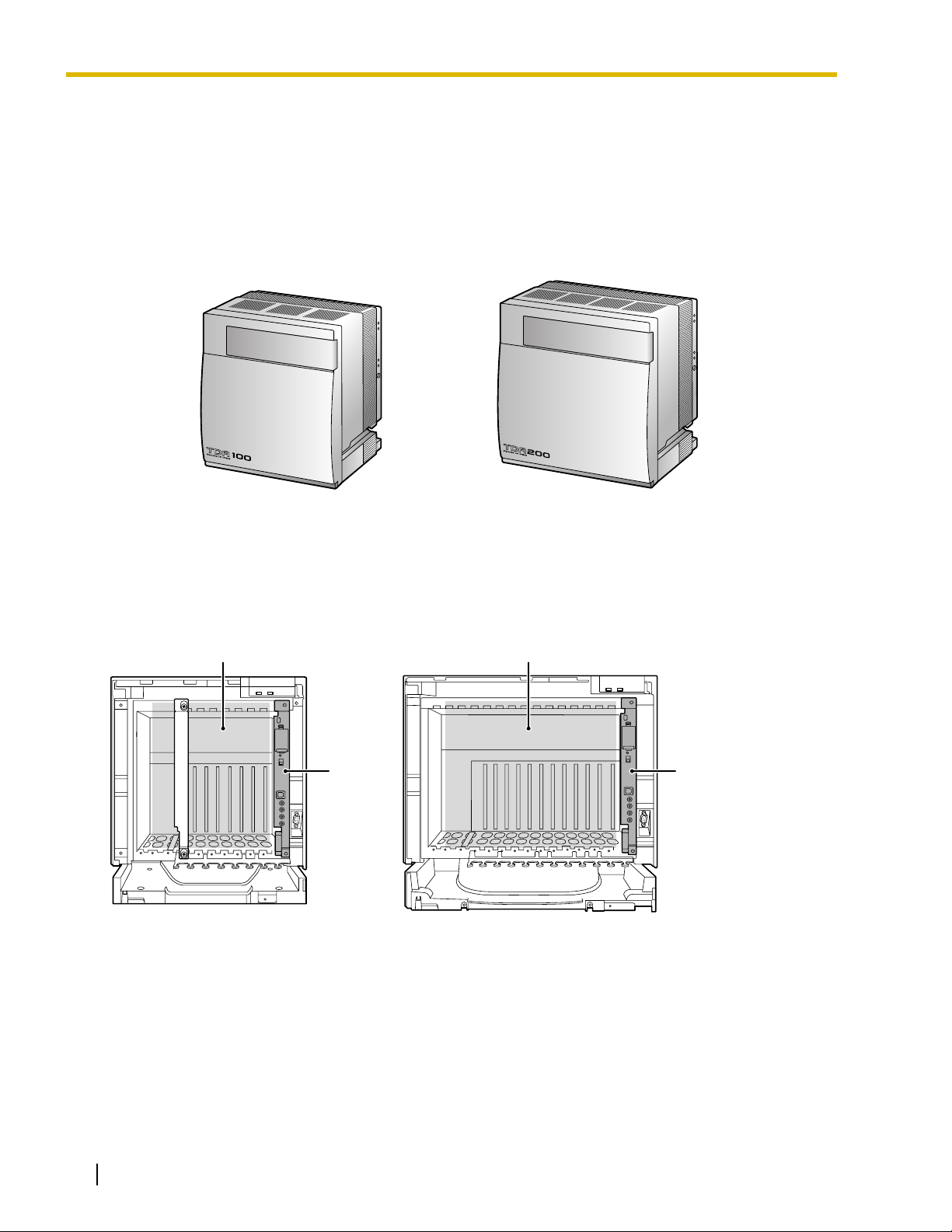
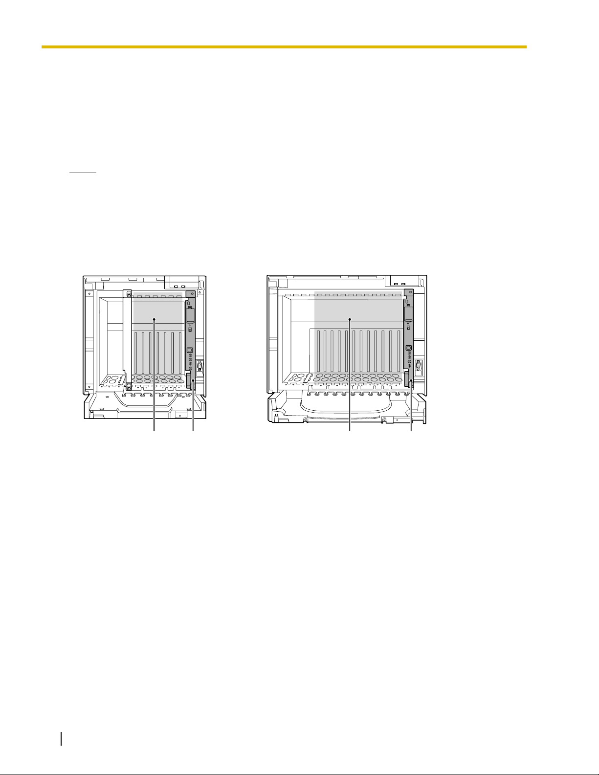
1.2.1 Basic Shelf
The basic shelf contains an MPR card for controlling the Hybrid IP-PBX. To use the system, install a power
supply unit (PSU) in the PSU Slot and optional service cards in the basic shelf.
KX-TDA100 KX-TDA200
Construction of the Basic Shelf
A: Slots for Expansion
B: MPR Card
A A
B B
22 Installation Manual
Page 23
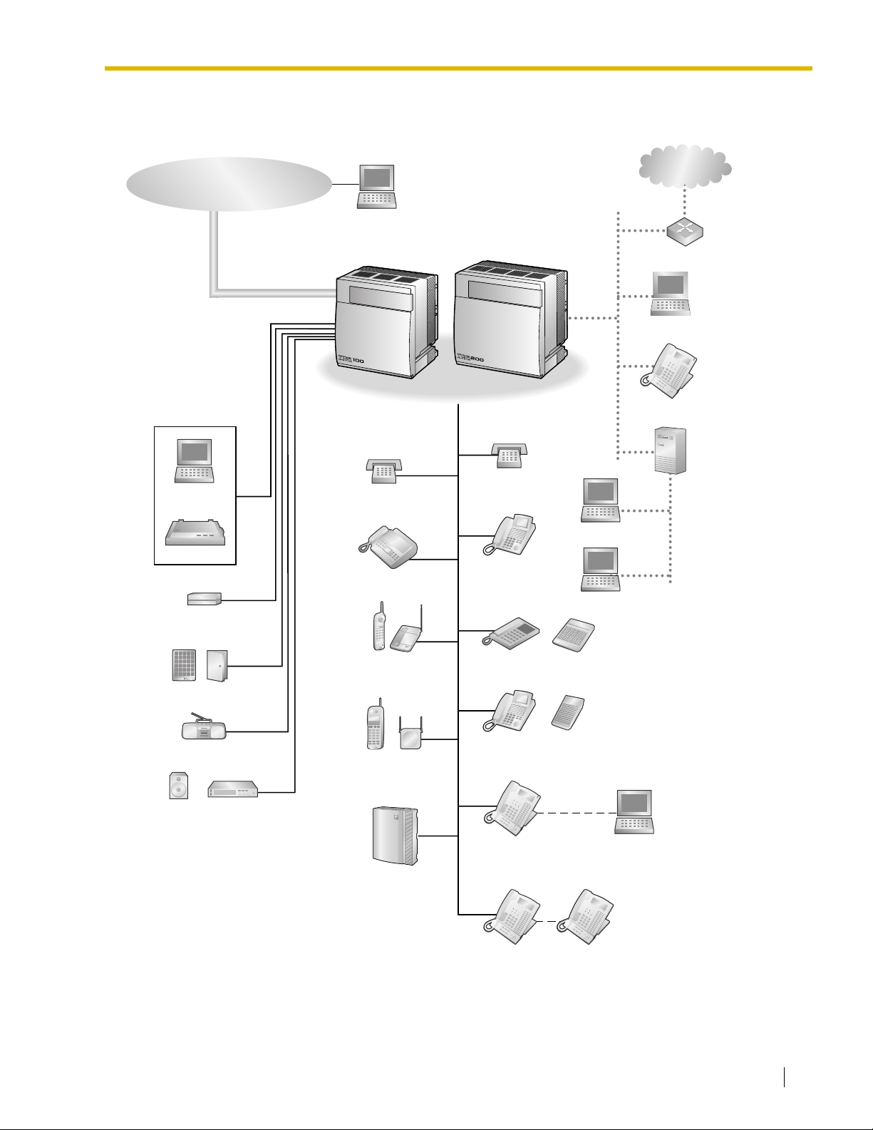
1.2.2 System Connection Diagram
CO (Telephone Company) Lines
Analog/PRI/T1
Remote PC
1.2 Basic System Construction
Private
IP Network
PC
Printer
External Sensor/
External Relay Device
Hybrid IP-PBX
SLT
Fax Machine
Wireless Phone
SLT
DPT
APT
Router
PC
IP-PT
CTI Server
PC
PC
DSS Console
Doorphone & Door Opener
BGM/Music On Hold (MOH)
Pager/
Speaker
Amplifier
CSPS
Voice Processing
System
DPT
KX-T7636/
KX-T7633
KX-T7600 DPT KX-T7600 DPT
DSS Console
USB
PC
Installation Manual 23
Page 24
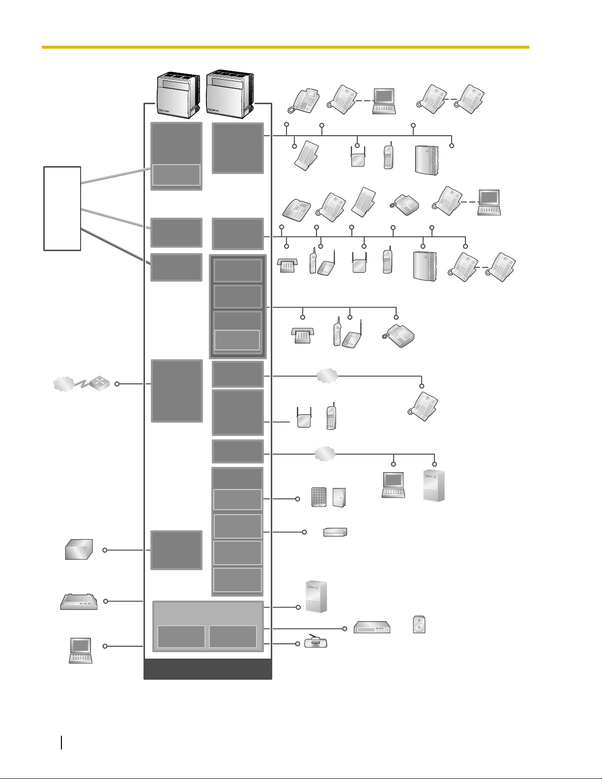
1.2 Basic System Construction
T1 Line
(Digital CO Line)
ISDN PRI Line
(Digital CO Line)
Analog
CO Line
Hybrid IP-PBX
Analog
Analog
CO Line
CO Line
Telephone
Company
Private
IP Network
Uninterruptible
Power Supply (UPS)
ISDN PRI Line
ISDN PRI Line
(Digital CO Line)
(Digital CO Line)
T1 Line
T1 Line
(Digital CO Line)
(Digital CO Line)
Router
LCOT16
(KX-TDA0181)
LCOT8
(KX-TDA0180)
CID8
(KX-TDA0193)
PRI23
(KX-TDA0290)
T1
(KX-TDA0187)
IP-GW4
(KX-TDA0480)
IP-GW4E
(KX-TDA0484)
IP-GW16
(KX-TDA0490)
PSU-S/M/L
(KX-TDA0108/
KX-TDA0104/
KX-TDA0103)
DLC16
(KX-TDA0172)
DLC8
(KX-TDA0171)
DHLC8
(KX-TDA0170)
MSLC16
(KX-TDA0175)
SLC16
(KX-TDA0174)
SLC8
(KX-TDA0173)
EXT-CID
(KX-TDA0168)
IP-EXT16
(KX-TDA0470)
CSIF4
(KX-TDA0143)
CSIF8
(KX-TDA0144)
CTI-LINK
(KX-TDA0410)
OPB3
(KX-TDA0190)
DPH4
(KX-TDA0161)
EIO4
(KX-TDA0164)
ECHO16
(KX-TDA0166)
MSG4
(KX-TDA0191)
CS
KX-T7636/
KX-T7633
PT-interface CS PS
DPT
Phone
LAN
PS
LAN
PC
DSS
Console
PT-interfaceCSPS
Fax
Machine
PC
DPT
DSS Console
APT
SLT Wireless
SLT Wireless Phone Fax Machine
Doorphone & Door Opener
External Sensor/External Relay Device
KX-T7600
DPT
KX-T7636/
KX-T7633
Voice
Processing
System
IP-PT
CTI Server
KX-T7600
DPT
Voice
Processing
System
KX-T7600
DPT
PC
KX-T7600
DPT
Station Message
Detail Recording (SMDR)
PC
24 Installation Manual
MPR
(Installed by default)
MEC
(KX-TDA0105)
Mountable Equipment
(KX-TDA0196)
CTI Server
RMT
Amplifier Pager/Speaker
Radio
Page 25

1.3 Optional Equipment
1.3.1 Optional Equipment
Model No. Model Name Description
1.3 Optional Equipment
KX-TDA0103 L-Type Power Supply Unit
(PSU-L)
KX-TDA0104 M-Type Power Supply Unit
(PSU-M)
KX-TDA0105 Memory Expansion Card
(MEC)
KX-TDA0108 S-Type Power Supply Unit
(PSU-S)
KX-TDA0143 4 Cell Station Interface Card
(CSIF4)
KX-TDA0144 8 Cell Station Interface Card
(CSIF8)
KX-TDA0161 4-Port Doorphone Card (DPH4) 4-port doorphone card for 4 doorphones and 4 door
KX-TDA0164 4-Port External Input/Output
Card (EIO4)
KX-TDA0166 16-Channel Echo Canceller
Card (ECHO16)
KX-TDA0168 Extension Caller ID Card (EXT-
CID)
Power Supply Unit for KX-TDA200. Total power output of 279
W. Safety Class 1 compliant.
Power Supply Unit for KX-TDA100 and KX-TDA200. Total
power output of 140.4 W. Safety Class 1 compliant.
Memory expansion card to increase system data storage
space and double the number of DPTs, using Digital XDP
connection. To be mounted on the MPR card.
Power Supply Unit for KX-TDA100. Total power output of 74
W. Safety Class 1 compliant.
4-port CS interface card for 4 CSs.
8-port CS interface card for 8 CSs.
openers. To be mounted on the OPB3 card.
4-port external input/output card. To be mounted on the
OPB3 card.
16-channel card for echo cancellation during conferences.
To be mounted on the OPB3 card.
Sends Caller ID signals to extension ports. To be mounted
on the SLC8 card only.
KX-TDA0170 8-Port Digital Hybrid Extension
Card (DHLC8)
KX-TDA0171 8-Port Digital Extension Card
(DLC8)
KX-TDA0172 16-Port Digital Extension Card
(DLC16)
KX-TDA0173 8-Port Single Line Telephone
Extension Card (SLC8)
KX-TDA0174 16-Port Single Line Telephone
Extension Card (SLC16)
KX-TDA0175 16-Port Single Line Telephone
Extension with Message Lamp
Card (MSLC16)
KX-TDA0180 8-Port Analog Trunk Card
(LCOT8)
8-port digital hybrid extension card for DPTs, APTs, SLTs,
DSS consoles, and PT-interface CSs, with 2 power failure
transfer (PFT) ports.
8-port digital extension card for DPTs, DSS consoles, and
PT-interface CSs.
16-port digital extension card for DPTs, DSS consoles, and
PT-interface CSs.
8-port extension card for SLTs with 2 power failure transfer
(PFT) ports.
16-port extension card for SLTs with 4 power failure transfer
(PFT) ports.
16-port extension card for SLTs with Message Waiting Lamp
control and 4 power failure transfer (PFT) ports. Maximum
output of 145 V/85 V for Message Waiting Lamp control.
8-port analog CO line card with 2 power failure transfer (PFT)
ports.
Installation Manual 25
Page 26

1.3 Optional Equipment
Model No. Model Name Description
KX-TDA0181 16-Port Analog Trunk Card
(LCOT16)
16-port analog CO line card with 4 power failure transfer
(PFT) ports.
KX-TDA0187 T-1 Trunk Card (T1) 1-port T1 CO line card. EIA/TIA standard compliant.
KX-TDA0190 Optional 3-Slot Base Card
(OPB3)
Optional 3-slot base card for mounting a maximum of 3
optional service cards from the following: MSG4, DPH4, or
ECHO16 card.
KX-TDA0191 4-Channel Message Card
4-channel message card. To be mounted on the OPB3 card.
(MSG4)
KX-TDA0193 8-Port Caller ID Card (CID8) 8-port Caller ID signal type FSK/FSK (with Call Waiting
Caller ID [Visual Caller ID])/DTMF. To be mounted on the
LCOT8/LCOT16 cards.
KX-TDA0196 Remote Card (RMT) Analog modem card for remote communication with the
Hybrid IP-PBX. ITU-T V.90 support. To be mounted on the
MPR card.
KX-TDA0290 PRI Card (PRI23) 1-port ISDN Primary Rate Interface card (23B channels). NI
(North American standard ISDN protocol) compliant.
KX-TDA0410 CTI Link Card (CTI-LINK) Ethernet card for CTI communication via 10BASE-T port.
CSTA Phase 3 protocol compatible.
KX-TDA0470 16-Channel VoIP Extension
Card (IP-EXT16)
16-channel VoIP extension card. Compliant with Panasonic
proprietary protocol, and ITU-T G.729a and G.711 CODEC
methods.
KX-TDA0480 4-Channel VoIP Gateway Card
(IP-GW4)
KX-TDA0484 4-Channel VoIP Gateway Card
(IP-GW4E)
KX-TDA0490 16-Channel VoIP Gateway
Card (IP-GW16)
KX-TDA0920 SD Memory Card for Software
Upgrade to Enhanced Version
Note
For the maximum number of optional service cards that can be installed in the Hybrid IP-PBX, refer to
"1.4.3 System Capacity".
4-channel VoIP gateway card. Compliant with VoIP H.323
V.2 protocol, and ITU-T G.729a, and G.723.1 CODEC
methods. G3 fax support.
4-channel VoIP gateway card. Compliant with VoIP H.323
V.2 protocol, and ITU-T G.729a, G.723.1, and G.711
CODEC methods.
16-channel VoIP gateway card. Compliant with VoIP H.323
V.2 protocol, and ITU-T G.729a, G.723.1, and G.711
CODEC methods.
Optional SD Memory Card to use enhanced features. For
more details, refer to the SD Memory Card Installation/
Upgrade Guide.
26 Installation Manual
Page 27

1.4 Specifications
1.4 Specifications
1.4.1 General Description
Control Bus Original bus (16-bit, 8 MHz, 10 megabytes per second)
Communication Bus H.100 bus conformity (1024 time slots)
Switching Non-blocking
Power Input PSU-S 100 V AC to 130 V AC, 1.4 A/200 V AC to 240 V AC, 0.8 A,
50 Hz/60 Hz
PSU-M 100 V AC to 130 V AC, 2.5 A/200 V AC to 240 V AC, 1.4 A,
50 Hz/60 Hz
PSU-L 100 V AC to 130 V AC, 5.1 A/200 V AC to 240 V AC, 2.55 A,
50 Hz/60 Hz
Maximum Power Failure Tolerance
Power Consumption KX-TDA100 with PSU-S 140 W, 1.4 A (at 120 V AC, 60 Hz)
*1
300 ms
KX-TDA100 with PSU-M 210 W, 2.2 A (at 120 V AC, 60 Hz)
KX-TDA200 with PSU-M 240 W, 2.5 A (at 120 V AC, 60 Hz)
KX-TDA200 with PSU-L 490 W, 5.1 A (at 120 V AC, 60 Hz)
Memory Backup Duration 7 years
Dialing CO Line Dial Pulse (DP) 10 pps, 20 pps
Tone (DTMF) Dialing
Extension Dial Pulse (DP) 10 pps, 20 pps
Tone (DTMF) Dialing
Mode Conversion DP-DTMF, DTMF-DP
Ring Frequency 20 Hz/25 Hz (selectable)
Central Office Loop Limit 1600 Ω maximum
Operating
Environment
Conference Call CO Line From 10 × 3-party conference call to 4 × 8-party conference
Music on Hold (MOH) 2 ports (Level Control: -11 dB to +11 dB in 1 dB steps)
Temperature 0 °C to 40 °C (32 °F to 104 °F)
Humidity 10 % to 90 % (non-condensing)
call
MOH1: External Music Source port
MOH2: Selectable Internal/External Music Source port
Paging Internal Level Control: -15 dB to +6 dB in 3 dB steps
External 2 ports (Volume Control: -15 dB to +15 dB in 1 dB steps)
Serial Interface Port RS-232C 1 (maximum 115.2 kbps)
USB 1
Installation Manual 27
Page 28

1.4 Specifications
Extension Connection Cable SLT 1-pair wire (T, R)
DPT 1-pair wire (D1, D2) or
2-pair wire (T, R, D1, D2)
APT 2-pair wire (T, R, D1, D2)
PT-interface CS 1-pair wire (D1, D2)
DSS Console and Add-on
1-pair wire (D1, D2)
Key Module
Dimension KX-TDA100 334 mm (W) × 390 mm (H) × 270 mm (D)
(13-1/3 in × 15-3/5 in × 10-4/5 in)
KX-TDA200 430 mm (W) × 415 mm (H) × 270 mm (D)
(17-1/5 in × 16-3/5 in × 10-4/5 in)
Weight (when fully
mounted)
*1
If tolerance may be exceeded, an Uninterruptible Power Supply (UPS) is recommended.
KX-TDA100 Under 12 kg (26.4 lb)
KX-TDA200 Under 16 kg (35.2 lb)
28 Installation Manual
Page 29

1.4 Specifications
1.4.2 Characteristics
Terminal Equipment Loop Limit • PT: KX-T7600 series DPT: 90 Ω; all other DPTs/APTs: 40 Ω
• SLT: 600 Ω including set
• Doorphone: 20 Ω
• CS: 130 Ω; PT-interface CS: 65 Ω
Minimum Leakage Resistance 15 000 Ω minimum
Maximum Number of Extension
Instruments per Line
Ring Voltage 75 Vrms at 20 Hz/25 Hz depending on the Ringing Load
Central Office Loop Limit 1600 Ω maximum
Hookswitch Flash Timing
Range
Door Opener Current Limit 24 V DC/30 V AC, 1 A maximum
External Relay Current Limit 24 V DC/30 V AC, 1 A maximum
External Sensor Current Limit Power to the external sensor is provided from the EIO4 card and must be
Paging Terminal Impedance 600 Ω
MOH (Music on Hold) Terminal
Impedance
1 for PT or SLT
2 by Parallel or eXtra Device Port connection of an APT/DPT and an SLT
3 by Digital eXtra Device Port connection of 2 DPTs and an SLT
24 ms to 2032 ms
grounded through the EIO4 card. For the connection diagram, refer to "2.6.3
EIO4 Card (KX-TDA0164)". The Hybrid IP-PBX detects input from the sensor
when the signal is under 100 Ω.
10 000 Ω
Installation Manual 29
Page 30
1.4 Specifications
1.4.3 System Capacity
Maximum Optional Service Cards
There are 2 types of optional service cards for installation:
• Cards installed in the slots of the Hybrid IP-PBX
• Cards mounted on other optional service cards
Notes
• Any card that exceeds the capacity of the Hybrid IP-PBX will be ignored.
• When the Hybrid IP-PBX starts up with an invalid configuration, some cards will be ignored.
Cards Installed in the Slots of the Hybrid IP-PBX
KX-TDA100 KX-TDA200
AB C B
Free Slots 1 to 6 (from the left)
A.
B. MPR Card Slot
C. Free Slots 1 to 11 (from the left)
30 Installation Manual
Page 31

1.4 Specifications
The following number of optional service cards can be installed in the various slots of the Hybrid IP-PBX.
Card Type
Installed in
KX-TDA100 KX-TDA200
MPR 1 1 MPR Card Slot
Maximum Number
CO Line Card
To ta l 6
*1
To t a l 8
*2
LCOT4
LCOT8
68
LCOT16
T1
44
PRI23
IP-GW4
IP-GW4E
44
IP-GW16
Extension Card Total 6 Total 8
Free Slot
DHLC8
DLC8
DLC16
SLC8
68
SLC16
MSLC16
IP-EXT16
CSIF4
44
CSIF8
OPB3 4 4
CTI-LINK 1 1
*1
When installing T1, PRI23, or IP-GW4 cards, make sure that the number of these cards × 2 + the number of other cards (including
IP-GW4E cards) does not exceed 8.
*2
One T1, PRI23, or IP-GW4 card counts as 2 cards. However, one IP-GW4E card counts as 1 card.
Installation Manual 31
Page 32

1.4 Specifications
Cards Mounted on Other Optional Service Cards
The following number of optional service cards can be mounted on the specified other optional service
cards.
Card Type
Mounted on
KX-TDA100 KX-TDA200
MEC 1 1
MPR Card
RMT 1 1
CID8 12 16 LCOT8 Card/LCOT16 Card
EXT-CID 6 8 SLC8 Card
DPH4 4 4
Maximum Number
ECHO16
*1
2
*1
2
OPB3 Card
MSG4 4 4
EIO4 4 4
*1
Only 1 ECHO16 card can be mounted on each OPB3 card.
Maximum Terminal Equipment
The following number of items of terminal equipment can be supported by the Hybrid IP-PBX. For how to
count the total number of items of equipment to be connected, refer to "MEC Card Calculation".
KX-TDA100 KX-TDA200
Terminal Equipment Type
Without MEC
Card
With MEC
Card
Without MEC
Card
With MEC
Card
Telephone 64 160 128 256
SLT 64 96 128 128
KX-T7600 series DPT 64 128 128 256
Other DPT 32 32 128 128
APT 24246464
IP-PT 64
96 128 128
DSS console 8 8
CS 32 32
PS 128 128
Voice Processing System (VPS) 2 2
Doorphone 16 16
Door Opener 16 16
External Sensor 16 16
External Relay 16 16
32 Installation Manual
Page 33

1.4 Specifications
MEC Card Calculation
Calculate the MEC figure from the type and total number of items of equipment to be connected. If the MEC
figure exceeds 64 (for KX-TDA100) or 128 (for KX-TDA200), you need to install an MEC card.
MEC Card Calculation
Equipment Type MEC Figure
PT KX-T7600 series DPT/KX-T7600 series DSS
console
Other DPT/Other DSS console 1
APT 1
IP-PT 1
Extension Card
*1
DHLC8 8
SLC8 8
SLC16 16
MSLC16 16
CS (1 unit) 0
PT-interface CS (1 unit) 0
VPS (1 port) 1
*1
Only the extension cards that can support SLTs count for the MEC figures.
Calculation Example (KX-TDA100)
Equipment Type MEC Figure
1
KX-T7600 series DPT 48 units 48
SLC16 1 card 16
MSLC16 1 card 16
VPS 8 ports 8
To ta l 88
The total MEC figure is 88. As this exceeds 64, you need to install an MEC card for this configuration.
Installation Manual 33
Page 34

1.4 Specifications
Power Supply Unit Selection
Hybrid IP-PBX needs a power supply unit (PSU) suitable for its configuration. Calculate the load figure from
the type and number of items of equipment to be connected, and determine the type of PSU that will be
required.
Load Figure Calculation
Equipment Type Load Figure
PT KX-T7600 series DPT/KX-T7600 series DSS
console
Other DPT/Other DSS console 4
APT 4
IP-PT 0
Extension Card
*1
DHLC8 8
SLC8 8
SLC16 16
MSLC16 16
CS (1 unit) 4
PT-interface CS (1 unit) 4
VPS (1 port) 1
*1
Only the extension cards that can support SLTs count for the load figures.
PSU Capacity
Each PSU supports a different load figure.
PSU Type Maximum Load Figure
PSU-S
PSU-M
PSU-L
*1
*2
*3
64
128
512
1
*1
Available for the KX-TDA100
*2
Available for the KX-TDA100 and KX-TDA200
*3
Available for the KX-TDA200
34 Installation Manual
Page 35

1.4 Specifications
Calculation Example (KX-TDA200)
Equipment Type Load Figure
KX-T7600 series DPT 48 units 48
Other DPT 2 units 8
SLC16 1 card 16
MSLC16 1 card 16
VPS 8 ports 8
To ta l 96
The total load figure is 96. As this is between 64 and 128, you should install the PSU-M. However, if you
expect expansion in the future, it may be better to install the PSU-L. There is no harm in installing a PSU
that is larger than is required for the current configuration.
Installation Manual 35
Page 36

1.4 Specifications
36 Installation Manual
Page 37

Section 2
Installation
This section describes the procedures to install the Hybrid IPPBX. Detailed instructions for planning the installation site,
installing the shelves and optional service cards, and cabling
of peripheral equipment are provided. Further information on
system expansion and peripheral equipment installation is
included.
Installation Manual 37
Page 38

2.1 Before Installation
2.1 Before Installation
2.1.1 Before Installation
Please read the following notes concerning installation and connection before installing the Hybrid IP-PBX
and terminal equipment.
Be sure to comply with all applicable laws, regulations, and guidelines.
Safety Installation Instructions
When installing telephone wiring, basic safety precautions should always be followed to reduce the risk of
fire, electric shock and injury to persons, including the following:
1. Never install telephone wiring during a lightning storm.
2. Never install telephone jacks in wet locations unless the jack is specifically designed for wet locations.
3. Never touch uninsulated telephone wires or terminals unless the telephone line has been disconnected
at the network interface.
4. Use caution when installing or modifying telephone lines.
5. Anti-static precautions should be taken during installation.
Installation Precautions
This set is made for wall mounting (KX-TDA100/KX-TDA200) or floor standing (KX-TDA200 only), and
should be installed in a location where it is accessible for inspections and maintenance.
To prevent malfunction, noise, or discoloration, avoid installing the system in the following locations:
1. In direct sunlight and hot, cold, or humid places. Temperature range: 0 °C to 40 °C (32 °F to 104 °F)
2. Areas where sulfuric gases may be present, such as near thermal springs.
3. Areas where shocks or vibrations are frequent or strong.
4. High-dust areas, or places the system may come into contact with water or oil.
5. Near devices that generate high frequencies, such as sewing machines or electric welders.
6. On or near computers, telexes, or other office equipment, as well as microwave ovens or air
conditioners. (It is preferable not to install the system in the same room as the above equipment.)
7. Within 1.8 m (6 ft) of radios and televisions. (Both the Hybrid IP-PBX and PTs should be at least 1.8 m
(6 ft) away from such devices).
8. Locations where other objects will obstruct the area around the Hybrid IP-PBX. Be especially careful
to leave at least 20 cm (8 in) of space above and 10 cm (4 in) to the sides of the Hybrid IP-PBX for
ventilation.
9. Do not block the openings of the Hybrid IP-PBX.
10. Do not stack up the optional service cards.
Wiring Precautions
Be sure to follow these instructions when wiring the unit:
1. Do not run unshielded telephone cables near AC power cables, computer cables, AC power sources,
etc. When running cables near other noise-generating devices or cables, use shielded telephone
cables or shield the telephone cables with metal tubing.
2. If cables are run on the floor, use protectors to prevent the cables from being stepped on. Avoid running
cables under carpets.
38 Installation Manual
Page 39

2.1 Before Installation
3. Avoid using the same AC outlet for computers, telexes, and other office equipment, as noise generated
by such equipment may hamper system performance or interrupt the system.
4. Use 2-pair telephone cables when connecting PTs.
Use 1-pair telephone cables when connecting SLTs, data terminals, answering machines, computers,
Voice Processing Systems, etc.
5. Unplug the system from its power source when wiring, and plug the system back in only after all wiring
is completed.
6. Mis-wiring may cause the Hybrid IP-PBX to operate improperly. Refer to Section 2 "Installation" when
wiring the system.
7. If an extension does not operate properly, disconnect the telephone from the extension line and connect
it again, or turn off the Hybrid IP-PBX using the power switch, then turn it on again.
8. For safety purposes this unit is equipped with a grounded plug. If you do not have a grounded outlet,
please have one installed. Do not bypass this safety feature by tampering with the plug.
9. Use twisted pair cable for CO line connection.
10. CO lines should be installed with surge protectors. For details, refer to "2.2.13 Surge Protector
Installation".
11. To assure good quality telephone connection, it is recommended new and modifications to existing
installation of customer premise wiring shall use solid twisted pair copper conductors with minimum 24
gauge that comply with the electrical specifications for Category 3 wiring as detailed in ANSI/EIA/TIA570A Building Wiring Standards.
Installation Manual 39
Page 40

2.2 Installation of the Hybrid IP-PBX
2.2 Installation of the Hybrid IP-PBX
2.2.1 Unpacking
Unpack the box and check the items below:
KX-TDA100 KX-TDA200
Main Unit 1 1
Metal Bracket 1 1
Screw A 3 4
Screw B (Black) 2 6
Anchor Plug 3 4
Mini Plug (for pager and music source) 4 4
SD Memory Card 1 1
40 Installation Manual
Page 41

2.2.2 Names and Locations
Inside View
KX-TDA100 KX-TDA200
2.2 Installation of the Hybrid IP-PBX
D
C
B
A
F
GIEEHH
A. RUN Indicator
B. ALARM Indicator
C. USB Port
D. RS-232C Port
E. PSU Slot
F. Null Slot (not available for any optional service card)
G. Free Slots 1 to 6 (from the left)
H. MPR Card Slot
I. Free Slots 1 to 11 (from the left)
D
C
B
A
Installation Manual 41
Page 42

2.2 Installation of the Hybrid IP-PBX
2.2.3 Opening/Closing the Front Cover
Opening the Front Cover
1. Insert a flathead screwdriver into the opening (on the left of the screw cover) and unlatch the screw
cover.
Screw Cover
2. Turn the screw counterclockwise to loosen.
3. Slide the front cover to the right until it stops, then lift the front cover.
42 Installation Manual
Page 43

2.2 Installation of the Hybrid IP-PBX
Closing the Front Cover
1. Hook the front cover onto the shelf (line up the protrusions on the cover with the receptacles on the
shelf). Then slide the front cover to the left until it locks.
2. Turn the screw clockwise to tighten.
3. Secure the screw cover.
2
1
Notes
• For safety reasons, close the front cover and tighten the screw before operating the Hybrid IP-PBX.
• Do not forget to tighten the screw before securing the screw cover.
Installation Manual 43
Page 44

2.2 Installation of the Hybrid IP-PBX
2.2.4 Installing/Replacing the Power Supply Unit
Function
PSU Type Lower/Upper Input Voltage Range Current Input Frequency
PSU-S
(for KX-TDA100)
PSU-M
(for KX-TDA100/200)
PSU-L
(for KX-TDA200)
Power Switch
Ground Terminal
AC Inlet
Lower: 100 V AC to 130 V AC 1.4 A
Upper: 200 V AC to 240 V AC 0.8 A
Lower: 100 V AC to 130 V AC 2.5 A
50 Hz or 60 Hz
Upper: 200 V AC to 240 V AC 1.4 A
Lower: 100 V AC to 130 V AC 5.1 A
Upper: 200 V AC to 240 V AC 2.55 A
PSU-S PSU-M/PSU-L
Ground Terminal
Power Switch
AC Inlet
Accessories and User-supplied Items
Accessories (included): Screws × 4, AC power cord × 1
User-supplied (not included): Grounding wire
Note
For details about frame ground connection, refer to "2.2.5 Frame Ground Connection".
Safety Instructions
Each PSU complies with Safety Class 1 of IEC60950, EN60950, UL60950,
CAN/CSA-C22.2 No.60950, and AS/NZS60950; therefore a protective ground connection exists between
the mains outlet ground and the PSU case. To ensure the PBX chassis is safely grounded, it is essential
that the PSU case be securely fastened to the PBX chassis with the 4 screws provided with each PSU.
When installing or replacing a PSU, basic safety precautions should always be followed to reduce the risk
of fire, electric shock and injury to persons, including the following:
1. Never install or replace a PSU during a lightning storm.
2. Never install or replace a PSU in wet locations.
3. Never install or replace a PSU unless at least 20 s has elapsed after the AC supply is disconnected.
44 Installation Manual
Page 45

2.2 Installation of the Hybrid IP-PBX
4. To protect the back board from static electricity, do not touch parts on the back board in the main
unit and PSU. To discharge static electricity, touch ground or wear a grounding strap.
The following procedures are for installing or replacing a PSU only. Do not replace or remove the
PSU for any other purpose.
Installing the Power Supply Unit
1. Insert the PSU along the guide rails.
CAUTION
For safety reasons, do not touch parts in the PSU.
Guide Rail
2. Push the release lever in the direction of the arrow, so that the PSU engages securely with the
connector on the back board.
Back Board
Release Lever
Installation Manual 45
Page 46

2.2 Installation of the Hybrid IP-PBX
3. Turn the 4 screws clockwise, in the order indicated by the numbers 1 to 4, to fix the PSU.
2
3
Screws
4
1
Replacing the Power Supply Unit
1. Unplug the AC power cord.
2. Turn the 4 screws counterclockwise to loosen them.
Screws
46 Installation Manual
Page 47

2.2 Installation of the Hybrid IP-PBX
3. Pull the release lever in the direction of the arrow to disconnect the PSU from the back board.
Back Board
Release Lever
4. Replace the PSU.
New PSU
Current PSU
5. Follow the steps in "Installing the Power Supply Unit".
Installation Manual 47
Page 48

2.2 Installation of the Hybrid IP-PBX
2.2.5 Frame Ground Connection
IMPORTANT
Connect the frame of the Hybrid IP-PBX to ground.
1. Loosen the screw.
2. Insert a grounding wire (user-
supplied)*.
Screw
3. Tighten the screw.
4. Connect the grounding wire to
ground.
* For grounding wire, green-and-yellow insulation is required, and the cross-sectional area of the
conductor must be more than 0.75 mm
• Be sure to comply with applicable local regulations (e.g., laws, guidelines).
• Proper grounding (connection to ground) is very important to protect the Hybrid IP-PBX from the bad
effects of external noise or to reduce the risk to the user of electrocution in the case of a lightning strike.
• The ground wire of the AC cable has an effect against external noise and a lightning strikes, but it may
not be enough to protect the Hybrid IP-PBX. A permanent connection between ground and the ground
terminal of the Hybrid IP-PBX must be made.
In most of the continental United States, the ground provided by the "Third wire ground" at the commercial
power outlet will be satisfactory. However, in a small percentage of cases this ground may be installed
incorrectly. Therefore, the following test procedure should be performed.
Grounding
wire
To Ground
2
or 18 AWG.
Test Procedure
1. Obtain a suitable voltmeter and set it for a possible reading of up to 250 V AC.
2. Connect the meter probes between the 2 main AC voltage points on the wall outlet. The reading
obtained should be 108 V AC to 132 V AC.
3. Move one of the meter probes to the 3rd prong terminal (GND).
Either the same reading or a reading of 0 volt should be obtained.
4. If a reading of 0 volt at one terminal and a reading of 108 V AC to 132 V AC at the other terminal
is not obtained, the outlet is not properly grounded.
This condition should be corrected by a qualified electrician (per article 250 of the National
Electrical Code).
5. If a reading of 0 volt at one terminal and a reading of 108 V AC to 132 V AC at the other terminal
is obtained, then set the meter to the "OHMS/RX1" scale, place one probe at the GND Terminal
and the other probe at the terminal which gave a reading of 0 volt.
A reading of less than 1 ohm should be obtained. If the reading is not obtained, the outlet is not
adequately grounded. See qualified electrician.
48 Installation Manual
Page 49

2.2 Installation of the Hybrid IP-PBX
2.2.6 Installing/Removing the Optional Service Cards
CAUTION
To protect the back board from static electricity, do not touch parts on the back board in the main unit
and on the optional service cards. To discharge static electricity, touch ground or wear a grounding
strap.
Note
The optional service cards can be installed or removed while the DC power is supplied. However, when
installing or removing the MPR card, the DC power supply must be turned off.
Installing Optional Service Cards
1. Insert the card along the guide rails.
Guide Rail
Installation Manual 49
Page 50

2.2 Installation of the Hybrid IP-PBX
2. Holding the card as shown below, push the release lever in the direction of the arrow so that the card
engages securely with the connector on the back board.
Back Board
Release Lever
3. Turn the 2 screws clockwise to fix the card in place.
Screws
Note
Make sure the screws are tightened to ground the card securely.
50 Installation Manual
Page 51

2.2 Installation of the Hybrid IP-PBX
Covering the Blank Slots
Be sure to cover each slot in which no optional service card is installed by using a Blank Slot Cover.
CAUTION
Failure to install the Blank Slot Cover may cause electromagnetic interference.
Installation Manual 51
Page 52

2.2 Installation of the Hybrid IP-PBX
Handling of the Cables
When cables are connected to the Hybrid IP-PBX, run the cables to either the right or the left and then
towards the back of the shelf as shown below.
1
2
4
3
Note
For safety reasons, do not stretch, bend, or pinch the AC power cord.
52 Installation Manual
Page 53

2.2 Installation of the Hybrid IP-PBX
Removing the Optional Service Cards
1. Turn the 2 screws counterclockwise to loosen them.
Screws
2. Pull the release lever in the direction of the arrow to disconnect the card from the back board. Pull the
card from the shelf to remove it.
Back Board
Release Lever
Installation Manual 53
Page 54

2.2 Installation of the Hybrid IP-PBX
2.2.7 Types of Connectors
Connector Type Pin Number Used for
RJ11
(Twisted pair cable)
RJ45
(Twisted pair cable)
Amphenol
Type A Type B
(Shielded twisted pair
cable)
50 25
26 1
• DHLC8 (KX-TDA0170)
• SLC8 (KX-TDA0173)
1
4
• SLC16 (KX-TDA0174)
• MSLC16 (KX-TDA0175)
• LCOT8 (KX-TDA0180)
• LCOT16 (KX-TDA0181)
• CSIF4 (KX-TDA0143)
• CSIF8 (KX-TDA0144)
8
• T1 (KX-TDA0187)
• PRI23 (KX-TDA0290)
1
• CTI-LINK (KX-TDA0410)
• IP-EXT16 (KX-TDA0470)
• IP-GW4 (KX-TDA0480)
• IP-GW4E (KX-TDA0484)
• IP-GW16 (KX-TDA0490)
• DHLC8 (KX-TDA0170)
• DLC8 (KX-TDA0171)
• DLC16 (KX-TDA0172)
• SLC8 (KX-TDA0173)
• SLC16 (KX-TDA0174)
• MSLC16 (KX-TDA0175)
• LCOT8 (KX-TDA0180)
• LCOT16 (KX-TDA0181)
10-pin
Terminal
Block
54 Installation Manual
8-pin
Terminal
Block
10
1
1
• EIO4 (KX-TDA0164)
8
• DPH4 (KX-TDA0161)
Page 55

2.2 Installation of the Hybrid IP-PBX
Connector Type Pin Number Used for
• IP-GW4 (KX-TDA0480)
RS-232C
6 1
9 5
•Basic Shelf
•MPR
USB
2
3
4
1
Mini Plug
•MPR
2
4
Installation Manual 55
Page 56

2.2 Installation of the Hybrid IP-PBX
2.2.8 Attaching a Ferrite Core
A ferrite core must be attached when:
• connecting IP-GW16 and IP-EXT16 cards using an RJ45 connector, or
• connecting extension cards using an Amphenol connector.
The ferrite core is included with the card.
When connecting an IP-GW16/IP-EXT16 card
Wrap the cable once around the ferrite core, then close the case of the ferrite core. Attach the ferrite core 5
cm (1-15/16 in) away from the connector.
5 cm
(1-15/16 in)
When connecting an extension card
Pass the cable through the ferrite core, then close the case of the ferrite core. Attach the ferrite core 3 cm
(1-3/16 in) away from the connector.
3 cm
(1-3/16 in)
56 Installation Manual
Page 57

2.2 Installation of the Hybrid IP-PBX
If you need to open the ferrite core, use a flathead screwdriver to unlatch the case of the ferrite core.
Installation Manual 57
Page 58

2.2 Installation of the Hybrid IP-PBX
2.2.9 Fastening Amphenol Connector
An Amphenol 57JE-type connector is used on some of the optional service cards.
To connect an Amphenol connector, use the spring latch or screw to fix the upper part and use Velcro® tape
to fix the lower part of the connector.
Type A (Spring Latch + Velcro Tape)
Velcro
Tape
Spring
Latch
1
Type B (Screw + Velcro Tape)
Velcro
Tape
Spring
Latch
1
2
1
Insert the screw (included
with the Amphenol or
optional service card).
Remove the
screw on the
optional service
card.
58 Installation Manual
2
2
Page 59

2.2 Installation of the Hybrid IP-PBX
Amphenol Connector Pin Assignment Chart
Below is an Amphenol connector pin assignment chart for all optional service cards that use the Amphenol
connector. For more details, refer to the appropriate section in "2.4 Information about the CO Line Cards"
and "2.5 Information about the Extension Cards".
Pin No. LCOT8 LCOT16 DHLC8 DLC8 DLC16 MSLC16 SLC16 SLC8
1RARARA D2A RA RA RA
26 TA TA TA D1A TA TA TA
2 RB RB D2A D2A D2B RB RB
27 TB TB D1A D1A D1B TB TB
3RCRC D2C RC RC
28 TC TC D1C TC TC
4RDRDRB D2D RD RD RB
29 TD TD TB D1D TD TD TB
5 RE RE D2B D2B D2E RE RE
30 TE TE D1B D1B D1E TE TE
6RFRF D2F RF RF
31 TF TF D1F TF TF
7RGRGRC D2G RG RG RC
32 TG TG TC D1G TG TG TC
8 RH RH D2C D2C D2H RH RH
33 TH TH D1C D1C D1H TH TH
9 RI D2I RI RI
34 TI D1I TI TI
10 RJ RD D2J RJ RJ RD
35 TJ TD D1J TJ TJ TD
11 RK D2D D2D D2K RK RK
36 TK D1D D1D D1K TK TK
12 RL D2L RL RL
37 TL D1L TL TL
13 RM RE D2M RM RM RE
38 TM TE D1M TM TM TE
14 RN D2E D2E D2N RN RN
39 TN D1E D1E D1N TN TN
15 RO D2O RO RO
40 TO D1O TO TO
16 RP RF D2P RP RP RF
41 TP TF D1P TP TP TF
17 D2F D2F
42 D1F D1F
18
43
19 RG RG
44 TG TG
20 D2G D2G
45 D1G D1G
21
46
22 RH RH
47 TH TH
23 D2H D2H
48 D1H D1H
24
49
25
50
Installation Manual 59
Page 60

2.2 Installation of the Hybrid IP-PBX
2.2.10 Wall Mounting (KX-TDA200)
CAUTION
• Make sure that the wall the shelf will be attached to is capable of supporting at least 4 times the
weight of the shelf.
• Drive mounting screws into the wall. Be careful to avoid touching any metal laths, wire laths or
metal plates in the wall.
Notes
• Do not block the openings of the shelf. Allow space of at least 20 cm (8 in) above and 10 cm (4 in)
at the sides of the shelf.
• Make sure that the surface behind the shelf is flat and free of obstacles, so that the openings on
the back of the shelf will not be blocked.
• Make sure that the surface behind the shelf is not made of wood.
• Be careful not to drop the shelf.
1. Install 4 anchor plugs in the wall, using the metal bracket as a template. Fix the metal bracket with 4
screws (A).
Metal Bracket
Screw (A)
Anchor Plug
Wall
Hammer
Screw (A)
Metal Bracket
Anchor Plug
8 mm
(5/16 in)
30 mm
(1-3/16 in)
60 Installation Manual
Page 61

2.2 Installation of the Hybrid IP-PBX
2. Hook the shelf onto the metal bracket, making sure that the shelf slides down and onto the hooked parts
of the metal bracket. Use 2 screws (B) to fix both sides of the shelf.
T
O
P
Screw (B)
Installation Manual 61
Page 62

2.2 Installation of the Hybrid IP-PBX
2.2.11 Wall Mounting (KX-TDA100)
CAUTION
• Make sure that the wall the shelf will be attached to is capable of supporting at least 4 times the
weight of the shelf.
• Drive mounting screws into the wall. Be careful to avoid touching any metal laths, wire laths or
metal plates in the wall.
Notes
• Do not block the openings of the shelf. Allow space of at least 20 cm (8 in) above and 10 cm (4 in)
at the sides of the shelf.
• Make sure that the surface behind the shelf is flat and free of obstacles, so that the openings on
the back of the shelf will not be blocked.
• Make sure that the surface behind the shelf is not made of wood.
• Be careful not to drop the shelf.
1. Install 3 anchor plugs in the wall, using the metal bracket as a template. Fix the metal bracket with 3
screws (A).
Metal Bracket
Screw (A)
Anchor Plug
TOP
TOP
Wall
Hammer
Screw (A)
Metal Bracket
Anchor Plug
8 mm
(5/16 in)
30 mm
(1-3/16 in)
62 Installation Manual
Page 63

2.2 Installation of the Hybrid IP-PBX
2. Hook the shelf onto the metal bracket, making sure that the shelf slides down and onto the hooked parts
of the metal bracket. Use 2 screws (B) to fix both sides of the shelf.
TOP
Screw (B)
Installation Manual 63
Page 64

2.2 Installation of the Hybrid IP-PBX
2.2.12 Floor Standing (KX-TDA200 Only)
Notes
• Do not block the openings of the shelf. Allow space of at least 20 cm (8 in) above and 10 cm (4 in)
at the sides of the shelf.
• Make sure that the surface behind the shelf is flat and free of obstacles, so that the openings on
the back of the shelf will not be blocked.
• Make sure that the surface behind the shelf is not made of wood.
• Be careful not to drop the shelf.
1. Install 4 anchor plugs in the floor, using the metal bracket as a template. Fix the metal bracket with 4
screws (A).
Screw (A) Metal Bracket
TOP
Screw (A)
Anchor
Plug
Floor
Hammer
Anchor
Plug
30 mm
(1-3/16 in)
8 mm
(5/16 in)
2. Remove the front cover of the shelf (refer to "2.2.3 Opening/Closing the Front Cover").
Metal
Bracket
64 Installation Manual
Page 65

2.2 Installation of the Hybrid IP-PBX
3. Lift the shelf, attach it to the metal bracket, slide it backwards until it locks, and retain it with 2 screws (B).
1
Screws (B)
2
TOP
FRONT
Metal Bracket
4. Fix the front cover on the shelf (refer to "2.2.3 Opening/Closing the Front Cover").
Installation Manual 65
Page 66

2.2 Installation of the Hybrid IP-PBX
2.2.13 Surge Protector Installation
Overview
A massive electrical surge can be caused if lightning strikes a telephone cable 10 m (33 ft) above ground,
or if a telephone line comes into contact with a power line. A surge protector is a device that is connected
to a CO line to prevent potentially dangerous electrical surges from entering the building via the CO line and
damaging the Hybrid IP-PBX and connected equipment.
To protect the system from electrical surges, we strongly recommend connecting the system to a surge
protector that meets the following specifications:
– Surge arrestor type: 3-electrode arrestor
– DC spark-over voltage: 230 V
– Maximum peak current: at least 10 kA
Additionally, proper grounding is very important for the protection of the system (refer to "2.2.5 Frame
Ground Connection").
Many countries/areas have regulations requiring surge protection. Be sure to comply with all applicable
laws, regulations, and guidelines.
Installation
CO Line CO Line CO Line
Surge
Protector
Terminal
Board
Extn. Extn.
SLT PT
Ground
CS
Extn.
Extn.: Extension line
Hybrid
IP-PBX
Frame
Ground
66 Installation Manual
Page 67

Outside Installation
(Main Building)
2.2 Installation of the Hybrid IP-PBX
CO Line
If you install an extension outside of the building, the following precautions are recommended:
Surge Protector
Terminal
Board
Extn.
CO Line
Extn.
Extn.
CSSLT PT
Hybrid
IP-PBX
Extn.
Surge
Protector
Ground
(Another Building)
SLT
PT
CS
Extn.: Extension Line
a. Install the extension wire underground.
b. Use a conduit to protect the wire.
Note
The surge protector for an extension and CS is different from that for a CO line.
Installation of a Grounding Rod
Surge Protector
CO Line
Grounding
(Underground)
Wire
Grounding Rod
Hybrid
IP-PBX
Installation Manual 67
Page 68

2.2 Installation of the Hybrid IP-PBX
1. Connect the grounding rod to the surge protector using a grounding wire with a cross-sectional area of
2
at least 1.3 mm
.
2. Bury the grounding rod near the protector. The grounding wire should be as short as possible.
3. The grounding wire should run straight to the grounding rod. Do not run the wire around other objects.
4. Bury the grounding rod at least 50 cm (20 in) underground.
Notes
• The above figures are recommendations only.
• The length of grounding rod and the required depth depend on the composition of the soil.
68 Installation Manual
Page 69

2.3 Information about the Main Processing Card
1
2.3 Information about the Main Processing Card
2.3.1 MPR Card
Function
Contains the main processor for all processes, basic shelf main protocol, time switch (TSW) control,
detection of system clock alarm, basic shelf power down alarm, and watchdog timer overflow. An MEC card
and an RMT card can be mounted on the MPR card (refer to "2.3.2 MEC Card (KX-TDA0105)" and "2.3.3
RMT Card (KX-TDA0196)").
2
S
D
C
A
R
SD
Memory
Card
D
3
S
D
C
A
R
D
LEDs
SD Memory Card
Slot Cover
Reset Button
System Initialize
Switch
USB
BGM/MOH
Pager
4
S
D
C
A
R
D
5
Notes
• For details about connecting peripherals, refer to "2.10.1 Connection of Peripherals".
• For details about System Initialize Switch, refer to "2.12.1 Starting the Hybrid IP-PBX".
• For details about Reset Button, refer to "4.1.4 Using the Reset Button".
CAUTION
• Use only the SD Memory Card included with the Hybrid IP-PBX, or a Panasonic optional upgrade
SD Memory Card.
• The SD Memory Card contains software for all the processes of the Hybrid IP-PBX and all the
customer data. The SD Memory Card must be inserted before startup.
• Do not remove the SD Memory Card while power is supplied to the Hybrid IP-PBX. Doing so may
cause the Hybrid IP-PBX to fail to start when you try to restart the system.
Installation Manual 69
Page 70

2.3 Information about the Main Processing Card
• A LITHIUM BATTERY IS USED IN THE MPR CARD. THERE IS A RISK OF EXPLOSION IF THE
BATTERY IS REPLACED WITH THE INCORRECT TYPE. DISPOSE OF USED BATTERIES
ACCORDING TO THE MANUFACTURER'S INSTRUCTIONS.
LED Indications
Indication Color Description
BATT ALARM Red Battery alarm indication
• OFF: Normal
SD ACCESS Green SD memory card status
• ON: Accessing
ON: Alarm
70 Installation Manual
Page 71

2.3 Information about the Main Processing Card
2.3.2 MEC Card (KX-TDA0105)
Function
Memory expansion card to increase system data storage space and double the number of DPTs, using
Digital XDP connection. To be mounted on the MPR card.
inside
Screw
MEC Card
Accessories and User-supplied Items
Accessories (included): Screws × 2
User-supplied (not included): none
Installation Manual 71
Page 72

2.3 Information about the Main Processing Card
2.3.3 RMT Card (KX-TDA0196)
Function
Analog modem card for remote communication with the Hybrid IP-PBX. ITU-T V.90 support. To be mounted
on the MPR card.
inside
Screw
RMT Card
Accessories and User-supplied Items
Accessories (included): Screws × 2
User-supplied (not included): none
72 Installation Manual
Page 73

2.4 Information about the CO Line Cards
2.4 Information about the CO Line Cards
2.4.1 LCOT8 Card (KX-TDA0180) and LCOT16 Card (KXTDA0181)
Function
LCOT8: 8-port analog CO line card with 2 power failure transfer (PFT) ports. One CID8 card can be
mounted on the LCOT8 card (refer to "2.4.2 CID8 Card (KX-TDA0193)").
LCOT16: 16-port analog CO line card with 4 power failure transfer (PFT) ports. A maximum of 2 CID8
cards can be mounted on the LCOT16 card (refer to "2.4.2 CID8 Card (KX-TDA0193)").
LED
Amphenol
To CO line
Accessories and User-supplied Items
Accessories (included): Screws × 2
User-supplied (not included): Amphenol connector
Notes
• To connect the Amphenol connector, refer to "2.2.9 Fastening Amphenol Connector".
• For details about power failure transfer, refer to "2.11.1 Power Failure Connections".
• To confirm the CO line connection, refer to "Confirming the CO Line Connection" in "2.12.1 Starting
the Hybrid IP-PBX".
Installation Manual 73
Page 74

2.4 Information about the CO Line Cards
Pin Assignments
Amphenol Connector
No. Signal Name Function No. Signal Name Function
50 25
26 1
1 RA Ring port 1 26 TA Tip port 1
2 RB Ring port 2 27 TB Tip port 2
3 RC Ring port 3 28 TC Tip port 3
4 RD Ring port 4 29 TD Tip port 4
5 RE Ring port 5 30 TE Tip port 5
6 RF Ring port 6 31 TF Tip port 6
7 RG Ring port 7 32 TG Tip port 7
8 RH Ring port 8 33 TH Tip port 8
9 RI Ring port 9 34 TI Tip port 9
10 RJ Ring port 10 35 TJ Tip port 10
11 RK Ring port 11 36 TK Tip port 11
12 RL Ring port 12 37 TL Tip port 12
13 RM Ring port 13 38 TM Tip port 13
14 RN Ring port 14 39 TN Tip port 14
15 RO Ring port 15 40 TO Tip port 15
16 RP Ring port 16 41 TP Tip port 16
17-25 Reserved – 42-50 Reserved –
Note
Pin assignments for the pins 9 to 16 and 34 to 41 are for the LCOT16 card only.
LED Indications
Indication Color Description
CARD STATUS Green/Red Card status indication
• OFF: Power Off
• Green ON: Normal (all ports are idle)
• Green Flashing (60 times per minute): Normal (a port is in use)
• Red ON: Fault (includes reset)
• Red Flashing (60 times per minute): Out of Service
74 Installation Manual
Page 75

2.4 Information about the CO Line Cards
2.4.2 CID8 Card (KX-TDA0193)
Function
8-port Caller ID signal type FSK/FSK (with Call Waiting Caller ID [Visual Caller ID])/DTMF. To be mounted
on the LCOT8/LCOT16 cards.
inside
CID8 Card
Screw
Accessories and User-supplied Items
Accessories (included): Screws × 2
User-supplied (not included): none
Note
Only 1 CID8 card can be mounted on the LCOT8 card.
Installation Manual 75
Page 76

2.4 Information about the CO Line Cards
2.4.3 T1 Card (KX-TDA0187)
Function
1-port T1 CO line card. EIA/TIA standard compliant.
LEDs
RJ45
To NT1
Accessories and User-supplied Items
Accessories (included): none
User-supplied (not included): RJ45 connector
Notes
• Connect this optional service card to the CO line through NT1; do not connect to the CO line
directly.
• T1 Card must be installed behind an FCC registered and UL or CSA-NRTL listed CSU.
• To confirm the CO line connection, refer to "Confirming the CO Line Connection" in "2.12.1 Starting
the Hybrid IP-PBX".
AB
CAUTION
T1 ports are SELV ports and should only be connected to SELV services.
Switch Settings
Switch Type Usage and Status Definition
A/B Slide Keep the switch at default A position. Do not change the position of this
76 Installation Manual
switch.
Page 77

Pin Assignments
RJ45 Connector
No. Signal Name Level [V] Function
1 RX+ (+) Receive data (+)
8
2 RX- (-) Receive data (-)
3 Reserved – –
1
4 TX- (-) Transmit data (-)
5 TX+ (+) Transmit data (+)
6-8 Reserved – –
LED Indications
Indication Color Description
CARD STATUS Green/Red Card status indication
• OFF: Power Off
• Green ON: Normal (all ports are idle)
• Green Flashing (60 times per minute): Normal (a port is in use)
• Red ON: Fault (includes reset)
• Red Flashing (60 times per minute): Out of Service
2.4 Information about the CO Line Cards
SYNC-ERR Red Non-synchronization status indication
• OFF: Normal
• ON: Out of synchronization
RAI Red RAI signal status indication
• OFF: Normal
• ON: Alarm (Clock Slave)
• Flashing (60 times per minute): Alarm (Clock Master)
AIS Red AIS status indication
• OFF: Normal
•ON: Alarm
SYNC Green Synchronization status indication
• OFF: Not synchronized
• ON: Synchronized
• Flashing (60 times per minute): Synchronized (Clock Master)
Installation Manual 77
Page 78

2.4 Information about the CO Line Cards
2.4.4 PRI23 Card (KX-TDA0290)
Function
1-port ISDN Primary Rate Interface card (23B channels). NI (North American standard ISDN protocol)
compliant.
LEDs
RJ45
NT1
Accessories and User-supplied Items
Accessories (included): none
User-supplied (not included): RJ45 connector
Notes
• Connect this optional service card to the CO line through an NT1; do not connect to the U interface
of the CO line directly.
• To confirm the CO line connection, refer to "Confirming the CO Line Connection" in "2.12.1 Starting
the Hybrid IP-PBX".
AB
CAUTION
PRI ports are SELV ports and should only be connected to SELV services.
Switch Settings
Switch Type Usage and Status Definition
A/B Slide Keep the switch at default A position. Do not change the position of this
78 Installation Manual
switch.
Page 79

Pin Assignments
RJ45 Connector
No. Signal Name Level [V] Function
1 RX+ (+) Receive data (+)
8
2 RX- (-) Receive data (-)
3 Reserved – –
1
4 TX- (-) Transmit data (-)
5 TX+ (+) Transmit data (+)
6-8 Reserved – –
LED Indications
Indication Color Description
CARD STATUS Green/Red Card status indication
• OFF: Power Off
• Green ON: Normal (all ports are idle)
• Green Flashing (60 times per minute): Normal (a port is in use)
• Red ON: Fault (includes reset)
• Red Flashing (60 times per minute): Out of Service
2.4 Information about the CO Line Cards
SYNC-ERR Red Non-synchronization status indication
• OFF: Normal
• ON: Out of synchronization
RAI Red RAI signal status indication
• OFF: Normal
• ON: Alarm (Clock Slave)
• Flashing (60 times per minute): Alarm (Clock Master)
AIS Red AIS status indication
• OFF: Normal
•ON: Alarm
SYNC Green Synchronization status indication
• OFF: Not synchronized
• ON: Synchronized
• Flashing (60 times per minute): Synchronized (Clock Master)
D-LINK Green Data link status indication
• OFF: Not established
• ON: Established
Installation Manual 79
Page 80

2.4 Information about the CO Line Cards
2.4.5 IP-GW4 Card (KX-TDA0480)
Function
4-channel VoIP gateway card. Compliant with VoIP H.323 V.2 protocol, and ITU-T G.729a, and G.723.1
CODEC methods. G3 fax support.
LEDs
RJ45 (10BASE-T)
To private IP network
Accessories and User-supplied Items
Accessories (included): CD-ROM (including PC programming software and documentation) × 1
User-supplied (not included): RJ45 connector
Notes
• The maximum length of the cable to be connected to this optional service card is 100 m (328 ft).
• The IP-GW4 card occupies the space of 2 free slots when it is installed in the Hybrid IP-PBX.
• For programming instructions and other information about the IP-GW4 card, refer to the
documentation for the IP-GW4 card. To program the IP-GW4 card, use the PC programming
software designed for the IP-GW4 card.
• To confirm the CO line connection, refer to "Confirming the CO Line Connection" in "2.12.1 Starting
the Hybrid IP-PBX".
Pin Assignments
RJ45 Connector (10BASE-T)
No. Signal Name Input (I)/Output (O) Function
1 TPO+ O Transmit data+
8
2 TPO- O Transmit data-
3TPI+ I Receive data+
1
4-5 Reserved – –
80 Installation Manual
6TPI- I Receive data-
7-8 Reserved – –
Page 81

LED Indications
Indication Color Description
CARD STATUS Green/Red Card status indication
• OFF: Power Off
• Green ON: Normal (all ports are idle)
• Green Flashing (60 times per minute): Normal (a port is in use)
• Red ON: Fault (includes reset)
• Red Flashing (60 times per minute): Out of Service
ONLINE Green On-line status indication
• ON: On-line mode
• Flashing: Emergency maintenance mode
ALARM Red Alarm indication
• OFF: Normal
•ON: Alarm
IAM BUSY Green Busy status indication
• OFF: Not used
• ON: At least one line is used
2.4 Information about the CO Line Cards
LINK Green Link status indication
• OFF: Connection error
• ON: Normal connection
DATA Green Data transmission indication
• OFF: No data transmitted
• ON: Data transmitting
COL Green Data collision indication
• OFF: No data collision
• ON: Data collision
SIOSEL Green Serial maintenance port status indication
• OFF: CPU power port used (maintenance port not available)
• ON: Maintenance port available
Installation Manual 81
Page 82

2.4 Information about the CO Line Cards
2.4.6 IP-GW4E Card (KX-TDA0484)
Function
4-channel VoIP gateway card. Compliant with VoIP H.323 V.2 protocol, and ITU-T G.729a, G.723.1, and
G.711 CODEC methods.
LEDs
RJ45
(10BASE-T/100BASE-TX)
To private IP network
Accessories and User-supplied Items
Accessories (included): CD-ROM (including documentation for web programming) × 1
User-supplied (not included): RJ45 connector
Notes
• The maximum length of the cable to be connected to this optional service card is 100 m (328 ft).
• The IP-GW4E card occupies the space of only 1 free slot when it is installed in the Hybrid IP-PBX.
• For programming instructions and other information about the IP-GW4E card, refer to the
documentation for the IP-GW4E card. To program the IP-GW4E card, use the web programming
designed for the IP-GW4E card.
• To confirm the CO line connection, refer to "Confirming the CO Line Connection" in "2.12.1 Starting
the Hybrid IP-PBX".
Pin Assignments
RJ45 Connector (10BASE-T/100BASE-TX)
No. Signal Name Input (I)/Output (O) Function
1 TPO+ O Transmit data+
8
2 TPO- O Transmit data-
3TPI+ I Receive data+
1
4-5 Reserved – –
82 Installation Manual
6TPI- I Receive data-
7-8 Reserved – –
Page 83

LED Indications
Indication Color Description
CARD STATUS Green/Red Card status indication
• OFF: Power Off
• Green ON: Normal (all ports are idle)
• Green Flashing (60 times per minute): Normal (a port is in use)
• Red ON: Fault (includes reset)
• Red Flashing (60 times per minute): Out of Service
ONLINE Green On-line status indication
• ON: On-line mode
• OFF: Off-line mode
• Flashing: Maintenance mode
Note
If the LINK indicator is OFF, the ONLINE indicator will also be
OFF.
ALARM Red Alarm indication
• OFF: Normal
•ON: Alarm
2.4 Information about the CO Line Cards
VoIP BUSY Green VoIP (H.323) process indication
• OFF: VoIP process inactive
• ON: VoIP process active
LINK Green Link status indication
• OFF: Connection error
• ON: Normal connection
DATA Green Data transmission indication
• OFF: No data transmitted
• ON: Data transmitting
Installation Manual 83
Page 84

2.4 Information about the CO Line Cards
2.4.7 IP-GW16 Card (KX-TDA0490)
Function
16-channel VoIP gateway card. Compliant with VoIP H.323 V.2 protocol, and ITU-T G.729a, G.723.1, and
G.711 CODEC methods.
LEDs
RJ45
(10BASE-T/100BASE-TX
Full Duplex)
To private IP network
Accessories and User-supplied Items
Accessories (included): Ferrite core × 1, CD-ROM (including documentation for web programming) × 1
User-supplied (not included): RJ45 connector
Notes
• The maximum length of the cable to be connected to this optional service card is 100 m (328 ft).
• When connecting the RJ45 connector, attach the included ferrite core. Refer to "2.2.8 Attaching a
Ferrite Core".
• For programming instructions and other information about the IP-GW16 card, refer to the
documentation for the IP-GW16 card. To program the IP-GW16 card, use the web programming
designed for the IP-GW16 card.
• To confirm the CO line connection, refer to "Confirming the CO Line Connection" in "2.12.1 Starting
the Hybrid IP-PBX".
Pin Assignments
RJ45 Connector (10BASE-T/100BASE-TX)
No. Signal Name Input (I)/Output (O) Function
1 TPO+ O Transmit data+
8
2 TPO- O Transmit data-
1
84 Installation Manual
3TPI+ I Receive data+
4-5 Reserved – –
6TPI- I Receive data-
7-8 Reserved – –
Page 85

LED Indications
Indication Color Description
CARD STATUS Green/Red Card status indication
• OFF: Power Off
• Green ON: Normal (all ports are idle)
• Green Flashing (60 times per minute): Normal (a port is in use)
• Red ON: Fault (includes reset)
• Red Flashing (60 times per minute): Out of Service
ONLINE Green On-line status indication
• ON: On-line mode
• OFF: Off-line mode
• Flashing: Maintenance mode
Note
If the LINK indicator is OFF, the ONLINE indicator will also be
OFF.
ALARM Red Alarm indication
• OFF: Normal
•ON: Alarm
2.4 Information about the CO Line Cards
VoIP BUSY Green VoIP (H.323) process indication
• OFF: VoIP process inactive
• ON: VoIP process active
LINK Green Link status indication
• OFF: Connection error
• ON: Normal connection
DATA Green Data transmission indication
• OFF: No data transmitted
• ON: Data transmitting
Installation Manual 85
Page 86

2.5 Information about the Extension Cards
2.5 Information about the Extension Cards
2.5.1 CSIF4 Card (KX-TDA0143) and CSIF8 Card (KX-TDA0144)
Function
CSIF4: 4-port CS interface card for 4 CSs.
CSIF8: 8-port CS interface card for 8 CSs.
LED
RJ45
(LINE 1 to LINE 8)
To C S
Accessories and User-supplied Items
Accessories (included): none
User-supplied (not included): RJ45 connector
Notes
• LINE 5 to LINE 8 are for CSIF8 card only.
• When using the CSIF4 card, please note that the Hybrid IP-PBX software will recognize the CSIF4
card as the CSIF8 card. As a result, 8 cell stations may appear to be available; however, only 4 cell
stations are supported by the CSIF4 card.
• For details about connecting the CS, refer to "2.8.7 Connecting a Cell Station to the Hybrid IPPBX".
86 Installation Manual
Page 87

2.5 Information about the Extension Cards
Editing the CS Name using the KX-TDA Maintenance Console
While programming the Hybrid IP-PBX, we strongly recommend that you input a unique recognizable CS
name (maximum 20 characters) for each CS port in use, and "(Reserved)" or "(Not for CSIF4)" for unused
ports or unavailable ports respectively for the following reasons:
a. you will be able to easily distinguish installed CSs.
b. you will be able to know which CSIF card has been installed; CSIF4 or CSIF8.
Example: When the CSIF4 card has been installed
*1
Pin Assignments
RJ45 Connector
No. Signal Name Function
1-2 Reserved –
8
3 D1 Data port (High)
4POWH Power (High)
1
5 POWL Power (Low)
6 D2 Data port (Low)
7-8 Reserved –
*1
The contents and design of the software are subject to change without notice.
Installation Manual 87
Page 88

2.5 Information about the Extension Cards
LED Indications
Indication Color Description
CARD STATUS Green/Red Card status indication
• OFF: Power Off
• Green ON: Normal (all ports are idle)
• Green Flashing (60 times per minute): Normal (a port is in use)
• Red ON: Fault (includes reset)
• Red Flashing (60 times per minute): Out of Service
88 Installation Manual
Page 89

2.5 Information about the Extension Cards
2.5.2 DHLC8 Card (KX-TDA0170)
Function
8-port digital hybrid extension card for DPTs, APTs, SLTs, DSS consoles, and PT-interface CSs, with 2
power failure transfer (PFT) ports.
LED
Amphenol
To extensions
Accessories and User-supplied Items
Accessories (included): Screws × 2, Ferrite core × 1
User-supplied (not included): Amphenol connector
Notes
• Attach the included ferrite core to the cable. Refer to "2.2.8 Attaching a Ferrite Core".
• To connect the Amphenol connector, refer to "2.2.9 Fastening Amphenol Connector".
• For details about power failure transfer, refer to "2.11.1 Power Failure Connections".
Installation Manual 89
Page 90

2.5 Information about the Extension Cards
Pin Assignments
Amphenol Connector
No. Signal Name Function No. Signal Name Function
50 25
26 1
1 RA SLT Ring port 1 26 TA SLT Tip port 1
2 D2A PT Data port 1 (Low) 27 D1A PT Data port 1 (High)
3 Reserved – 28 Reserved –
4 RB SLT Ring port 2 29 TB SLT Tip port 2
5 D2B PT Data port 2 (Low) 30 D1B PT Data port 2 (High)
6 Reserved – 31 Reserved –
7 RC SLT Ring port 3 32 TC SLT Tip port 3
8 D2C PT Data port 3 (Low) 33 D1C PT Data port 3 (High)
9 Reserved – 34 Reserved –
10 RD SLT Ring port 4 35 TD SLT Tip port 4
11 D2D PT Data port 4 (Low) 36 D1D PT Data port 4 (High)
12 Reserved – 37 Reserved –
13 RE SLT Ring port 5 38 TE SLT Tip port 5
14 D2E PT Data port 5 (Low) 39 D1E PT Data port 5 (High)
15 Reserved – 40 Reserved –
16 RF SLT Ring port 6 41 TF SLT Tip port 6
17 D2F PT Data port 6 (Low) 42 D1F PT Data port 6 (High)
18 Reserved – 43 Reserved –
19 RG SLT Ring port 7 44 TG SLT Tip port 7
20 D2G PT Data port 7 (Low) 45 D1G PT Data port 7 (High)
21 Reserved – 46 Reserved –
22 RH SLT Ring port 8 47 TH SLT Tip port 8
23 D2H PT Data port 8 (Low) 48 D1H PT Data port 8 (High)
24-25Reserved – 49-50Reserved –
90 Installation Manual
Page 91

LED Indications
Indication Color Description
2.5 Information about the Extension Cards
CARD STATUS Green/
Orange/Red
Card status indication
• OFF: Power Off
• Green ON: Normal (all ports are idle)
• Green Flashing (60 times per minute): Normal (a port is in use)
• Orange Flashing: Detection of PT-interface CS connection (when
starting up the PT-interface CS)
• Red ON: Fault (includes reset)
• Red Flashing (60 times per minute): Out of Service
Installation Manual 91
Page 92

2.5 Information about the Extension Cards
2.5.3 DLC8 Card (KX-TDA0171)
Function
8-port digital extension card for DPTs, DSS consoles, and PT-interface CSs.
LED
Amphenol
To extensions
Accessories and User-supplied Items
Accessories (included): Screws × 2, Ferrite core × 1
User-supplied (not included): Amphenol connector
Notes
• Attach the included ferrite core to the cable. Refer to "2.2.8 Attaching a Ferrite Core".
• To connect the Amphenol connector, refer to "2.2.9 Fastening Amphenol Connector".
92 Installation Manual
Page 93

Pin Assignments
Amphenol Connector
No. Signal Name Function No. Signal Name Function
2.5 Information about the Extension Cards
50 25
26 1
1 Reserved – 26 Reserved –
2 D2A Data port 1 (Low) 27 D1A Data port 1 (High)
3-4 Reserved – 28-29 Reserved –
5 D2B Data port 2 (Low) 30 D1B Data port 2 (High)
6-7 Reserved – 31-32 Reserved –
8 D2C Data port 3 (Low) 33 D1C Data port 3 (High)
9-10 Reserved – 34-35 Reserved –
11 D2D Data port 4 (Low) 36 D1D Data port 4 (High)
12-13 Reserved – 37-38 Reserved –
14 D2E Data port 5 (Low) 39 D1E Data port 5 (High)
15-16 Reserved – 40-41 Reserved –
17 D2F Data port 6 (Low) 42 D1F Data port 6 (High)
18-19 Reserved – 43-44 Reserved –
20 D2G Data port 7 (Low) 45 D1G Data port 7 (High)
21-22 Reserved – 46-47 Reserved –
23 D2H Data port 8 (Low) 48 D1H Data port 8 (High)
24-25 Reserved – 49-50 Reserved –
LED Indications
Indication Color Description
CARD STATUS Green/
Orange/Red
Card status indication
• OFF: Power Off
• Green ON: Normal (all ports are idle)
• Green Flashing (60 times per minute): Normal (a port is in use)
• Orange Flashing: Detection of PT-interface CS connection (when
• Red ON: Fault (includes reset)
• Red Flashing (60 times per minute): Out of Service
starting up the PT-interface CS)
Installation Manual 93
Page 94

2.5 Information about the Extension Cards
2.5.4 DLC16 Card (KX-TDA0172)
Function
16-port digital extension card for DPTs, DSS consoles, and PT-interface CSs.
LED
Amphenol
To extensions
Accessories and User-supplied Items
Accessories (included): Screws × 2, Ferrite core × 1
User-supplied (not included): Amphenol connector
Notes
• Attach the included ferrite core to the cable. Refer to "2.2.8 Attaching a Ferrite Core".
• To connect the Amphenol connector, refer to "2.2.9 Fastening Amphenol Connector".
94 Installation Manual
Page 95

Pin Assignments
Amphenol Connector
No. Signal Name Function No. Signal Name Function
2.5 Information about the Extension Cards
50 25
26 1
1 D2A Data port 1 (Low) 26 D1A Data port 1 (High)
2 D2B Data port 2 (Low) 27 D1B Data port 2 (High)
3 D2C Data port 3 (Low) 28 D1C Data port 3 (High)
4 D2D Data port 4 (Low) 29 D1D Data port 4 (High)
5 D2E Data port 5 (Low) 30 D1E Data port 5 (High)
6 D2F Data port 6 (Low) 31 D1F Data port 6 (High)
7 D2G Data port 7 (Low) 32 D1G Data port 7 (High)
8 D2H Data port 8 (Low) 33 D1H Data port 8 (High)
9 D2I Data port 9 (Low) 34 D1I Data port 9 (High)
10 D2J Data port 10 (Low) 35 D1J Data port 10 (High)
11 D2K Data port 11 (Low) 36 D1K Data port 11 (High)
12 D2L Data port 12 (Low) 37 D1L Data port 12 (High)
13 D2M Data port 13 (Low) 38 D1M Data port 13 (High)
14 D2N Data port 14 (Low) 39 D1N Data port 14 (High)
15 D2O Data port 15 (Low) 40 D1O Data port 15 (High)
16 D2P Data port 16 (Low) 41 D1P Data port 16 (High)
17-25 Reserved – 42-50 Reserved –
LED Indications
Indication Color Description
CARD STATUS Green/
Orange/Red
Card status indication
• OFF: Power Off
• Green ON: Normal (all ports are idle)
• Green Flashing (60 times per minute): Normal (a port is in use)
• Orange Flashing: Detection of PT-interface CS connection (when
• Red ON: Fault (includes reset)
• Red Flashing (60 times per minute): Out of Service
starting up the PT-interface CS)
Installation Manual 95
Page 96

2.5 Information about the Extension Cards
2.5.5 SLC8 Card (KX-TDA0173)
Function
8-port extension card for SLTs with 2 power failure transfer (PFT) ports.
LED
Amphenol
To extensions
Accessories and User-supplied Items
Accessories (included): Screws × 2, Ferrite core × 1
User-supplied (not included): Amphenol connector
Notes
• Attach the included ferrite core to the cable. Refer to "2.2.8 Attaching a Ferrite Core".
• To connect the Amphenol connector, refer to "2.2.9 Fastening Amphenol Connector".
• For details about power failure transfer, refer to "2.11.1 Power Failure Connections".
96 Installation Manual
Page 97

Pin Assignments
Amphenol Connector
No. Signal Name Function No. Signal Name Function
2.5 Information about the Extension Cards
50 25
26 1
1 RA Ring port 1 26 TA Tip port 1
2-3 Reserved – 27-28 Reserved –
4 RB Ring port 2 29 TB Tip port 2
5-6 Reserved – 30-31 Reserved –
7 RC Ring port 3 32 TC Tip port 3
8-9 Reserved – 33-34 Reserved –
10 RD Ring port 4 35 TD Tip port 4
11-12 Reserved – 36-37 Reserved –
13 RE Ring port 5 38 TE Tip port 5
14-15 Reserved – 39-40 Reserved –
16 RF Ring port 6 41 TF Tip port 6
17-18 Reserved – 43-44 Reserved –
19 RG Ring port 7 44 TG Tip port 7
20-21 Reserved – 45-46 Reserved –
22 RH Ring port 8 47 TH Tip port 8
23-25 Reserved – 48-50 Reserved –
LED Indications
Indication Color Description
CARD STATUS Green/Red Card status indication
• OFF: Power Off
• Green ON: Normal (all ports are idle)
• Green Flashing (60 times per minute): Normal (a port is in use)
• Red ON: Fault (includes reset)
• Red Flashing (60 times per minute): Out of Service
Installation Manual 97
Page 98

2.5 Information about the Extension Cards
2.5.6 EXT-CID Card (KX-TDA0168)
Function
Sends Caller ID signals to extension ports. To be mounted on the SLC8 card only.
SLC8 Card
EXT-CID Card
Accessories and User-supplied Items
Accessories (included): Screws × 2
User-supplied (not included): none
inside
Screw
98 Installation Manual
Page 99

2.5 Information about the Extension Cards
2.5.7 SLC16 Card (KX-TDA0174) and MSLC16 Card (KXTDA0175)
Function
SLC16: 16-port extension card for SLTs with 4 power failure transfer (PFT) ports.
MSLC16: 16-port extension card for SLTs with Message Waiting Lamp control and 4 power failure
transfer (PFT) ports. Maximum output of 145 V/85 V for Message Waiting Lamp control.
LED
Amphenol
To extensions
Accessories and User-supplied Items
Accessories (included): Screws × 2, Ferrite core × 1
User-supplied (not included): Amphenol connector
Notes
• Panasonic SLT with Message Waiting Lamp (e.g., KX-T7310) is recommended for connection to
the MSLC16 card.
• Attach the included ferrite core to the cable. Refer to "2.2.8 Attaching a Ferrite Core".
• To connect the Amphenol connector, refer to "2.2.9 Fastening Amphenol Connector".
• For details about power failure transfer, refer to "2.11.1 Power Failure Connections".
Installation Manual 99
Page 100

2.5 Information about the Extension Cards
Pin Assignments
Amphenol Connector
No. Signal Name Function No. Signal Name Function
50 25
26 1
1 RA Ring port 1 26 TA Tip port 1
2 RB Ring port 2 27 TB Tip port 2
3 RC Ring port 3 28 TC Tip port 3
4 RD Ring port 4 29 TD Tip port 4
5 RE Ring port 5 30 TE Tip port 5
6 RF Ring port 6 31 TF Tip port 6
7 RG Ring port 7 32 TG Tip port 7
8 RH Ring port 8 33 TH Tip port 8
9 RI Ring port 9 34 TI Tip port 9
10 RJ Ring port 10 35 TJ Tip port 10
11 RK Ring port 11 36 TK Tip port 11
12 RL Ring port 12 37 TL Tip port 12
13 RM Ring port 13 38 TM Tip port 13
14 RN Ring port 14 39 TN Tip port 14
15 RO Ring port 15 40 TO Tip port 15
16 RP Ring port 16 41 TP Tip port 16
17-25 Reserved – 42-50 Reserved –
LED Indications
Indication Color Description
CARD STATUS Green/Red Card status indication
• OFF: Power Off
• Green ON: Normal (all ports are idle)
• Green Flashing (60 times per minute): Normal (a port is in use)
• Red ON: Fault (includes reset)
• Red Flashing (60 times per minute): Out of Service
100 Installation Manual
 Loading...