

Page 1
Model No.
KX-P1131E
Operating Instructions
Please carefully read this manual, and keep this documentation in a safe place for future reference.
Impact Dot Matrix Printer
Page 2

Introduction
Introduction
Thank you for purchasing the Panasonic KX-P1131E Impact Dot Matrix Printer.
This printer is a versatile, high quality 24-pin dot matrix printer which is designed to meet the needs of your
office.
This printer has been factory set to operate with the most popular software packages. Your application software
should control the printer’s functions. In most cases, there will be no need to change the factory settings.
For optimum performance and safety, please read these instructions carefully.
Feature Highlights
Power consumption: Ready 3W
Printer Emulation: Epson® LQ-300 without color and IBM® Proprinter® X24E
Font: 3 Draft (Pica, Elite, Micron)
7 LQ (Courier, Bold PS, Prestige, Script, Sans Serif, Roman, OCR-B)
Printing speed: Draft—240 characters per second (12 cpi)
LQ—80 characters per second (12 cpi)
Paper Feeding: Friction and Tractor
Tear Off: Advances fanfold paper's perforation to tear position
Paper Parking: Allows to use single sheets/envelopes without removing/wasting fanfold paper
Interface: USB 2.0, parallel, serial
About the documentation
The printer’s documentation consists of 2 manuals.
Operating Instructions
(this manual)
Installation Manual
(printed documentation)
The Operating Instructions explain part names, installation,
operations, maintenance and specifications of the unit.
The Installation Manual explains installation procedures.
2 Operating Instructions
Page 3

Abbreviations
As an ENERGY STAR® Partner, Panasonic has determined that this product meets
the ENERGY STAR guidelines for energy efficiency.
Windows® refers to the Microsoft® Windows® operating system.
Windows® 2000 refers to the Microsoft® Windows® 2000 operating system.
Windows® XP refers to the Microsoft® Windows® XP operating system.
Windows Vista® refers to the Microsoft® Windows Vista® operating system.
Windows® 7 refers to the Microsoft® Windows® 7 operating system.
Trademarks
• Microsoft, Windows, Windows Vista are either registered trademarks or trademarks of Microsoft
Corporation in the United States and/or other countries.
• IBM, AT and Proprinter are trademarks of International Business Machines Corporation in the United
States, other countries, or both.
• Epson is a registered trademark of Seiko Epson Corporation (SEC), registered in the U.S. and other
countries.
• All other trademarks identified herein are the property of their respective owners.
International ENERGY STAR Program
Introduction
Operating Instructions 3
Page 4

Introduction
Federal Communications Commission Requirements (For United States
only)
Note
This equipment has been tested and found to comply with the limits for a Class B digital device, pursuant
to Part 15 of the FCC Rules. These limits are designed to provide reasonable protection against harmful
interference in a residential installation.
This equipment generates, uses, and can radiate radio frequency energy and, if not installed and used in
accordance with the instructions, may cause harmful interference to radio communications.
However, there is no guarantee that interference will not occur in a particular installation. If this equipment
does cause harmful interference to radio or television reception, which can be determined by turning the
equipment off and on, the user is encouraged to try to correct the interference by one or more of the
following measures:
• Reorient or relocate the receiving antenna.
• Increase the separation between the equipment and receiver.
• Connect the equipment into an outlet on a circuit different from that to which the receiver is connected.
• Consult the dealer or an experienced radio/TV technician for help.
The user may find the booklet "Something About Interference" available from FCC local regional offices
helpful.
FCC Warning: To assure continued FCC emission limit compliance, the user must use the recommended
shielded interfacing cable when connecting to a host computer. Also, any unauthorized changes or
modifications to this equipment would void the user’s authority to operate this device.
FCC Declaration of Conformity
Trade Name: Panasonic
Model Number: KX-P1131E
Responsible Party: Panasonic Corporation of North America
One Panasonic Way
Secaucus, NJ 07094 U.S.A.
Telephone No.: 1-800-726-2797
This device complies with Part 15 of the FCC Rules.
Operation is subject to the following two conditions:
(1) This device may not cause harmful interference, and (2) this device must accept any interference
received, including interference that may cause undesired operation.
Technical Support Calls (For United States only)
If you have read this manual and tried the troubleshooting procedures and you are still having difficulty, please
contact the reseller from which the unit was purchased. You may also call the end user technical support
telephone number which is operational during East Coast business hours (9:00 AM to 7:00 PM).
The end user technical support number is 1-800-726-2797.
4 Operating Instructions
Page 5

Table of Contents
Safety Information ....................................................................................7
For Your Safety .................................................................................................................7
Precautions ......................................................................................................................10
Before You Start .....................................................................................11
Unpacking ........................................................................................................................11
Removing the Protective Paper ......................................................................................11
Installing the Platen Knob ...............................................................................................11
Parts of the Printer ..........................................................................................................12
Setup .......................................................................................................15
Installing the Software ....................................................................................................15
System Requirements ....................................................................................................15
Software Installation .......................................................................................................15
Connecting to a Computer .............................................................................................16
Power Supply .................................................................................................................17
Installing the Ribbon Cassette .......................................................................................18
Mounting the Ribbon Cassette .......................................................................................18
Handling Paper ................................................................................................................20
Fanfold Paper (Push Tractor Mode) ...............................................................................20
Single Sheets and Envelopes (Friction Mode) ...............................................................22
Tearing off Paper .............................................................................................................24
Self Test ...........................................................................................................................24
Table of Contents
Using the Software .................................................................................25
Control Panel Software Program ...................................................................................25
Viewing the Command Reference Manual ....................................................................27
Uninstalling the Software ...............................................................................................27
Using the Control Panel ........................................................................28
Using the Control Panel .................................................................................................28
Selecting a Character Font .............................................................................................28
Selecting a Character Pitch ............................................................................................28
High Speed Mode ...........................................................................................................29
Line Feed/Form Feed (LF/FF Switch) ............................................................................29
Tear Off (TEAR OFF Switch) .........................................................................................29
Top of Form Function (TOF SET) ..................................................................................30
Paper Parking (LOAD/PARK Switch) .............................................................................31
Paper Out Detector ........................................................................................................32
Initial Setup Mode ...........................................................................................................33
Control Panel ..................................................................................................................34
Serial Interface Setup Mode ...........................................................................................36
Resetting All Current Settings to the Factory Settings ...................................................37
Printing Out the Current Settings ...................................................................................37
Maintenance & Troubleshooting ..........................................................38
Periodic Maintenance .....................................................................................................38
Troubleshooting ..............................................................................................................39
Operating Instructions 5
Page 6

Table of Contents
Appendix .................................................................................................41
Printer Specifications .....................................................................................................41
Paper Specifications .......................................................................................................43
Fanfold Paper .................................................................................................................43
Single Sheets .................................................................................................................43
Envelopes .......................................................................................................................43
Printing Area ...................................................................................................................44
Supplies ...........................................................................................................................46
Index..............................................................................................................47
6 Operating Instructions
Page 7
W ARNING
CAUTION
W ARNING
Safety Information
Safety Information
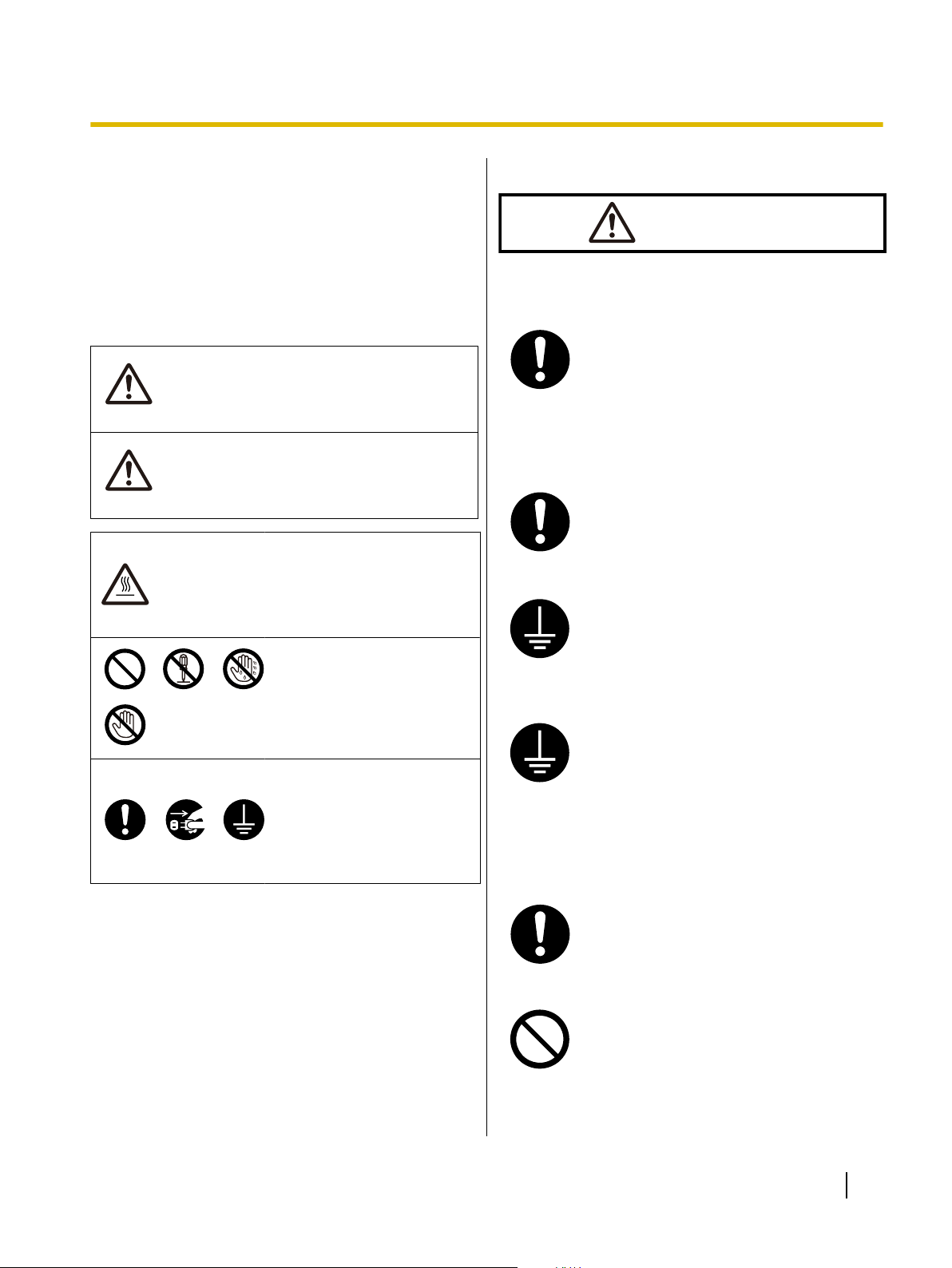
For Your Safety
To prevent severe injury and loss of life, read this
section carefully before using the unit to ensure proper
and safe operation of your unit.
• This section explains the graphic symbols used in
this manual.
Denotes a potential
hazard that could
result in serious
injury or death.
Denotes hazards
that could result in
minor injury or
damage to the unit.
This symbol is used to alert
operators to a specific
operating procedure that
must be performed
carefully.
These symbols are used to
alert operators to a specific
operating procedure that
must not be performed.
These symbols are used to
alert operators to a specific
operating procedure that
must be emphasized in
order to operate the unit
safely.
For Users
Power and Ground Connection
The power source voltage of this unit is
listed on the nameplate.
Only plug the unit into an AC outlet with
the proper voltage.
If you use a cord with an unspecified
current rating, the unit or plug may emit
smoke or become hot to the touch.
When you operate this product, the
power outlet should be near the product
and easily accessible.
To ensure safe operation the power cord
supplied must be inserted into a standard
three-prong AC outlet which is effectively
grounded (earthed) through the normal
wiring.
The fact that the equipment operates
satisfactorily does not imply that the
power point is grounded (earthed) and
that the installation is completely safe.
For your safety, if in any doubt about the
effective grounding (earthing) of the
power point, consult a qualified
electrician.
If the plug cannot be inserted into the AC
outlet, contact a licensed electrician to
replace the AC outlet with a properly
grounded (earthed) one.
Do not defeat the grounding (earthing)
plug (ex. do not use a conversion plug).
Operating Instructions 7
Page 8
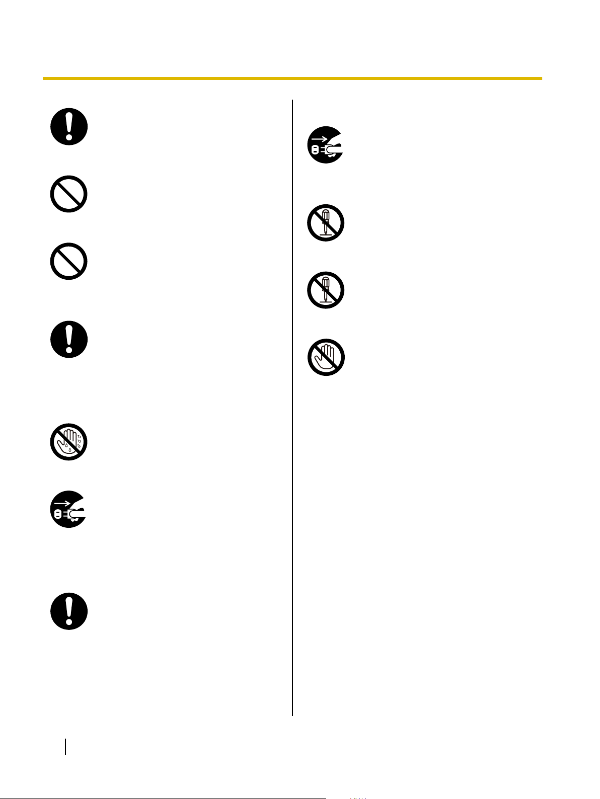
Safety Information
Plug the power cord firmly into an AC
outlet. Otherwise, it can cause fire or
electric shock.
Do not pull, bend, rest objects on, or
chafe the power cord and plug. Damage
to the power cord or plug can cause fire
or electric shock.
Do not attempt to repair the power cord,
or plug. If the power cord or plug is
damaged or frayed, contact an
authorized service representative for a
replacement.
Ensure that the plug connection is free of
dust. In a damp environment, a
contaminated connector can draw a
significant amount of current that can
generate heat, and eventually cause fire
if left unattended over an extended
period of time.
Operating Safeguards
If metal fragments or water gets into the
unit, turn the unit off and unplug the unit
immediately. Contact your dealer for
service. Operating the contaminated unit
can cause fire or electric shock.
Do not open covers, and do not attempt
to repair the unit yourself. Contact your
dealer for service.
Do not alter the unit or modify any
parts.
Alteration or modification can cause fire
or electric shock.
During thunderstorms, do not touch the
unit and plug. It may cause an electric
shock.
Never touch the plug with wet hands.
Danger of electric shock exists.
Stop operation immediately if the unit
emits smoke, excessive heat, abnormal
smell or unusual noise. These conditions
can cause fire or electric shock.
Immediately turn the unit off, and unplug
the power cord, and contact your dealer
for service.
When disconnecting the unit, grasp the
plug instead of the cord. Pulling on a cord
forcibly can damage it, and cause fire or
electric shock.
8 Operating Instructions
Page 9
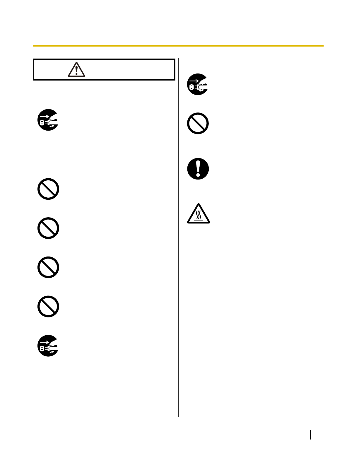
CAUTION
Power
Safety Information
Operating Safeguards
If the unit falls down or gets damaged,
turn the unit off, and unplug the power
cord. Otherwise, it may cause fire or
electric shock.
When the unit is not used over an
extended period of time, switch it off, and
unplug it. If an unused unit is left
connected to a power source for a long
period, degraded insulation may cause
electric shock, current leakage, or fire.
Installation and Relocation
Do not position the unit in a location
where it is unstable.
To prevent fire or shock hazard, do not
expose this unit to rain or any type of
moisture.
Do not place the unit in a hot humid or
dusty environment.
Prolonged exposure to these adverse
conditions may cause fire or electric
shock.
Do not place any liquids or heavy items
on the unit.
Accidental spillage of liquid into the unit
may cause severe damage. If this
occurs, turn the unit off, unplug the power
cord, and contact your dealer for service.
When the smoked plastic cover is open,
moving parts are exposed. Take care to
avoid contact with the moving parts,
including fingers, hair, jewelry, neckties,
etc. Personal injury or damage to the unit
could result.
Do not touch the printhead, as it
becomes hot, even when not printing.
Otherwise, it may cause burns.
Do not block the air vents. Doing so can
cause heat to build up, and may result in
fire.
When moving the unit, be sure to unplug
the power cord from the AC outlet. If the
unit is moved with the power cord
attached, it can cause damage to the
cord which could result in fire or electric
shock.
Operating Instructions 9
Page 10
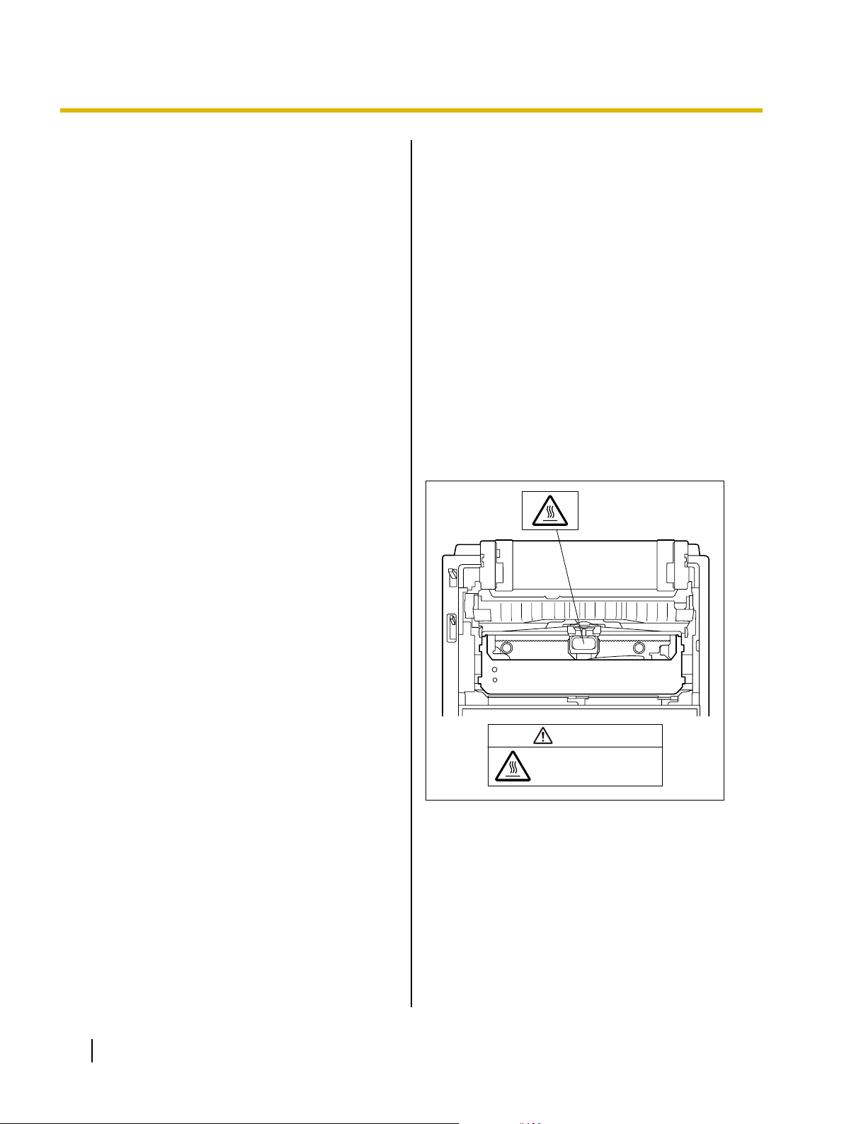
The printhead is hot.
Do not touch.
CAUTION
Safety Information
Precautions
Installation
• Do not place the unit in direct sunlight and near hot
equipment.
• The unit should not be exposed to extremely high
or low temperatures [temperature range: 10 °C to
35 °C (50 °F to 95 °F)].
• The unit should not be exposed to extremely high
or low humidity (humidity range: 30 % to 80 % RH).
• Avoid condensation resulting from rapid changes in
temperature.
• Do not place the unit in areas with poor ventilation.
• Do not place the unit in areas with high
concentrations of dust or chemical fumes, solvents,
etc.
• Do not place books, paper or other items on top of
the printer.
Operation
• Do not operate the printer without installing paper
and a ribbon cassette.
• Do not obstruct printhead movement while the
printer is operating.
• Protect the unit from static electricity.
Ink Ribbon
• Do not store the ink ribbon in direct sunlight or in a
place with a temperature over 35 °C (95 °F).
• For details about the ink ribbon, please refer to the
Material Safety Data Sheet (MSDS).
Please ask your Panasonic sales company about
obtaining the Material Safety Data Sheet.
Others
• Do not use thinner, benzine, or cleaners containing
abrasives or surfactants, for cleaning the outside of
printer.
• Plug the power cord into an outlet form which you
can easily unplug it.
Caution Labels
CD-ROM
• Do not write or stick paper on the front and/or back
of CD-ROM.
• Do not touch the data side of the CD-ROM. When
handling the CD-ROM, be careful not to leave
fingerprints or otherwise damage the CD-ROM.
• Do not leave the CD-ROM where it is directly
exposed to sunlight or near a heater for extended
periods.
• Do not throw or bend the CD-ROM.
10 Operating Instructions
Page 11
A
Before You Start
Before You Start
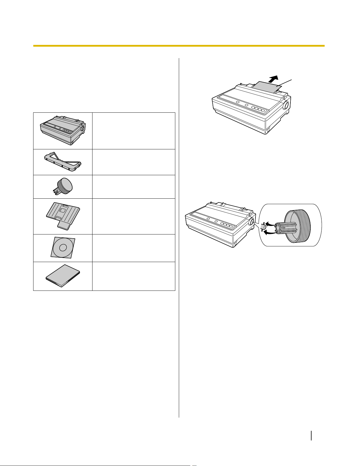
Unpacking
Having unpacked the printer, make sure none of the
contents shown below is missing or damaged.
Report damage or shortages to the store from which the
unit was purchased.
Printer (KX-P1131E)
Ribbon Cassette
Platen Knob
Extension Plate
*1
Removing the Protective Paper
A Protective paper
Installing the Platen Knob
Insert the platen knob into the hole on the right side of
the printer and rotate it slowly until it slips onto the shaft.
Push the platen knob onto the platen shaft to secure.
CD-ROM
Installation Manual
*1
Model No.: KX-P180 (USA and Canada), KX-P181 (Outside
USA and Canada)
Operating Instructions 11
Page 12
A
B
C
E
F
G
H
HEAD GAP
D
Before You Start
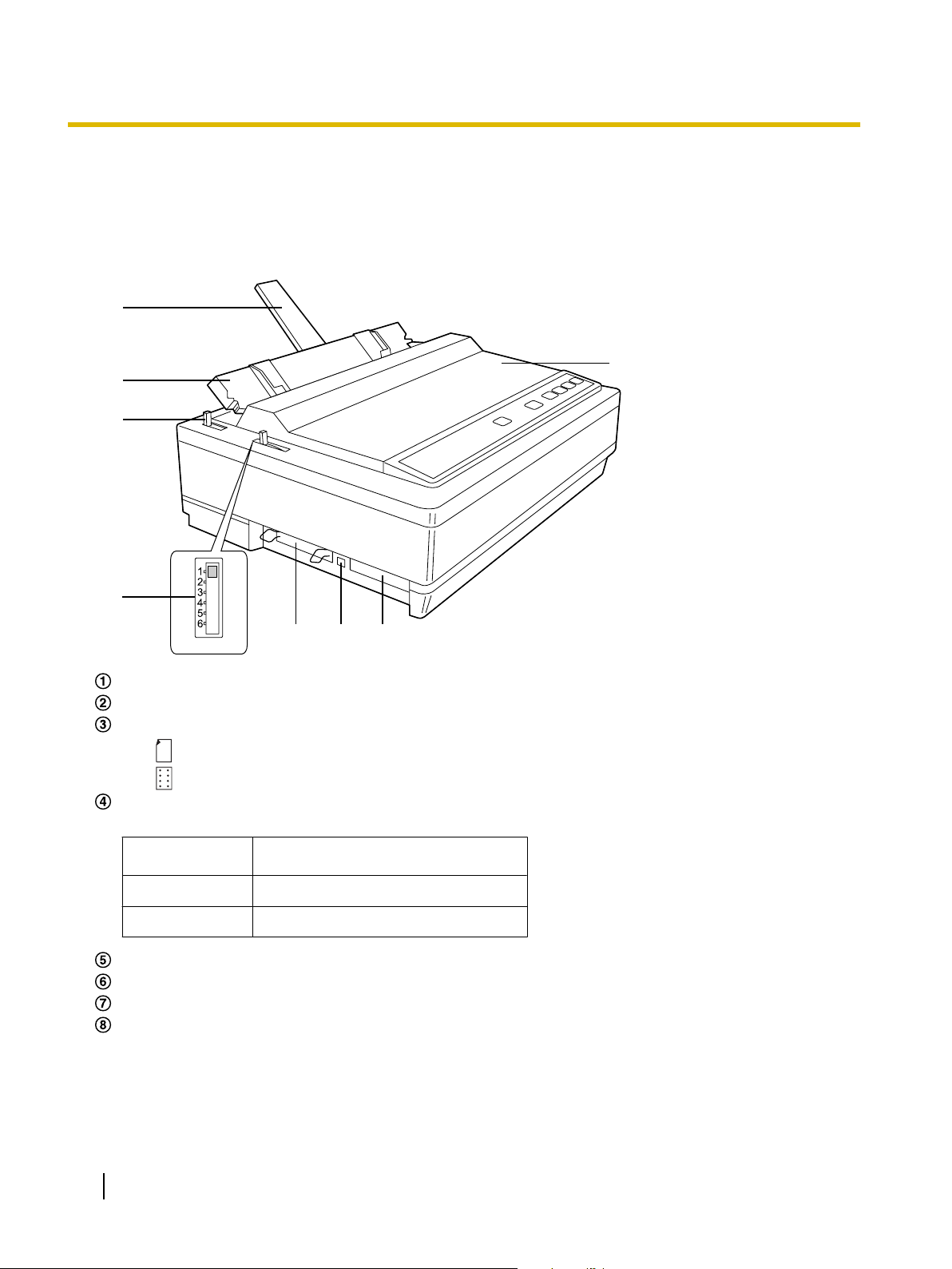
Parts of the Printer
Front View
Paper support (Page 21)
Top cover
Paper feed selector
• "
" (Friction) Single sheets and envelopes
• " " (Tractor) Fanfold paper
Head gap lever
Adjusts the gap between the platen and the printhead.
Position
1 or 2 Thinner sheets
3, 4, 5 and 6 Thick or multiple sheets, envelopes
Parallel interface connector (Page 16)
USB connector (Page 16)
Serial interface connector (Page 16)
Smoked plastic cover
Used for
12 Operating Instructions
Page 13
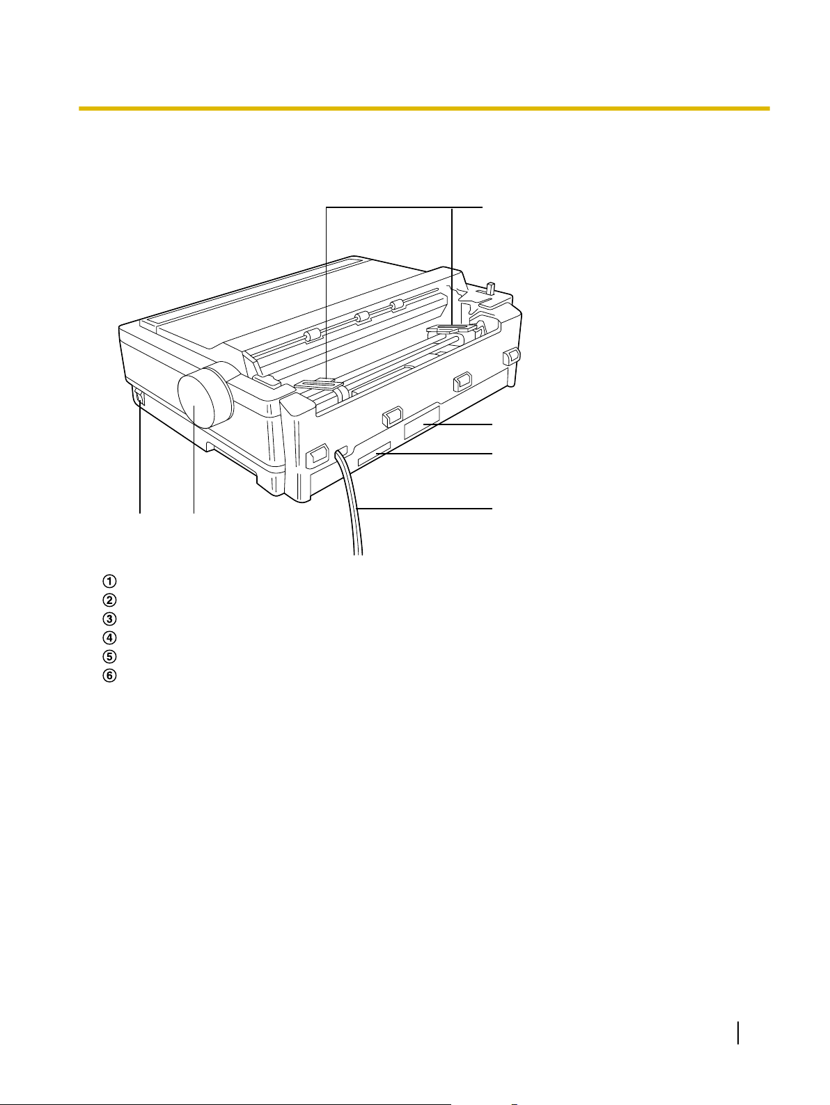
Rear View
A
BC
D
E
F
Before You Start
Tractors
Power switch (Page 17)
Platen knob (Page 11)
Power cord (Page 17)
Serial No. Label
Nameplate
Operating Instructions 13
Page 14
BACDEFGH
JK
I
Before You Start
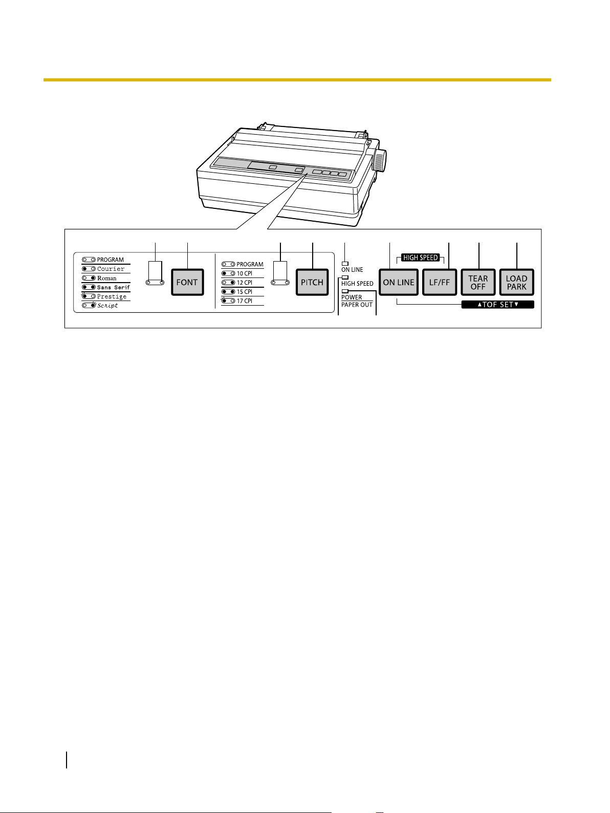
Control Panel
A FONT indicators
These indicators show the Font being selected.
(Page 28)
B FONT switch
Pressing this switch will select the character
fonts. (Page 28)
C PITCH indicators
These indicators show the current character
pitch selected.
D PITCH switch
Pressing this switch will select any one of the
character pitches.
E ON LINE indicator
This indicator is lit when the printer is in the ON
LINE mode, and is out in the OFF LINE mode.
G LF/FF switch
Pressing this switch advances the paper one
line at a time. Holding this switch advances the
paper to the first print line of the next page.
(Page 29)
H TEAR OFF switch
Pressing this switch will advance or reverse the
paper for tearing off. (Page 24)
I LOAD/PARK switch
Pressing this switch will load/park the paper.
(Page 31)
J HIGH SPEED indicator
This indicator is lit when HIGH SPEED is
activated by pressing ONLINE and LF/FF
together.
K POWER/PAPER OUT indicator
This indicator is lit when the power is on and
paper is installed. It blinks when no paper is
installed.
F ON LINE switch
This switch opens and closes the
communication line with the computer.
14 Operating Instructions
Page 15
Setup
Setup
Installing the Software
System Requirements
Computer IBM PC/AT® or compatible machine
with a CD-ROM drive
Operating
System
Interface USB 2.0 Full speed, Centronics
Software Installation
The software on the enclosed CD-ROM can be installed
on your computer.
Notice
• Make sure to install the software before
connecting your computer to the printer.
Windows 2000 / Windows XP /
Windows Vista / Windows 7
parallel (IEEE1284 standard),
RS-232C serial
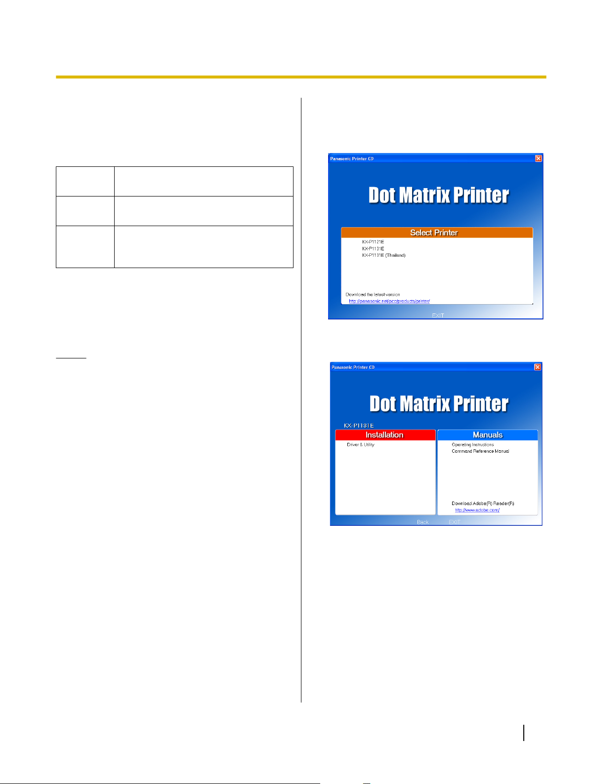
3. Select KX-P1131E (except for customers in
Thailand).
• For customers in Thailand, select KX-P1131E
(Thailand).
4. Select [Driver & Utility] from the "Installation" list on
the left side of the screen.
1. Turn on your computer and start Windows
operating system.
• Log into an account with Administrator
privileges.
2. Insert the included CD-ROM into the CD-ROM
drive.
• The setup screen will be displayed.
• If the setup screen does not appear, select your
CD-ROM drive in Explorer and double-click
[CDRun.exe].
• In Windows Vista and Windows 7, if the
Autoplay dialog box is displayed, click [Run
CDRun.exe].
5. Follow the instructions on the screen.
• In Windows Vista and Windows 7, if a window
appears with the message "Windows can't
verify the publisher of this driver software",
continue with the installation by selecting
"Install this driver software anyway".
6. Connect the computer to the printer with a USB
cable, parallel cable or serial cable. (Page 16)
Once Plug and Play detects the printer and starts,
follow the operating system's on-screen
instructions.
Operating Instructions 15
Page 16

A
B
A
C
BB
B
B
A
Setup
Connecting to a Computer
Before you connect the printer for the first time,
install the USB and Printer driver on to your
computer. For more information see "Installing the
Software (Page 15)".
Note
• If you do not have a USB cable, parallel
interface cable or serial interface cable, you will
need to purchase one or contact your dealer.
1. Turn off the power switch of both the printer and
the computer.
2. Connect an interface cable.
When connecting with a USB cable:
Attach the USB cable (B) from your
computer to the USB connector (A).
Notice
• Use a shielded USB cable that is
certified with a logo by USB-IF.
Notice
• Use a shielded parallel cable 1.95 m
(6 ft. 5 in.) or less in length. An IEEE
1284-compatible parallel cable is
recommended.
When connecting with a serial interface cable:
Attach the serial interface cable (B) from
your computer to the serial interface
connector (A) and turn the screw clockwise
to tighten.
Notice
• Use a RS-232C serial interface cable.
When connecting with a parallel interface cable:
Attach the parallel interface cable (C) from
your computer to the parallel interface
connector (A) and secure the printer clips
(B).
16 Operating Instructions
Note
• When using a serial interface cable, do
not also connect a USB cable. You
cannot print using a serial interface if a
USB cable is also connected.
Page 17

Power Supply
AC
Outlet
1. Connect the power cord to a grounded AC
outlet.
• Plug the power cord into an outlet of the proper
rating listed on the nameplate located in the rear
of the printer.
• The power switch is located on the right side of
the printer toward the front.
When the power is supplied to the printer, the
power indicator on the control panel will light up.
Setup
Note
• If the printer is not going to be used for an
extended period, unplug the power cord.
Operating Instructions 17
Page 18

A
A
B
HEAD GAP
A
A
B
Setup
Installing the Ribbon Cassette
Mounting the Ribbon Cassette
1. A Turn the power on.
B Open the smoked plastic cover (A).
2. Move the head gap lever (A) to position "6".
3. Install the ribbon cassette (B) and push down
4 arrows (A) until they click into place.
Note
• Do not take off the blue ribbon guide from
the ribbon cassette.
18 Operating Instructions
Page 19

A
ABA
B
A
B
C
B
A
HEAD GAP
Position Used for
1 or 2 Thinner sheets
3, 4, 5 and 6
Thick or multiple sheets or
envelopes
Setup
4. A Lift the blue ribbon guide (A) from the ribbon
cassette.
B Slide the blue ribbon guide between the
printhead nose (B) and the ribbon mask (C),
and push it down.
6. Close the smoked plastic cover.
7. Adjust the head gap lever for the thickness of
paper you are using.
Note
• If the ribbon cassette does not insert easily
between the printhead nose and the ribbon
mask, rotate the knob on the ribbon
cassette to reduce the slack.
5. Make sure the ribbon cassette is not twisted and
rotate the knob (A) to remove any slack.
Operating Instructions 19
Page 20

Position Used for
1 or 2 Thinner sheets
3, 4, 5 and 6
Thick or multiple sheets
A
B
HEAD GAP
A
A
A
A B
B
A
AB
B
A
B
Setup
Handling Paper
Your Panasonic printer offers two paper feed choices:
– Fanfold paper (Push tractor mode)
– Single sheets and envelopes (Friction mode)
Fanfold Paper (Push Tractor Mode)
1. A Turn the power on.
The PAPER OUT indicator will flash indicating that
no paper is installed in the printer.
B Adjust the head gap lever for the thickness
of paper you are using.
2. Set the paper feed selector (A) to the " "
position.
3. Lift off the top cover (A).
20 Operating Instructions
4. A Unlock the tractors by pulling the tractor
clamping levers (A) forward.
B Slide the tractors (B) to accommodate the
approximate width of paper being used.
Page 21

A
A
B
C
B
B
A
A
B
B
A
A
A
B
LOAD/PARK
A
A
Setup
5. Raise the tractor covers (A).
6. Place the paper with the printed side face down
and align the paper sprocket holes (B) with the
tractor pins (C), then close the tractor cover
(A).
8.
Press
.
This will load the paper to the first print line.
9. Raise the top cover (A).
This is done by inserting the side pins of the top
cover into the slots in the upper cabinet.
10. Raise the paper support (A).
7. A Adjust the tractors (A) to remove any slack.
B Lock the tractor clamping levers (B).
Note
• Make sure the paper is straight.
Operating Instructions 21
Page 22

A
ON LINE
Position Used for
1 or 2 Thinner sheets
3, 4, 5 and 6
Thick sheets or envelopes
A
B
HEAD GAP
A
Setup
11. Insert the paper support into the slot of the
extension plate (A) until it stops.
12. If the ON LINE indicator is not lit, press
to get ready to print.
Single Sheets and Envelopes (Friction Mode)
1. A Turn the power on.
The PAPER OUT indicator will flash indicating that
no paper is installed in the printer.
B Adjust the head gap lever for the thickness
of paper you are using.
22 Operating Instructions
2. Set the paper feed selector (A) to the " "
position.
Page 23

A
A
B
A
A
LOAD/PARK
ON LINE
Setup
3. Raise the top cover (A).
This is done by inserting the side pins of the top
cover into the slots in the upper cabinet.
4. Raise the paper support (A).
Note
• lf the extension plate is already installed
(Page 22), it does not need to be removed.
5. A Separate the paper guides to the approximate
width of your paper or envelope.
Note
• To predetermine your left most print
position, move the left paper guide until it
clicks into place.
B Insert a sheet of paper through the paper
guides (A).
The paper will be automatically loaded to the first
print line.
Note
• You can disable Auto load through the
Control Panel Software program
(Page 25) or by using the Control Panel
(Page 33).
• If Auto load is disabled, you must press
to load paper.
• If you need to align the paper horizontally or
vertically, set the paper feed selector to
" ". This releases the paper and allows the
paper to be positioned manually as
required. Set the selector back to " "
before printing.
6. If the ON LINE indicator is not lit, press
to get ready to print.
Operating Instructions 23
Page 24

TEAR OFF
TEAR OFF
TEAR OFF
TEAR OFF
LF/FF
Setup
Tearing off Paper
With fanfold paper installed, this function allows you to
advance your paper to the tear position. After tearing off
the page you can return your paper to the first printer
line by pressing
If
printer will automatically reverse to the first print line
upon receiving data from the computer.
is not pressed a second time, the
1. Press
the tear position.
2. Tear off the page.
again.
to advance the paper to
Self Test
The printer has a self test feature which allows you to
test the printer. When activated, this feature will print 5
lines of each resident font. When complete, it will return
to the draft font and continue for approximately 20
minutes.
1. Install the ribbon cassette and paper, then turn
the power off (Page 18–24).
2. While pressing
release.
turn the power on, then
3. Press
to the first print line.
A sample printout will begin, which serves as a self
test.
to reverse the paper back
3. Once you see that the printer is functioning
properly, you may turn the power off during the
self test, or you may run the entire test.
24 Operating Instructions
Page 25

Using the Software
Using the Software
Control Panel Software Program
This software is used to change the configuration of the
printer. Using this software, you can also print out the
printer's character table.
It is necessary to install the printer driver to use this
software.
When using the Windows driver, these settings are
rarely used.
When using the Windows driver, make sure Emulation
is set to "EPSON".
The printer is compatible with most popular software
packages. If no changes are required, you should be
ready to print. In most cases there will be no need to
change the initial setup items.
To start the Control Panel Software program, from
[Start], select [All programs] ® [Panasonic] ®
[Panasonic KX-P1131E] ® [Control Panel Software].
You can change the following items:
Print Style
Font
Draft, Bold PS, Courier, OCR-B, Prestige,
Roman, Sans Serif, Script, Bold PS-SC,
Courier-SC, Prestige-SC, Roman-SC, Sans
Serif-SC, Script-SC
Note
• "-SC" sequences are displayed only
when one of the following Code pages
is selected: USA, Multilingual, Portugal,
Canada-French, Norway, Turkey.
Point size
8, 10, 10.5, 12, 14, 16, 18, 20, 21, 22, 24, 26,
28, 30, 32
Note
• Displayed only when an "-SC"
sequence is selected in Font.
Emulation
Emulation
EPSON (Epson LQ-300 without color)
IBM (IBM Proprinter X24E)
Page Format
Line/in.
1, 1.5, 2, 2.5, 3, 4, 4.5, 5, 6, 7.5, 8, 9, 10, 12,
Scalable
Page length
11 in., 12 in., 14 in., 11 2/3 in.,
8 in., 8 1/2 in., 5 1/2 in., Free
Top margin
0–450 (1/180 in.)
Bottom margin
0–900 (1/180 in.)
Left margin
10 CPI or 5 CPI pitch: 0–78 characters
12 CPI or 6 CPI pitch: 0–93 characters
15 CPI or 7.5 CPI pitch: 0–117 characters
17 CPI or 8.5 CPI pitch: 0–133 characters
20 CPI pitch: 0–156 characters
Proportional pitch: 0–78 characters
Right margin
10 CPI or 5 CPI pitch: 2–80 characters
12 CPI or 6 CPI pitch: 3–96 characters
15 CPI or 7.5 CPI pitch: 3–120 characters
17 CPI or 8.5 CPI pitch: 4–136 characters
20 CPI pitch: 4–160 characters
Proportional pitch: 2–80 characters
Centering Position
10–45 characters
Pitch
10 CPI, 12 CPI, 15 CPI, 17 CPI, 20 CPI, P.S,
5 CPI, 6 CPI, 7.5 CPI, 8.5 CPI
Operating Instructions 25
Page 26

Using the Software
Print mode
Graphic direction
Bi Direction, Uni Direction
Text direction
Bi Direction, Uni Direction
Text Enhancement
Bold
On, Off
Double high
On, Off
Double strike
On, Off
Double wide
On, Off
Italics
On, Off
Outline
On, Off
Shadow
On, Off
Zero font
Normal, Pointed, Slashed
Character set
Character set
Italic
Graphic 1
Graphic 2
International character
USA, France, Germany, UK, Denmark 1,
Sweden, Italy, Spain 1, Japan, Norway,
Denmark 2, Spain 2, Latin America, Korea,
Slovenia, Legal
Code page
USA, Multilingual, Portugal, Canada-French,
Norway, Turkey, BRASCII, ABICOMP, PC855,
PC866, USSR GOST, Polish, Czech, PC852,
ISO Latin2, Hungarian, Bulgaria, ISO 8859-2
Install
A.G.M. (Alternate Graphic Mode) (IBM only)
On, Off
Auto CR (IBM only)
On (LF, VT, ESC+"J" +CR)
Off (LF, VT, ESC+"J" only)
Auto LF
On (CR+LF)
Off (CR only)
Auto load
On, Off
Paper out detect
On, Off
Tear off
Manual, Auto
Buffer control
22 KB, 8 KB, 0 KB, ALL
Auto Online
On, Off
Auto feed XT
On, Off
Serial Interface
Data length
8Bit, 7Bit
Baud rate
150, 300, 600, 1200, 2400, 4800, 9600, 19200
Parity
None, Ignore, Odd, Even
Protocol
DTR, XON/XOFF
Signal Polarity
Mark, Space
TOF Setting
Tractor
0–900 (1/180 in.)
Friction
0–900 (1/180 in.)
26 Operating Instructions
Note
• Some items can also be set through the Initial
Setup Mode (Page 33).
Page 27

Using the Software
About the buttons
Send Settings
Sends the settings to the printer.
Restore Default
Returns the settings to default.
After pressing this button, the screen to select your
country is displayed. Select your country. If your
country is not displayed here, select [Other
country].
Character Table
Prints out the character table of the built-in font in
the printer.
After pressing this button, the screen to select the
emulation and character table is displayed.
Select the desired table.
About
Displays the version of the software.
Exit
Exits the software.
Note
• The screen to select your country is only
displayed when activating the software for the
first time. When you activate the software from
the second time, the screen to select your
country is not displayed.
Viewing the Command Reference Manual
To refer to the Command Reference Manual, select
[Command Reference Manual] from the "Manuals" list
on the right side of the screen. (Page 15)
Uninstalling the Software
If you want to remove the software that is installed on
your computer, follow the procedure below to uninstall
them.
1. In Control Panel, open [Add or Remove Programs].
• In Windows 2000, select [Add/Remove
Programs], and in Windows Vista and
Windows 7, select [Uninstall a program].
2. Select [Panasonic KX-P1131 Series] to uninstall.
3. Follow the instructions on the screen.
Operating Instructions 27
Page 28

FONT
A
PITCH
A
Using the Control Panel
Using the Control Panel
Using the Control Panel
Selecting a Character Font
This printer contains resident fonts which are
accessible through the Control Panel. You can select
any one of the character fonts by pressing the FONT
switch on the Control Panel.
n Press
The combination of FONT indicators (A) indicates the
current character font selected, as shown on the Control
Panel.
PROGRAM Courier
.
Selecting a Character Pitch
This printer contains resident pitches which are
accessible through the Control Panel. You can select
any one of the character pitches by pressing the PITCH
switch on the Control Panel.
n Press
The combination of PITCH indicators (A) indicates the
current character pitch selected, as shown on the
Control Panel.
PROGRAM 10 CPI
12 CPI 15 CPI
.
Roman Sans Serif
Prestige Script
= light is lit. = light is out.
Note
= light is blinking.
• You must be in PROGRAM (both FONT
indicators are off) to allow your software to
control your font selection.
17 CPI
= light is lit. = light is out.
Note
= light is blinking.
• You must be in PROGRAM (both PITCH
indicators are off) to allow your software to
control your pitch selection.
28 Operating Instructions
Page 29

ON LINE
LF/FF
ON LINE
LF/FF
LF/FF
LF/FF
LF/FF
TEAR OFF
Using the Control Panel
High Speed Mode
The High Speed mode is a feature for doubling the print
speed only when LQ Font and one of the 120 dpi,
180 dpi or 360 dpi of 24-pin bit image are selected.
Note
• When enabled, this feature will lower the print
density.
Turning on the High Speed mode:
• While pressing
.
The HIGH SPEED indicator is on.
Turning off the High Speed mode:
• While pressing
.
The HIGH SPEED indicator is off.
, press
, press
Line Feed/Form Feed (LF/FF Switch)
You can adjust the paper position by using the front
panel switches when the printer is in the OFF LINE
mode or when the printer is not printing in the ON LINE
mode.
• With paper installed, pressing
advances the paper one line.
• With paper installed, holding
the printhead to the center and advances the
paper to the top of the next page.
Note
• When pressing
which is fed is determined by the current setting
for lines per inch as specified through the
Control Panel Software program, Control Panel
(Initial Setup mode) or your application
software.
, the amount of paper
once
moves
Tear Off (TEAR OFF Switch)
Pressing the
fanfold paper’s perforation to the tear position, and
pressing this switch again returns your paper to the first
print line.
switch advances your
Operating Instructions 29
Page 30

ON LINE
TEAR OFF
ON LINE
LOAD/PARK
Using the Control Panel
Top of Form Function (TOF SET)
This printer has a Top of Form (TOF) function which
stores the first print line position and loads the paper to
the designated position automatically. The first print line
position will be stored even after the power is turned off.
You can adjust the Top of Form position through the
Control Panel Software program (Page 25), or using
Micro Line Feed or Reverse Micro Line Feed from the
Control Panel within 125 mm (5 in.) from the top of your
paper.
Note
• Do not rotate the platen knob, otherwise the
printer will not be able to count the number of
lines properly.
• All adjustments must be made on the first sheet.
If you decide to change the setting and save it,
remove the paper from the tractors, then reset
and reload the paper.
1. If necessary, redefine the page length of the
paper you are using through the Control Panel
Software program (Page 25), Control Panel
(Page 28) or your application software.
Reverse Micro Line Feed:
While pressing
.
This reverses the paper one micro line [0.14 mm
(1/180 in.)]. The printer cannot reverse the paper
past the printable area (Page 44).
, press
3. At your desired position within 125 mm (5 in.)
from the top of your paper, release the switches.
The paper position will be stored automatically as
the new Top of Form position.
2. Micro Line Feed:
While pressing
This advances the paper one micro line
[0.14 mm (1/180 in.)].
, press
.
30 Operating Instructions
Page 31

LOAD/PARK
A
B
LOAD/PARK
Using the Control Panel
Paper Parking (LOAD/PARK Switch)
This function moves the fanfold paper to the park
position, enabling you to use single sheets or envelopes
without removing or wasting your fanfold paper.
1. Tear off the printed page(s) of the fanfold paper
being used (Page 24).
2. Press
paper to the park position.
3. A Move the paper feed selector to " " (Friction
Mode).
B Load single sheets or envelopes.
to reverse the fanfold
4. Move the paper feed selector to
" " (Tractor Mode).
5. Press
paper to the first print line.
to reload the fanfold
When you have finished printing, remove the sheet
(or envelope) from the printer.
Operating Instructions 31
Page 32

ON LINE
ON LINE
Using the Control Panel
Paper Out Detector
Your printer has a paper out detector. When an out of
paper condition occurs, printing stops, the printer goes
to the OFF LINE mode, and the POWER/PAPER OUT
indicator starts blinking. To continue printing to the end
of the current page, follow the steps below.
1. Press
completed.
2. Insert the new paper (Page 20).
3. If the ON LINE indicator is not lit, press
.
Note
• When Paper out detect is set to ON
(Page 34), printing stops at 1.26 mm (0.5 in.)
from the bottom of the paper.
• The paper out detector can be disabled through
the Control Panel Software program (Page 25).
repeatedly until the page is
32 Operating Instructions
Page 33

LOAD/PARK
FONT
ON LINE
FONT
ON LINE
A
B
PITCH
PITCH
LOAD/PARK
LOAD/PARK
TEAR OFF
LOAD/PARK
Using the Control Panel
Initial Setup Mode
The 18 features (items) can be set in the Initial Setup
mode through the Control Panel. For the features and
the indicators condition, refer to Page 34. These
features can also be set through the Control Panel
Software program (Page 25).
1. Load a sheet of paper (Page 20), and turn the
power off.
2. While pressing
power on to enter the Initial Setup mode.
Both FONT indicators and the HIGH SPEED
indicator will be blinking. The current settings will be
printed automatically.
, turn the
4. Press
The item’s status will change each time you press
(Page 34). To change additional
settings, repeat step 3 and 4.
5. Press
mode.
The FONT indicators will go off and the current
conditions will print.
to set the item’s status.
to exit the Initial Setup
3. Press
item.
Each time you press
you will advance to the next item. Select an item and
confirm the selection with the FONT indicators (A)
and ON LINE indicator (B) (on, off, blinking)
(Page 34).
and
to select the
and
Note
• To return all current settings to the factory
settings, follow the steps below.
,
1. While pressing
the power on, then release.
2. Press
3. Press
Initial Setup mode.
.
to exit the
, turn
Operating Instructions 33
Page 34

A
B
C
FONT
PITCH
ON LINE
Using the Control Panel
Control Panel
A FONT indicators:
Press
Item Setting
Emulation
G.direction Bi Uni — — — —
Tear off
Page length
Line/in.
Font
Pitch
Auto LF
.
C A B
B PITCH indicators:
Press
EPSON IBM — — — —
Manual Auto — — — —
11 in. 12 in. 11.66 in. 14 in. 8 in. 8.5 in.
6 LPI 8 LPI 3 LPI 4 LPI 7.5 LPI 12 LPI
Draft Courier Roman Sans Serif Prestige Script
10 CPI 12 CPI 15 CPI 17 CPI 20 CPI P.S
Off On — — — —
.
C ON LINE indicator:
Press
.
34 Operating Instructions
Page 35

Item Setting
Using the Control Panel
A.G.M.
(IBM only)
Auto CR
(IBM only)
Auto load
Paper out
detect
Auto Online
Buffer
control
Zero font
Character
set
International
character
*2
Code page
Off On — — — —
Off On — — — —
Off On — — — —
Off On — — — —
Off On — — — —
22 KB 8 KB 0 KB ALL
*1
— —
Normal Pointed Slashed — — —
Italic Graphic 1 Graphic 2 — — —
USA France Germany UK Denmark 1 Sweden
Italy Spain 1 Japan Norway Denmark 2 Spain 2
Latin
America
*2
USA Multilingual Portugal
Korea Slovenia Legal — —
Canada-
French
Norway Turkey
BRASCII ABICOMP PC855 PC866 USSRGOST Polish
Czech PC852 ISO Latin2 Hungarian Bulgaria ISO 8859-2
Indicators condition:
= light is lit. , = light is out. , = light is blinking.
,
*1
Download font function is disabled when ALL is selected.
*2
lf the current International character/Code page setting is located under the other condition of FONT indicators, the both PITCH
indicator will blink.
Operating Instructions 35
Page 36

PITCH
FONT
FONT
PITCH
PITCH
FONT
PITCH
LOAD/PARK
LOAD/PARK
TEAR OFF
LOAD/PARK
Using the Control Panel
Serial Interface Setup Mode
The following items can be set in the Interface Setup mode through the Control Panel: Data length, Baud rate,
Parity, Protocol and Signal polarity.
You can select and change the desired item according to the status of the FONT/PITCH indicators.
1. Load a sheet of paper (Page 20), and turn the power off.
2. While pressing
Both FONT indicators and the HIGH SPEED indicator will be blinking. The current settings will be printed
automatically.
3. Press
to select the item.
, turn the power on to enter the Interface Setup mode.
Each time you press
status of the FONT indicators (on, off, blinking).
4. Press
The item's status will change each time you press
To change additional settings, repeat steps 3 and 4.
A FONT indicators:
Press
Item Setting
Data length
Baud rate
Parity
Protocol
Signal Polarity
to set the item's status.
.
A
, you will advance to the next item. Select the desired item according to the
B PITCH indicators:
Press
8Bit 7Bit — — — — —
300 600 1200 2400 4800 9600 19200
None Ignore Odd Even — — —
DTR XON/XOFF — — — — —
Mark Space — — — — —
. See the table below to verify desired status.
.
B
5. Press
36 Operating Instructions
FONT/PITCH indicators condition:
= light is lit. = light is out. = light is blinking.
to exit the Interface Setup mode.
The FONT indicators will go off and the current conditions will print.
Note
• To return all current settings to the factory settings, follow the steps below.
1. While pressing
2. Press
3. Press
.
to exit the Initial Setup mode.
, turn the power on, then release.
Page 37

ON LINE
LOAD/PARK
ON LINE
PITCH
Using the Control Panel
Resetting All Current Settings to the Factory Settings
Follow the instructions below:
1. Turn the power on while pressing the
and
.
Printing Out the Current Settings
Follow the instructions below to get a print out of the
current settings.
1. Load a sheet of paper, and turn the power off.
(Page 20)
2. Turn the power on while pressing the
and
.
Operating Instructions 37
Page 38

Maintenance & Troubleshooting
M
a
i
n
Periodic Maintenance
t
e
n
a
n
c
e
&
T
r
o
u
b
l
e
s
h
o
o
t
i
n
g
The printer does not require any routine maintenance. However, reasonable care of the printer will extend its
life. The following periodic measures are recommended:
• Cleaning the unit is the most important action the user can perform.
The frequency of cleaning is dependent upon the environment.
– Turn the power off and unplug the AC power cord.
– Clean the case and covers with a soft cloth. Use any mild commercial cleaner on the cloth, do not spray
directly on the printer.
– Raise the top cover and pull up the roller cover. Vacuum or dust the inside area of the unit. Be very
careful not to damage the printhead ribbon cable or the carriage drive belt.
CAUTION
• The printhead may be hot, use caution when the cover is open.
– The platen should be cleaned with denatured alcohol only.
– The carriage guide bar can be lubricated with a very light oil. Contact your Authorized Panasonic
Service Center for advice on lubrication.
Ribbon Cassette
Note
• If the ribbon cassette begins to catch, snag, or tear from the printhead, your printer requires servicing.
38 Operating Instructions
Page 39

Maintenance & Troubleshooting
Troubleshooting
Most problems associated with the printer can be traced to improper setup, installation, or cabling.
The following table will assist the user in identifying and correcting some of the more common problems. If you
need additional help, contact the store from which the unit was purchased or the Panasonic technical support
number found in Page 4.
Symptom Possible Cause Probable Solution
Ink smears. Head gap lever is not in the
proper position.
Printout is faint. Head gap lever is not in the
proper position.
Printhead moves but there is no
printing.
Paper out detector inoperative. Paper out detect is OFF. Set Paper out detect to ON.
Printer does not power up. No AC power. Check AC power cord.
Power is on but printer does not
print.
Ribbon cassette is not installed
correctly.
Head gap lever is not in the
proper position.
Printer is not ON LINE. Press ON LINE switch.
Interface cable is not properly
connected.
Out of paper. Install new paper. (Page 20)
Printhead has become
overheated.
Move the lever toward the position
"6" until ink does not smear.
(Page 18)
Set the lever to the proper position.
(Page 12)
Re-insert ribbon cassette.
(Page 18)
Set the lever to the proper position.
(Page 12)
(Page 25, 32)
(Page 17)
Secure connection.
(Page 16)
Allow the printhead some time to
cool down. The printer will
automatically resume printing.
Carriage stops moving, all
indicators start blinking.
Paper wrinkles when using
tractor feed.
Printer cannot load single sheet
through the top.
Unexpected characters appear
in printing.
Path of printhead is blocked. Clear the path, turn the power off,
then back on to resume printing.
No reverse tension on paper. Set paper supply lower than
printer.
Paper feed selector is set to
" ".
Emulation is set incorrectly. Check printer driver of your
Set paper feed selector to " ".
software package and set
emulation accordingly.
(Page 25, Page 28)
Operating Instructions 39
Page 40

Maintenance & Troubleshooting
Symptom Possible Cause Probable Solution
Fanfold paper is jamming. Paper is not installed correctly in
tractor.
Set paper feed selector to " " and
rotate platen knob to remove
jammed paper. Reinstall paper
correctly into tractor. (Page 20)
Printout is double-spaced. Auto LF is ON. Set Auto LF to OFF.
(Page 28)
Keeps printing on the same line. Computer is not sending a LF
command.
Wrong Character Set prints. Wrong Character Set is
selected.
The FONT indicator is blinking,
or the FONT and PITCH
There is an electrical
malfunction.
Set Auto LF to ON.
(Page 28)
Set the Character Set as required.
(Page 25)
Consult your dealer.
indicators are blinking just after
turning on the power.
Cannot print ASCII characters
with code above 127.
When using a serial interface,
the printer does not print or data
loss occurs.
Data length is set incorrectly. Set Data length as required.
(Page 25, 36)
Baud rate, Parity, Protocol or
Data length does not match with
the computer.
Set Baud rate, Parity, Protocol and
Data length to match the computer.
(Page 25, 36)
A USB cable is connected. When a USB cable is connected,
the serial interface does not
operate. Disconnect the USB
cable. (Page 16)
When printing is completed,
paper is not advanced
automatically.
When printing on custom fanfold
paper, the print position shifts
after the second page.
40 Operating Instructions
Tear off, Page length, Top
margin and Bottom margin are
set incorrectly.
The created custom paper size
(paper length) setting is
incorrect.
Set Tear off to Auto and set Page
length, Top margin and Bottom
margin to meet your software
package. (Page 25)
When creating a custom size,
select "English" for Units and input
the size in inches. Round the value
to 2 decimal places, as in the
examples below:
Form size Input size
8 1/2 inch 8.50 inch
11 1/3 inch 11.34 inch
Page 41

A
p
p
e
n
d
i
x
Printer Specifications
Power requirements:
Frequency:
Refer to the nameplate located on the rear of the printer.
Current:
Interface: USB 2.0 Full speed, Centronics parallel (IEEE1284 standard),
RS-232C Serial interface
Print fonts: 3 Draft (Pica, Elite, Micron)
7 Letter Quality (Courier, Bold PS, Prestige, Script, Sans Serif,
Roman, OCR-B)
6 Scalable Fonts*1 (Courier, Bold PS, Prestige, Script, Sans Serif, Roman)
Software emulation: Epson LQ-300 without color
IBM Proprinter X24E
Buffer: Selectable
[0 KB / 8 KB / 22 KB (default) / All (54 KB max.)]
Character sets: EPSON mode ONE Italic and 18 characters set tables
15 International characters and Legal set
IBM mode 18 character set tables
Appendix
Dot configuration: 0.2 mm (1/127 in.) dot diameter
Draft LQ
Matrix
(Hor. ´ Ver.) 9 ´ 24 30 ´ 24
Dot pitch (Hor.) 0.21 mm
(1/120 in.)
(Ver.) 0.14 mm
(1/180 in.)
Maximum number of
characters per line (cpl):
Pica [10 cpi (characters per in.)] 80 cpl
Elite (12 cpi) 96 cpl
Micron (15 cpi) 120 cpl
Compressed (17 cpi) 137 cpl
Elite compressed (20 cpi) 160 cpl
Printing speed [characters
per second (cps)]:
Draft 300 cps 240 cps 200 cps
Micron Elite Pica
Letter Quality 100 cps 80 cps 66 cps
Printing direction: Uni-directional / Bi-directional (user selectable)
Line feed time: Approx. 65 ms
[with 4.2 mm (1/6 in.) line feeding]
0.07 mm
(1/360 in.)
0.14 mm
(1/180 in.)
Operating Instructions 41
Page 42

Appendix
Paper Feed: Push Tractor feed (with fanfold paper)
Friction feed (with single sheets or envelopes)
Operating environment: Temperature: 10 °C–35 °C (50 °F–95 °F)
Humidity: 30–80 % RH (Please allow the printer to stabilize at room
temperature within the operating temperature range before operation.)
Power consumption: Max: 180 W
Ready: 3 W
Self Test: 55 W
Storage environment: Temperature: -20 °C–60 °C (-4 °F–140 °F)
Humidity: 10–90 % RH
Head service life: Approx. 200 million strokes in draft mode
Ribbon cassette: Black fabric ribbon in cassette
Life expectancy in Draft mode: Approx. 6 million characters
Detectors: Paper out detector
Printhead overheat detector
Overload detector
Dimensions:
(Width ´ Depth ´ Height)
434 ´ 326 ´ 140 mm
(17.1 ´ 12.8 ´ 5.5 in.)
Mass (Weight): Approx. 5.4 kg (12 lbs)
*1
Scalable Fonts are available only when one of the following Code pages is selected: USA, Multilingual, Portugal, Canada French,
Norway, Turkey.
42 Operating Instructions
Page 43

Paper Specifications
Paper which may be used with this unit must be within the specifications provided below.
Fanfold Paper
Width: 102–254 mm (4–10 in.)
Quality and number of sheets:
Weight
Type of paper
Fine-quality paper 1 16–24 60–90
Non-carbon 2–5 11–14 (17*1) 41–53 (64*1)
Multi-layered with carbon 2 11–14 (17*1) 41–53 (64*1)
*1
Only for the last sheet
Note
• To insure optimum print quality, 60–82.5 g/m² (16–22 lbs.) is recommended for graphic printing.
• In multi-layered paper with carbon, the carbon is equivalent to a sheet of paper.
• "Weight in pounds" represents the weight of 500 [423 ´ 559 mm (17 ´ 22 in.)] sheets.
• The printer will handle multipart forms up to 0.36 mm (0.014 in.) thick. Up to 5 copies of 14 lbs. chemical
release paper can be used.
Sheets
in lbs in g/m²
Appendix
Single Sheets
Width: 102–297 mm (4–11.7 in.)
Height: 127–363 mm (5–14.3 in.)
Weight in pounds (g/m²): 53–90 g/m² (14–24 lbs)
Note
• Paper should be within operating temperature and humidity ranges at least 24 hours prior to use.
• Due to letter head varying in paper weight and construction, we cannot guarantee print quality and
paper handling for all types.
Envelopes
#6 and #10 size envelopes are recommended. Since envelopes vary in size, paper weight and construction,
we cannot guarantee print quality and paper handling for all types of envelopes.
Note
• To optimize print quality printing should not occur in areas where the edges overlap.
Operating Instructions 43
Page 44

1st character
Paper perforations
Printing area
Printing area
A
D
B
A
C
Appendix
Printing Area
Fanfold Paper
B. The minimum distance between the sprockets and first printable character. (When the left tractor is
A. The area near the paper perforations where the print quality may not be optimum.
C. The area from the top edge of the paper to the top of the first printed character.
D. The area from the bottom edge of the paper where the print quality may not be optimum.
Fanfold Paper
A 25.4 mm (1 in.)
B 17.8 mm (0.7 in.)
C 2 mm (0.08 in.)
D 15 mm (0.6 in.)
set on the left end and the margin is set to 0.)
44 Operating Instructions
Page 45

Single Sheets and Envelopes
B
D
C
1st character
Printing area
Single Sheets and Envelopes
B 3 mm (0.12 in.)
Appendix
C 2 mm (0.08 in.)
D 15 mm (0.6 in.)
B. The minimum distance between the edge of the paper and first printable character. (When the left
paper guide is set to the 0 position and the margin is set to 0.)
C. The area from the top edge of the paper to the top of the first printed character.
D. The position where paper out is detected and printing may not be optimum. (When printing on
envelopes, do not print on area where edges overlap. Print quality may not be optimum.)
Operating Instructions 45
Page 46

Appendix
Supplies
KX-P180 (USA and Canada)
KX-P181 (Outside USA and Canada)
Note
• To purchase Ribbon Cassette, please contact your dealer.
Model Number Description
Ribbon Cassette (black)
46 Operating Instructions
Page 47

Index
Index
A
Alternate Graphic Mode (A.G.M.) 26, 35
Auto CR 26, 35
Auto LF 26, 34, 40
Auto load 26, 35
Auto Online 26, 35
B
Bi direction 26
Bold PS 41
Buffer 26, 35, 41
C
CAUTION 7
CD-ROM 11
Character Per Line 41
Character set 26, 35, 41
Code page 26, 35
Connecting 16
Control Panel 14, 28, 34
Control Panel Software Program 25
Courier 41
D
Data length 26, 36
Detectors 32, 42
Overheat detector 42
Overload detector 42
Paper Out detector 42
Dot configuration 41
Dot matrix 41
E
Elite 41
Emulation 25, 34
Epson LQ-850 25
IBM Proprinter X24E 25
Extension Plate 11
F
Factory Settings 33, 36, 37
Fanfold paper 12, 20, 42
FONT indicators 14, 34
FONT switch 14
Form Feed (FF) 29
Friction 12, 22
G
Graphic direction 26, 34
H
Head gap lever 12
Head service life 42
HIGH SPEED indicator 14
High Speed mode 29
I
Initial Setup mode 33
Interface 26, 41
Italic 26
L
LF/FF switch 14
Line Feed (LF) 29
LOAD/PARK switch 14
M
Maintenance 38
Margin 25
Micro line feed 30
Micron 41
O
ON LINE indicator 14, 34
ON LINE switch 14
Operating environment 10
Overheat detector 42
Overload detector 42
P
Page format 25
Page length 25, 34
Paper 43
installation 20, 22
specifications 43
Paper Feed 42
Friction Mode 22, 42
Tractor Mode 20, 42
Paper feed selector 12
Paper out detector 42
Paper support 12
Paper thickness 12
Parallel interface cable 16
Parallel interface connector 12, 16
Parts of the Printer 12
Pica 41
Pitch 25, 28, 34, 41
PITCH indicators 14, 34
PITCH switch 14, 28
Platen knob 11, 13
Power cord 13
Power requirements 41
Power switch 13
POWER/PAPER OUT indicator 14
Operating Instructions 47
Page 48

Index
Precautions 10
Prestige 41
Print Font 41
Printer driver 16
Printing Area 44
Printing direction 41
Printing Speed 2, 41
Proportional Spacing (P.S) 34
R
Reverse micro line feed 30
Ribbon cassette 11, 18, 38
S
Self Test 24
Serial interface 26
Serial interface cable 16
Serial interface connector 12, 16
Serial Interface Setup mode 36
Single sheet 22, 43, 45
Smoked plastic cover 12
Specifications 41, 43
T
Tear off 26, 29, 34
TEAR OFF switch 14
Text direction 26
TOF Setting 26
Top cover 12
Top of Form (TOF) set 30
Tractor clamping levers 20
Tractors 13
Troubleshooting 39
U
Uni direction 26
Unpacking 11
USB cable 16
USB connector 12, 16
W
WARNING 7
Z
Zero font 26, 35
48 Operating Instructions
Page 49

PJQXC0334ZA KK0210KU0
© Panasonic System Networks Co., Ltd. 2010
Web Site: http://www.panasonic.net/
 Loading...