

Page 1
Model No.
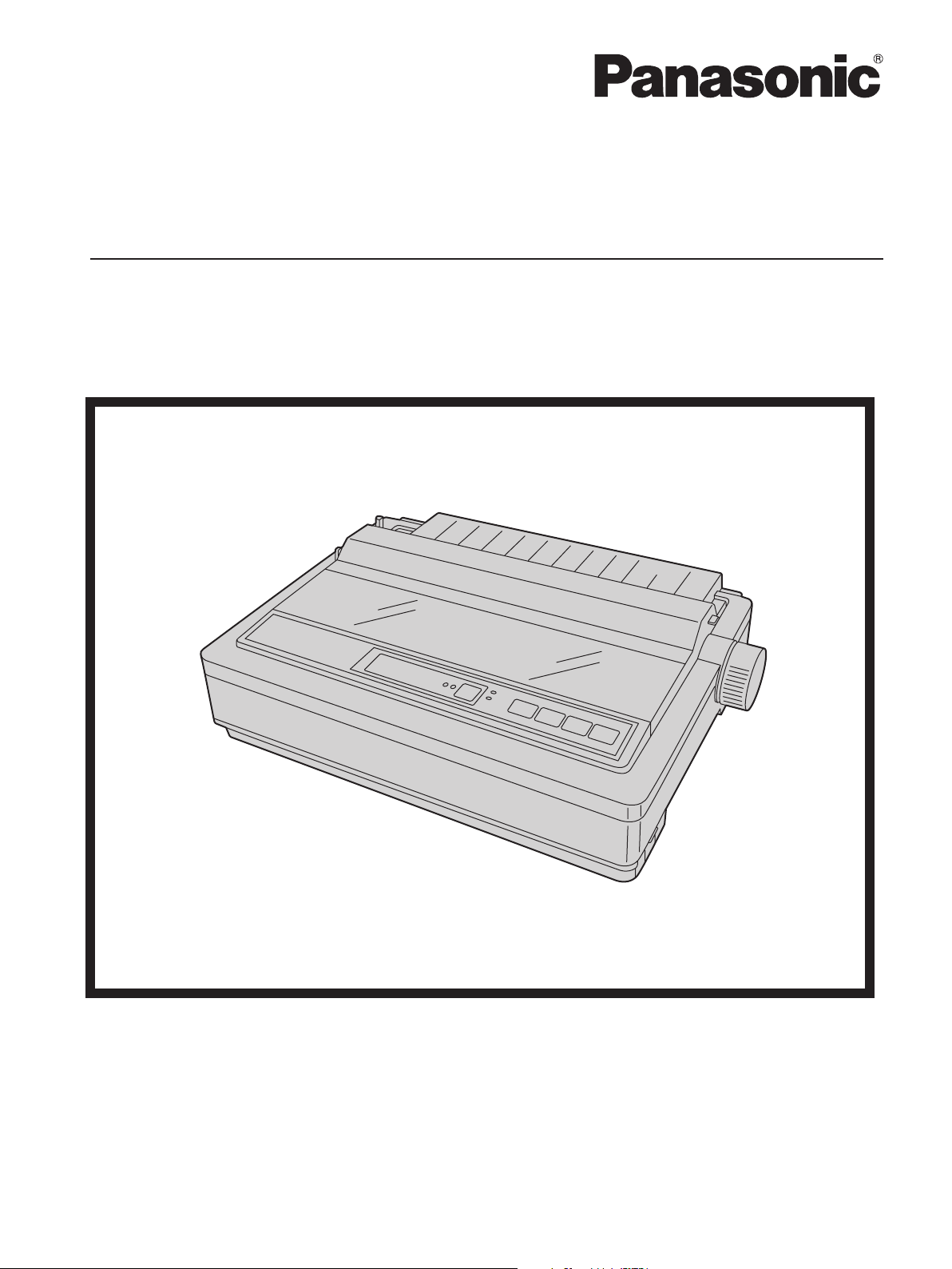
KX-P1121E
Operating Instructions
Please carefully read this manual, and keep this documentation in a safe place for future reference.
Impact Dot Matrix Printer
Page 2

Introduction
Introduction
Thank you for purchasing the Panasonic KX-P1121E Impact Dot Matrix Printer.
This printer is a versatile, high quality 24-pin dot matrix printer which is designed to meet the needs of your
office.
This printer has been factory set to operate with the most popular software packages. Your application software
should control the printer’s functions. In most cases, there will be no need to change the factory settings.
For optimum performance and safety, please read these instructions carefully.
Feature Highlights
Printer Emulation: Epson® LQ-850 and IBM® Proprinter® X24E
Font: 3 Draft (Pica, Elite, Micron)
3 LQ (Courier, Bold PS, Prestige)
Printing speed: Draft—192 characters per second (12 cpi)
LQ—64 characters per second (12 cpi)
Paper Feeding: Friction and Tractor
Tear Off: Advances fanfold paper's perforation to tear position
Paper Parking: Allows to use single sheets/envelopes without removing/wasting fanfold paper
Interface: USB 2.0 and parallel
About the documentation
The printer’s documentation consists of 2 manuals.
Operating Instructions
(this manual)
Installation Manual
(printed documentation)
The Operating Instructions explain part names, installation,
operations, maintenance and specifications of the unit.
The Installation Manual explains installation procedures.
2 Operating Instructions
Page 3

Abbreviations
As an ENERGY STAR® Partner, Panasonic has determined that this product meets
the ENERGY STAR guidelines for energy efficiency.
Windows® refers to the Microsoft® Windows® operating system.
Windows® 2000 refers to the Microsoft® Windows® 2000 operating system.
Windows® XP refers to the Microsoft® Windows® XP operating system.
Windows Vista® refers to the Microsoft® Windows Vista® operating system.
Windows® 7 refers to the Microsoft® Windows® 7 operating system.
Trademarks
• Microsoft, Windows, Windows Vista are either registered trademarks or trademarks of Microsoft
Corporation in the United States and/or other countries.
• IBM, AT and Proprinter are trademarks of International Business Machines Corporation in the United
States, other countries, or both.
• Epson is a registered trademark of Seiko Epson Corporation (SEC), registered in the U.S. and other
countries.
• All other trademarks identified herein are the property of their respective owners.
International ENERGY STAR Program
Introduction
Operating Instructions 3
Page 4

Introduction
Federal Communications Commission Requirements (For United States
only)
Note
This equipment has been tested and found to comply with the limits for a Class B digital device, pursuant
to Part 15 of the FCC Rules. These limits are designed to provide reasonable protection against harmful
interference in a residential installation.
This equipment generates, uses, and can radiate radio frequency energy and, if not installed and used in
accordance with the instructions, may cause harmful interference to radio communications.
However, there is no guarantee that interference will not occur in a particular installation. If this equipment
does cause harmful interference to radio or television reception, which can be determined by turning the
equipment off and on, the user is encouraged to try to correct the interference by one or more of the
following measures:
• Reorient or relocate the receiving antenna.
• Increase the separation between the equipment and receiver.
• Connect the equipment into an outlet on a circuit different from that to which the receiver is connected.
• Consult the dealer or an experienced radio/TV technician for help.
The user may find the booklet "Something About Interference" available from FCC local regional offices
helpful.
FCC Warning: To assure continued FCC emission limit compliance, the user must use the recommended
shielded interfacing cable when connecting to a host computer. Also, any unauthorized changes or
modifications to this equipment would void the user’s authority to operate this device.
FCC Declaration of Conformity
Trade Name: Panasonic
Model Number: KX-P1121E
Responsible Party: Panasonic Corporation of North America
One Panasonic Way
Secaucus, NJ 07094 U.S.A.
Telephone No.: 1-800-726-2797
This device complies with Part 15 of the FCC Rules.
Operation is subject to the following two conditions:
(1) This device may not cause harmful interference, and (2) this device must accept any interference
received, including interference that may cause undesired operation.
Technical Support Calls (For United States only)
If you have read this manual and tried the troubleshooting procedures and you are still having difficulty, please
contact the reseller from which the unit was purchased. You may also call the end user technical support
telephone number which is operational during East Coast business hours (9:00 AM to 7:00 PM).
The end user technical support number is 1-800-726-2797.
4 Operating Instructions
Page 5

Table of Contents
Safety Information ....................................................................................7
For Your Safety .................................................................................................................7
Safety Information (For United Kingdom only) ............................................................10
Precautions ......................................................................................................................11
Before You Start .....................................................................................12
Unpacking ........................................................................................................................12
Removing the Protective Paper ......................................................................................12
Installing the Platen Knob ...............................................................................................12
Parts of the Printer ..........................................................................................................13
Setup .......................................................................................................16
Installing the Software ....................................................................................................16
System Requirements ....................................................................................................16
Software Installation .......................................................................................................16
Connecting to a Computer .............................................................................................17
Power Supply .................................................................................................................17
Installing the Ribbon Cassette .......................................................................................18
Mounting the Ribbon Cassette .......................................................................................18
Removing the Ribbon Cassette ......................................................................................20
Handling Paper ................................................................................................................20
Fanfold Paper (Tractor Push Mode) ...............................................................................20
Single Sheets and Envelopes (Friction Mode) ...............................................................23
Self Test ...........................................................................................................................24
Table of Contents
Using the Software .................................................................................25
Control Panel Software Program ...................................................................................25
Viewing the Command Reference Manual ....................................................................26
Uninstalling the Software ...............................................................................................26
Using the Control Panel ........................................................................27
Using the Control Panel .................................................................................................27
Selecting a Character Font .............................................................................................31
Feeding Paper .................................................................................................................31
Line Feed/Form Feed (LF/FF Switch) ............................................................................31
Tear Off (TEAR OFF Switch) .........................................................................................31
Paper Parking (LOAD/PARK Switch) .............................................................................31
Maintenance & Troubleshooting ..........................................................32
Periodic Maintenance .....................................................................................................32
Troubleshooting ..............................................................................................................33
Appendix .................................................................................................35
Printer Specifications .....................................................................................................35
Paper Specifications .......................................................................................................37
Fanfold Paper .................................................................................................................37
Single Sheets .................................................................................................................37
Envelopes .......................................................................................................................37
Operating Instructions 5
Page 6

Table of Contents
Printing Area ...................................................................................................................38
Supplies ...........................................................................................................................40
Index..............................................................................................................41
6 Operating Instructions
Page 7
W ARNING
CAUTION
W ARNING
Safety Information
Safety Information
For Your Safety
To prevent severe injury and loss of life, read this
section carefully before using the unit to ensure proper
and safe operation of your unit.
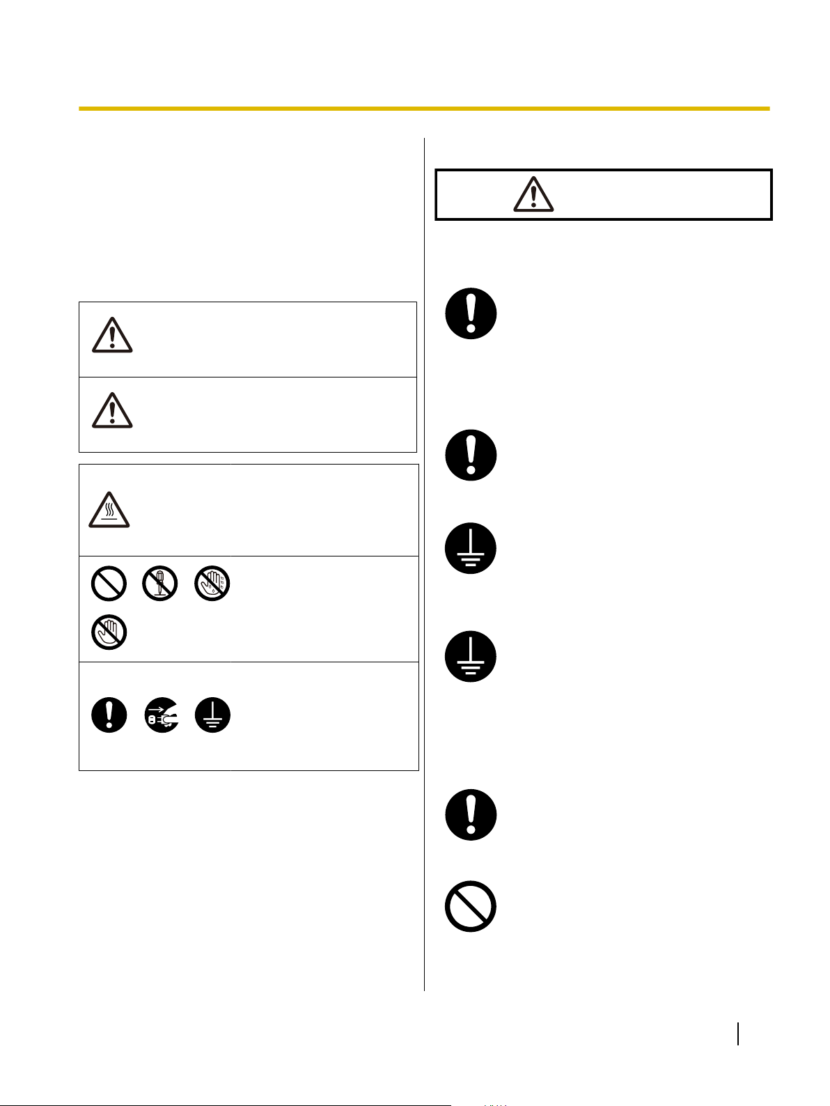
• This section explains the graphic symbols used in
this manual.
Denotes a potential
hazard that could
result in serious
injury or death.
Denotes hazards
that could result in
minor injury or
damage to the unit.
This symbol is used to alert
operators to a specific
operating procedure that
must be performed
carefully.
These symbols are used to
alert operators to a specific
operating procedure that
must not be performed.
These symbols are used to
alert operators to a specific
operating procedure that
must be emphasized in
order to operate the unit
safely.
For Users
Power and Ground Connection
The power source voltage of this unit is
listed on the nameplate.
Only plug the unit into an AC outlet with
the proper voltage.
If you use a cord with an unspecified
current rating, the unit or plug may emit
smoke or become hot to the touch.
When you operate this product, the
power outlet should be near the product
and easily accessible.
To ensure safe operation the power cord
supplied must be inserted into a standard
three-prong AC outlet which is effectively
grounded (earthed) through the normal
wiring.
The fact that the equipment operates
satisfactorily does not imply that the
power point is grounded (earthed) and
that the installation is completely safe.
For your safety, if in any doubt about the
effective grounding (earthing) of the
power point, consult a qualified
electrician.
If the plug cannot be inserted into the AC
outlet, contact a licensed electrician to
replace the AC outlet with a properly
grounded (earthed) one.
Do not defeat the grounding (earthing)
plug (ex. do not use a conversion plug).
Operating Instructions 7
Page 8
Safety Information
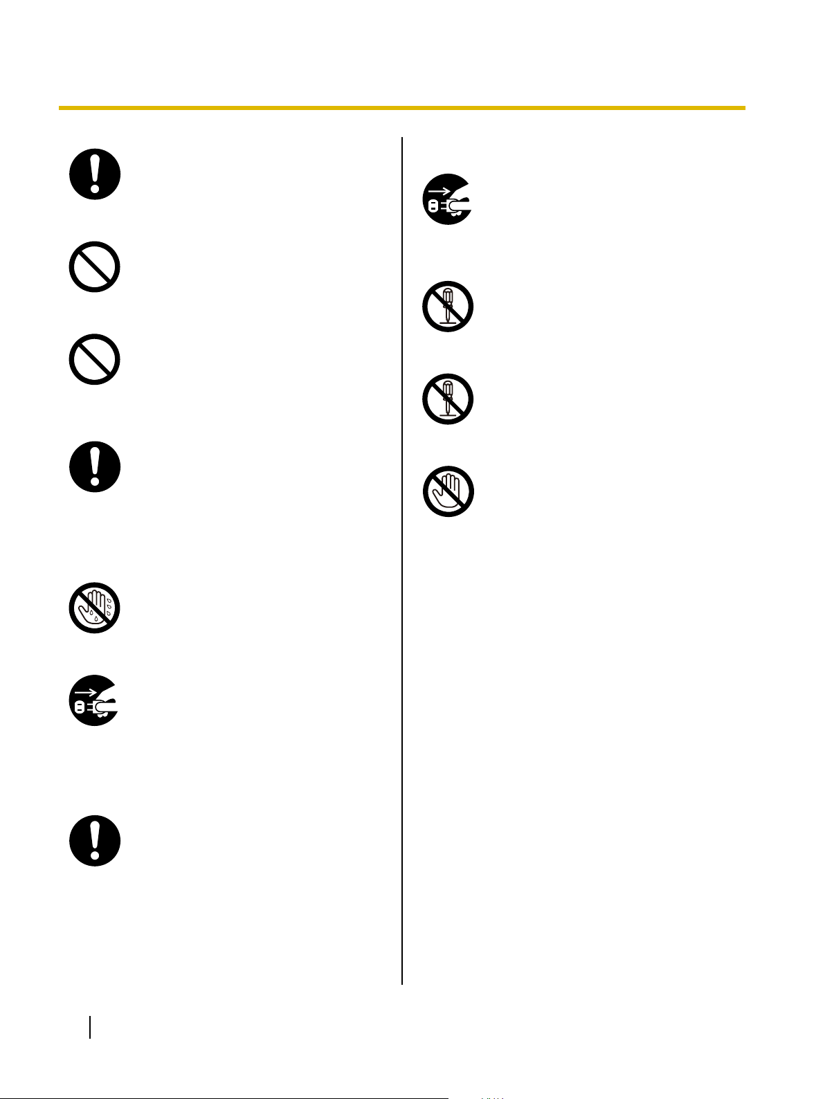
Plug the power cord firmly into an AC
outlet. Otherwise, it can cause fire or
electric shock.
Do not pull, bend, rest objects on, or
chafe the power cord and plug. Damage
to the power cord or plug can cause fire
or electric shock.
Do not attempt to repair the power cord,
or plug. If the power cord or plug is
damaged or frayed, contact an
authorized service representative for a
replacement.
Ensure that the plug connection is free of
dust. In a damp environment, a
contaminated connector can draw a
significant amount of current that can
generate heat, and eventually cause fire
if left unattended over an extended
period of time.
Operating Safeguards
If metal fragments or water gets into the
unit, turn the unit off and unplug the unit
immediately. Contact your dealer for
service. Operating the contaminated unit
can cause fire or electric shock.
Do not open covers, and do not attempt
to repair the unit yourself. Contact your
dealer for service.
Do not alter the unit or modify any
parts.
Alteration or modification can cause fire
or electric shock.
During thunderstorms, do not touch the
unit and plug. It may cause an electric
shock.
Never touch the plug with wet hands.
Danger of electric shock exists.
Stop operation immediately if the unit
emits smoke, excessive heat, abnormal
smell or unusual noise. These conditions
can cause fire or electric shock.
Immediately turn the unit off, and unplug
the power cord, and contact your dealer
for service.
When disconnecting the unit, grasp the
plug instead of the cord. Pulling on a cord
forcibly can damage it, and cause fire or
electric shock.
8 Operating Instructions
Page 9
CAUTION
Power
Safety Information
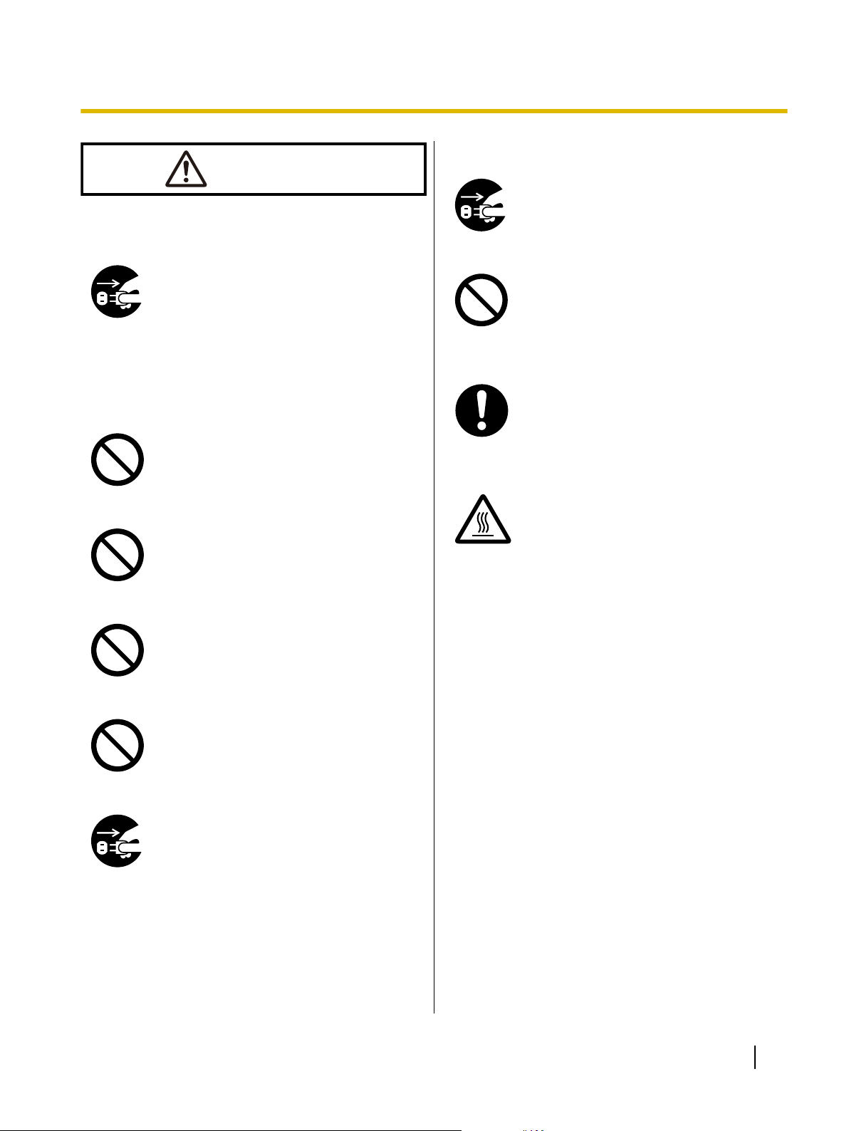
Operating Safeguards
If the unit falls down or gets damaged,
turn the unit off, and unplug the power
cord. Otherwise, it may cause fire or
electric shock.
When the unit is not used over an
extended period of time, switch it off, and
unplug it. If an unused unit is left
connected to a power source for a long
period, degraded insulation may cause
electric shock, current leakage, or fire.
Installation and Relocation
Do not position the unit in a location
where it is unstable.
To prevent fire or shock hazard, do not
expose this unit to rain or any type of
moisture.
Do not place the unit in a hot humid or
dusty environment.
Prolonged exposure to these adverse
conditions may cause fire or electric
shock.
Do not place any liquids or heavy items
on the unit.
Accidental spillage of liquid into the unit
may cause severe damage. If this
occurs, turn the unit off, unplug the power
cord, and contact your dealer for service.
When the smoked plastic cover is open,
moving parts are exposed. Take care to
avoid contact with the moving parts,
including fingers, hair, jewelry, neckties,
etc. Personal injury or damage to the unit
could result.
Do not touch the printhead, as it
becomes hot, even when not printing.
Otherwise, it may cause burns.
Do not block the air vents. Doing so can
cause heat to build up, and may result in
fire.
When moving the unit, be sure to unplug
the power cord from the AC outlet. If the
unit is moved with the power cord
attached, it can cause damage to the
cord which could result in fire or electric
shock.
Operating Instructions 9
Page 10
Safety Information
Safety Information (For United Kingdom only)
This appliance is supplied with a moulded three pin
mains plug for your safety and convenience.
A 5 amp fuse is fitted in this plug. Should the fuse need
to be replaced, please ensure that the replacement fuse
has a rating of 5 amps and that it is approved by ASTA
or BSI to BS1362. Check for the ASTA mark
BSI mark on the body of the fuse. If the plug contains
a removable fuse cover, you must ensure that it is
refitted when the fuse is replaced. If you lose the fuse
cover, the plug must not be used until a replacement
cover is obtained. A replacement fuse cover can be
purchased from your local Panasonic Dealer.
IF THE FITTED MOULDED PLUG IS UNSUITABLE
FOR THE SOCKET OUTLET IN YOUR PREMISES,
THEN THE FUSE SHOULD BE REMOVED AND THE
PLUG CUT OFF AND DISPOSED OF SAFELY.
THERE IS A DANGER OF SEVERE ELECTRICAL
SHOCK IF THE CUT OFF PLUG IS INSERTED INTO
ANY 13 AMP SOCKET.
If a new plug is to be fitted, please observe the wiring
code as shown below. If in any doubt, please consult a
qualified electrician.
or the
As the colours of the wire in the mains lead of this
apparatus may not correspond with the coloured
markings identifying the terminals in your plug,
proceed as follows.
The wire that is coloured GREEN-AND-YELLOW
must be connected to the terminal in the plug which
is marked with the letter E or by the Earth symbol
or coloured GREEN or GREEN-AND-YELLOW.
The wire that is coloured BLUE must be connected to
the terminal in the plug that is marked with the letter
N or coloured BLACK.
The wire that is coloured BROWN must be connected
to the terminal in the plug which is marked with the
letter L or coloured RED.
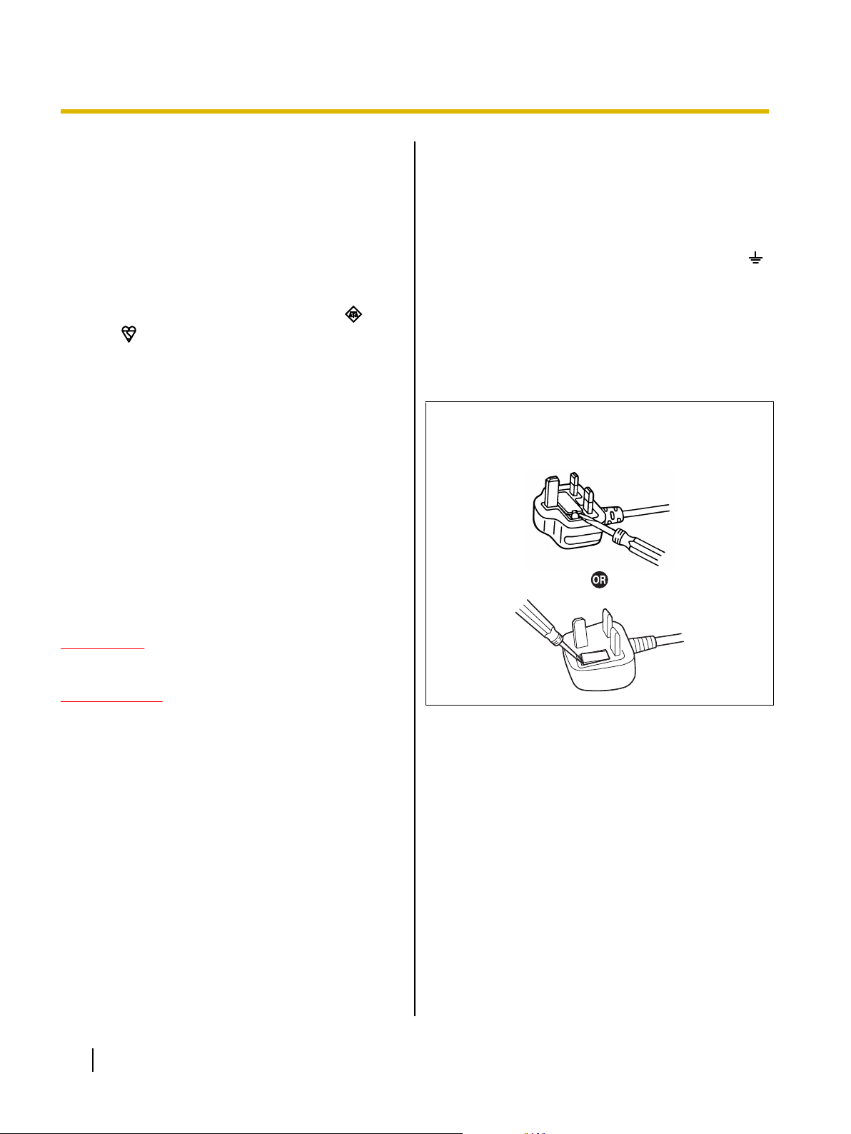
How to replace the fuse:
Open the fuse compartment with a screwdriver and
replace the fuse and fuse cover.
WARNING
This appliance must be earthed.
IMPORTANT
The wires in this mains lead are coloured as
follows:
Green-and Yellow: Earth
Blue: Neutral
Brown: Live
10 Operating Instructions
Page 11
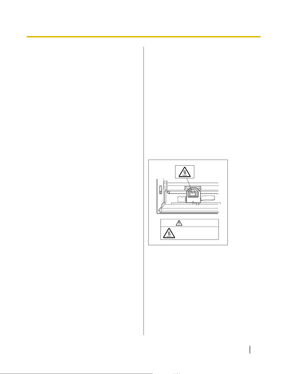
The printhead is hot.
Do not touch.
CAUTION
Safety Information
Precautions
Installation
• Do not place the unit in direct sunlight and near hot
equipment.
• The unit should not be exposed to extremely high
or low temperatures [temperature range: 5 °C to
40 °C (41 °F to 104 °F)].
• The unit should not be exposed to extremely high
or low humidity (humidity range: 20 % to 80 % RH).
• Avoid condensation resulting from rapid changes in
temperature.
• Do not place the unit in areas with poor ventilation.
• Do not place the unit in areas with high
concentrations of dust or chemical fumes, solvents,
etc.
• Do not place books, paper or other items on top of
the printer.
Operation
• Do not operate the printer without installing paper
and a ribbon cassette.
• Do not obstruct printhead movement while the
printer is operating.
• Protect the unit from static electricity.
Ink Ribbon
• Do not store the ink ribbon in direct sunlight or in a
place with a temperature over 40 °C (104 °F).
• For details about the ink ribbon, please refer to the
Material Safety Data Sheet (MSDS).
Please ask your Panasonic sales company about
obtaining the Material Safety Data Sheet.
Others
• Do not use thinner, benzine, or cleaners containing
abrasives or surfactants, for cleaning the outside of
printer.
• Plug the power cord into an outlet form which you
can easily unplug it.
Caution Labels
CD-ROM
• Do not write or stick paper on the front and/or back
of CD-ROM.
• Do not touch the data side of the CD-ROM. When
handling the CD-ROM, be careful not to leave
fingerprints or otherwise damage the CD-ROM.
• Do not leave the CD-ROM where it is directly
exposed to sunlight or near a heater for extended
periods.
• Do not throw or bend the CD-ROM.
Operating Instructions 11
Page 12
A
Before You Start
Before You Start
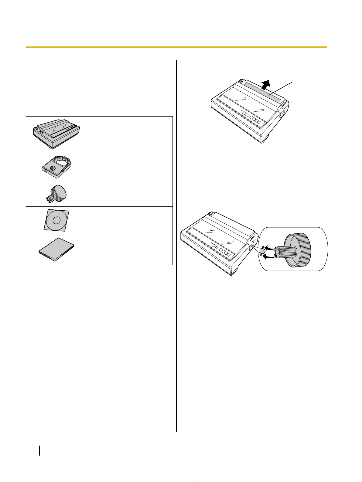
Unpacking
Having unpacked the printer, make sure none of the
contents shown below is missing or damaged.
Report damage or shortages to the store from which the
unit was purchased.
Printer (KX-P1121E)
Ribbon Cassette (KX-P145)
Platen Knob
CD-ROM
Removing the Protective Paper
A Protective paper
Installing the Platen Knob
Insert the platen knob into the hole on the right side of
the printer and rotate it slowly until it slips onto the shaft.
Push the platen knob onto the platen shaft to secure.
Installation Manual
12 Operating Instructions
Page 13
Parts of the Printer
1
2
3
4
5
6
A
B
C
D
E
F
G
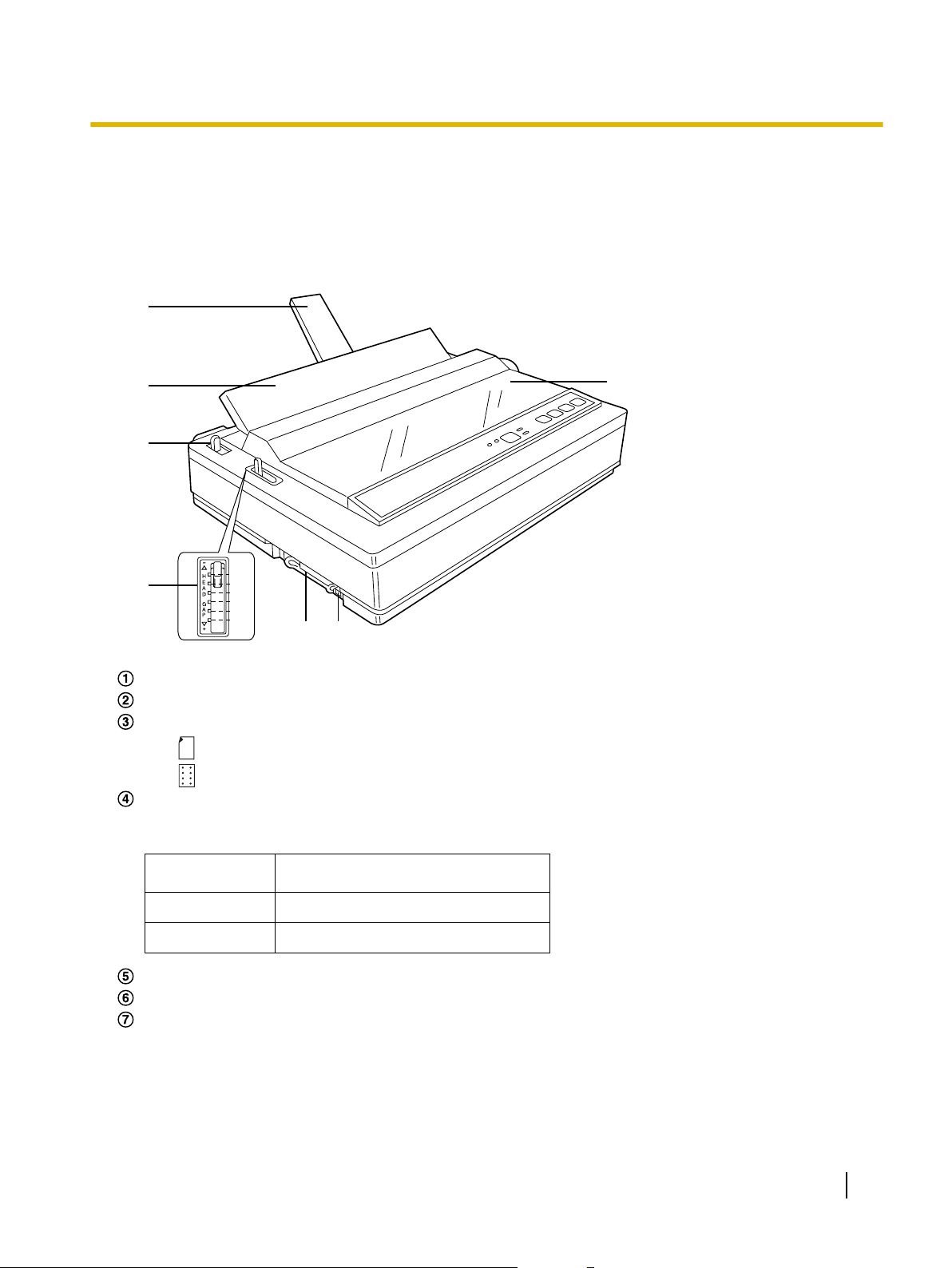
Front View
Before You Start
Paper support (Page 23)
Top cover
Paper feed selector
• " " (Friction) Single sheets and envelopes
• " " (Tractor) Fanfold paper
Head gap lever
Adjusts the gap between the platen and the printhead.
The lever moves in increments of 0.07 mm (0.0028 in.).
Position
1 or 2 Thinner sheets
3, 4, 5 and 6 Thick or multiple sheets, envelopes
Parallel interface connector (Page 17)
USB connector (Page 17)
Smoked plastic cover
Used for
Operating Instructions 13
Page 14

A
B
C
D
E
F
Before You Start
Rear View
Tractors
Power switch (Page 17)
Platen knob (Page 12)
Power cord (Page 17)
Serial No. Label
Nameplate
14 Operating Instructions
Page 15

Control Panel
AB
CDEF
GH
Before You Start
FONT switch
Pressing this switch will select the character fonts. (Page 31)
ON LINE indicator
This indicator is lit when the printer is in the ON LINE mode, and is out in the OFF LINE mode.
ON LINE switch
This switch opens and closes the communication line with the computer.
LF/FF switch
Pressing this switch advances the paper one line at a time. Holding this switch advances the paper to the
first print line of the next page. (Page 31)
TEAR OFF switch
Pressing this switch will advance or reverse the paper for tearing off. (Page 31)
LOAD/PARK switch
Pressing this switch will load/park the paper. (Page 31)
FONT indicators
These indicators show the Font being selected. (Page 31)
POWER/PAPER OUT indicator
This indicator is lit when the power is on and paper is installed. It blinks when no paper is installed.
Operating Instructions 15
Page 16

Setup
Setup
Installing the Software
System Requirements
Computer IBM PC/AT® or compatible machine
with a CD-ROM drive
Operating
System
Interface USB 2.0 Full speed, Centronics
Software Installation
The software on the enclosed CD-ROM can be installed
on your computer.
Notice
• Make sure to install the software before
connecting your computer to the printer.
Windows 2000 / Windows XP /
Windows Vista / Windows 7
parallel (IEEE1284 standard)
3. Select KX-P1121E.
4. Select [Driver & Utility] from the "Installation" list on
the left side of the screen.
1. Turn on your computer and start Windows
operating system.
• Log into an account with Administrator
privileges.
2. Insert the included CD-ROM into the CD-ROM
drive.
• The setup screen will be displayed.
• If the setup screen does not appear, select your
CD-ROM drive in Explorer and double-click
[CDRun.exe].
• In Windows Vista and Windows 7, if the
Autoplay dialog box is displayed, click [Run
CDRun.exe].
5. Follow the instructions on the screen.
• In Windows Vista and Windows 7, if a window
appears with the message "Windows can't
verify the publisher of this driver software",
continue with the installation by selecting
"Install this driver software anyway".
6. Connect the computer to the printer with a USB
cable or a parallel cable. (Page 17)
Once Plug and Play detects the printer and starts,
follow the operating system's on-screen
instructions.
16 Operating Instructions
Page 17

A
B
A
B
C
AC
Outlet
Setup
Connecting to a Computer
Before you connect the printer for the first time,
install the USB and Printer driver on to your
computer. For more information see "Installing the
Software (Page 16)".
Note
• If you do not have a USB or a parallel interface
cable, you will need to purchase one from your
local computer store or dealer.
1. Turn off the power switch of both the printer and
the computer.
2. When connecting with a USB cable:
Attach the USB cable (B) from your computer
to the USB connector (A).
Notice
• Use a shielded USB cable that is certified
with a logo by USB-IF.
Notice
• Use a shielded parallel cable 1.95 m (6 ft.
5 in.) or less in length. An IEEE
1284-compatible parallel cable is
recommended.
Power Supply
1. Connect the power cord to a grounded AC
outlet.
• Plug the power cord into an outlet of the proper
rating listed on the nameplate located in the rear
of the printer.
• The power switch is located on the right side of
the printer toward the front.
When the power is supplied to the printer, the
power indicator on the control panel will light up.
When connecting with a parallel interface cable:
Attach the parallel interface cable (C) from your
computer to the parallel interface connector
(A) and secure the printer clips (B).
Operating Instructions 17
Page 18

A
B
A
A
A
Setup
Installing the Ribbon Cassette
Mounting the Ribbon Cassette
1. A Turn the power on.
The carriage will move to the ribbon exchange area
(A) automatically.
Note
• The printer allows the ribbon cassette to be
mounted only in this area.
B Open the smoked plastic cover.
2. Move the head gap lever (A) to the (+) position.
3. Rotate the knob (A) on the ribbon cassette to
remove any slack.
18 Operating Instructions
Page 19

A
B
C
A
B
A
Position Used for
1 or 2 Thinner sheets
3, 4, 5 and 6
Thick or multiple sheets or
envelopes
1
2
3
4
5
6
A
Setup
4. A Slip the ribbon (A) between the ribbon mask
(B) and the printhead nose (C).
5. Close the smoked plastic cover.
6. Adjust the head gap lever (A) for the thickness
of paper you are using.
B Press down on rear of the ribbon cassette
until the wing tab (A) snaps into place.
Operating Instructions 19
Page 20

A
A
B
A
Position Used for
1 or 2 Thinner sheets
3, 4, 5 and 6
Thick or multiple sheets
1
2
3
4
5
6
A
B
A
Setup
Removing the Ribbon Cassette
1. A Turn the power on.
The carriage will move to the ribbon exchange area
(A) automatically.
B Open the smoked plastic cover.
CAUTION
• The printhead may be hot, use caution
when cover is open.
Handling Paper
Your Panasonic printer offers two paper feed choices:
– Fanfold paper (Tractor push mode)
– Single sheets and envelopes (Friction mode)
Fanfold Paper (Tractor Push Mode)
1. A Turn the power on.
The PAPER OUT indicator will flash indicating that
no paper is installed in the printer.
B Adjust the head gap lever (A) for the
thickness of paper you are using.
2. Spread the wing tab (A) and lift up the ribbon
cassette.
20 Operating Instructions
Page 21

A
A
A
B
B
A
B
A
A
Setup
2. Set the paper feed selector (A) to the " "
position.
3. Lift off the top cover (A).
4. A Unlock the tractors by pulling the tractor
clamping levers (A) forward.
B Slide the tractors (B) to accommodate the
approximate width of paper being used.
5. Raise the tractor covers (A).
Operating Instructions 21
Page 22

A
B
A
B
LOAD/PARK
ON LINE
A
Setup
6. Place the paper with the printed side face down
and align the paper sprocket holes with the
tractor pins, then close the tractor covers.
Make sure the paper is straight.
7. A Adjust the tractors to remove any slack.
B Lock the tractor clamping levers.
8. Press
This will load the paper to the first print line.
.
9. Replace the top cover.
10. If the ON LINE indicator (A) is not lit, press
to get ready to print.
22 Operating Instructions
Page 23

Position Used for
1 or 2 Thinner sheets
3, 4, 5 and 6
Thick sheets or envelopes
1
2
3
4
5
6
A
B
A
A
A
A
Setup
Single Sheets and Envelopes (Friction Mode)
1. A Turn the power on.
The PAPER OUT indicator will flash indicating that
no paper is installed in the printer.
B Adjust the head gap lever (A) for the
thickness of paper you are using.
3. Raise the top cover (A) to single sheet feed
position.
This is done by inserting the side pins of the top
cover into the slots in the upper cabinet.
4. Raise the paper support (A).
2. Set the paper feed selector (A) to the " "
position.
5. Insert a sheet of paper with the printed side face
down behind the platen by aligning its left edge
with 0 on the top cover.
Operating Instructions 23
Page 24

LOAD/PARK
ON LINE
A
LF/FF
Setup
6. Press
The paper will be loaded to the first print line.
.
7. If the ON LINE indicator (A) is not lit, press
to get ready to print.
Self Test
The printer has a self test feature which allows you to
test the printer.
1. Load a sheet of paper, and turn the power off.
(Page 20)
2. Turn the power on while pressing
A sample printout will begin, which serves as a self
test.
3. Turn the power off.
.
24 Operating Instructions
Page 25

Using the Software
Using the Software
Control Panel Software Program
This software is used to change the configuration of the
printer. Using this software, you can also print out the
printer's character table.
It is necessary to install the printer driver to use this
software.
When using the Windows driver, these settings are
rarely used.
When using the Windows driver, make sure Emulation
is set to "EPSON".
The printer is compatible with most popular software
packages. If no changes are required, you should be
ready to print. In most cases there will be no need to
change the initial setup items.
To start the Control Panel Software program, from
[Start], select [All programs] ® [Panasonic] ®
[Panasonic KX-P1121E] ® [Control Panel Software].
You can change the following items:
Emulation
EPSON (Epson LQ-850)
IBM (IBM Proprinter X24E)
Character set
Italic (Epson only)
Graphic 1
Graphic 2
Code page
USA (PC-437)
Multilingual (PC-850)
Portugal (PC-860)
Canada-French (PC-863)
Norway (PC-865)
Turkey (PC-857)
International character
USA, France, Germany, UK, Denmark1, Sweden,
Italy, Spain1, Japan, Norway, Denmark2, Spain2,
Latin America, Korea, Legal
Font
Draft, Courier, Prestige, Bold PS
Pitch
10 CPI, 12 CPI, 15 CPI, 17 CPI, 20 CPI, P.S
Zero font
Normal (0)
Slashed (0)
Page length
11 Inch, 12 Inch, 14 Inch, 11 2/3 Inch, 8 Inch,
8 1/2 Inch, 5 1/2 Inch
Auto LF
On (CR+LF)
Off (CR only)
Auto CR (IBM only)
On (LF, VT, ESC+"J" +CR)
Off (LF, VT, ESC+"J" only)
Skip perforation
On (1 inch skip)
Off (No skip)
A.G.M (Alternate Graphic Mode) (IBM only)
On, Off
Graphic direction
Uni Direction, Bi Direction
Download buffer
Enable, Disable
Auto load
On (Available)
Off (Not available)
Auto Online
On (Available)
Off (Not available)
TOF set (# / 72 inch)
Tractor: 0–360
Friction: 0–360
Note
• The following items can also be set through the
Control Panel (Page 27):
Emulation, Page length, Auto LF, Graphic
direction and Download buffer
Operating Instructions 25
Page 26

Using the Software
About the buttons
Send Settings
Sends the settings to the printer.
Restore Default
Returns the settings to default.
After pressing this button, the screen to select your
country is displayed. Select your country. If your
country is not displayed here, select [Other
country].
Character Table
Prints out the character table of the built-in font in
the printer.
After pressing this button, the screen to select the
emulation and character table is displayed.
Select the desired table.
About
Displays the version of the software.
Exit
Exits the software.
Note
• The screen to select your country is only
displayed when activating the software for the
first time. When you activate the software from
the second time, the screen to select your
country is not displayed.
Viewing the Command Reference Manual
To refer to the Command Reference Manual, select
[Command Reference Manual] from the "Manuals" list
on the right side of the screen. (Page 16)
Uninstalling the Software
If you want to remove the software that is installed on
your computer, follow the procedure below to uninstall
them.
26 Operating Instructions
1. In Control Panel, open [Add or Remove Programs].
• In Windows 2000, select [Add/Remove
Programs], and in Windows Vista and
Windows 7, select [Uninstall a program].
2. Select [Panasonic KX-P1121 Series] to uninstall.
3. Follow the instructions on the screen.
Page 27

LOAD/PARK
FONT
A
ON LINE
A
LOAD/PARK
Using the Control Panel
Using the Control Panel
Using the Control Panel
The Control Panel allows you to set only Auto LF,
Graphic Direction, Page Length, Emulation and
Download buffer.
If there is any paper loaded, you will get a print out of
the current settings automatically.
1. Turn the power on while pressing
.
Both font indicators will be blinking.
You have entered the Initial Setup mode.
Press and release
3.
Change the setting according to the ON LINE
indicator (A) condition. The setting will switch each
time you press ON LINE.
Refer to the table on the next page.
If you want to change the settings of some more
items, perform steps 2 and 3.
4. Press
You have exited the Initial Setup mode.
.
.
2. Press and release
Select the desired item according to the FONT
indicators (A) condition. The item will switch each
time you press FONT.
Refer to the table on the next page.
.
Operating Instructions 27
Page 28

AB
C
FONT indicators condition:
ON LINE indicator condition:
=light is lit.
=light is lit.
=light is blinking. =light is out.
=light is out.
=light is blinking.
Emulation: Epson
Auto LF: Off
Download buffer: Disable
G. direction: Uni
Page length: 11 in.
Using the Control Panel
Control Panel
A FONT indicator
B FONT indicator
C ON LINE indicator
ITEM
Print current Initial
Setup condition
Emulation
Auto LF
Download buffer
Graphic direction
Page length
ITEM
EXAMPLES
FONT indicator
A B
ON LINE indicator (C)
Print current Initial
Setup condition
Emulation Epson
Auto LF
Download buffer Disable*1Enable
Graphic direction
Page length
*1
is current setting.
– –
*1
*1
Off
*1
Uni
*1
11 in.
IBM
On
Bi
12 in. 112/3 in.
28 Operating Instructions
Page 29

LOAD/PARK
A
TEAR OFF
LOAD/PARK
Using the Control Panel
Resetting All Current Settings to the
Factory Settings
Follow the instructions below:
1. Turn the power on while pressing
.
Make sure that both FONT indicators (A) are
blinking.
3. Press
You have exited the Initial Setup mode.
.
2. Press
All the current settings will be reset to the Factory
settings.
.
Operating Instructions 29
Page 30

FONT
ON LINE
LOAD/PARK
A
Using the Control Panel
Printing Out the Current Settings
Follow the instructions below to get a print out of the
current settings.
1. Load a sheet of paper, and turn the power off.
(Page 20)
2. Turn the power on while holding down the
,
buttons.
Make sure that both FONT indicators (A) are
blinking.
The current settings will print out.
and
30 Operating Instructions
Page 31

EXAMPLES
PROGRAM
COURIER
PRESTIGE
BOLD PS
= light is lit.
= light is out.
LF/FF
TEAR OFF
LOAD/PARK
LOAD/PARK
Using the Control Panel
Selecting a Character Font
You can select any one of the character fonts by
pressing the FONT switch on the Control Panel.
The combination of FONT indicators show the current
character font status.
· Press and release FONT
Feeding Paper
You can adjust the paper position by using the control
panel switches when the printer is in the OFF LINE
mode or when the printer is not printing in the ON LINE
mode.
Line Feed/Form Feed (LF/FF Switch)
Pressing the
one line.
Holding this switch will move the printhead to the center
and advance the paper to the first print line of next page.
Tear Off (TEAR OFF Switch)
Pressing the
fanfold paper’s perforation to the tear position, and
pressing this switch again returns your paper to the first
print line.
switch once advances the paper
switch advances your
Note
• You must be in PROGRAM (both FONT
indicators are off) to allow your software to
control your font selection.
Paper Parking (LOAD/PARK Switch)
This function allows you to use single sheets or
envelopes without removing or wasting your fanfold
Paper.
1. Tear off the printed page(s) of the fanfold paper
being used. ("Tear Off (TEAR OFF Switch)" above.)
2. Press the
fanfold paper.
3. Load a single sheet or an envelope. ("Single Sheets
and Envelopes (Friction Mode) (Page 23)")
When you are finished printing, remove the sheet
(or envelope) from the printer.
4. Replace the top cover.
5. Move the paper feed selector to "
6. Press the
fanfold paper again to the first print line.
switch to park the
".
switch to load the
Operating Instructions 31
Page 32

A
Maintenance & Troubleshooting
M
a
i
n
Periodic Maintenance
t
e
n
a
n
c
e
&
T
r
o
u
b
l
e
s
h
o
o
t
i
n
g
The printer does not require any routine maintenance. However, reasonable care of the printer will extend its
life. The following periodic measures are recommended:
• Cleaning the unit is the most important action the user can perform.
The frequency of cleaning is dependent upon the environment.
– Turn the power OFF.
– Clean the case and covers with a soft cloth. Use any mild commercial cleaner on the cloth, do not spray
directly on the printer.
– Remove the top and the smoked plastic covers. Vacuum or dust the inside area of the unit. Be very
careful not to damage the flex ribbon cable and the carriage drive belt.
– The platen should be cleaned with denatured alcohol only.
– The carriage guide bar can be lubricated with a very light oil. Contact your Authorized Panasonic
Service Center for advice on lubrication.
Ribbon Cassette
A single ribbon cassette permits the printing of about 3 million characters. When the printing starts to fade,
gently push the counter spring in the re-ink hole (A) with the tip of a ballpoint pen or other object. Once the
ribbon cassette is mounted onto the carriage and printing is performed for a short time, the characters will
become darker.
Note
• Do not re-ink the ribbon cassette before printing starts to fade. If the ribbon has too much ink, the
characters may smear when printed.
• Wear and tear of the printhead pins may cause serious damage to the ribbon cassette and cause the
printing to fade. In such cases the printer needs servicing.
32 Operating Instructions
Page 33

Maintenance & Troubleshooting
Troubleshooting
Most problems associated with the printer can be traced to improper setup, installation, or cabling.
The following table will assist the user in identifying and correcting some of the more common problems. If you
need additional help, contact the store from which the unit was purchased.
Symptom Possible Cause Probable Solution
Ink smears. Head gap lever is not in the
proper position.
Printout is faint. Head gap lever is not in the
proper position.
Head moves but does not print. Ribbon cassette is not installed
correctly.
Head gap lever is not in proper
position.
Printer does not power up. No AC power. Check power cord.
Power is on but printer does not
print.
Carriage stops moving, all
indicators start blinking.
Printer is not ON LINE. Press ON LINE switch.
Interface cable is not properly
connected.
Out of paper. Install new paper. (Page 20)
Printhead has become
overheated.
Path of printhead is blocked. Clear the path, turn the power off,
Move the lever toward the lower
position (+) until ink does not
smear. (Page 13)
Set the lever to the proper position.
(Page 13)
Re-insert ribbon cassette.
(Page 18)
Set the lever to the proper position.
(Page 13)
(Page 17)
Secure connection.
(Page 17)
Allow the printhead some time to
cool down. The printer will
automatically resume printing.
then back on to resume printing.
Paper wrinkles when using
tractor feed.
Unexpected characters appear
in printing.
"£" is printed instead of "#", or
"#" is printed instead of "£".
No reverse tension on paper. Set paper supply lower than
printer.
Emulation is set incorrectly. Check printer driver of your
software package and set
emulation accordingly.
(Page 25, Page 27)
Wrong international character
selected.
1. Turn the power on while
holding down the LF/FF and
TEAR OFF buttons to switch
this setting.
2. If the left FONT LED blinks,
"#" is set to print. If the right
FONT LED blinks, "£" is set to
print.
Operating Instructions 33
Page 34

Maintenance & Troubleshooting
Symptom Possible Cause Probable Solution
Printout is double-spaced. Auto LF is ON. Set Auto LF to OFF.
(Page 27)
Keeps printing on the same line. Computer is not sending a LF
command.
Both of the FONT LEDs are
blinking just after turning on the
There is an electrical
malfunction.
power.
Wrong Character Set prints. Wrong Character Set is
selected.
When printing on custom fanfold
paper, the print position shifts
after the second page.
The created custom paper size
(paper length) setting is
incorrect.
Set Auto LF to ON.
(Page 27)
Consult your dealer.
Set the Character Set as required.
(Page 25)
When creating a custom size,
select "English" for Units and input
the size in inches. Round the value
to 2 decimal places, as in the
examples below:
Form size Input size
8 1/2 inch 8.50 inch
11 1/3 inch 11.34 inch
34 Operating Instructions
Page 35

A
p
p
e
n
d
i
x
Printer Specifications
Power requirements:
Frequency:
Refer to the nameplate located on the rear of the printer.
Current:
Interface: USB 2.0 Full speed, Centronics parallel (IEEE1284 standard)
Print fonts: 3 Draft (Pica, Elite, Micron)
3 Letter Quality (Courier, Bold PS, Prestige)
Software emulation: Epson LQ-850
IBM Proprinter X24E
Buffer: 64K (When Download buffer is disabled)
Character sets: 96 ASCII characters,
96 Italic ASCII characters,
38 International characters — 14 countries,
158 IBM-PC special characters
Dot configuration: 0.2 mm (1/127 in.) dot diameter
Appendix
Maximum number of
characters per line (cpl):
Printing speed [characters
per second (cps)]:
Draft LQ
Matrix
Dot pitch (Hor.) 0.21 mm
(Hor. ´ Ver) 9 ´ 24 30 ´ 24
0.07 mm
(1/120 in.)
(Ver.) 0.14 mm
(1/180 in.)
(1/360 in.)
0.14 mm
(1/180 in.)
Pica [10 cpi (characters per in.)] 80 cpl
Elite (12 cpi) 96 cpl
Micron (15 cpi) 120 cpl
Compressed (17 cpi) 137 cpl
Elite compressed (20 cpi) 160 cpl
Pica elongated (5 cpi) 40 cpl
Elite elongated (6 cpi) 48 cpl
Micron elongated (7.5 cpi) 60 cpl
Compressed elongated (8.5 cpi) 68 cpl
Elite compressed elongated (10 cpi) 80 cpl
Micron Elite Pica
Draft 240 cps 192 cps 160 cps
Letter Quality 80 cps 64 cps 53 cps
Operating Instructions 35
Page 36

Appendix
Printing direction: Text printing: Bi-Directional
Bit Image printing: Uni-Directional & Bi-Directional
Line feed time: Approx. 100 ms
[with 4.2 mm (1/6 in.) line feeding]
Paper Feed: Push Tractor feed (with fanfold paper)
Friction feed (with single sheets or envelopes)
Operating environment: Temperature: 10 °C–35 °C (50 °F–95 °F)
Humidity: 30–80 % RH (Please allow the printer to stabilize at room
temperature within the operating temperature range before operation)
Storage environment: Temperature: -20 °C–60 °C (-4 °F–140 °F)
Humidity 10–90 % RH
Head service life: Approx. 200 million strokes in draft mode
Ribbon cassette: Black seamless fabric ribbon in cassette
Life expectancy in Draft mode: Approx. 3 million characters
Detectors: Paper out detector
Overheat detector
Dimensions:
(Width ´ Depth ´ Height)
434 ´ 314 ´ 134.5 mm
(17.1 ´ 12.4 ´ 5.3 in.)
Mass (Weight): Approx. 5 kg (11 lbs)
36 Operating Instructions
Page 37

Paper Specifications
Paper which may be used with this unit must be within the specifications provided below.
Fanfold Paper
Width: 102–254 mm (4–10 in.)
Quality and number of sheets:
Weight
Type of paper
Fine-quality paper 1 16–24 60–90
Non-carbon 2–4 11–14 (17*1) 41–53 (64*1)
Multi-layered with carbon 2 11–14 (17*1) 41–53 (64*1)
*1
Only for the last sheet
Note
• In multi-layered paper with carbon, the carbon is equivalent to a sheet of paper.
• "Weight in pounds" represents the weight of 500 [423 ´ 559 mm (17 ´ 22 in.)] sheets.
• The printer will handle multipart papers up to 0.32 mm (0.013 in.). Up to 4 copies of 14 lb. chemical
release paper can be used.
Sheets
in lbs in g/m²
Appendix
Single Sheets
Width: 102–297 mm (4–11.7 in.)
Height: 127–363 mm (5–14.3 in.)
Weight in pounds (g/m²): 53–90 g/m² (14–24 lbs)
Note
• Paper should be within operating temperature and humidity ranges at least 24 hours prior to use.
Envelopes
#6 and #10 size envelopes are recommended. Since envelopes vary in size, paper weight and construction,
we cannot guarantee print quality and paper handling for all types of envelopes.
Note
• To optimize print quality printing should not occur in areas where the edges overlap.
Operating Instructions 37
Page 38

1st character
Paper perforations
Printing area
Printing area
A
D
B
A
C
Appendix
Printing Area
Fanfold Paper
Fanfold Paper
A 25.4 mm (1 in.)
B 17.8 mm (0.7 in.)
C 8.38 mm (0.33 in.)
D 25.4 mm (1 in.)
A. Value A indicates the area near the paper perforations where the quality may not be optimum.
B. Value B indicates the maximum distance between the sprockets and first printable character. (When
the left tractor is set on the left end and the margin is set to 0.)
C. Value C indicates the area from the top edge of the paper to the top of the first printed character.
D. Value D indicates the position where paper out is detected and printing may not be optimum.
38 Operating Instructions
Page 39

Single Sheets and Envelopes
B
D
C
1st character
Printing area
Single Sheets and Envelopes
B 38 mm (1.5 in.)
C 8.38 mm (0.33 in.)
D 25.4 mm (1 in.)
B. Value B indicates the minimum distance between the edge of the paper and the first printable
character.
Appendix
C. Value C indicates the area from the top edge of the paper to the top of the first printed character.
D. Value D indicates the position where paper out is detected and printing may not be optimum. (When
printing on envelopes, do not print on area where edges overlap. Print quality may not be optimum.)
Operating Instructions 39
Page 40

Appendix
Supplies
Note
• To purchase Ribbon Cassette, please contact your dealer.
Model Number Description
KX-P145 Ribbon Cassette (black)
40 Operating Instructions
Page 41

Index
A
Alternate Graphic Mode (A.G.M) 25
Auto CR 25
Auto LF 25, 27, 34
Auto load 25
Auto Online 25
Index
Uni Direction 25
H
Head gap lever 13
Head service life 36
I
Interfacing 35
Italic character set 25
B
Bi-directional Printing 36
Bold PS 31, 35
Buffer 35
C
CD-ROM 12
Character Per Line 35
Character set 25
Character sets 35
Code page 25
Connecting 17
Control Panel 15, 27, 28, 31
Control Panel Software Program 25
Courier 31, 35
Current Settings 30
D
Detectors 36
Overheat Detector 36
Paper Out Detector 36
Dot configuration 35
Dot matrix 35
Download buffer 25
E
Elite 35
Emulation 25
Epson LQ-850 25
IBM Proprinter X24E 25
F
Factory Settings 29
Fanfold paper 13, 20, 36
FONT 31
FONT switch 15, 31
Form Feed 31
Friction 13, 23
G
Graphic direction 25
Bi Direction 25
L
LF/FF switch 15, 31
Line Feed 31
LOAD/PARK 31
LOAD/PARK switch 15
M
Maintenance 32
Micron 35
O
ON LINE indicator 15
ON LINE switch 15
Operating environment 11
Overheat Detector 36
P
Page length 25
Paper 37
installation 20
specifications 37
Paper Feed 36
Friction Mode 23, 36
Tractor Mode 20, 36
Paper feed selector 13
Paper Feeding 31
Paper Out Detector 36
Paper Parking 31
Paper support 13
Paper thickness 13
Parallel Interface connector 13, 17
Parts of the Printer 13
Pica 35
Pitch 35
Platen knob 14
Power Requirements 35
Power switch 14, 17
POWER/PAPER OUT indicator 15
Precautions 11
Prestige 35
Print Font 35
Print Speed 2, 35
Printing Area 38
Printing direction 36
Operating Instructions 41
Page 42

Index
R
Re-inking Ribbon Cassette 32
Ribbon cassette 18, 32
S
Self Test 24
Single sheet 23, 37, 39
Smoked plastic cover 13
Specifications 35
T
Tear Off 31
Top cover 13
Tractor clamping levers 21
Troubleshooting 33
U
Unpacking 12
USB connector 13, 17
Z
Zero font 25
42 Operating Instructions
Page 43

Information on Disposal for Users of Waste Electrical & Electronic Equipment (private
households)
This symbol on the products and/or accompanying documents means that used electrical and
electronic products should not be mixed with general household waste.
For proper treatment, recovery and recycling, please take these products to designated collection
points, where they will be accepted on a free of charge basis. Alternatively, in some countries you may
be able to return your products to your local retailer upon the purchase of an equivalent new product.
Disposing of this product correctly will help to save valuable resources and prevent any potential
negative effects on human health and the environment which could otherwise arise from inappropriate
waste handling. Please contact your local authority for further details of your nearest designated collection point.
Penalties may be applicable for incorrect disposal of this waste, in accordance with national legislation.
For business users in the European Union
If you wish to discard electrical and electronic equipment, please contact your dealer or supplier for further
information.
Information on Disposal in other Countries outside the European Union
This symbol is only valid in the European Union.
If you wish to discard this product, please contact your local authorities or dealer and ask for the correct method of
disposal.
PJQXC0303YA KK0409KU1119
(For EU only)
© Panasonic System Networks Co., Ltd. 2009
 Loading...