

Page 1

Pure IP-PBX
PC Programming Manual
Thank you for purchasing a Panasonic Pure IP-PBX.
Please read this manual carefully before using this product and save this manual for future use.
Model No. KX-NCP500
KX-NCP1000
KX-NCP500/KX-NCP1000: PBMPR Software File Version 2.0000 or later
Page 2

Introduction
Introduction
About this Programming Manual
The PC Programming Manual is designed to serve as a system programming reference for the
Pure IP-PBX. It explains how to programme this PBX using the Maintenance Console software.
The PC Programming Manual is divided into the following sections:
Panasonic
Section 1, Overview
Provides an overview of programming the PBX.
Section 2, Introduction of Maintenance Console
Explains the layout and menus of the Maintenance Console.
Sections 3 – 13, Maintenance Console Operating Instructions
Serves as reference operating instructions when using the Maintenance Console software to programme the
PBX.
Section 14, Appendix
Provides a list of changes from the previous version of each model.
Feature Programming References
Provides a list of all related PC programming items for each feature.
References Found in the PC Programming Manual
Programming Manual References
Related sections of the PC Programming Manual are listed for your reference.
Feature Guide References
Feature Guide explains what the PBX can do, as well as how to obtain the most of its many features and
The
facilities. Sections from the Feature Guide are listed throughout this manual for your reference.
Installation Manual References
The Installation Manual provides instructions detailing the installation and maintenance of the PBX.
Sections from the Installation Manual are listed throughout this manual for your reference.
Links to Other Pages and Manuals
If you are viewing this manual with a PC, certain items are linked to different sections of this and other PBX
manuals. Click on a link to jump to that section.
Linked items include:
• Installation Manual References
• PC Programming Manual References
• Feature Guide References
Safety Notices
Please observe the safety notices in this manual in order to avoid danger to users or other people, and prevent
damage to property.
The notices are classified as follows, according to the severity of injury or damage:
2 PC Programming Manual
Page 3

Introduction
WARNING
CAUTION
This notice means that misuse could result in death or serious injury.
This notice means that misuse could result in injury or damage to
property.
WARNING
Unplug the PBX from the AC outlet if it emits smoke, an abnormal smell or makes unusual noise.
These conditions
authorised Panasonic Factory Service Centre.
can cause fire or electric shock. Confirm that smoke has stopped and contact an
CAUTION
Do not
fail to start when you try to restart the system.
Notice
1. During a long programming session, it is highly recommended that you periodically save the system
2. Maintenance Console cannot be used to program the PBX when the PBX is being powered by the
3. The PC will not perform any shutdown operation, or enter the power-saving system standby mode
remove the SD Memory Card while power is supplied to the PBX. Doing so may cause the PBX to
data to
some reason, all the system data in RAM will be lost. However, if system data has been saved to the
SD Memory Card, it can be easily restored.
To save the system data to the SD Memory Card, (1) click the "SD Memory Backup" icon before
resetting the PBX or turning off the power, or (2) exit the Maintenance Console so that the PBX
automatically saves the system data.
backup batteries (for example, during a power cut). This is to prevent damage to the SD Memory Card
that may occur if the backup battery power runs out while data is being written to the card.
while the Maintenance Console is connected to the PBX.
To perform either of the operations above, first close the connection to the PBX.
the SD Memory Card. If the PBX undergoes a sudden power failure or if the system is reset for
Trademarks
• Microsoft, Windows and Windows Vista are either registered trademarks or trademarks of Microsoft
Corporation in the United States and/or other countries.
• All other trademarks identified herein are the property of their respective owners.
• Microsoft product screen shot(s) reprinted with permission from Microsoft Corporation.
NOTES
• The contents of this manual apply to PBXs with a certain software version, as indicated on the cover of
this manual. To confirm the software version of your PBX, see How do I confirm the software version
of the PBX or installed cards? in Maintenance Console Software in 2.7.1 Frequently Asked
Questions (FAQ).
• Some optional service cards, PTs, and features are not available in some areas. Additionally, some optional
service cards and features are not available for some PBX models. Please consult your certified
Panasonic dealer for more information.
• The PBX supports the Virtual 16-Channel SIP Trunk Card, and configuration of the card is done using the
Maintenance Console. However, all of the related programming information is explained in the
Programming Manual for Virtual SIP Trunk Card, and is therefore omitted from this manual.
• Product specifications, including text displayed by the software, are subject to change without notice.
PC Programming Manual 3
Page 4

Introduction
In some cases, additional information, including updates to this and other manuals, is included in the
Maintenance Console’s Information before programming. Install the latest version of Maintenance
Console to view this information.
• In this manual, the suffix of each model number (e.g., KX-NCP500NE
The KX-NCP500UK/KX-NCP1000UK, KX-NCP500NE/KX-NCP1000NE, and
KX-NCP500GR/KX-NCP1000GR are designed to interwork with the:
) is omitted unless necessary.
• Analogue Public Switched Telephone Network (PSTN) of European countries
• Pan-European Integrated Services Digital Network (ISDN) using ISDN basic rate
access
• Pan-European
access
Integrated Services Digital Network (ISDN) using ISDN primary rate
• ONP 2048 kbit/s digital structured leased lines (D2048S)
Panasonic Communications Co., Ltd./Panasonic Communications Company (U.K.) Ltd. declares that
this equipment is in compliance with the essential requirements and other relevant provisions of Radio
& Telecommunications Terminal Equipment (R
Declarations of Conformity for the relevant Panasonic products described in this manual are available
for download by visiting:
http://www.doc.panasonic.de
&TTE) Directive 1999/5/EC.
Contact to Authorised Representative:
Panasonic Testing Centre
Panasonic Marketing Europe GmbH
Winsbergring 15, 22525 Hamburg, Germany
4 PC Programming Manual
Page 5

Table of Contents
Table of Contents
1 Overview ..
1.1 Introduction .....................................................................................................................12
1.1.1 Introduction .....................................................................................................................12
1.1.2 Entering Characters .......................................................................................................13
1.2 PC Programming .............................................................................................................17
1.2.1 Installing and Starting the Maintenance Console ...........................................................17
1.2.2 Password Security ..........................................................................................................22
...............................................................................................11
2 Introduction of Maintenance Console ..................................................23
2.1 Introduction .....................................................................................................................24
2.1.1 Starting Maintenance Console and Software Modes .....................................................24
2.1.2 Access Levels ................................................................................................................27
2.1.3 Software Interface ..........................................................................................................31
2.1.4 Card Status ....................................................................................................................34
2.1.5 Display Options ..............................................................................................................35
2.1.6 Extension Number Setting ..............................................................................................36
2.2 Programme launcher ......................................................................................................37
2.2.1 Programme launcher—New ...........................................................................................37
2.2.2 Programme launcher—Open .........................................................................................38
2.2.3 Programme launcher—Connect—RS-232C ..................................................................39
2.2.4 Programme launcher—Connect—USB ..........................................................................40
2.2.5 Programme launcher—Connect—LAN ..........................................................................41
2.2.6 Programme launcher—Connect—Modem .....................................................................42
2.2.7 Programme launcher—Connect—ISDN Remote ...........................................................43
2.2.8 Programme launcher—Connect—Profile Setup .............................................................44
2.3 File ....................................................................................................................................45
2.3.1 File—Close .....................................................................................................................45
2.3.2 File—Save ......................................................................................................................46
2.3.3 File—Save As .................................................................................................................47
2.3.4 File—Exit ........................................................................................................................48
2.4 Disconnect .......................................................................................................................49
2.4.1 Disconnect—Disconnect ................................................................................................49
2.5 Tool ...................................................................................................................................50
2.5.1 Tool—SD memory backup .............................................................................................50
2.5.2 Tool—BRI Automatic Configuration ...............................................................................51
2.5.3 Tool—NDSS Link Data Clear .........................................................................................52
2.5.4 Tool—DXDP All OUS .....................................................................................................53
2.5.5 Tool—Simplified Voice Message—Delete All Recording ...............................................54
2.5.6 Tool—Simplified Voice Message—Check Current Usage .............................................55
2.5.7 Tool—Call Pickup for My Group .....................................................................................56
2.5.8 Tool—Extension List View ..............................................................................................57
2.5.9 Tool—Import ...................................................................................................................58
2.5.10 Tool—Export ..................................................................................................................62
2.5.11 Tool—Screen Customize—User Level/Administrator Level ...........................................63
2.6 Utility ................................................................................................................................64
2.6.1 Utility—Diagnosis ...........................................................................................................64
2.6.2 Utility—File Transfer PC to PBX (SD Card) ...................................................................66
2.6.3 Utility—File Transfer PBX (SD Card) to PC ...................................................................69
2.6.4 Utility—SD Card File View and Load ..............................................................................70
2.6.5 Utility—SD Card File Delete ...........................................................................................71
2.6.6 Utility—Message File Transfer PC to PBX .....................................................................72
2.6.7 Utility—Message File Transfer PBX to PC .....................................................................73
PC Programming Manual 5
Page 6

Table of Contents
2.6.8 Utility—Error Log ............................................................................................................74
2.6.9 Utility—T1/E1 Signalling Bit Monitor
...............................................................................76
2.6.10 Utility—T1/E1 Line Trace ...............................................................................................77
2.6.11 Utility—ISDN/QSIG Protocol Trace ................................................................................78
2.6.12 Utility—V-IPGW16 Protocol Trace .................................................................................79
2.6.13 Utility—Digital Trunk Error Report ..................................................................................80
2.6.14 Utility—IP Extension Statistical Information ...................................................................81
2.6.15 Utility—CS Information ...................................................................................................82
2.6.16 Utility—PS Information ...................................................................................................83
2.6.17 Utility—CS Status Monitor ..............................................................................................84
2.6.18 Utility—Ping ....................................................................................................................85
2.6.19 Utility—File Transfer FTP to IP Equipment—IP-CS/NT400 ...........................................86
2.6.20 Utility—Card Software Timed Update ............................................................................87
2.6.21 Utility—System Reset—Reset by the Command ...........................................................88
2.7 Help ..................................................................................................................................89
2.7.1 Frequently Asked Questions (FAQ) ...............................................................................89
3 [1] Configuration ....................................................................................99
3.1 [1-1] Slot .........................................................................................................................100
3.2 [1-1] Slot—Summary .....................................................................................................103
3.3 [1-1] Slot—Activation Key ............................................................................................107
3.4 [1-1] Slot—Card Property - IPCMPR ............................................................................110
3.5 [1-1] Slot—OPB3 Card Property ..................................................................................130
3.6 [1-1] Slot—OPB3 Card Property—Card Command ....................................................134
3.7 [1-1] Slot—Port Property - Virtual IP Gateway Port ...................................................135
3.8 [1-1] Slot—Port Property - Virtual IP Gateway Port—Connection Command .........137
3.9 [1-1] Slot—Shelf Property - Virtual IP Gateway ..........................................................138
3.10 [1-1] Slot—Shelf Property - Virtual IP Gateway—GK Settings ..................................162
3.11 [1-1] Slot—Shelf Property - Virtual IP Gateway—GW Settings .................................163
3.12 [1-1] Slot—Shelf Property - Virtual IP Gateway—DN2IP ............................................170
3.13 [1-1] Slot—Shelf Property - Virtual IP Gateway—Hunt Pattern .................................172
3.14 [1-1] Slot—Card Property - Virtual IP Extension ........................................................173
3.15 [1-1] Slot—Port Property - Virtual IP Extension .........................................................180
3.16 [1-1] Slot—Port Property - Virtual IP Extension—Connection Command ...............189
3.17 [1-1] Slot—Card Property - Virtual SIP Extension ......................................................190
3.18 [1-1] Slot—Port Property - Virtual SIP Extension Port ...............................................194
3.19 [1-1] Slot—Port Property - Virtual SIP Extension Port—Connection
Command .......................................................................................................................199
3.20 [1-1] Slot—Card Property - Virtual IPCS .....................................................................200
3.21 [1-1] Slot—Port Property - Virtual IPCS ......................................................................207
3.22 [1-1] Slot—Port Property - Virtual IPCS—Connection Command ............................216
3.23 [1-1] Slot—Card Property - Extension Type ...............................................................217
3.24 [1-1] Slot—Port Property - Extension Port ..................................................................222
3.25 [1-1] Slot—Port Property - Extension Port—Connection Command ........................230
3.26 [1-1] Slot—Port Property - Extension Port—Port Type View ....................................231
3.27 [1-1] Slot—Card Property - LCO type ..........................................................................232
3.28 [1-1] Slot—Port Property - LCO Port ...........................................................................245
3.29 [1-1] Slot—Port Property - LCO Port—Connection Command .................................251
3.30 [1-1] Slot—Card Property - BRI type/PRI type ............................................................252
3.31 [1-1] Slot—Port Property - BRI Port .............................................................................267
3.32 [1-1] Slot—Port Property - BRI Port—Connection Command ...................................290
3.33 [1-1] Slot—Port Property - PRI Port .............................................................................291
3.34 [1-1] Slot—Port Property - PRI Port—Connection Command ...................................311
3.35 [1-1] Slot—Card Property - T1 type .............................................................................312
3.36 [1-1] Slot—Port Property - T1 Port ...............................................................................323
6 PC Programming Manual
Page 7

Table of Contents
3.37 [1-1] Slot—Port Property - T1 Port—Connection Command .....................................332
3.38 [1-1] Slot—Card Property - E1 type ..
3.39 [1-1] Slot—Card Property - E1 type—Line Signal Setting .........................................342
3.40 [1-1] Slot—Card Property - E1 type—MFC-R2 Setting 1 ............................................350
3.41 [1-1] Slot—Card Property - E1 type—MFC-R2 Setting 2 ............................................356
3.42 [1-1] Slot—Port Property - E1 Port ..............................................................................364
3.43 [1-1] Slot—Port Property - E1 Port—Connection Command ....................................373
3.44 [1-1] Slot—OPB3 Card Property ..................................................................................374
3.45 [1-1] Slot—OPB3 Card Property—Card Command ....................................................379
3.46 [1-1] Slot—OPB3 Option Card Setup ...........................................................................381
3.47 [1-2] Portable Station ....................................................................................................383
3.48 [1-3] Option ....................................................................................................................387
3.49 [1-4] Clock Priority ........................................................................................................389
...........................................................................333
4 [2] System .............................................................................................391
4.1 [2-1-1] Date & Time—Date & Time Setting ..................................................................392
4.2 [2-1-2] Date & Time—SNTP / Daylight Saving ............................................................393
4.3 [2-1-2] Date & Time—SNTP / Daylight Saving—Daylight Saving ..............................395
4.4 [2-2] Operator & BGM ...................................................................................................397
4.5 [2-3] Timers & Counters ...............................................................................................400
4.6 [2-4] Week Table ............................................................................................................421
4.7 [2-4] Week Table—Time Setting ...................................................................................422
4.8 [2-5] Holiday Table ........................................................................................................425
4.9 [2-6-1] Numbering Plan—Main .....................................................................................427
4.10 [2-6-2] Numbering Plan—Quick Dial ............................................................................457
4.11 [2-6-3] Numbering Plan—B/NA DND Call Feature ......................................................459
4.12 [2-7-1] Class of Service—COS Settings ......................................................................463
4.13 [2-7-2] Class of Service—External Call Block ............................................................478
4.14 [2-7-3] Class of Service—Internal Call Block ..............................................................479
4.15 [2-8-1] Ring Tone Patterns—Call from CO ..................................................................480
4.16 [2-8-2] Ring Tone Patterns—Call from Doorphone ....................................................481
4.17 [2-8-3] Ring Tone Patterns—Call from Others ............................................................482
4.18 [2-9] System Options ....................................................................................................485
4.19 [2-10] Extension CID Settings ......................................................................................512
4.20 [2-11-1] Audio Gain—Paging/MOH ..............................................................................516
4.21 [2-11-2] Audio Gain—Card ...........................................................................................518
5 [3] Group ...............................................................................................519
5.1 [3-1-1] Trunk Group—TRG Settings ............................................................................520
5.2 [3-1-2] Trunk Group—Local Access Priority ..............................................................528
5.3 [3-1-3] Caller ID Modification ........................................................................................529
5.4 [3-1-4] Dialling Plan .......................................................................................................534
5.5 [3-1-4] Dialling Plan—Auto Assign ..............................................................................536
5.6 [3-1-5] Trunk Group—Charge Rate ..............................................................................537
5.7 [3-2] User Group ............................................................................................................538
5.8 [3-3] Call Pickup Group ................................................................................................539
5.9 [3-3] Call Pickup Group—All Setting ...........................................................................540
5.10 [3-4] Paging Group ........................................................................................................541
5.11 [3-4] Paging Group—All Setting ..................................................................................542
5.12 [3-4] Paging Group—External Pager ...........................................................................543
5.13 [3-5-1] Incoming Call Distribution Group—Group Settings ......................................545
5.14 [3-5-1] Incoming Call Distribution Group—Group Settings—Member List .............561
5.15 [3-5-2] Incoming Call Distribution Group—Queuing Time Table ..............................563
5.16 [3-5-3] Incoming Call Distribution Group—Miscellaneous ........................................564
5.17 [3-6] Extension Hunting Group ....................................................................................566
PC Programming Manual 7
Page 8

Table of Contents
5.18 [3-6] Extension Hunting Group—Member List ...........................................................568
5.19 [3-7-1] VM(DPT) Group—System Settings ..
5.20 [3-7-2] VM(DPT) Group—Unit Settings ........................................................................571
5.21 [3-7-2] VM(DPT) Group—Unit Settings—Member List ...............................................572
5.22 [3-8-1] VM(DTMF) Group—System Settings ...............................................................575
5.23 [3-8-2] VM(DTMF) Group—Group Settings .................................................................584
5.24 [3-8-2] VM(DTMF) Group—Group Settings—Member List ........................................586
5.25 [3-9] PS Ring Group ......................................................................................................587
5.26 [3-9] PS Ring Group—Member List .............................................................................589
5.27 [3-10] Broadcasting Group ...........................................................................................590
5.28 [3-10] Broadcasting Group—Member List ..................................................................591
5.29 [3-11] Air Synchronisation Group ................................................................................592
................................................................569
6 [4] Extension .........................................................................................593
6.1 [4-1-1] Wired Extension—Extension Settings ............................................................594
6.2 [4-1-1] Wired Extension—Extension Settings—CLIP Generate ................................646
6.3 [4-1-2] Wired Extension—FWD/DND ............................................................................649
6.4 [4-1-3] Wired Extension—Speed Dial ..........................................................................654
6.5 [4-1-4] Wired Extension—Flexible Button ...................................................................655
6.6 [4-1-4] Wired Extension—Flexible Button—Flexible button data copy ....................667
6.7 [4-1-5] Wired Extension—PF Button ...........................................................................668
6.8 [4-1-6] Wired Extension—NDSS Link Data - Send .....................................................669
6.9 [4-1-7] Wired Extension—Simplified Voice Message .................................................670
6.10 [4-2-1] Portable Station—Extension Settings .............................................................673
6.11 [4-2-1] Portable Station—Extension Settings—CLIP Generate ................................704
6.12 [4-2-2] Portable Station—FWD/DND ............................................................................707
6.13 [4-2-3] Portable Station—Flexible Button ...................................................................712
6.14 [4-2-3] Portable Station—Flexible Button—Flexible button data copy ....................723
6.15 [4-2-4] Portable Station—NDSS Link Data - Send ......................................................724
6.16 [4-2-5] Portable Station—Simplified Voice Message .................................................725
6.17 [4-3] DSS Console .........................................................................................................727
6.18 [4-3] DSS Console—DSS key data copy .....................................................................739
7 [5] Optional Device ...............................................................................741
7.1 [5-1] Doorphone ............................................................................................................742
7.2 [5-2] External Pager ......................................................................................................745
7.3 [5-3-1] Voice Message—DISA System .........................................................................746
7.4 [5-3-2] Voice Message—DISA Message ......................................................................754
7.5 [5-3-3] Voice Message—SVM .......................................................................................757
7.6 [5-4] External Relay .......................................................................................................762
7.7 [5-5] External Sensor ....................................................................................................765
8 [6] Feature .............................................................................................769
8.1 [6-1] System Speed Dial ...............................................................................................770
8.2 [6-2] Hotel & Charge ......................................................................................................772
8.3 [6-3] Verification Code ..................................................................................................782
8.4 [6-4] Second Dial Tone .................................................................................................785
8.5 [6-5] Absent Message ...................................................................................................786
8.6 [6-6] Tenant ....................................................................................................................787
9 [7] TRS ...................................................................................................789
9.1 [7-1] Denied Code ..........................................................................................................790
9.2 [7-2] Exception Code ....................................................................................................791
9.3 [7-3] Special Carrier ......................................................................................................792
9.4 [7-4] Emergency Dial .....................................................................................................793
8 PC Programming Manual
Page 9

Table of Contents
9.5 [7-5] Miscellaneous .......................................................................................................794
10 [8] ARS ..
10.1 [8-1] System Setting ......................................................................................................798
10.2 [8-2] Leading Number ...................................................................................................799
10.3 [8-3] Routing Plan Time ................................................................................................801
10.4 [8-3] Routing Plan Time—Time Setting .......................................................................802
10.5 [8-4] Routing Plan Priority ............................................................................................803
10.6 [8-5] Carrier ....................................................................................................................804
10.7 [8-6] Leading Number Exception .................................................................................807
10.8 [8-7] Authorisation Code for TRG ................................................................................808
................................................................................................797
11 [9] Private Network ...............................................................................809
11.1 [9-1] TIE Table ................................................................................................................810
11.2 [9-2] Network Data Transmission ................................................................................813
11.3 [9-3] Network Operator (VoIP) ......................................................................................817
11.4 [9-4] NDSS Key Table ....................................................................................................818
12 [10] CO & Incoming Call ......................................................................821
12.1 [10-1] CO Line Settings .................................................................................................822
12.2 [10-2] DIL Table & Port Settings ..................................................................................825
12.3 [10-3] DDI / DID Table ....................................................................................................835
12.4 [10-3] DDI/DID Table—Automatic Registration ...........................................................838
12.5 [10-3] DDI/DID Table—Name Generate ........................................................................840
12.6 [10-4] MSN Table ...........................................................................................................842
12.7 [10-5] Miscellaneous .....................................................................................................847
13 [11] Maintenance ..................................................................................849
13.1 [11-1] Main .....................................................................................................................850
13.2 [11-2] PT Programming Access ...................................................................................872
13.3 [11-3] Power Failure Transfer .......................................................................................873
13.4 [11-4-1] SNMP—System Setting ..................................................................................874
13.5 [11-4-2] SNMP—Manager ..............................................................................................876
13.6 [11-5] Air Synchronisation ...........................................................................................879
14 Appendix ...............................................................................................887
14.1 Revision History ............................................................................................................888
14.1.1 KX-NCP500/KX-NCP1000 PBMPR Software File Version 2.0xxx ...............................888
Feature Programming References ...........................................................891
PC Programming Manual 9
Page 10

Table of Contents
10 PC Programming Manual
Page 11

Section 1
Overview
This section provides an overview of programming the
PBX.
PC Programming Manual 11
Page 12

1.1.1 Introduction
1.1 Introduction
1.1.1 Introduction
These programming instructions are designed to serve as an overall system programming reference for the
PBX. Each feature in the PBX has default settings that can be changed to customise the PBX to your
requirements. These settings control the functions of the PBX, and changing them is referred to as "system
programming
Only one person can perform system programming at a time. Any other users trying to enter programming
mode will be denied access.
Ways to Programme
There are two programming methods:
• PC (Personal Computer) Programming
All features and settings of the PBX can be programmed through PC programming with Maintenance
Console. Installing and starting the Maintenance Console is described in Section 1.2 PC Programming.
Individual PC programming items are described in Section 2 Introduction of Maintenance Console.
• PT (Proprietary Telephone) Programming
A subset of the features and settings of the PBX can be programmed using a PT. PT programming is
described in the PT Programming Manual.
".
12 PC Programming Manual
Page 13
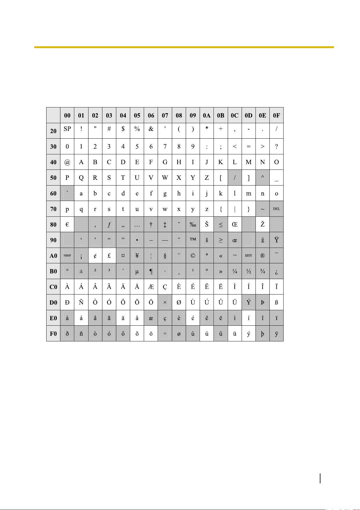
1.1.2 Entering Characters
1.1.2 Entering Characters
The characters
text entry data using a PC. The available characters vary according to the model of PBX.
on a white background below can be used when storing a name, message, password or other
Table 1 (Standard)
PC Programming Manual 13
Page 14
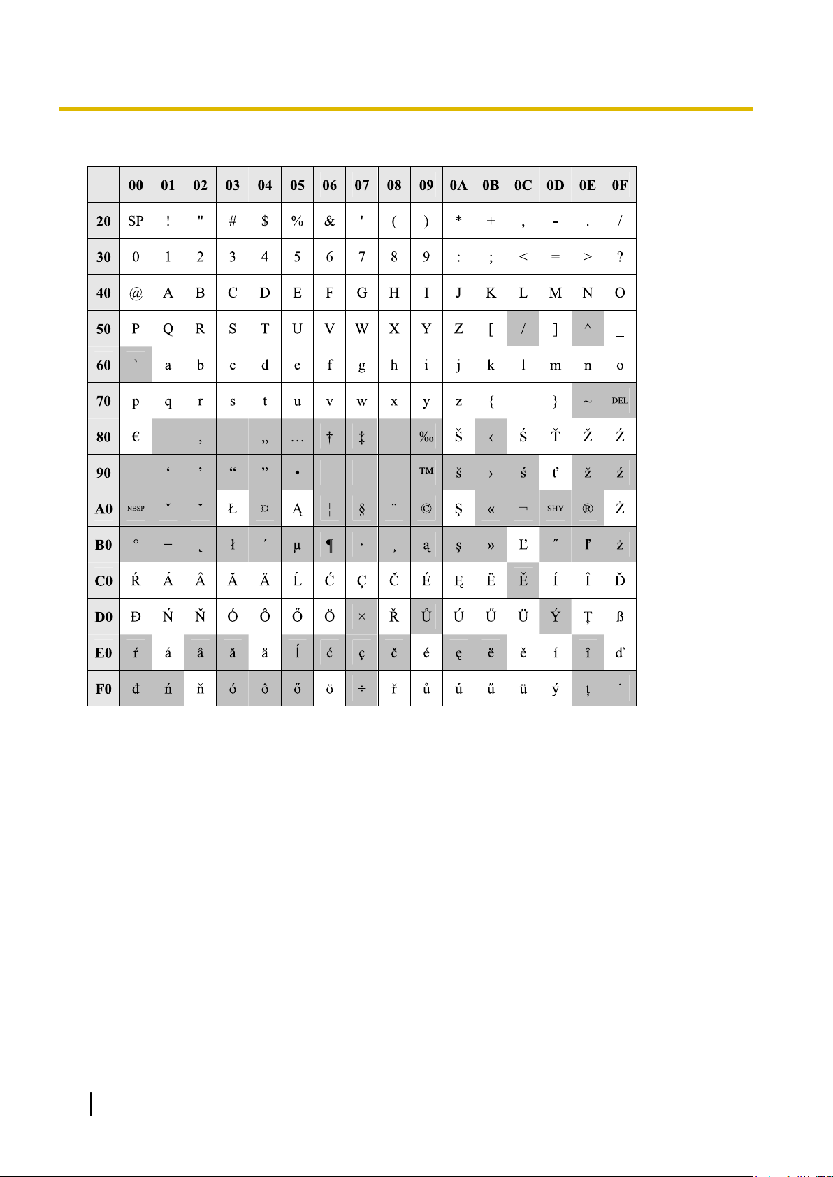
1.1.2 Entering Characters
Table 2 (For CE model)
14 PC Programming Manual
Page 15
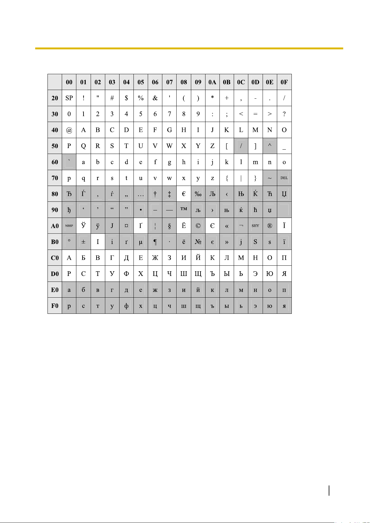
Table 3 (For RU model)
1.1.2 Entering Characters
PC Programming Manual 15
Page 16
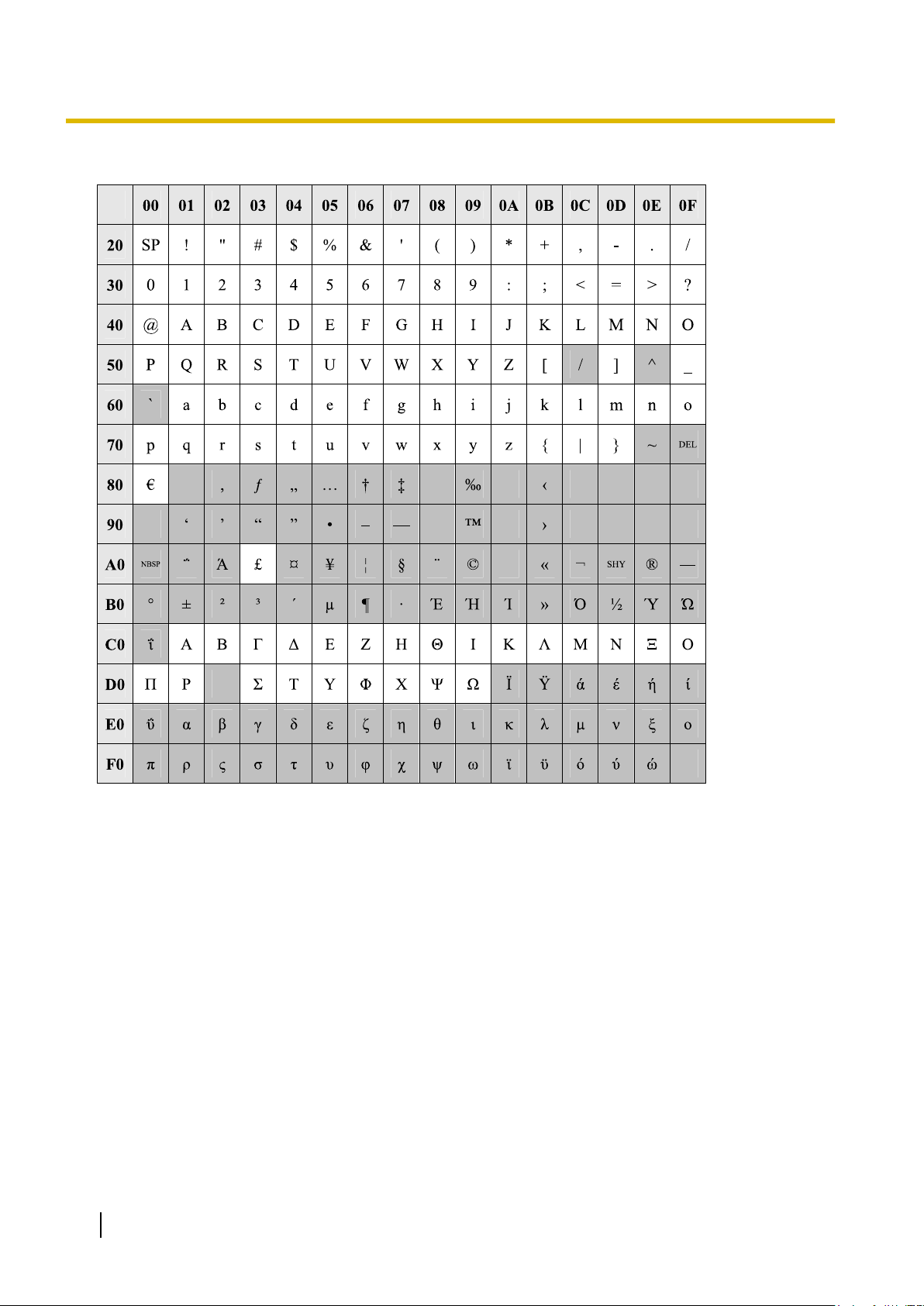
1.1.2 Entering Characters
Table 4 (For GR model)
16 PC Programming Manual
Page 17

1.2.1 Installing and Starting the Maintenance Console
1.2 PC Programming
1.2.1 Installing and Starting the Maintenance Console
System programming, diagnosis and administration can be performed with a PC using the Maintenance
Console.
This section describes how to install and start the Maintenance Console.
System Requirements
Required Operating System
• Microsoft
Minimum Hardware Requirements
®
Windows® XP or Windows Vista® Business operating system
• HDD: 100 MB of available hard disk space
Recommended Display Settings
• Screen resolution: XGA (1024 ´ 768)
• DPI setting: Normal size (96 DPI)
PC Programming Manual 17
Page 18

1.2.1 Installing and Starting the Maintenance Console
Installing the Maintenance Console
Note
• Make sure to install and use the latest version of the Maintenance Console.
• To install or uninstall the software on a PC running Windows XP Professional, you must be logged in
as a user in either the "Administrators" or "Power Users" group.
• To install or uninstall the software on a PC running Windows Vista Business, you must be logged in
as a user in the "Administrators" group.
1. Copy the setup file of the Maintenance Console to your PC.
2. Double-click the setup file to run the installer.
3. Follow the on-screen instructions provided by the installation wizard.
Starting the Maintenance Console and Assigning the Basic Items (Quick
Setup)
When you start the Maintenance Console with the Installer Level Programmer Code and connect to the PBX
the first time after initialisation (with the factory default setting), Quick Setup will launch automatically. During
for
Quick Setup, you will set up the following basic items. For details about the basic items, refer to "2.3.4 Quick
Setup" in the Feature Guide.
1. Connect the PC to the PBX with an Ethernet straight cable or RS-232C cross cable.
2. Start the Maintenance Console from the Start menu.
3. "Information before programming" appears.
a. Carefully read this important additional information, which includes updates to this and other
manuals.
b. Click OK to close this window.
4.
a. Enter the Installer Level Programmer Code (default: INSTALLER).
Note
There are
ADMIN), and User Level (default: USER). (® 1.2.2 Password Security)
2 other Programmer Codes with limited authorisation: Administrator Level (default:
b. Click OK.
5. Click Connect.
6.
a. Select KX-NCP500/1000 from PBX Model.
b. Select the LAN or RS-232C tab, depending on the type of PC connection with the PBX.
c. Specify the settings as required. (See 2.1.1 Starting Maintenance Console and Software
Modes)
Note
When connecting to the PBX for the first time selecting LAN, the IP Address and Port
Number must be set to 192.168.0.101 and 35300 respectively.
d. Enter the system password for installer (default: 1234).
e. Click Connect.
18 PC Programming Manual
Page 19
1.2.1 Installing and Starting the Maintenance Console
7.
When country/area data do not match:
a. Click OK to
replace the country/area data of the PBX. Replacement may take several minutes to
complete.
b. Follow the procedure described in Section 3.13.1 Starting the PBX in the Installation Manual and
restart the PBX.
c. Repeat step 5 to reconnect the Maintenance Console to the PBX.
8. Follow the instructions of the Quick Setup wizard for the basic items in Quick Setup.
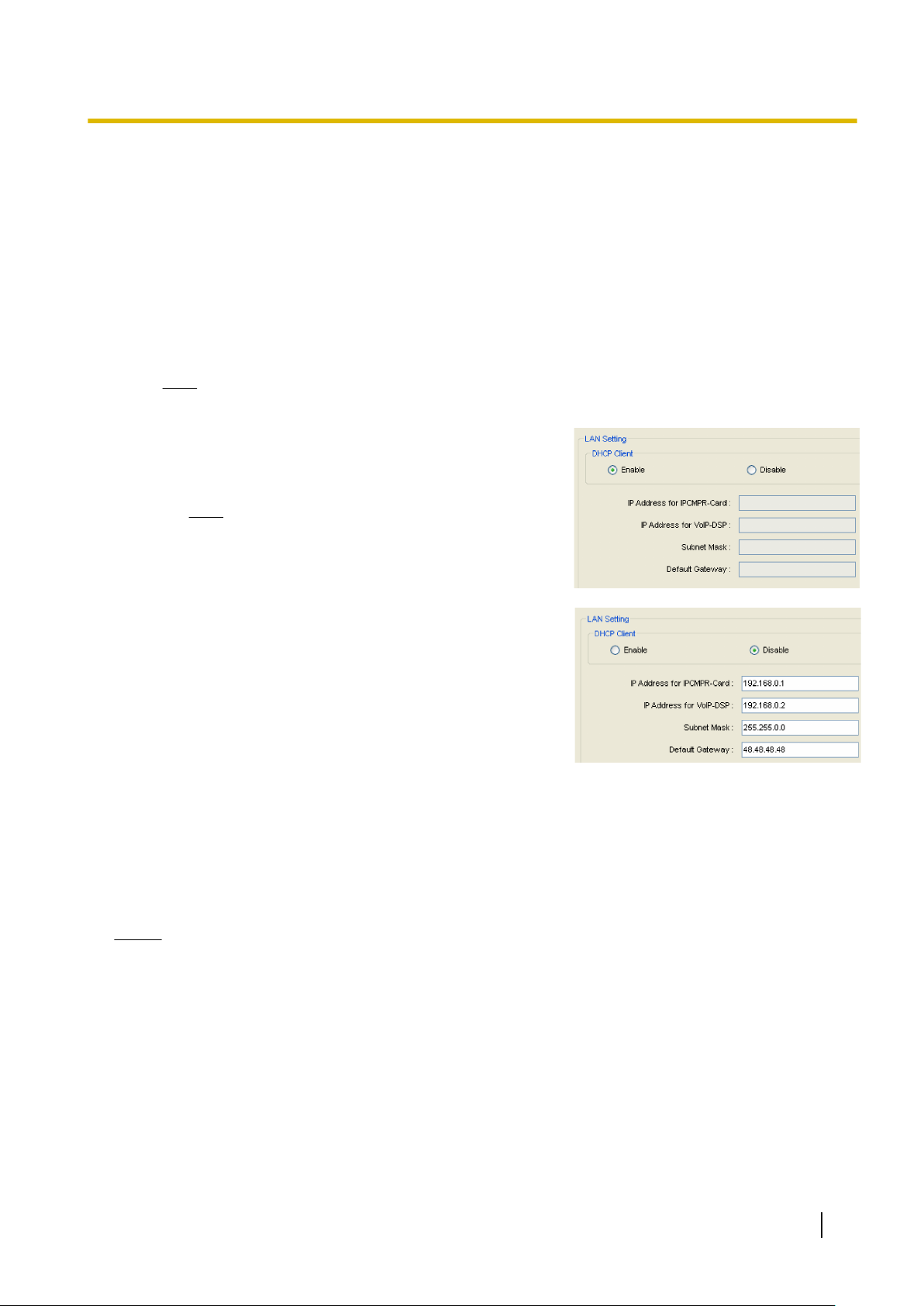
9. On the IP addressing information screen, the information for the IPCMPR card can be assigned
automatically through a DHCP server or entered manually.
Note
If you change any information on this screen and click Apply, the PBX will need to be reset.
When using a DHCP server:
a. Select Enable for the DHCP Client setting.
b. Click Apply.
Note
The boxes
be assigned automatically after the PBX is reset.
will turn grey and the IP addresses will
When not using a DHCP server:
a. Select Disable for the DHCP Client setting.
b. In the IP Address
address of the IPCMPR card.
for IPCMPR Card box, type the IP
*1
c. In the IP Address for VoIP-DSP box, type the IP
address of the DSP card.
*2
d. In the Subnet Mask box, type the subnet mask
address of the network.
*3
e. In the Default Gateway box, type the IP address of
the default gateway.
*4
f. Click Apply.
After Quick Setup is completed, if the IP addressing information was not changed, the IP-PT registration
screen is
displayed. For information on registering IP-PTs to the PBX, see 3.15 [1-1] Slot—Port Property
- Virtual IP Extension.
You may now begin programming the PBX.
Notice
• Do not
change the IP addresses of the IPCMPR and DSP cards once IP telephones are registered to
the PBX using these IP addresses.
The IP telephones will not operate properly if these IP addresses are changed.
• A DHCP server must be able to use a "client identifier" option specified by RFC 2131.
• The PBX will not start properly if the IP addresses cannot be assigned automatically by the DHCP
server when DHCP Client is set to Enable. In this case, you need to consult your network administrator
because the DHCP server on your network may not be running or a network failure may have occurred.
If the DHCP server is not available, change the DHCP Client setting to Disable and set fixed IP
addresses, then restart the PBX.
To change the DHCP Client setting, connect the PC with an RS-232C cross cable or Ethernet straight
cable. When connecting the PC with an Ethernet straight cable, make sure the PBX is disconnected
PC Programming Manual 19
Page 20
PBX Server
Client
Remote PC
IP Network
PBX
Server/Client
1.2.1 Installing and Starting the Maintenance Console
from the LAN and then connect the PC with an Ethernet straight cable using 192.168.0.101 for the IP
address of the IPCMPR card.
*1
Valid IP address range: "1.0.0.0" to "223.255.255.255"
*2
Valid IP address range: "1.0.0.0" to "223.255.255.255
*3
Valid subnet mask address range: "0–255.0–255.0–255.0–255" (except 0.0.0.0 and 255.255.255.255)
*4
Valid IP address range: "0.0.0.0" to "223.255.255.255"
"
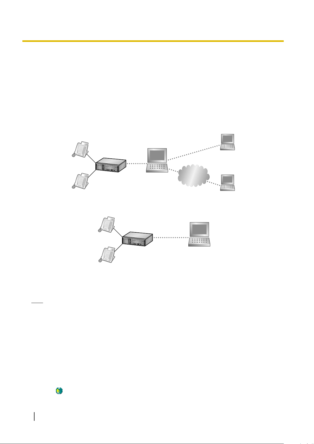
PBX Web Manager
It is possible to use a PC with the Maintenance Console (PBX Unified PC Maintenance Console) installed, as
a web server. This allows users to configure the PBX via a web browser on a local client, or a remote PC
through the Internet.
If Maintenance Console is installed on the client PC, a web server is not necessary.
Accessing PBX Web Manager
Web
PBX
Manager can be enabled during the installation of the Maintenance Console. It can also be enabled
in Options.
Note
• When starting
the Maintenance Console, if there is less than 80 MB of available memory, this feature
is automatically disabled.
• Only one user can access Maintenance Console or PBX Web Manager at any given time.
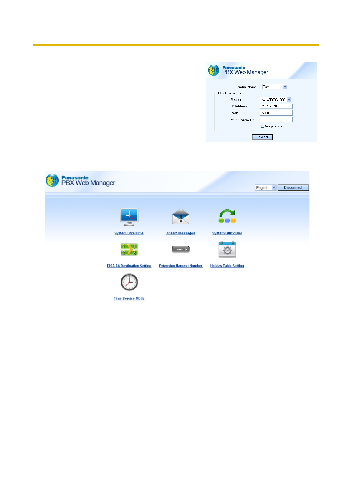
To start PBX Web Manager:
1. If the PC is not the web server:
Launch a web browsing application and enter the
following URL:
"http://xxx:8181/INDEX.ASPX"
’xxx’ should be replaced with the server’s IP address.
If the PC is the web server:
Double-click the PBX Web Manager icon in the system
tray(
20 PC Programming Manual
).
Page 21
1.2.1 Installing and Starting the Maintenance Console
2. At the login screen input the PBX’s IP
address, port, and
password.
Any profiles using LAN connection that have been saved
when accessing the Maintenance Console directly will
be automatically displayed, for easy access to your PBX.
3. Click Connect.
PBX Web Manager Main Menu
After successful login the main menu will appear where settings can be changed.
Note
While logged in, if there is no activity over a 5-minute period, PBX Web Manager will automatically
disconnect.
PC Programming Manual 21
Page 22

1.2.2 Password Security
1.2.2 Password Security
To maintain system security, system passwords are required to access certain programming functions of the
PBX. By giving different users access to different passwords, it is possible to control the amount of
programming that each user is able to perform.
The following types of system passwords are available:
Password Description Format
System Password for User Used with the user-level programmer code to access
user-level PC programming. The installer can specify
which system programming settings are available.
System Password for
Administrator
System Password for
Installer
The three programmer codes used for PC programming can be set through Maintenance Console. For more
information about programmer codes, see 2.1.2 Access Levels.
Used with the administrator-level programmer code to
access administrator-level PC programming. The
installer can
are available.
Used with the installer-level programmer code to access
installer-level
settings are available.
specify which system programming settings
programming. All system programming
PC
4 – 10
characters
CAUTION
To the Administrator or Installer regarding the system password
1. Please provide all system passwords to the customer.
2. To avoid
the customer of the importance of the passwords, and the possible dangers if they become known to
others.
3. The PBX has default passwords preset. For security, change these passwords the first time that you
programme the PBX.
4. Change the passwords periodically.
5. It is strongly recommended that passwords of 10 numbers or characters be used for maximum
protection against unauthorised access. For a list of numbers and characters that can be used in system
passwords, see 1.1.2 Entering Characters.
unauthorised access and possible abuse of the PBX, keep the passwords secret, and inform
22 PC Programming Manual
Page 23

Section 2
Introduction of Maintenance Console
This section serves as reference operating instructions
when using the Maintenance Console software to
programme the PBX.
PC Programming Manual 23
Page 24

2.1.1 Starting Maintenance Console and Software Modes
2.1 Introduction
2.1.1 Starting Maintenance Console and Software Modes
Every time Maintenance Console is started, a dialogue box will appear. From here, you can enter any of the
2 available software modes.
• Batch mode
Batch mode
on your PC, without being connected to the PBX. When you connect to the PBX, the modified data will be
uploaded at one time.
• Interactive mode
Interactive mode allows you to directly modify the system data and settings stored in the PBX’s memory
from a PC that is connected to the PBX. This mode displays the system data that is currently being used
by the PBX, rather than the system data stored on the SD memory card. Data can be modified and results
displayed in real time.
To start Maintenance Console in Batch mode
1. Enter the relevant programmer code.
2. Click OK.
The programme launcher will appear.
3. Select an option.
• Select New to create a new system data file.
• Select Open to open an existing system data file.
allows you to create new system data files, and make modifications to system data files stored
To start Maintenance Console in Interactive mode
1. Enter the relevant programmer code.
2. Click OK.
The programme launcher will appear.
3. Click Connect.
Connection options will be displayed.
• Select a Profile Name if you want to use a pre-saved profile. This option is only available when one
or more profiles have been previously stored.
a. Select the profile to use from the drop-down list.
b. If the system password for the PBX has not been stored with the profile, enter it.
If the system password has been stored with the selected profile, it does not need to be entered.
• To enter the parameters manually, select the PBX Model and select the method of connecting to the
PBX.
a. Specify the settings as required. For more details, see the tables below.
b. Enter the system password for the PBX.
4. Click Connect.
Maintenance Console will start, and automatically connect to the PBX. If this is the first time that
Maintenance Console has connected to the PBX, and the date and time of the PBX have not yet been set,
the Quick Setup wizard will run. For more details, see Starting the Maintenance Console and Assigning
the Basic Items (Quick Setup).
24 PC Programming Manual
Page 25

2.1.1 Starting Maintenance Console and Software Modes
Connection Settings for RS-232C
Setting Values Explanation
Port COMx Specify the number of the COM
port assigned to the PC’s
RS-232C interface. Only
available COM ports are
displayed.
Baud Rate (bps) 2400, 4800, 9600, 19200,
38400, 57600, 115200
Specify the speed of data
transmission.
Connection Settings for Modem
Setting Values Explanation
Dial Number 1-9, 0, *, #, -, "," [comma], T, P,WEnter the telephone number to
be dialled to access the PBX.
T: Converts
Pulse to Tone.
"," [comma], P, W: Inserts a
pause.
Dial Type Auto(Tone), Auto(Pulse),
Manual
Comment Max. 40 characters Enter a comment to identify the
Port COMx Specify the number of the COM
Specify the outgoing dialling
method.
If Manual is chosen, dialling
must
telephone.
set of values.
port assigned to the PC’s
modem interface.
Only available COM ports will
be displayed.
the Dial Type from
done with a connected
be
Baud Rate (bps) 1200, 2400, 4800, 9600,
19200, 38400
Modem Initialise – Enter the modem initialise
Specify the speed of data
transmission.
command, and click Initialise
to send the command to the
modem.
For more details, refer to your
modem’s instruction manual.
Connection Settings for LAN
Setting Values Explanation
IP Address 1.0.0.0–223.255.255.255 Specify the IP address of the
PBX
IP address that was input in IP
Address of 3.4 [1-1] Slot—
Card Property - IPCMPR.
the LAN. Enter the same
on
PC Programming Manual 25
Page 26

2.1.1 Starting Maintenance Console and Software Modes
Setting Values Explanation
Port Number 1–65535 Specify the port number used to
access the PBX via LAN. Enter
the same port number that was
input in Maintenance Port
Number of 3.4 [1-1] Slot—
Card Property - IPCMPR.
Connection Setting for ISDN Remote
Setting Values Explanation
Dial Number 30 digits (consisting of 1-9, 0, *,
#, -, and "," [comma])
Enter the telephone number to
be dialled to access the PBX.
26 PC Programming Manual
Page 27

2.1.2 Access Levels
2.1.2 Access Levels
There are three main levels of access to the Maintenance Console: User, Administrator and Installer. Each
level has its own Programmer Code, which must be entered to run the Maintenance Console. The allowed
format for each programmer code is as follows:
Item Length
User Level Programmer Code 0 – 16 characters
Administrator Level Programmer Code 4 – 16 characters
Installer Level Programmer Code 4 – 16 characters
Access to menu options within the Maintenance Console is restricted depending on the Programmer Code,
and the current software mode (see 2.1.1 Starting Maintenance Console and Software Modes). When a
menu option is limited to certain access levels, this is noted in this manual in the initial description of that menu
option, for example:
"This option is only available at Installer level."
If a sentence like this does not appear under the heading, the menu option is available at all levels.
The target users for each access level are as follows:
Access Level User
User For end users
Administrator For system administrators
Installer For dealers and system installers
The options available in each mode and access level are shown below.
The access levels are abbreviated as follows:
U: User; A: Administrator; I: Installer
A check mark indicates that the menu option is available for that access level.
Programme launcher
Menu Option
New
Open
Connect—RS-232C
Connect—USB
Batch Interactive
U A I U A I
ü ü
ü ü ü ü ü ü
ü ü ü ü ü ü
ü ü ü ü ü ü
Connect—LAN
Connect—Modem
Connect—ISDN Remote
Connect—Profile Setup
ü ü ü ü ü ü
ü ü ü ü ü ü
ü ü ü ü ü ü
ü ü ü ü ü ü
PC Programming Manual 27
Page 28
2.1.2 Access Levels
File
Close
Save
Save As
Exit
Disconnect
Disconnect
Tool
SD memory backup
Menu Option
Menu Option
Menu Option
Batch Interactive
U A I U A I
ü ü ü
ü ü ü
ü ü ü
ü ü ü ü ü ü
Batch Interactive
U A I U A I
ü ü ü
Batch Interactive
U A I U A I
ü ü ü
BRI Automatic Configuration
NDSS Link Data Clear
DXDP All OUS
Simplified Voice Message®Delete All Recording
Simplified Voice Message®Check Current Usage
Call Pickup for My Group
Extension List View
Import®Feature - Speed Dial and Caller ID
Import®Incoming Call - DDI/DID Table
Import®ARS - Leading Digit
Import®ARS - Except Code
Import®ARS - Routing Plan
Import®Wired Extension
Import®PS Extension
Import®Quick Dial (Basic)
Import®Quick Dial (Expansion)
ü
ü
ü
ü
ü
ü ü
ü ü ü ü ü ü
ü ü ü ü ü ü
ü ü
ü ü
ü ü
ü ü
ü ü
ü ü
ü ü
ü ü
Import®SIP Extension
28 PC Programming Manual
ü ü
Page 29
2.1.2 Access Levels
Menu Option
Import®V-IPGW16 GW Settings
Import®V-IPGW16 DN2IP
Export®Feature - Speed Dial and Caller ID
Export®Incoming Call - DDI/DID Table
Export®ARS - Leading Digit
Export®ARS - Except Code
Export®ARS - Routing Plan
Export®Wired Extension
Export®PS Extension
Export®Quick Dial (Basic)
Export®Quick Dial (Expansion)
Export®SIP Extension
Export®V-IPGW16 GW Settings
Batch Interactive
U A I U A I
ü ü
ü ü
ü ü ü ü ü ü
ü ü
ü ü
ü ü
ü ü
ü ü
ü ü
ü ü
ü ü
ü ü
ü ü
Export®V-IPGW16 DN2IP
Screen Customize®User Level
Screen Customize®Administrator Level
Utility
Menu Option
Diagnosis
File Transfer PC to PBX (SD Card)
File Transfer PBX (SD Card) to PC
SD Card File View and Load
SD Card File Delete
Message File Transfer PC to PBX
Message File Transfer PBX to PC
Error Log
T1/E1 Signalling Bit Monitor
ü ü
ü ü
ü ü
Batch Interactive
U A I U A I
ü ü ü
ü
ü
ü
ü
ü
ü
ü ü ü
ü
T1/E1 Line Trace
ISDN/QSIG Protocol Trace
V-IPGW16 Protocol Trace
ü
ü
ü
PC Programming Manual 29
Page 30
2.1.2 Access Levels
Menu Option
Digital Trunk Error Report
IP Extension Statistical Information
CS Information
PS Information
CS Status Monitor
Ping
File Transfer FTP to IP Equipment®IP-CS
File Transfer FTP to IP Equipment®NT400
Card Software Timed Update
System Reset®Reset by the Command
View
Menu Option
Batch Interactive
U A I U A I
ü
ü
ü
ü
ü
ü
ü
ü
ü
ü
Batch Interactive
Toolbar
Statusbar
System Menu
Window
Cascade
Tile(Horz)
Tile(Vert)
Help
Help
Menu Option
Menu Option
U A I U A I
ü ü ü ü ü ü
ü ü ü ü ü ü
ü ü ü ü ü ü
Batch Interactive
U A I U A I
ü ü ü ü ü ü
ü ü ü ü ü ü
ü ü ü ü ü ü
Batch Interactive
U A I U A I
ü ü ü ü ü ü
Additional Information
About
30 PC Programming Manual
ü ü ü ü ü ü
ü ü ü ü ü ü
Page 31

1 23
45 6
2.1.3 Software Interface
2.1.3 Software Interface
This section explains the functions of the various elements of the software interface.
Main Window
The window of the Maintenance Console software is divided into several areas, as shown below:
1. Menu Bar
Provides access to file management and connection options, as well as tools and utilities used in
programming the PBX.
For details, see Sections 2.3 File to 2.7 Help.
2. Tool Bar
Provides easy access to commonly used software functions.
Two tool bars are provided, as follows:
PC Programming Manual 31
Page 32

2.1.3 Software Interface
• File
Contains the icon for saving files. For details, see Section 2.3.2 File—Save.
• Tools
Contains icons for backing up PBX data to the SD Memory Card, viewing extension information, and
accessing Online Help. For details, see Sections 2.5.1 Tool—SD memory backup and 2.5.8 Tool
—Extension List View.
These menus
It will automatically snap in to position above, below, to the left, or to the right of the main window if released
there. Otherwise, it will float separately from the main window.
Whether the tool bar is displayed or not can be chosen by selecting Toolbar from the View menu.
3. Tab Bar
The name of each screen currently open is displayed in a tab in this tab bar. When multiple screens are
open at the same time, click on the tab of a screen to display the options associated with that screen.
4. System Menu
Provides access to the settings used for programming the PBX, grouped into 11 topics.
For details, see Sections Section 3 [1] Configuration to Section 13 [11] Maintenance.
To display the individual screens within a topic, click the topic heading. It will expand to show the sub-topics.
• If a sub-topic contains more than one screen, clicking the name of the sub-topic will display the names
of individual screens. Clicking an expanded sub-topic will hide the names of individual screens.
Double-click on a screen name to open that screen in 6. Main Screen below.
This menu can be positioned freely. Click and drag the title bar of the menu to move it to another position.
It will automatically snap in to either the left side or right side of the main window if released there.
Otherwise, it will float separately from the main window.
Whether the system menu is displayed or not can be chosen by selecting System Menu from the View
menu.
5. Status Bar
The status bar displays information on the current state of the Maintenance Console.
Whether the status bar is displayed or not can be chosen by selecting Statusbar from the View menu.
can be positioned freely. Click and drag the title bar of a menu to move it to another position.
The information displayed is as follows, in order from left to right:
Area Values Description
Programme Mode
and Connection
Type
PBX Type Type: NCP500/
Access Level Level :
Programme Mode:
Batch Mode xxx
Interactive Mode yyy
Connection Type:
RS-232C
USB
LAN
Modem
ISDN Remote
NCP1000
User
Administrator
Installer
Displays the current programme mode and
connection type. See 2.1.1 Starting
Maintenance Console and Software Modes
above.
"xxx" is replaced by the name of the current
system data file.
is
"yyy"
Displays the type of PBX being programmed.
Displays the current access level, determined by
the Programmer Code entered when starting
Maintenance Console. See 2.1.2 Access
Levels for more information.
replaced by the name of the profile if used.
32 PC Programming Manual
Page 33

Area Values Description
2.1.3 Software Interface
PBX System Data
Version
PBX Region Code Regionxxx-xxx Displays the region code assigned to the PBX and
Versionxxx-xxx Displays the version number of the system
software installed to the PBX.
The first 3 digits are the version number, and the
last 3 digits are the revision number.
Maintenance Console.
The first 3 digits represent the region code
assigned to the PBX, and the last 3 digits
represent the region code assigned to the
Maintenance Console.
6. Main Screen
Displays the screens selected from 4. System Menu above.
For details, see Sections Section 3 [1] Configuration to Section 13 [11] Maintenance.
Standard Buttons and Elements
There are several standard buttons that are displayed on many screens within the Maintenance Console.
The standard buttons are as follows:
Button Function
OK Implements changes and closes the current screen.
Cancel Abandons changes and returns to the previous screen.
Close Keeps any changes implemented, and closes the current screen.
Apply Implements changes and remains on the same screen.
Refresh Implements changes, updates displayed data, and remains on the
current screen.
Help Displays the relevant help topic for the current screen.
In addition, many screens within the software display a small open folder icon ( ) beside lists of setting items.
Clicking this icon will collapse part of the list, allowing other items to be displayed. The icon will change to a
closed folder ( ).
Clicking the closed folder icon will expand the list again.
PC Programming Manual 33
Page 34

2.1.4 Card Status
2.1.4 Card Status
Certain tools,
status before the operation is carried out. Where required, this is noted in the description of each item. Card
status changes can only be performed when the software is in Interactive mode (see 2.1.1 Starting
Maintenance Console and Software Modes).
utilities and settings require that the target card be set to out-of-service (OUS) or in-service (INS)
• "In service" means that the card is installed correctly in the PBX, and is capable of being used normally.
• "Out of service" means that the card is installed correctly in the PBX, but has been temporarily removed
from use. This allows settings to be modified or software to be upgraded.
• "Fault" means that the card is not installed in the PBX correctly, or is not functioning correctly. For more
information, see the Installation Manual.
For details about how to change the status of a card, see To change the status (INS/OUS) of a card
(Interactive mode only) on screen 3.1 [1-1] Slot.
34 PC Programming Manual
Page 35

2.1.5 Display Options
2.1.5 Display Options
The View
and Window menus provide options to control the display of items within the Maintenance Console.
• View
– Toolbar: Displays or hides the tool bar of commonly used buttons.
– Statusbar: Displays or hides the bar at the bottom of the Maintenance Console window.
– System Menu: Displays or hides the menu of PBX setting screens.
• Window
– Cascade: When multiple data screens are open, displays all open screens overlapped, with the title
bars visible.
– Tile(Horz): When multiple data screens are open, displays all open screens side by side.
– Tile(Vert): When multiple data screens are open, displays all open screens vertically.
PC Programming Manual 35
Page 36

2.1.6 Extension Number Setting
2.1.6 Extension Number Setting
Many screens
various features (for example, as members of a group). These screens use a standard window to make
selecting multiple extensions easy, accessed by clicking a button. This section explains how to use this
Extension Number Setting window.
To select multiple extension numbers, select the type of extension to display, highlight the extensions you wish
to add, then click the Add button. When finished, click OK. Data for the selected extensions will be added to
the first free spaces on the original screen.
within the Maintenance Console software allow you to select extensions as part of programming
Extension Type
Selects the types of extension numbers to display in
can be selected. Items that are not available are shown with a grey checkbox.
Value Range
Wired Extension, Portable Station, VM Group(DPT), VM Group(DTMF), ICD Group, PS Ring Group,
OGM(DISA), External Pager, Analogue MODEM, ISDN Remote
Extension Numbers & Names List. Multiple items
Extension Numbers & Names List
Displays all
them, and click the Add button when finished, to add the selected extensions. To deselect an entry, click it
again.
available extensions of the types selected in
Extension Type, and
names. Click entries to select
Value Range
Matching extensions
Available Column
Specifies which fields in the original form to add extension data to. For example, if both extension numbers
and names can be entered in the original form, it is possible to specify that extension name data not be
transferred, by deselecting that field here.
To select or deselect a field, click its name.
Value Range
Available fields
Selected Extension List
Displays the extensions that have been selected to be added to member data. To remove an extension from
this list, click it to select it and click Delete.
Value Range
Selected extensions
36 PC Programming Manual
Page 37

2.2.1 Programme launcher—New
2.2 Programme launcher
2.2.1 Programme launcher—New
Creates a new system data file, used to programme the PBX in Batch mode. All settings are in their initial or
default state.
This option is only available at Installer level.
To upload
PC to PBX (SD Card).
Note
To create a new system data file
1. From the programme launcher, select New.
2. Click the appropriate model number.
3. Click OK.
the file created here to the SD memory card installed in the PBX, see 2.6.2 Utility—File Transfer
Since selecting
previous settings. Use only when necessary.
this option creates a blank system data file, uploading this file to the PBX will overwrite all
PC Programming Manual 37
Page 38

2.2.2 Programme launcher—Open
2.2.2 Programme launcher—Open
Opens a system data file previously saved on the PC, and enters Batch mode.
When opening
want to convert the data for use with the current version or not. Using the data without converting may result
in some data being loaded to an incorrect destination, and is not recommended.
If the file is not supported by the PBX (e.g. a system data file from an incompatible PBX), it will not be opened.
The only files that can be opened are files that were created by the Maintenance Console for a supported PBX.
To upload a file opened here to the SD memory card installed in the PBX, see 2.6.2 Utility—File Transfer
PC to PBX (SD Card).
a file created with an older version of the Maintenance Console, you will be asked whether you
To open a system data file
1. From the programme launcher, select Open.
The Open dialogue box will be displayed.
2. Navigate to the folder containing the system data file you want to open.
3. Select the file.
4. Click Open.
If the file was created with an older version of the Maintenance Console, you will be asked if you want to
convert the data.
• Click Yes to convert the data for use with the current version of the Maintenance Console. Enter a
name for the new converted system file.
• Click No to open the file as it is.
38 PC Programming Manual
Page 39

2.2.3 Programme launcher—Connect—RS-232C
2.2.3 Programme launcher—Connect—RS-232C
Connects to the PBX in Interactive mode through the serial RS-232C interface of the PBX.
This option
just a few PBXs, and an individual profile for each PBX is not necessary. If you connect to multiple PBXs and
would prefer to choose from among pre-saved profiles instead, see 2.2.8 Programme launcher—Connect
—Profile Setup for more details about creating profiles.
To connect to the PBX by RS-232C
1. From the programme launcher, select Connect.
The Login window will be displayed.
2. Select a connection option.
• Select a Profile Name if you want to use a pre-saved profile. This option is only available when one
• To enter the parameters manually, select the PBX Model and confirm that the RS-232C radio button
3. Click Connect.
allows direct entry of connection parameters, for cases where the PC is used to connect to one or
or more profiles have been previously stored.
a. Select the profile to use from the drop-down list.
b. If the system password for the PBX has not been stored with the profile, enter it.
If the system password has been stored with the selected profile, it does not need to be entered.
is selected.
a. Specify the settings as required. For more details, see the table below.
b. Enter the system password for the PBX.
Connection Settings for RS-232C
Setting Values Explanation
Port COMx Specify the number of the COM port
assigned to the PC’s RS-232C interface.
Only available COM ports are displayed.
Baud Rate (bps) 2400, 4800, 9600, 19200,
38400, 57600, 115200
Specify the speed of data transmission.
PC Programming Manual 39
Page 40

2.2.4 Programme launcher—Connect—USB
2.2.4 Programme launcher—Connect—USB
Connects to
or KX-T7600 series DPT.
the PBX in Interactive mode through a USB port (USB Module) attached to the KX-DT300 series
To connect to the PBX by USB
1. From the programme launcher, select Connect.
The Login window will be displayed.
2. Select a connection option.
• Select a Profile Name if you want to use a pre-saved profile.
a. Select the profile to use from the drop-down list.
b. If the system password for the PBX has not been stored with the profile, enter it.
If the system password has been stored with the selected profile, it does not need to be entered.
• To enter the parameters manually, select the PBX Model and confirm that the USB radio button is
selected.
a. Enter the system password for the PBX.
3. Click Connect.
40 PC Programming Manual
Page 41

2.2.5 Programme launcher—Connect—LAN
2.2.5 Programme launcher—Connect—LAN
Connects to the PBX in Interactive mode through the Local Area Network interface of the PBX.
This option
just a few PBXs, and an individual profile for each PBX is not necessary. If you connect to multiple PBXs and
would prefer to choose from among pre-saved profiles instead, see 2.2.8 Programme launcher—Connect
—Profile Setup for more details about creating profiles.
To connect to the PBX by LAN
1. From the programme launcher, select Connect.
The Login window will be displayed.
2. Select a connection option.
• Select a Profile Name if you want to use a pre-saved profile.
• To enter the parameters manually, select the PBX Model and confirm that the LAN radio button is
3. Click Connect.
allows direct entry of connection parameters, for cases where the PC is used to connect to one or
a. Select the profile to use from the drop-down list.
b. If the system password for the PBX has not been stored with the profile, enter it.
If the system password has been stored with the selected profile, it does not need to be entered.
selected.
a. Specify the settings as required. For more details, see the table below.
b. Enter the system password for the PBX.
Connection Settings for LAN
Setting Values Explanation
IP Address 1.0.0.0–
223.255.255.255
Port Number 1–65535 Specify the port number used to access the
Specify the IP address of the PBX on the
LAN. Enter the same IP address that was
input in IP Address for IPCMPR Card of
[1-1] Slot—Card Property - IPCMPR.
3.4
PBX via LAN. Enter the same port number
that was input in Maintenance Port
Number
- IPCMPR.
[1-1] Slot—Card Property
of 3.4
PC Programming Manual 41
Page 42

2.2.6 Programme launcher—Connect—Modem
2.2.6 Programme launcher—Connect—Modem
Connects to the PBX in Interactive mode through the modem.
To access
Remote (Modem) Floating Extension Number assigned in 13.1 [11-1] Main.
This option
just a few PBXs, and an individual profile for each PBX is not necessary. If you connect to multiple PBXs and
would prefer to choose from among pre-saved profiles instead, see 2.2.8 Programme launcher—Connect
—Profile Setup for more details about creating profiles.
To connect to the PBX by Modem
1. From the programme launcher, select Connect.
The Login window will be displayed.
2. Select a connection option.
• Select a Profile Name if you want to use a pre-saved profile.
• To enter the parameters manually, select the PBX Model and confirm that the Modem radio button is
3. Click Connect.
the PBX remotely using this feature, an RMT card must be installed and the
allows direct entry of connection parameters, for cases where the PC is used to connect to one or
Remote—Analogue
a. Select the profile to use from the drop-down list.
b. If the system password for the PBX has not been stored with the profile, enter it.
If the system password has been stored with the selected profile, it does not need to be entered.
selected.
a. Specify the settings as required. For more details, see the table below.
b. Enter the system password for the PBX.
Connection Settings for Modem
Setting Values Description
Dial Number 1-9, 0, *, #, -,
"," [comma], T, P, W
Dial Type Auto(Tone),
Auto(Pulse), Manual
Comment Max. 40 characters Enter a comment to identify the set of values.
Port COMx Specify the number of the COM port
Baud Rate (bps) 1200, 2400, 4800, 9600,
19200, 38400
Modem Initialise – Enter the modem initialise command, and
Enter the telephone number to be dialled to
access the PBX.
T: Converts the Dial Type from Pulse to
Tone.
"," [comma], P, W: Inserts a pause.
Specify the outgoing dialling method.
If Manual is chosen, dialling must be done
with a connected telephone.
assigned to the PC’s modem interface.
Only available COM ports will be displayed.
Specify the speed of data transmission.
click Initialise to send the command to the
modem.
For more details, refer to your modem’s
instruction manual.
42 PC Programming Manual
Page 43

2.2.7 Programme launcher—Connect—ISDN Remote
2.2.7 Programme launcher—Connect—ISDN Remote
Connects to the PBX in Interactive mode using the ISDN TA interface of the PBX.
This method
—ISDN Remote Floating Extension Number of the 13.1 [11-1] Main screen is set.
This option
just a few PBXs, and an individual profile for each PBX is not necessary. If you connect to multiple PBXs and
would prefer to choose from among pre-saved profiles instead, see 2.2.8 Programme launcher—Connect
—Profile Setup for more details about creating profiles.
To connect to the PBX by ISDN Remote
1. From the programme launcher, select Connect.
The Login window will be displayed.
2. Select a connection option.
• Select a Profile Name if you want to use a pre-saved profile.
• To enter the parameters manually, select the PBX Model and confirm that the ISDN Remote radio
3. Click Connect.
is only available when a user-supplied ISDN TA that supports CAPI 2.0 is used, and
allows direct entry of connection parameters, for cases where the PC is used to connect to one or
a. Select the profile to use from the drop-down list.
b. If the system password for the PBX has not been stored with the profile, enter it.
If the system password has been stored with the selected profile, it does not need to be entered.
button is selected.
a. Specify the settings as required. For more details, see the table below.
b. Enter the system password for the PBX.
Remote
Connection Setting for ISDN Remote
Setting Values Explanation
Dial Number 30 digits (consisting of
1-9, 0, *, #, -, and
"," [comma])
Enter the telephone number to be dialled to
access the PBX.
PC Programming Manual 43
Page 44

2.2.8 Programme launcher—Connect—Profile Setup
2.2.8 Programme launcher—Connect—Profile Setup
Profiles are useful when one PC is used to connect to multiple PBXs. Rather than manually adjusting the
connection settings each time a different PBX is accessed, it is possible to store the connection settings for
several PBXs. Then, when you wish to connect to a specific PBX, you can simply choose that PBX’s profile
from the list.
Note
When reinstalling or upgrading the Maintenance Console, it is possible to create a backup of all profiles.
This allows you to use the original connection settings with the new Maintenance Console.
The functions of the buttons on this screen are as follows:
Button Function
Profile File Opens or saves profiles as separate files.
Save current
profile
Save as new
profile
Delete profile When an existing profile is selected, deletes that profile. A confirmation message will
Overwrites the previous settings with the current settings when a profile already exists.
A confirmation message will be displayed.
Saves the current settings as a new profile. A Profile Name is required.
be displayed.
44 PC Programming Manual
Page 45

2.3 File
2.3.1 File—Close
Closes the system data file that is currently being modified, and returns to the programme launcher.
To close a system data file
• From the File menu, select Close.
If the system data file has not been saved, a warning message will be displayed, giving you the option to
save the file.
• Click Yes to save the file.
• Click No to abandon the changes.
2.3.1 File—Close
PC Programming Manual 45
Page 46

2.3.2 File—Save
2.3.2 File—Save
Overwrites the
To upload a file saved here to the SD memory card installed in the PBX, see 2.6.2 Utility—File Transfer PC
to PBX (SD Card).
previously saved system data file with the system data currently being modified in Batch mode.
To save a system data file
• From the File menu, select Save.
If the data has never been saved, the Save dialogue box will be displayed. For more details, see 2.3.3 File
—Save As.
46 PC Programming Manual
Page 47

2.3.3 File—Save As
Saves the system data file being modified in Batch mode with the name chosen by the user.
To upload
to PBX (SD Card).
To save a system data file with a new name
1. From the File menu, select Save As.
2. Navigate to the folder in which you want to save the file.
3. Enter a file name, or select a file to overwrite.
4. Click Save.
a file saved here to the SD memory card installed in the PBX, see 2.6.2 Utility—File Transfer PC
If choosing to overwrite another file, a warning message will be displayed.
• Click Yes to overwrite.
• Click No to return to the previous screen.
2.3.3 File—Save As
PC Programming Manual 47
Page 48

2.3.4 File—Exit
2.3.4 File—Exit
Closes the Maintenance Console.
To exit the Maintenance Console
• From the File menu, select Exit
system data file being modified has not been saved, a warning message will be displayed, giving you
the
If
the option to save the file.
• Click Yes to save the file.
• Click No to abandon the changes.
48 PC Programming Manual
Page 49

2.4.1 Disconnect—Disconnect
2.4 Disconnect
2.4.1 Disconnect—Disconnect
Closes the connection between the Maintenance Console and the PBX. When this option is chosen, system
data is automatically backed up from the PBX to the SD memory card (see 2.5.1 Tool—SD memory
backup).
To disconnect
1. From the Disconnect menu, select Disconnect.
A confirmation message will be displayed.
2. Click Yes.
PC Programming Manual 49
Page 50

2.5.1 Tool—SD memory backup
2.5 Tool
2.5.1 Tool—SD memory backup
Saves system data from the PBX to the SD memory card. Backup begins as soon as this option is chosen.
To back up system data
• From the Tool menu, select SD memory backup.
50 PC Programming Manual
Page 51

2.5.2 Tool—BRI Automatic Configuration
2.5.2 Tool—BRI Automatic Configuration
Automatically configures the network settings of the BRI card.
This option is only available at Installer level.
This tool automatically inputs values into the fields L1 Mode, L2 Mode, Access Mode, and TEI
Mode, on the Network tab of the 3.31 [1-1] Slot—Port Property - BRI Port screen.
Note
• Only one card can be configured at a time.
• To use this tool, the card to be configured must be pre-set to OUS status. For more details, see
2.1.4 Card Status.
When configuration is complete, the card is automatically returned to INS status.
• At any time on this screen, you can click
To configure the BRI card
1. From the Tool menu, select BRI Automatic Configuration.
2. Select the BRI card to configure by clicking the Check cell and setting it to ON.
3. Click OK.
The ports associated with the selected BRI card will be displayed on a new screen.
4. Enter suitable Subscriber Numbers for the ports you want to configure.
Only ports whose Subscriber Numbers have been entered will be configured.
5. Click Execute.
The results of configuration will be displayed.
6. Click the Check Box cell for the ports that have been configured.
7. Click Data Apply to save these results to the BRI card.
Close to return to the previous screen without saving.
PC Programming Manual 51
Page 52

2.5.3 Tool—NDSS Link Data Clear
2.5.3 Tool—NDSS Link Data Clear
Clears NDSS Link Data stored in the connected PBX. While this tool clears both monitor extension and
monitored extension
it is necessary to run this tool at those PBXs.
To clear the NDSS Link Data
• From the Tool menu, select NDSS Link Data Clear.
A confirmation screen will be displayed.
• Click OK to clear the data.
• Click Cancel to keep the data, and close the screen.
data, it only clears it at the connected PBX. To clear this data at other PBXs in the network,
52 PC Programming Manual
Page 53

2.5.4 Tool—DXDP All OUS
Sets the status of all DXDP/XDP extension ports to "OUS" simultaneously.
To set all DXDP/XDP ports to OUS.
1. From the Tool menu, select DXDP All OUS.
2. Click OK.
2.5.4 Tool—DXDP All OUS
PC Programming Manual 53
Page 54

2.5.5 Tool—Simplified Voice Message—Delete All Recording
2.5.5 Tool—Simplified Voice Message—Delete All Recording
Deletes all voice messages recorded by the SVM feature.
To delete voice messages
1. From the Tool menu, point to Simplified Voice Message and select Delete All Recording.
2. Select the card from which to delete messages.
3. Click OK.
54 PC Programming Manual
Page 55

2.5.6 Tool—Simplified Voice Message—Check Current Usage
2.5.6 Tool—Simplified Voice Message—Check Current Usage
Displays information on the voice messages stored by the SVM feature. For each message, the type of
message and the associated extension are displayed.
To view SVM message status
• From the Tool menu, point to Simplified Voice Message and select Check Current Usage.
PC Programming Manual 55
Page 56

2.5.7 Tool—Call Pickup for My Group
2.5.7 Tool—Call Pickup for My Group
Allows you to automatically configure settings in 4.10 [2-6-2] Numbering Plan—Quick Dial and 6.4 [4-1-3]
Wired Extension—Speed Dial so that users can answer calls to their Call Pickup Group by pressing " 0".
To activate this tool
• From the Tool menu, select Call Pickup for My Group.
Call Pickup feature number (default:
Group
The
is assigned to first personal speed dial.
Note
This tool can only be activated if all of the following conditions are met:
– The first Quick Dial setting is empty or is already set to "
– " 0" is not used for another feature number.
– The Group Call Pickup feature number has been assigned.
– The Personal Speed Dialling feature number has been assigned.
40) + the extension user group number of the extension
0".
56 PC Programming Manual
Page 57

2.5.8 Tool—Extension List View
2.5.8 Tool—Extension List View
Displays a
to Extension Number, Type, Extension Name, Shelf, Slot, or Port. There is also a key-word searching feature.
The types that can be displayed are as follows:
Type Detail
Intercom Wired Extension
VM Voice Mail
Portable Station Wireless Extension (Portable Station)
ICDG Incoming Call Distribution Group
WG PS Ring Group
VM (DPT) VM (DPT) Group
VM (DTMF) VM (DTMF) Group
Pager External Pager
MODEM Analogue Modem
ISDN Remote ISDN Modem
OGM (DISA) DISA
list of all programmed extension numbers and types. It is possible to sort the information according
DSS DSS Console
DPT-I/F CS PT-interface CS
SVM SVM Feature
SIP/IP-PT IP Telephone
To view extension information
• From the Tool menu, select Extension List View.
PC Programming Manual 57
Page 58

2.5.9 Tool—Import
2.5.9 Tool—Import
Allows several types of system data files or tables to be imported.
Except for Speed Dial and Caller ID, this option is only available at Installer level.
The files from which data can be imported are files that were previously saved at this or another PBX using
the Export tool (see 2.5.10 Tool—Export), or comma-separated value (CSV) files. Unsupported file types
cannot be opened.
tables except ARS - Routing Plan, it is possible to edit the CSV file directly using an appropriate editor,
For all
before importing.
The types of data that can be imported using this tool, and the matching destination fields, are as follows:
Feature - Speed Dial and Caller ID
Data Type Import Destination
System Speed Dialling
Number
Name Name
CO Line Access Number +
Telephone Number
CLI Destination CLI Destination
Related programming: 8.1 [6-1] System Speed Dial
Location
Dial
Incoming Call - DDI/DID Table
Data Type Import Destination
Location Location
DDI/DID Number Dial In Number
DDI/DID Name Dial In Name
DDI/DID Destination-Day Destination-Day
DDI/DID Destination-Lunch Destination-Lunch
DDI/DID Destination-Break Destination-Break
DDI/DID Destination-Night Destination-Night
Tenant Number Tenant Number
VM Trunk Group No. Group Number for VPS
answer
CLI Ring for DDI/DID-Day CLI Ring - Day
CLI Ring for DDI/DID-Lunch CLI Ring - Lunch
CLI Ring for DDI/DID-Break CLI Ring - Break
CLI Ring for DDI/DID-Night CLI Ring - Night
Related programming: 12.3 [10-3] DDI / DID Table
58 PC Programming Manual
Page 59

ARS - Leading Digit
Data Type Import Destination
No. Location
Leading Number Leading Digit
Additional Number of Digits Additional Dial Digits
Routing Plan Number Route Plan Number
Related programming: 10.2 [8-2] Leading Number
ARS - Except Code
Data Type Import Destination
No. Location
Leading Number Exception Exception Code
Related programming: 10.7 [8-6] Leading Number Exception
2.5.9 Tool—Import
ARS - Routing Plan
Data Type Import Destination
(no fields to select) (no fields to select)
Related programming: 10.3 [8-3] Routing Plan Time
Wired Extension
Data Type Import Destination
No. Location (selected
automatically)
Extension Number Extension Number (selected
automatically)
Extension Name Extension Name (selected
automatically)
Related programming: 6.1 [4-1-1] Wired Extension—Extension Settings
PS Extension
Data Type Import Destination
No. Location (selected
automatically)
Extension Number
*1
Extension Number (selected
automatically)
Extension Name Extension Name (selected
automatically)
*1
This data can only be exported, and cannot be imported.
PC Programming Manual 59
Page 60

2.5.9 Tool—Import
Related programming: 6.10 [4-2-1] Portable Station—Extension Settings
Quick Dial (Basic)
Data Type Import Destination
No. Location
Dial Dial
Phone Number Phone Number
Related programming: 4.10 [2-6-2] Numbering Plan—Quick Dial
Quick Dial (Expansion)
Data Type Import Destination
No. Location
Dial Dial
Phone Number Phone Number
Related programming: 4.10 [2-6-2] Numbering Plan—Quick Dial
SIP Extension
Data Type Import Destination
No. Location
Extension Number Extension Number
Password Password
Related programming: 3.18 [1-1] Slot—Port Property - Virtual SIP Extension Port
V-IPGW16 GW Settings
Data Type Import Destination
No. Location
GW Name GW Name
GW IP Address GW IP Address
GW Group GW Group No.
Connection for IP-GW16 Connection for IP-GW16
Protocol Protocol
Progress Tone Send Mode Progress Tone Send Mode
IP Codec Priority 1st IP Codec Priority 1st
IP Codec Priority 2nd IP Codec Priority 2nd
IP Codec Priority 3rd IP Codec Priority 3rd
Packet Sampling Time (G.
711A)
60 PC Programming Manual
Packet Sampling Time (G.
711A)
Page 61

Data Type Import Destination
2.5.9 Tool—Import
Packet Sampling Time (G.
711Mu)
Packet Sampling Time (G.
729A)
Voice Activity Detection for G.
711
FAX Detection Ability FAX Detection Ability
DTMF DTMF
Payload Type Payload Type
Related programming: 3.11 [1-1] Slot—Shelf Property - Virtual IP Gateway—GW Settings
Packet Sampling Time (G.
711Mu)
Packet Sampling Time (G.
729A)
Voice Activity Detection for G.
711
V-IPGW16 DN2IP
Data Type Import Destination
No. Location
Leading Number Leading Number
Remaining Number of Digits Remaining Number of Digits
GW No./GW Group Selection GW No./GW Group Selection
GW Group GW Group
GW No. GW No.
Related programming: 3.12 [1-1] Slot—Shelf Property - Virtual IP Gateway—DN2IP
To import system data
1. From the Tool menu, point to Import, and then click the type of data to import.
2. Navigate to the folder containing the system data file you want to open.
3. Select the file.
4. Click Open to open the file.
If applicable, a list of field names found in the imported file will be displayed.
Speed Dial and Caller ID table, select the Speed Dial table to which to import the data
5. For the Feature
(system or tenant) from the drop-down list.
-
6. If required, select import fields.
When import fields can be selected, the selection screen is displayed automatically. Matching origin and
destination fields are entered by default.
• To change the destination for an import field, select the preferred field from the drop-down list.
• To not import a field, select the blank option from the drop-down list.
7. Click OK to perform the import operation.
Depending on the type of data imported, the relevant programming screen may be displayed.
• Click OK or Apply to complete the import operation.
If data in a field being imported does not match the required format for the import destination, an error
message will be displayed when the import operation is attempted, and the operation will be cancelled.
This can occur when, for example, the destination field can only accept numeric data, but the data being
imported contains alphabet characters, as the correct fields were not linked together.
PC Programming Manual 61
Page 62

2.5.10 Tool—Export
2.5.10 Tool—Export
Allows several types of system data to be exported to files. These files can be used with the Import tool (see
2.5.9 Tool—Import) to update another PBX.
Except for ARS - Routing Plan, tables are exported as comma-separated value (CSV) files.
Except for Speed Dial and Caller ID, this option is only available at Installer level.
Note
The separator used in CSV files created using the Export tool is decided by the unit specified in List
Separator, in the Windows Regional Options Control Panel.
To export system data
1. From the Tool menu, point to Export, and then click the type of data to export.
2. Navigate to the folder in which you want to save the file.
3. Enter a file name.
4. Click Save.
• When export fields are automatically selected, the file will be saved.
• When export fields can be selected, the selection screen will be displayed automatically.
5. For the Feature - Speed Dial and Caller ID table, select the Speed Dial table from which to export the
data (system or tenant) from the drop-down list.
A list of field names that can be exported will be displayed.
6. Click the check box beside the name of each field that you want to export.
7. Click OK.
62 PC Programming Manual
Page 63

2.5.11 Tool—Screen Customize—User Level/Administrator Level
2.5.11 Tool—Screen Customize—User Level/Administrator Level
Allows you
This option is only available at Installer level.
Selected check boxes will be displayed on the main screen of the Maintenance Console and in the menu bar
to users with the level of access being edited.
to specify which menu screens, tools and utilities can be accessed in User and Administrator levels.
To modify displayed screens
1. From the Tool menu, point to Screen Customize, and then click the access level to modify.
2. Select the items that you want to have displayed.
• Clear the check box beside the names of items you do not want to have displayed.
• Select the check box beside the names of items you want to have displayed.
3. Click OK.
PC Programming Manual 63
Page 64

2.6.1 Utility—Diagnosis
2.6 Utility
2.6.1 Utility—Diagnosis
Performs diagnostic tests on cards installed in the PBX, to identify the source of problems.
If any of the tests listed here returns the result "NG" ("No Good"), contact your dealer. Test results can be
saved as a TXT-format (text) file.
When testing
be used again.
Card Test
Tests the relevant functions of a card to ensure that it is operating correctly. The tests carried out vary according
to the type of card being tested.
The tests that are performed on each card are as follows:
is complete, any cards that were set to OUS status must be returned to INS status if they are to
Test Type Available Cards
Local loop back diagnosis DHLC, DLC, SLC, LCOT, T1, E1, PRI, OPB
Card CT Bus diagnosis DHLC, DLC, SLC, LCOT, T1, E1, BRI, PRI, OPB
DTMF Receive test port DHLC, SLC
PT loop back diagnosis DHLC, DLC
DSP DTMF generator/receiver
diagnosis
DSP DTMF receiver diagnosis T1, E1
Framer IC alarm signal detection
diagnosis
Framer IC error detection diagnosis T1, E1, PRI
Caller ID card loop back diagnosis LCOT
Extension mode setting test BRI
T1, E1
T1, E1, PRI
To perform a card test
1. From the Utility menu, select Diagnosis.
2. Click on the Status cell of the card to be tested, and set it to "OUS".
3. Click on the cell showing the card type.
A new window will be displayed.
4. Select the Card Test option.
A new window will be displayed.
5. Click Test to perform the test(s).
The error report will be displayed. When all tests are completed, the words
the last line of the output.
"Test End!" will be shown on
6. Select an option:
• Click
Capture if you want to save the displayed information.
1. Enter a file name, or select a file to overwrite.
2. Click Save.
64 PC Programming Manual
Page 65

• Click Cancel to return to the Diagnosis screen.
Network Loopback Test
Performs a remote loopback test on the PRI23 card.
Note
• To perform this test, it is necessary to set
—Port Property - PRI Port to "Enable".
• The version of the PRI23 card must be 2.000 or later.
To perform a network loopback test
1. From the Utility menu, select Diagnosis.
2. Click on the Status cell of the PRI23 card, and set it to "OUS".
3. Click on the cell showing the card type.
A new window will be displayed.
4. Select the Loopback Type option.
A new window will be displayed.
5. Select Point1 or Point2 depending on the type of loopback test you want to perform
The available selections may vary depending on the hardware version of the card.
6. Click Apply.
Preparation for the test is complete. The test will start automatically.
7. After the test is complete, select Release and click Apply.
8. Click Close to return to the Diagnosis screen.
Loopback Test started by Network in 3.33 [1-1] Slot
2.6.1 Utility—Diagnosis
PC Programming Manual 65
Page 66

2.6.2 Utility—File Transfer PC to PBX (SD Card)
2.6.2 Utility—File Transfer PC to PBX (SD Card)
Copies PBX system files (programme files, data files and activation key files) from the connected PC to the
SD memory card installed in the PBX. Pre-existing files on the SD memory card are overwritten.
This option is only available at Installer level.
The following types of files can be copied using this tool:
• Programme files: These contain the programmes used to operate cards within the PBX and CSs, acting
as on-board drivers.
• Data files: These contain the initial configuration data for individual cards and settings.
• Activation Key
through Virtual VoIP cards and upgrade the software.
Not all files that are copied using this tool are automatically made active. To install new programme files, main
system data, or activation key for software upgrade to the PBX, use the System Reset—Reset by the
Command utility (see 2.6.21 Utility—System Reset—Reset by the Command) for PBMPR, DBSYS, and
LIC files. Use the Activation Key button (see 3.3 [1-1] Slot—Activation Key) for other LIC files, and the SD
Card File View and Load utility (see 2.6.4 Utility—SD Card File View and Load) for all other files.
The PBX examines the header information of a file to determine 2 things: whether the file contains supported
data, and which system component the file applies to.
Only files whose header information matches that of a system file supported by the PBX can be transferred.
Attempting to transfer any other type of file results in an error message.
files: These contain the activation keys used to enable the use of IP trunks and IP telephones
The names of all files that can be stored on the SD memory card are as follows:
Main Programme
Name on SD Memory Card Corresponding Card
PBMPR IPCMPR
PBMPR_S IPCMPR
*1
PBMPR-file-format data that is transferred to the PBX from the PC is saved as "PBMPR_S".
*1
LPR Programme
Name on SD Memory Card Corresponding Card
PDHLC DHLC4, DLC8, DLC16
PSLC SLC8/SLC16
PT1 T1
PE1 E1
PBRI BRI
PPRI23 PRI23
PPRI30 PRI30
POPB3 OPB
66 PC Programming Manual
Page 67

2.6.2 Utility—File Transfer PC to PBX (SD Card)
CS Programme
Name on SD Memory Card Corresponding Unit
PDCSDECT CS using a DHLC/DLC card for DECT Portable Station
PHCSDECT High-density CS for DECT Portable Station
PDCS24G CS using a DHLC/DLC card for 2.4 GHz Portable Station
System Data
Name on SD Memory Card Corresponding Card
DBSYS IPCMPR
DBSYS_S IPCMPR
*1
DBSYS-file-format data that is transferred to the PBX is saved as "DBSYS_S".
*1
Language Data
Name on SD Memory Card Corresponding Unit
DLNG0–DLNG5 PT
DVMLNG1–DVMLNG5 VPS (Display Guidance data)
Activation Key
Name on SD Memory Card Corresponding Card
LIC00–LIC99 V-IPEXT32, V-SIPEXT32, V-IPGW16, V-SIPGW16
Default Value Data
Name on SD Memory Card Corresponding Card
DBINI IPCMPR
DBIDHLC DHLC4
DBISLC SLC8
DBIDLC DLC8/DLC16
DBIBRI BRI
DBILCOT LCOT4
DBIT1 T1
DBIE1 E1
DBIOPB3 OPB3
PC Programming Manual 67
Page 68

2.6.2 Utility—File Transfer PC to PBX (SD Card)
Name on SD Memory Card Corresponding Card
DBIEIO EIO
DBIPRI23 PRI23
DBIPRI30 PRI30
DBISLCLC SLC16
DBIVIPGW V-IPGW16
DBIVSPGW V-SIPGW16
DBIVIPEX V-IPEXT32
DBIVSPEX V-SIPEXT32
To transfer files to the SD memory card
1. From the Utility menu, select File Transfer PC to PBX (SD Card).
The dialogue box will be displayed.
2. Select the file to upload.
A window showing the upload progress will be displayed.
While transferring files to the SD memory card, the PBX automatically renames them according to the
header information.
A message will be displayed when the transfer is complete.
3. Click OK.
68 PC Programming Manual
Page 69

2.6.3 Utility—File Transfer PBX (SD Card) to PC
2.6.3 Utility—File Transfer PBX (SD Card) to PC
Copies system data files from the SD memory card installed in the PBX to the connected PC.
This option is only available at Installer level.
The files that can be downloaded from the SD memory card are as follows:
File Name File Type
DBSYS System Data
$SYSERR Error Data
$SYSERR1–$SYSERR9
LIC00–LIC99 Activation Key
Downloading the DBSYS system data file allows you to make a backup of the configuration of the PBX.
The error data files are snapshots of the configuration of the PBX taken automatically when a major error
causes a system reset. They can be analysed by your dealer to identify the source of a problem. If there is
only
chronological order, up to a maximum of 9 files.
error data file, its name will be $SYSERR. If there is more than one file, the files will be numbered in
one
To transfer files to the PC
1. From the Utility menu, select File Transfer PBX (SD Card) to PC.
2. Select the file to download from the list of files on the SD memory card.
Only the files listed in the table above can be downloaded. Selecting any other file will cause an error
message to be displayed.
3. Click Transfer.
The Save dialogue box will be displayed
4. Navigate to the folder in which you want to save the file.
5. Enter a file name.
6. Click Save.
A window showing the download progress will be displayed.
A message will be displayed when the transfer is complete.
7. Click OK.
PC Programming Manual 69
Page 70

2.6.4 Utility—SD Card File View and Load
2.6.4 Utility—SD Card File View and Load
Displays a
(cards with local processors) and Cell Stations (CSs).
This option is only available at Installer level.
To update the programme stored in an LPR card, the card must first be set to out of service (OUS). To update
the programme stored in a CS, the port of the card (DHLC/DLC) that the CS is attached to must be set to
OUS, but the card itself must be set to in service (INS). Only cards that are in the correct status will be displayed.
The name, date and time of creation, and size of files are displayed.
This utility can also display information on activation key files stored in the SD memory card.
The effective date, IPCMPR-ID, activation key type, number of activation keys, and expiration data of activation
keys are displayed on the Detail screen. The expiration data of preinstalled activation keys is displayed
as "Unlimited duration".
list of files on the SD memory card, and allows you to update the programmes stored in LPR cards
To view and load files on the SD memory card
1. From the Utility menu, select SD Card File View and Load.
2. Click on the name of the desired file.
Only files containing programme data (whose filenames start with "P") can be selected.
3. Click Detail.
The Detail screen will be displayed. Header information from the chosen SD memory card file is displayed
on the left.
4. From the Card drop-down list on the right, select the card(s) whose software you want to update.
• To update a specific card or port:
• LPR cards: select the slot number and card name.
• CSs: select the slot number and card name, and then select the related CS port from the drop-down
list directly below.
• To update all matching cards simultaneously:
• Select "ALL".
5. Click View to update the displayed header information of the selected files.
The file with the higher File Version and File Revision numbers is newer.
6. Click Load to update the file stored on the PBX.
When the update is finished, a message will be displayed.
7. Click OK.
The display will return to the Detail screen.
To view information on activation key files stored in the SD memory card (Interactive mode
only)
1. From the Utility menu, select SD Card File View and Load.
2. Click on the name of the desired activation key file.
3. Click Detail.
The Detail screen will be displayed.
70 PC Programming Manual
Page 71

2.6.5 Utility—SD Card File Delete
Allows you to delete files from the SD memory card.
This option is only available at Installer level.
The following essential system files cannot be deleted by this utility:
PBMPR, DBSYS
To delete files from the SD memory card
1. From the Utility menu, select SD Card File Delete.
2. Click on the file to be deleted.
3. Click Delete.
A confirmation screen will be displayed.
4. Click OK.
The display will return to the SD Card File Delete screen.
2.6.5 Utility—SD Card File Delete
PC Programming Manual 71
Page 72

2.6.6 Utility—Message File Transfer PC to PBX
2.6.6 Utility—Message File Transfer PC to PBX
Transfers Outgoing
OPB/IPCMPR card.
This option is only available at Installer level.
Note
Message (OGM) files from the PC to the selected MSG/ESVM card/block mounted on an
• When transferring to or from an MSG/ESVM card mounted on an OPB card, the OPB card must be
set to OUS status.
• When transferring to or from the built-in ESVM block on the IPCMPR card, the ESVM block must be
set to OUS status.
Files are stored on the MSG/ESVM card/block in the location specified by the file’s header information.
Uploaded files are automatically renamed as necessary. If this location already contains an OGM, it will be
overwritten by the newly uploaded message.
To transfer OGMs to an MSG
/ESVM card/block
1. From the Utility menu, select Message File Transfer PC to PBX.
2. Select the target MSG/ESVM card/block, or "ALL", from the drop-down list, and click OK.
The Open dialogue box will be displayed.
3. Select the message files to upload.
It is possible to select multiple files.
4. Click OK.
The files will be uploaded. Files that do not contain message data will be ignored.
When complete, the display will return to the main screen.
72 PC Programming Manual
Page 73

2.6.7 Utility—Message File Transfer PBX to PC
2.6.7 Utility—Message File Transfer PBX to PC
Transfers Outgoing
to the PC.
This option is only available at Installer level.
Note
Message (OGM) files from the MSG/ESVM card/block mounted on an OPB/IPCMPR card
• When transferring to or from an MSG/ESVM card mounted on an OPB card, the OPB card must be
set to OUS status.
• When transferring to or from the built-in ESVM block on the IPCMPR card, the ESVM block must be
set to OUS status.
To transfer OGMs to the PC
1. From the
Utility menu, select Message File Transfer PBX to PC.
2. From the upper drop-down list, select the target MSG/ESVM card/block.
3. From the lower drop-down list, select the messages to transfer.
• To transfer a certain message, select the number of that message.
• To transfer all messages at once, select "ALL".
The Save dialogue box will be displayed.
4. Enter a file name.
5. Click Save.
6. Click OK.
When you choose to transfer all messages, each message is saved as an individual file, with a number
appended to the file name corresponding to that message’s location on the MSG/ESVM card/block.
When complete, the display will return to the main screen.
PC Programming Manual 73
Page 74

2.6.8 Utility—Error Log
2.6.8 Utility—Error Log
Collects and displays system error information.
Whenever there is a system failure, the PBX stores the error code generated. The connected PC collects all
of these codes, along with other information, and displays an explanatory error message.
The functions of the buttons on this screen are as follows:
Button Function
Cancel Closes the Error Log screen without saving.
Capture Saves the currently displayed Error Log information as a text file.
Minor Displays minor errors, which affect only a certain part of system
operation.
Major Displays major errors, which affect operation of the whole system, or
result in system failure.
Clear Erases the stored error log information from both the screen and the
PBX.
Log Information Displays probable causes of the errors and their solutions.
The items displayed on screen are as follows:
Item Description
Index The ordinal number assigned to an error record in the current log.
Date The date of the error detection.
Time The time of the error detection.
Error Code The 3-digit error code assigned by the PBX.
74 PC Programming Manual
Page 75

Item Description
Sub Code The 6-digit sub code of the relevant hardware (X1YYZZ).
• X: Slot type
– Physical slot: " " (blank)
– Virtual slot: "*" (asterisk)
• 1: Cabinet number
• YY: Slot number
– KX-NCP500 (Physical slot): 00 to 05
(00: IPCMPR Card Slot; 01 to 05: Free Slots)
– KX-NCP1000 (Physical slot): 00 to 07
(00: IPCMPR Card Slot; 01 to 07: Free Slots)
– KX-NCP500/KX-NCP1000
(01 to 04: Virtual Trunk Slots; 05 to 08: Virtual Extension
Slots)
(Virtual slot): 01 to 08
• ZZ: Port number
– For optional service cards except
Port number (01 to 16) will be displayed.
OPB3 card:
– For OPB3 card:
Sub slot number (1 to 3) + port number (1 to 4) will be
displayed as follows:
• Sub slot 1 of OPB3: 11 to 14
• Sub slot 2 of OPB3: 21 to 24
• Sub slot 3 of OPB3: 31 to 34
2.6.8 Utility—Error Log
Note
When there
will be displayed as "00".
Example: Sub code for IPCMPR card = " 10000"
Error Message A description of the error.
is no parameter for slot and port number, YY and ZZ
To view the error log
• From the Utility menu, select Error Log.
PC Programming Manual 75
Page 76

2.6.9 Utility—T1/E1 Signalling Bit Monitor
2.6.9 Utility—T1/E1 Signalling Bit Monitor
Displays reference signalling bit information for all channels of the T1 or E1 card, by monitoring sent and
received A, B, C and D bits. This utility is intended for use by dealers.
This option is only available at Installer level, and requires that the target card be set to INS status.
monitoring is being performed, any displayed bits whose value changes from 0 to 1 or vice versa will be
While
highlighted in red until the next screen refresh is performed.
To view signalling bit information
1. From the Utility menu, select T1/E1 Signalling Bit Monitor.
2. From the Slot No drop-down list, select the target slot.
3. From the Interval Timer drop-down list, select the number of seconds between each automatic screen
refresh.
4. Click Start.
Monitoring will be performed and the screen will refresh according to the interval specified.
5. Click Stop to end monitoring.
To refresh the screen at any time while monitoring is stopped, click Refresh.
76 PC Programming Manual
Page 77

2.6.10 Utility—T1/E1 Line Trace
2.6.10 Utility—T1/E1 Line Trace
Traces the sent and received signalling bits and dial numbers on the specified channel of the T1 or E1 line.
This utility is intended for use by dealers.
This option is only available at Installer level, and requires that the target card be set to INS status.
To view trace data
1. From the
2. From the Slot No drop-down list, select the target slot.
3. From the CH No drop-down list, select the target channel.
4. Click Start.
Trace information will be displayed. The information is automatically updated whenever the data being
monitored changes.
5. Click Stop to end the trace.
6. Select an option:
• Click Capture to save the displayed trace information.
• Click Clear to erase the information.
Utility menu, select T1/E1 Line Trace.
Information is saved as a text-format file.
PC Programming Manual 77
Page 78

2.6.11 Utility—ISDN/QSIG Protocol Trace
2.6.11 Utility—ISDN/QSIG Protocol Trace
This utility collects protocol trace data from BRI or PRI cards, and displays it on the PC.
This option
Protocol trace data is continually accumulated on these cards, and 3 types of data can be downloaded:
• Real Time Trace: Pseudo-real-time data is collected through data polling at one-second intervals. The
displayed information is updated beginning when the Start button is clicked.
• Accumulation Trace: Previously accumulated data is retrieved and displayed.
• Error Accumulation Trace: Previously accumulated error data is retrieved and displayed. This trace shows
the data snapshot that is taken just before a card resets.
To view trace data
1. From the Utility menu, select ISDN/QSIG Protocol Trace.
2. From the Slot No drop-down list, select the target slot.
3. From the Trace Data Type drop-down list, select the type of data to view.
4. Click Start.
Trace information will be displayed.
5. Select an option:
• Click Capture to save the displayed trace information.
• Click Clear to clear the screen display.
6. Click Cancel to return to the main screen.
is only available at Installer level, and requires that the target BRI or PRI card be set to INS status.
78 PC Programming Manual
Page 79

2.6.12 Utility—V-IPGW16 Protocol Trace
This utility collects trace data of protocol activity from V-IPGW16 card.
This option
To save trace data to the SD Memory Card
1. From the Utility menu, select V-IPGW16 Protocol Trace.
When the progress bar disappears, the protocol trace is complete. The trace data has been saved to the
SD Memory Card (file name: "PRTH323").
To transfer trace data to the PC
1. From the Utility menu, select File Transfer PBX (SD Card) to PC.
The trace data will be displayed.
2. Select the desired trace data file.
3. Click Transfer.
4. Navigate to the folder in which you want to save the file.
5. Enter a file name.
6. Click Save.
7. Click OK.
is only available at Installer level, and requires that the target V-IPGW16 card be set to INS status.
2.6.12 Utility—V-IPGW16 Protocol Trace
PC Programming Manual 79
Page 80

2.6.13 Utility—Digital Trunk Error Report
2.6.13 Utility—Digital Trunk Error Report
Displays accumulated information on various types of errors occurring on digital trunks.
This option is only available at Installer level.
The value
selected. Average values for these items vary depending upon many factors, such as the equipment being
used, and the distance from the telephone company.
The displayed items are as follows:
Item Description
Time Time of error
Slot Relevant slot and card type
displayed for each error item is the number of times that each error occurred during the time period
Counter of Digital Trunk
Error Logs logged in
"Minor Error" Log
Counter of minor
communication error
Out of SYNC (#300) Digital trunk out of sync (Loss of Signal)
RAI (#301) Digital trunk RAI signal reception
AIS (#302) Digital trunk Alarm Indication Signal reception
Frame Failure (#300) Digital trunk frame failure (Loss of Frame)
CRC Cyclic Redundancy Check error
SF Severely errored frame (or Severe Framing
Error)
FE Frame synchronisation bit-error
LV Line Code Violation
SL Controlled slip
To view digital trunk information
1. From the Utility menu, select Digital Trunk Error Report.
2. From the Slot No drop-down list, select the target slot.
• To generate a report on a specific card, select the slot number and card name.
• To generate a report on all matching cards simultaneously, select
3. From the
Display form drop-down list, select the time period to view.
"ALL".
4. Click Execute.
The error report will be displayed.
80 PC Programming Manual
Page 81

2.6.14 Utility—IP Extension Statistical Information
2.6.14 Utility—IP Extension Statistical Information
Displays accumulated statistical information on IP extensions, V-IPEXT32 cards, V-IPCS4 cards, and the
DSP card.
The displayed items are as follows:
Item Description
Collection Started Time Date and time the port was last reset.
Port No. Number of the port.
RTP Receive Packet Counter Total number of packets received.
RTP Receive Lost Packet Counter Total number of packets lost.
RTP Receive Abandoned Packet Counter
RTP Arrive Packet Interval (MAX.) [ms] Maximum time taken for a packet to
RTP Arrive Packet Interval (MIN.) [ms] Minimum time taken for a packet to
Total number of packets abandoned.
arrive.
arrive.
To view IP extension information
1. From the Utility menu, select IP Extension Statistical Information.
2. From the Card Selection drop-down list, select the slot number for the card. "IPCMPR (VoIP-DSP)" can
be selected for the DSP card when DSP Card Status
IPCMPR.
is enabled. See 3.4 [1-1] Slot—Card Property -
3. Click Execute.
The statistical information will be displayed.
4. Select an option:
• Click Capture if you want to save the displayed information.
1. Enter a file name, or select a file to overwrite.
2. Click Save.
• Click Clear to erase the information and reset the Collection Started Time.
5. Click Cancel to return to the main screen.
PC Programming Manual 81
Page 82

2.6.15 Utility—CS Information
2.6.15 Utility—CS Information
Displays information stored by the PBX regarding each Cell Station (CS).
This option
to INS status.
The displayed items are as follows:
Item Description
Slot Number of the slot
Port Number of the port
CS Name Name of the attached CS
Status Service status of the attached CS: INS, OUS, or FAULT.
Version Version number of the programme file stored in the CS
Revision Revision number of the programme file stored in the CS
is only available at Installer level, and requires that the target DHLC, DLC, or V-IPCS4 card be set
If the status is FAULT, subsequent data items for that port will be left
blank.
CSID 12-digit ID number of the CS
Path Number of the wireless extension currently using each path. In the case
of
group, several extensions may be using the same floating extension
a
number.
When an extension number is not registered, the display shows
"OFF". Both 2.4 GHz PSs and DECT PSs can use up to 2 paths. When
using high-density CSs or IP-CSs, DECT PSs can use up to 8 paths.
Group Call Number of PSs registered to the attached CS that are members of a PS
Ring Group.
To view CS information
1. From the Utility menu, select CS Information.
2. From the Target CSI/F Slot No drop-down list, select the target slot.
• To display information on a single card, select the slot number and name of that card.
• To display information on all matching cards, select
3. From the
refresh.
Interval Timer drop-down list, select the number of seconds between each automatic screen
"All".
4. Click Start to begin monitoring.
Monitoring will be performed and the screen will refresh according to the interval specified.
To refresh the screen manually at any time, click Refresh.
5. Click Stop to end monitoring.
6. Select an option:
• Click Capture if you want to save the displayed information.
1. Enter a file name, or select a file to overwrite.
2. Click Start.
• Click Close to return to the main screen.
82 PC Programming Manual
Page 83

2.6.16 Utility—PS Information
2.6.16 Utility—PS Information
Displays Portable Station (PS) registration information, including the associated Cell Station (CS).
This option is only available at Installer level.
The displayed items are as follows:
Item Description
PS No. PS location number.
Only registered PSs will be displayed.
Extension Number Extension number of the PS.
Location—Slot Slot number of the CS that the PS is registered with.
Location—Port Port number of the CS that the PS is registered with.
To view PS information
1. From the Utility menu, select PS Information.
2. Click Refresh.
PC Programming Manual 83
Page 84

2.6.17 Utility—CS Status Monitor
2.6.17 Utility—CS Status Monitor
This utility
they are currently synchronised with, within the Air Synchronisation Group. Current Sync CS information is
displayed for IP-CSs that are in INS status.
This option is only available at Installer level.
The displayed items for the Current Sync CS of each CS are as follows:
Item Description
CS Type Type of CS that each CS is currently synchronised with.
Slot Type Slot type of the CS that each CS is currently synchronised with.
Slot Slot number of the CS that each CS is currently synchronised with.
Port Port number of the CS that each CS is currently synchronised with.
CS / Repeater Indicates whether the CS that each CS is currently synchronised with, is a
CS Name Name of the CS that each CS is currently synchronised with.
CS ID 12-digit ID number of the CS that each CS is currently synchronised with.
Monitored Value Monitored value (dBm) of the CS that each CS is currently synchronised
Monitored Level Monitored level (signal strength level) of the CS that each CS is currently
monitors the status of CSs within Air Synchronisation Groups. CSs receive data from other CSs that
CS or Repeater.
with.
synchronised with.
To monitor the status of CSs
1. From the Utility menu, select CS Status Monitor.
2. From the Air Sync Group No drop-down list, select an Air Synchronisation Group.
• For PBMPR Software File Version 2.0000, only Air Synchronisation Group 1 can be selected.
3. From the Interval Timer drop-down list, select the number of seconds between each automatic screen
refresh.
4. Click Start to begin monitoring.
Monitoring will be performed and the screen will refresh according to the interval specified.
To refresh the screen manually at any time, click Refresh.
5. Click Stop to end monitoring.
6. Select an option:
• Click Capture if you want to save the displayed information.
1. Enter a file name, or select a file to overwrite.
2. Click Start.
• Click Close to return to the main screen.
84 PC Programming Manual
Page 85

2.6.18 Utility—Ping
2.6.18 Utility—Ping
Performs a connection test on network devices. This function sends echo requests to a particular IP address
across an IP network, and displays the result of responses and round-trip time.
This option is only available when the Maintenance Console is in Interactive mode.
To perform a Ping test
1. Enter a specific IP address in the IP Address box.
2. Click Test to perform the test.
The result will be displayed.
3. Select an option:
• Click Capture if you want to save the displayed information.
1. Enter a file name, or select a file to overwrite.
2. Click Save.
• Click Close to return to the Ping screen.
PC Programming Manual 85
Page 86

2.6.19 Utility—File Transfer FTP to IP Equipment—IP-CS/NT400
2.6.19 Utility—File Transfer FTP to IP Equipment—IP-CS/NT400
Displays a list of files on the FTP server, and allows you to update the programmes stored in IP-CSs and
KX-NT400 IP-PTs.
This option is only available at Installer level.
It is possible to perform the update in 2 ways:
• Manual update
• Timed (automatic) update
To update manually:
1. From the Utility menu, select File Transfer FTP to IP Equipment, and then either IP-CS or NT400.
2. Input the FTP Server Address and File Name.
3. Put a check in the Select check boxes of the items to be updated.
4. Click Execute.
To set timed update:
1. From the Utility menu, select File Transfer FTP to IP Equipment, and then either IP-CS or NT400.
2. Input the FTP Server Address and File Name.
3. Put a check in the Select check boxes of the items to be updated.
4. Click Timed Update.
The Timed Update screen appears. For information on setting this screen, see 2.6.20 Utility—Card
Software Timed Update.
Note
• Cards are automatically set to OUS status during an update, and returned to INS status when the
update is complete.
• To display the file version of the file stored on the FTP server, click Load
.
• To refresh the status of all ports, click Refresh.
• Timed updates can only be set for either LPR cards, IP-CSs, or KX-NT400 IP-PTs. They cannot be set
for more than one type of device.
86 PC Programming Manual
Page 87

2.6.20 Utility—Card Software Timed Update
2.6.20 Utility—Card Software Timed Update
Updates programmes
files found on the SD memory card on a preset schedule, and downloading newer files to the cards.
This option is only available at Installer level.
Note
• Timed updates
for more than one type of device.
in the LPR cards (optional service cards with local processors) by comparing them with
can only be set for either LPR cards, IP-CSs, or KX-NT400 IP-PTs. They cannot be set
• Cards are automatically set to OUS status during an update, and returned to INS status when the
update is complete.
• It is recommended to set the timed update to take place during the least active time period, for example
late at night.
This utility does not apply to CS programmes. These must be updated manually using the SD Card File View
and Load utility (see 2.6.4 Utility—SD Card File View and Load).
When this utility has been set, all commands that would affect the status of cards are prevented from operating.
The list of these commands is as follows:
• Card status change (INS/OUS)
• Diagnosis commands
• Card installation
• Card deletion
• Remote reset
• LPR programme download requests
• ISDN automatic setup requests (BRI card)
• Signalling Bit Monitor requests (T1/E1)
• Line trace start requests (T1/E1)
• ISDN/QSIG Protocol Data Trace start requests
• Time setting
• CS programme download requests
• File deletion
When a function other than those listed above, that cannot be performed while timed update has been set, is
selected, an error message will be displayed.
To turn this utility on:
1. From the Utility menu, select Card Software Timed Update.
2. Select the Set option.
The time setting box will become available.
3. Enter the desired time using the number keys.
Click in the hour or minute field and use the up and down arrows to adjust the displayed time in increments
of one unit.
4. Click Apply.
A message box will be displayed.
5. Click Yes.
To turn this utility off:
1. From the Utility menu, select Card Software Timed Update.
2. Select the Off (Cancel) option.
3. Click Apply.
A message box will be displayed.
4. Click Yes.
PC Programming Manual 87
Page 88

2.6.21 Utility—System Reset—Reset by the Command
2.6.21 Utility—System Reset—Reset by the Command
Updates the
card, and resets the connected PBX.
This option is only available at Installer level.
Two copies of each of the main system files can be stored on the SD memory card. The names of these files
are as follows:
File Name Description
DBSYS Main system data file. Contains all of the current configuration data for
DBSYS_S Backup main system data file
PBMPR PBX programme file. Contains the software to run the IPCMPR board
PBMPR_S Backup PBX programme file
When new DBSYS and PBMPR files are transferred from a connected PC to the SD memory card using the
File
Transfer
stored as the backup files. To use these files on the PBX, it is necessary to first swap them with the currently
active files on the SD memory card.
main system programme and data files stored within the PBX using files taken from the SD memory
the PBX.
of the PBX.
PC to PBX (SD Card) utility (see 2.6.2 Utility—File Transfer PC to PBX (SD Card)), they are
To update system files and reset the PBX
1. From the Utility menu, point to System Reset and then click Reset by the Command.
2. Choose whether to back up current system data or not.
• Click SD Backup to back up the current system data to the SD memory card before proceeding.
Select this if you intend to use the current system data unchanged after reset.
• Click Skip to continue without backing up.
Select this if you intend to replace the current system data with data that was uploaded from the PC.
The second screen will be displayed. A list of matching files found on the SD memory card, with dates and
times, is shown at the top.
3. Select whether to replace the DBSYS and PBMPR files or not.
When no backup file is found, the corresponding options are not available.
4. Click OK.
A confirmation screen will be displayed.
5. Select an option:
• Click OK to reset the PBX.
If OK is clicked, a final confirmation screen will be displayed.
• Click Cancel to return to the main screen without copying files.
6. Click OK to reset the PBX, or Cancel to return to the main screen without copying files.
If the reset command was not carried out correctly, an error message will be displayed, and you will be
returned to the main screen.
After resetting the PBX with this command, it is necessary to reconnect to the PBX to continue programming.
88 PC Programming Manual
Page 89

2.7 Help
2.7.1 Frequently Asked Questions (FAQ)
2.7.1 Frequently Asked Questions (FAQ)
This section
programme the PBX. The information is divided into the following topics:
Title Description
Connection Connecting to the PBX using Maintenance Console.
Maintenance Console Software Using the Maintenance Console software.
Card Status Changing the status (INS/OUS) of cards.
Portable Stations Setting up portable stations, including registration and deregistration.
Numbering Changing the numbering plan for the PBX, or numbers of individual
Saving Modified Data Safely saving PBX data edited with Maintenance Console.
Setting Features Setting up individual features.
provides answers to some common questions about using the Maintenance Console software to
extensions or features.
Connection
Q The Maintenance Console cannot connect to the PBX via RS-232C cable.
A
• Is the cable firmly connected to both the PC and the PBX?
• Is the serial port that the PC uses correctly specified?
• Is the baud rate correct?
The default setting, and a safe rate, is 19 200 bps.
• Is the password correct?
• Is the
Maintenance Console not connected to the PBX by another connection method?
Q The Maintenance Console cannot connect to the PBX via USB.
A
• Is the USB cable firmly connected to both the PC and the KX-DT300
KX-T7600 series DPT with a USB Module?
series/
• Is the USB driver on the PC running?
To
confirm, open the Windows Device Manager, and look for "Panasonic KX-TDA USB
Main Unit driver" in the USB Controllers section. If it is not present, re-install the USB
driver
• Is the password correct?
• Is the Maintenance Console not connected to the PBX by another connection method?
Q The Maintenance Console cannot connect to the PBX via LAN.
A
• Is the PC connected to the LAN?
IP address and port number of the PBX been set correctly? For more details,
• Have
the
see 3.4 [1-1] Slot—Card Property - IPCMPR.
• Is the password correct?
• Is the Maintenance Console not connected to the PBX by another connection method?
PC Programming Manual 89
Page 90

2.7.1 Frequently Asked Questions (FAQ)
Q The Maintenance Console cannot connect to the PBX via modem.
A
• Is the dial number of the modem correct? For more details, see 13.1 [11-1] Main.
• Has a modem been installed to the PBX?
• Are the modem settings of the PBX and Maintenance Console correct? For more
details, see 13.1 [11-1] Main.
• Is the password correct?
• Is the
Q The Maintenance Console cannot connect to the PBX via ISDN Remote.
A
• Are the ISDN Remote settings of the PC correct? For more details, see 13.1 [11-1]
Maintenance Console not connected to the PBX by another connection method?
Main.
• Is the ISDN Remote dial number correct?
• Is the password correct?
the
• Is
Q Can I perform initial setup of the PBX without being connected to the PBX?
A
• Yes. This is possible in Batch mode.
Maintenance Console not connected to the PBX by another connection method?
a
Create
as required, and then upload this file to the PBX later (see 2.6.2 Utility—File Transfer
PC to PBX (SD Card)).
new system data file using 2.2.1 Programme launcher—New, edit settings
Maintenance Console Software
Q How do I confirm the software version of the PBX or installed cards?
A
• From 3.1 [1-1] Slot, click Summary. Summary information, including software
versions, is displayed for all cards installed in the PBX.
Q Not all of the characters of a setting can be displayed because the column is too
narrow.
A
• Move the mouse to the line between the names of 2 setting items, at the top of the
table.
The pointer will change to a double arrow. Click and drag the line to the right until all
characters are displayed.
Card Status
Q The status of a new card will not change to "INS".
A
• With the new card installed, does the total number of extensions or trunks exceed the
maximum supported by the PBX?
• Is the type of card installed in the slot different from the card type set as "Pre-install"
for that slot? Confirm that the correct card is installed in the slot.
• Is the card firmly and fully installed in the slot? Confirm that the card is installed
correctly in the slot.
• Confirm that the card is not damaged.
Q
I cannot change an LCO port to INS status.
90 PC Programming Manual
Page 91

2.7.1 Frequently Asked Questions (FAQ)
A
• Is the card installed in the appropriate slot?
• Is the card installed in the correct slot, but not functioning correctly?
Check the condition of the card.
• Is the card itself in INS status?
Set it to INS status.
• Is a trunk line connected to the appropriate port?
• Is the port in FAULT status, even though a trunk is connected?
Run diagnosis on the relevant slot.
Q How do I prevent newly installed cards automatically being changed to "INS"?
A
• Change
Option from "In Service (INS)" to "Out of Service (OUS)".
New Card Installation—Card Status for any Card in 3.48 [1-3]
Portable Stations
Q I cannot register Portable Stations using the method described in Portable Station
[1-2].
A
• Is the status of the DHLC or DLC card set to "INS"?
• Is a CS connected to the DHLC or DLC card? If not, connect one.
• Do the PINs (Personal Identification Numbers) of the PBX and the Portable Station
match? Confirm that they are the same.
• Is the Portable Station within transmission range of the CS?
• Has the Portable Station previously been registered at another location?
It is not possible to register a Portable Station at 2 locations, so use the Forced
De-registration option to delete the previous registration.
Q I cannot delete the extension number of a Portable Station.
A
• First, de-register the Portable Station itself, and then delete the extension number.
Q I cannot de-register a Portable Station.
A
• Is the Portable Station turned on? If not, turn it on.
• Is the Portable Station within transmission range of the CS? If not, move it closer to
the CS and try the de-registration operation again.
Q The Portable Station I want to de-register is broken, and will not turn on, or is not
available, or
so it cannot be de-registered.
A
• The Portable Station can be forcibly de-registered by following the procedure shown
in
Q I changed the extension number of a Portable Station, but the display of the Portable
Station still shows the old extension number.
A
• Turn the Portable Station off and back on again, to force it to re-register its location.
Q I changed the FCO of a Portable Station, but the display of the Portable Station still
shows the old FCO.
A
• Turn the Portable Station off and back on again, to force it to re-register its location.
the registration information was deleted first from the Portable Station,
Forced De-registration of 3.47 [1-2] Portable Station.
PC Programming Manual 91
Page 92

2.7.1 Frequently Asked Questions (FAQ)
Q If I delete the extension number of a Portable Station, and then turn the Portable
Station off and back on again, it does not function correctly.
A
• Do not delete the extension number of the Portable Station, as this information is
necessary for it to operate.
Numbering
Q How do I change the extension number of a wired extension?
A
• Change the extension number of the target port to the new number, and click Apply.
Next, set the port to OUS status, and then back to INS status.
Q I changed the extension number of a wired extension while the extension was
engaged in a call, but the display still shows the previous extension number.
A
• The extension number will not change while the extension is in use. When the
conversation is finished, set the port to OUS status, and then back to INS status.
Q How do I change the extension numbering plan from 3-digit numbers to 4-digit
numbers?
A
• Perform the following steps:
1. Open the 4.9 [2-6-1] Numbering Plan—Main screen.
2. Enter a 2-digit number in Leading Number, or change No. of Additional
Digits from "x" to "xx".
For more details, see What is the procedure to modify the Numbering Plan?
in Numbering.
Q How do I set a 3-digit numbering plan?
A
• There are 2 methods of creating a 3-digit numbering plan, using 4.9 [2-6-1]
Numbering Plan—Main:
1. Set the
a maximum of 10 extensions.
Example:
In this example, extension numbers 100 to 109 can be used.
2. Set the
a maximum of 100 extensions.
Example:
In this example, extension numbers 100 to 199 can be used.
For more details, see What is the procedure to modify the Numbering Plan? in
Numbering.
Q What is the procedure to modify the Numbering Plan?
leading number to be 2 digits, with one additional digit. This method allows
Leading Number = 10; No. of Additional Digits = x
leading number to be one digit, with 2 additional digits. This method allows
Leading Number = 1; No. of Additional Digits = xx
92 PC Programming Manual
Page 93

2.7.1 Frequently Asked Questions (FAQ)
A
• Perform the following steps:
1. Confirm that the Numbering Plan you will change is not currently being used by
any extensions (see 2.5.8 Tool—Extension List View).
If it is being used by extensions, temporarily change the extension numbers of
those extensions to that of another numbering plan, or delete the extension
number (see 6.1 [4-1-1] Wired Extension—Extension Settings and
6.10 [4-2-1] Portable Station—Extension Settings).
2. Clear the
Leading Number cell.
3. Click Apply.
4. Modify the No. of Additional Digits cell as required.
5. Click Apply.
6. Enter the desired value in the Leading Number cell.
7. Click Apply.
8. Set all extension ports to OUS status.
9. On the relevant screens, set the extension numbers of extensions to the desired
values.
10. Set all extension ports back to INS status.
Q When modifying the Numbering Plan, I cannot change the Leading Number.
A
is not possible to use the same Leading Number for 2 extension blocks, or to use a
• It
number that could possibly overlap with another Leading Number.
So, for example, if "2" is already set as a Leading Number it is not possible to set
"21" as another Leading Number because of the possible overlap of extension
numbers.
The number you are trying to store cannot be used if it is already being used by:
• A feature number
• Another extension block
• A Dial setting (see 11.1 [9-1] TIE Table)
• Quick Dialling (see 4.10 [2-6-2] Numbering Plan—Quick Dial)
In any of these cases, choose another number.
Q When modifying the Numbering Plan, how do I set a 1-digit extension number?
A
• Perform the following steps:
1. Clear the Leading Number cell.
2. Click Apply.
3. Set No. of Additional Digits to "None".
4. Click Apply.
5. Enter the desired value in the Leading Number cell.
6. Click Apply.
7. Set all extension ports to OUS status.
8. On the relevant screens, set the extension numbers of extensions to the desired
values.
9. Set all extension ports back to INS status.
Q How do I change a feature number?
A
• Perform the following steps:
1. Open the 4.9 [2-6-1] Numbering Plan—Main screen.
2. Change the value in the Dial cell of the desired feature.
3. Click Apply.
PC Programming Manual 93
Page 94

2.7.1 Frequently Asked Questions (FAQ)
Q I cannot change a feature number.
A
• It is not possible to use the same number for 2 items.
The number you are trying to store cannot be used if it is already being used by:
• A feature number
• An extension
• A Dial setting (see 11.1 [9-1] TIE Table)
• Quick Dialling (see 4.10 [2-6-2] Numbering Plan—Quick Dial)
In any of these cases, choose another number.
Q How do I change the code used to access another PBX?
A
• Perform the following steps:
1. Open the 4.9 [2-6-1] Numbering Plan—Main screen.
2. Select the Other PBX Extension tab.
3. Change the value in the Dial cell of the desired feature.
4. Click Apply.
Q I cannot change an Other PBX Extension code.
A
• It is not possible to use the same number for 2 items.
The number you are trying to store cannot be used if it is already being used by:
• A feature number
• An extension
• A
Dial setting (see 11.1 [9-1] TIE Table)
• Quick Dialling (see 4.10 [2-6-2] Numbering Plan—Quick Dial)
In any of these cases, choose another number.
Q I cannot change a feature number on the B/NA DND Call Feature screen.
A
• The number you are trying to store is already being used by another call feature.
Please choose a different number.
Q How do I prevent extension numbers being automatically assigned to a newly
installed card?
A
• Change
Extension Card in the 3.48 [1-3] Option screen from "Automatic" to "Manual".
New Card Installation—Automatic Extension Number Set for
Saving Modified Data
Q Modified settings have not been updated in the PBX.
A
• Click Apply or OK in the sub-menu screen.
Q Modified settings are not saved even when I press the Apply button.
A
• To save the system data files, choose Save from the File menu.
Q If I reset the PBX directly after modifying settings, the modified settings are not
updated in the PBX.
94 PC Programming Manual
Page 95

2.7.1 Frequently Asked Questions (FAQ)
A
• When you click Apply, the settings are updated in the PBX, but are not yet saved to
the SD
restore the data that was last saved to the card in the event that the PBX is reset, or
power is turned off and back on again.
Therefore, before resetting the PBX, click the SD memory backup icon to save the
system data to the SD memory card. Alternatively, exit the Maintenance Console. This
automatically saves system data to the SD memory card.
Note
Q After reinitialising the PBX, I restored system data from a previous backup.
However, some of the settings have not been restored to their previous values.
memory card. If system data is not saved to the SD memory card, the PBX will
not
Do
may cause the PBX to fail to start when you try to restart the system.
remove the SD memory card while power is supplied to the PBX. Doing so
A
• The
following setting data is not saved to the SD memory card, so will be deleted when
the PBX is initialised. This data is stored in the PBX
’s battery backup memory.
• Incoming Call Log
• Outgoing Call Log (including Last Number Redial)
• Message Waiting
• SMDR
• Advice of Charge (AOC)/Pay Tone
• Hospitality guest billing data
• ICD Group monitor log for supervisor
• PBX date and time
• Timed Reminder
• LPR Timed Update time
• PT handset/headset volume
• PT SP-PHONE volume
• PT ring volume
• PT display contrast
• ICD Group login status
(All extensions are set to Login by default.)
• ICD Group Ready/Not Ready status
(All extensions are set to Ready by default.)
• Live Call Screening (LCS) On/Off
• Hands-free Answerback status
• Absent Message status of extensions
(Absent Message data itself is not cleared.)
• FWD/DND status
(FWD destinations are not cleared.)
• Extension Dial Lock/Remote Extension Dial Lock
• Extension PIN Lock/Extension PIN Lock counter
• Verification Code PIN Lock/Verification Code PIN Lock counter
• Password Lock counter for Remote System Programming
• PBX Error Log
• Digital Trunk Error Report data
In addition, the following data cannot be restored:
• SVM Log and messages (both greeting messages and voice messages left by
callers) recorded by the SVM feature.
PC Programming Manual 95
Page 96

2.7.1 Frequently Asked Questions (FAQ)
Setting Features
Q How do I change the dialling mode of an analogue trunk?
A
• From
Q How do I set disconnect detection (CPC Detection) for an analogue trunk?
A
• From the 3.28 [1-1] Slot—Port Property - LCO Port screen, modify the CPC
Q What settings do I change to enable use of an extension ISDN telephone?
A
• From the 3.31 [1-1] Slot—Port Property - BRI Port screen, set the Port Type of
Q When using a TE with an extension ISDN, how do I enable power output?
A
• From the 3.31 [1-1] Slot—Port Property - BRI Port screen, set ISDN TE Power
the 3.28
Mode setting of the target port to "DTMF" or "Pulse", as required.
Signal Detection Time—Outgoing, Incoming setting of the target port.
The required value varies by carrier. Transmission and reception can be set
separately.
the port you want to use to "Extension".
on the ISDN Extension tab to "Enable".
[1-1] Slot—Port Property - LCO Port screen, change the
Dialling
Q How do I connect to another PBX using QSIG?
A
• From the 3.31 [1-1] Slot—Port Property - BRI Port or 3.33 [1-1] Slot—Port
Property -
"QSIG-Slave" or "QSIG-Master".
Q
How do I change the type of an extension port?
A
• Set the port to OUS status. Then, change
—Port Property - Extension Port window
Q I have set the type of an extension port to "DSS Console", but I cannot apply this
setting. (Error E000402)
A
• The number entered in
Property - Extension Port screen is the same as that entered for another DSS
Console. Change this so that the numbers do not overlap.
Q I have set the type of an extension port to "VM (DPT)", but I cannot apply this setting.
(Error E000403)
A
• The DPT Type—VM Unit No. and DPT Type—VM Port No. settings entered on
the 3.24 [1-1] Slot—Port Property - Extension Port screen are the same as those
entered for another VM (DPT). Change this so that the numbers do not overlap.
Q I have set the type of an extension port to "PC Console", but I cannot apply this
setting. (Error E000402)
PRI Port screen, set the
DPT Type—Location No. on the 3.24 [1-1] Slot—Port
Port Type of the port you want to use to either
DPT Type—Type in
the 3.24 [1-1] Slot
A
• The number entered in DPT Type—Location No. on the 3.24 [1-1] Slot—Port
Property -
Change this so that the numbers do not overlap.
96 PC Programming Manual
Extension Port screen is the same as that entered for another PC Console.
Page 97

2.7.1 Frequently Asked Questions (FAQ)
Q What programming do I have to perform to use a headset with an extension?
A
• Set Headset OFF/ON on the 3.24 [1-1] Slot—Port Property - Extension Port
screen to "Headset ON".
Q What programming do I have to perform to use XDP with an extension port?
A
• Set XDP Mode on
"On".
Q How do I edit a Class of Service, or create a new Class of Service?
A
• Class of Service feature restrictions can be set from the 4.12
—COS Settings screen.
Q How do I restrict calls between 2 extensions?
A
• Calls between extensions can be restricted from the 4.14
Internal Call Block screen. Click in the relevant cells to select the COS levels whose
extensions are blocked from calling each other.
Q How do I restrict trunk calls made by extensions?
the 3.24 [1-1] Slot—Port Property - Extension Port screen to
[2-7-1] Class of Service
[2-7-3] Class of Service—
A
• Trunk calls made by extensions can be restricted from the 4.13 [2-7-2] Class of
Service—External Call Block screen. Click in the relevant cells to select the trunk
groups that cannot be used by extensions associated with a particular COS in each
time mode.
To prevent extensions associated with a COS from making trunk calls, set all trunk
groups for that COS to "Block" (blue).
Q How do I modify the hold operation for SLTs?
A
• It is possible to choose how to hold a line and transfer a call with an SLT using the
SLT—SLT Hold Mode option on the 4.18 [2-9] System Options screen.
For more details, see "1.13.1 Call Hold" of the Feature Guide.
How do I set up an Incoming Call Distribution (ICD) group to receive trunk calls
Q
directly?
A
• Perform the following steps:
1. On the 5.13
enter the floating extension number you chose for the ICD group in the
Extension Number cell.
[3-5-1] Incoming Call Distribution Group—Group Settings screen,
2. Click Apply.
3. On the 5.14 [3-5-1] Incoming Call Distribution Group—Group Settings—
Member List
Distribution drop-down list.
4. Enter the extension numbers of member extensions in the
Number column.
screen, select the ICD group you created from the Incoming Call
Extension
5. Click Apply.
6. On the DIL tab of the 12.2 [10-2] DIL Table & Port Settings screen, enter the
floating extension number of the ICD group as the DIL Destination—Day,
Lunch, Break, Night of each time mode.
7. Modify other settings as required from the Group—Incoming Call Distribution
Group submenu.
Floating
PC Programming Manual 97
Page 98

2.7.1 Frequently Asked Questions (FAQ)
Q How do I set the queuing operation for an Incoming Call Distribution group?
A
• Perform the following steps:
1. On the 5.15 [3-5-2] Incoming Call Distribution Group—Queuing Time Table
screen, set the actions as required for each queuing table.
2. On
Q How do I add an extension as a member of an Incoming Call Distribution (ICD)
group?
A
• Perform the following steps:
1. On the 5.14 [3-5-1] Incoming Call Distribution Group
the 5.13 [3-5-1] Incoming Call Distribution Group—Group Settings screen,
from the Queuing Time Table tab, select the number of the Queuing Time Table
to use in each time mode.
—Group Settings—
Member List
the group you want to modify.
The ICD group must have an extension number set.
screen, from the Incoming Call Distribution drop-down list, select
2. Enter the extension number of the extension you want to add in a blank cell of the
Extension Number column.
3. Set
Delayed Ring as necessary.
4. Click Apply.
Note that it is necessary to set the extension number of the ICD group in advance.
Q I cannot set system speed dialling numbers from PC Console.
A
• Set
the COS of the extension to which PC Console is connected to Manager class, by
setting Manager on the Extension Feature tab of the 4.12 [2-7-1] Class of
Service—COS Settings screen to "Enable".
• System speed dialling numbers can only be edited by one PC Console at a time.
Q I have set FWD through system programming, but calls are still not being forwarded.
A
• Perform the following steps:
1. Check that the
Extension—Present Button Status of the target extension on the 6.3 [4-1-2]
Wired Extension—FWD/DND or 6.12 [4-2-2] Portable Station—FWD/DND
screen is set to "FWD".
Call from CO—Present Button Status or Call from
2. Create a FWD button on the target extension if one does not already exist.
3. Press the FWD button so that it changes to FWD status.
98 PC Programming Manual
Page 99

Section 3
[1] Configuration
PC Programming Manual 99
Page 100

3.1 [1-1] Slot
3.1 [1-1] Slot
The operating characteristics associated with each service card can be programmed.
Move
the
mouse pointer over an installed card to display the menu of options for that card. To view a summary
of status and MPR versions for all cards installed in the PBX, click the Summary button (see 3.2 [1-1] Slot
—Summary).
To install a new card to the PBX
1. Click on the name of the card to install in the list on the right.
An image of the card will be displayed to the left of the list, and information about the card will be shown
below.
2. Click and drag the image of the card to the free slot it is to be installed in, and release it.
The card will move into the slot space.
3. Click Yes to confirm.
To switch between physical and virtual shelves of the PBX
1. Move the mouse pointer over the PBX image at the top of the screen you wish to select.
Select Shelf will be shown under the mouse pointer.
2. Click Select Shelf.
To access card properties
1. Move the mouse pointer over a card.
A menu will be shown under the mouse pointer.
2. Select Card Property.
The property screen for that card will be displayed.
To access port properties
1. Move the mouse pointer over a card.
A menu will be shown under the mouse pointer.
2. Select Port Property.
The property screen for that card’s port or ports will be displayed.
To remove a card from the PBX
1. Move the mouse pointer over the card to remove.
A menu will be shown under the mouse pointer.
2. Select Delete.
3. Click Yes to confirm.
The card will be removed.
To change the status (INS/OUS) of a card (Interactive mode only)
1. Move the mouse pointer over the card.
A menu will be shown under the mouse pointer.
2. Select the desired status:
• Click INS to set the card to in-service status.
• Click OUS to set the card to out-of-service status.
100 PC Programming Manual
 Loading...