

Panasonic KXMB2120EU, KXMB2120HX, KXMB2130EU, KXMB2170EU, KXMB2170HX Operating Instructions
KX-MB2100 series
Operating Instructions
Multi-Function Printer
For descriptions with a (y) mark, see “y List of available features and equipment” on page 3 for
R FOR ENGLISH USERS:
When the language for display and reports is not English, you can change it to English
(feature #110).
availability.
R Do NOT connect the unit to a computer with the USB cable until prompted to do so during
the setup of Multi-Function Station (CD-ROM).
R It is our duty to preserve the environment.
Location selection (fax supported models only) (y):
If your unit has feature #114, you can change the location setting. See the setup list (page 95).
LA models only:
When you turn the power ON for the first time, select your location. The language for display and
reports, etc. will be changed automatically.
Language selection
If your unit has feature #110, you can change the language setting. See the setup list (page 95).

Thank you for purchasing a Panasonic product.
Object models of this manual:
Suffix Model No.
AG
CX
EU
G
HK
HX
JT
LA
ML
RU
SX
TW
KX-MB2130AG
KX-MB2170AG
KX-MB2120CX
KX-MB2130CX
KX-MB2137CX
KX-MB2170CX
KX-MB2177CX
KX-MB2120EU
KX-MB2130EU
KX-MB2170EU
KX-MB2120G
KX-MB2130G
KX-MB2170G
KX-MB2128HK
KX-MB2178HK
KX-MB2120HX
KX-MB2130HX
KX-MB2170HX
KX-MB2120JT
KX-MB2130JT
KX-MB2170JT
KX-MB2130LA
KX-MB2170LA
KX-MB2128ML
KX-MB2138ML
KX-MB2168ML
KX-MB2110RU
KX-MB2117RU
KX-MB2130RU
KX-MB2137RU
KX-MB2170RU
KX-MB2177RU
KX-MB2120SX
KX-MB2130SX
KX-MB2170SX
KX-MB2128TW
KX-MB2178TW
Caution:
R Do not rub or use an eraser on the printed side of
the recording paper, as the print may smear.
Notice for product disposal, transfer, or return (fax
or LAN supported models only) (y):
R This product can store your private/confidential
information. To protect your privacy/confidentiality,
we recommend that you erase the information from
the memory before you dispose of, transfer or return
the product (feature #159).
Environment:
R Panasonic’s strategic direction incorporates concern
for the environment into all aspects of the product life
cycle, from product development to energy saving
designs; from greater product reusability to
waste-conscious packaging practices.
Note:
R Current model availability depends on country/area.
R To use the unit with a computer, this operating
instructions explains the steps for Windows® 7,
Windows Vista® and Windows® XP.
R To use the unit with Windows® 8, it is recommended
to operate a computer in Desktop mode. In order to
use Multi-Function Station, open the Start screen and
start Multi-Function Station. When configuring or
confirming the settings of the computer, open the
Desktop screen and perform necessary procedures.
R The pictures and illustrations in these instructions are
simplified images.
R The screenshots and screen messages shown in
these instructions may differ slightly from those of the
actual product.
R Software features and appearance are subject to
change without notice.
Trademarks:
R Microsoft, Windows, Windows Server, Windows
Vista, Internet Explorer and PowerPoint are either
registered trademarks or trademarks of Microsoft
Corporation in the United States and/or other
countries.
R Adobe and Reader are either registered trademarks
or trademarks of Adobe Systems Incorporated in the
United States and/or other countries.
R Avery is a trademark of Avery Dennison Corporation.
R Mac, OS X and Bonjour are trademarks of Apple Inc.,
registered in the U.S. and other countries.
R Google and Google Cloud Print are trademarks or
registered trademarks of Google, Inc.
R All other trademarks identified herein are the property
of their respective owners.
R Part of the model number will be omitted in these
instructions.
2

Feature Highlights
y List of available features and equipment
The following features and equipment may not be available for your unit. For explanations with a (y) mark, see the
following table to determine whether your unit has a particular feature or piece of equipment.
Feature/equipment KX-MB2110
KX-MB2117
*1
Fax
Broadcast transmission — U U U
Caller ID
Distinctive ring
LAN U — U U
Wireless LAN — — — U
Automatic document feeder U U U U
Manual tray U U U U
Feature limitations due to your suffix
*1 TEL/FAX mode is not available for AG, LA and TW models.
*2 Caller ID feature is not available for EU models.
*3 Distinctive ring feature is not available for EU, G, HX, JT, LA and RU models.
*4 This feature is called Duplex Ring service (ring detection feature) for HK models.
*2
*3*4
— U U U
— U U U
— U U U
KX-MB2120
KX-MB2128
KX-MB2130
KX-MB2137
KX-MB2138
KX-MB2168
KX-MB2170
KX-MB2177
KX-MB2178
3
LAN
USB
Feature Highlights
Feature highlights when using a computer
Connecting the unit to a computer and a network allows you to use convenient features for scanning and fax sending/
receiving.
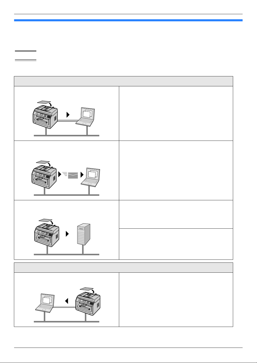
nScan features
Push scan
Scan to a computer You can scan the document from unit and then send it
to a computer. For details about this feature, see
"6.1 Scanning from the unit (Push Scan)" on
page 57.
Scan to email address (LAN supported models
only) (y)
Scan to FTP server/SMB folder (LAN supported
models only) (y)
Scanning from a computer You can scan the document from a computer (Pull
You can send the document as an attached file to an
email destination directly from the unit (page 57). To
activate this feature, see "Activating scan to email
address (LAN supported models only) (y)" on
page 58.
Scan to FTP server:
You can send the scanned document to an FTP server.
To activate this feature, see "Setting the information for
scan to FTP server (LAN supported models only)
(y)" on page 59.
Scan to SMB folder:
You can send the scanned document to an SMB folder.
To activate this feature, see "Setting the information for
scan to SMB folder (LAN supported models only)
(y)" on page 59.
Pull scan
scan). For details about this feature, see "6.2 Scanning
from a computer (Pull Scan)" on page 60.
4
Feature Highlights
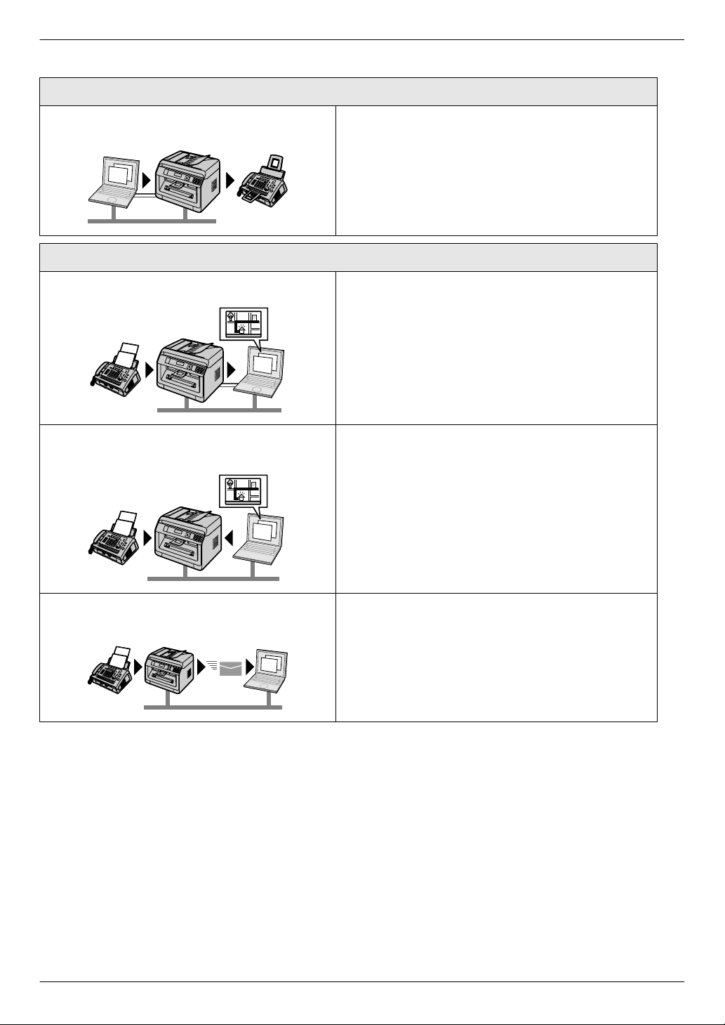
nFax features (y)
Sending faxes
PC fax sending You can send an electronic document as a fax message
from your computer. For details about this feature, see
“8.6.1 Sending an electronic document as a fax
message from your computer (PC fax sending)” on
page 82.
Receiving faxes
PC fax reception You can receive a fax document on your computer. For
details about this feature, see "8.6.2 Receiving a fax on
your computer (PC fax reception)" on page 82.
Web fax preview (LAN supported models only)
(y)
Fax to email address (LAN supported models
only) (y)
You can display a received fax document in a web
browser without printing, and print or save the
necessary document after you confirm the image. For
details about this feature, see "8.6.3 Web fax preview
(LAN supported models only) y" on page 83.
You can automatically transfer a received fax document
(fax to email feature) to one or more email addresses.
For details about this feature, see "8.6.4 Transferring
faxes to email address (LAN supported models only)
y" on page 84.
5
A
CB
A
Important Information
For your safety (emergency processing method)
Laser radiation
CLASS 1 LASER PRODUCT
R The printer of this unit utilises a laser. Use of
controls or adjustments or performance of
procedures other than those specified herein may
result in hazardous radiation exposure.
Laser diode properties
Laser output : Max. 10 mW
Wavelength : 760 nm - 800 nm
Emission duration : Continuous
Note:
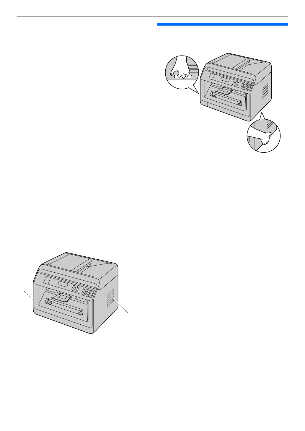
R The area near the rear cover (C) may also get warm.
This is normal.
LED light
CLASS 1 LED PRODUCT
R When using the unit, do not look directly at the
CIS’s LED light. Direct eye exposure can cause
eye damage.
CIS’s LED light properties
LED radiation output : Max. 1 mW
Wavelength :
Red : 624 nm typical
Green : 525 nm typical
Blue : 470 nm typical
Emission duration : Continuous
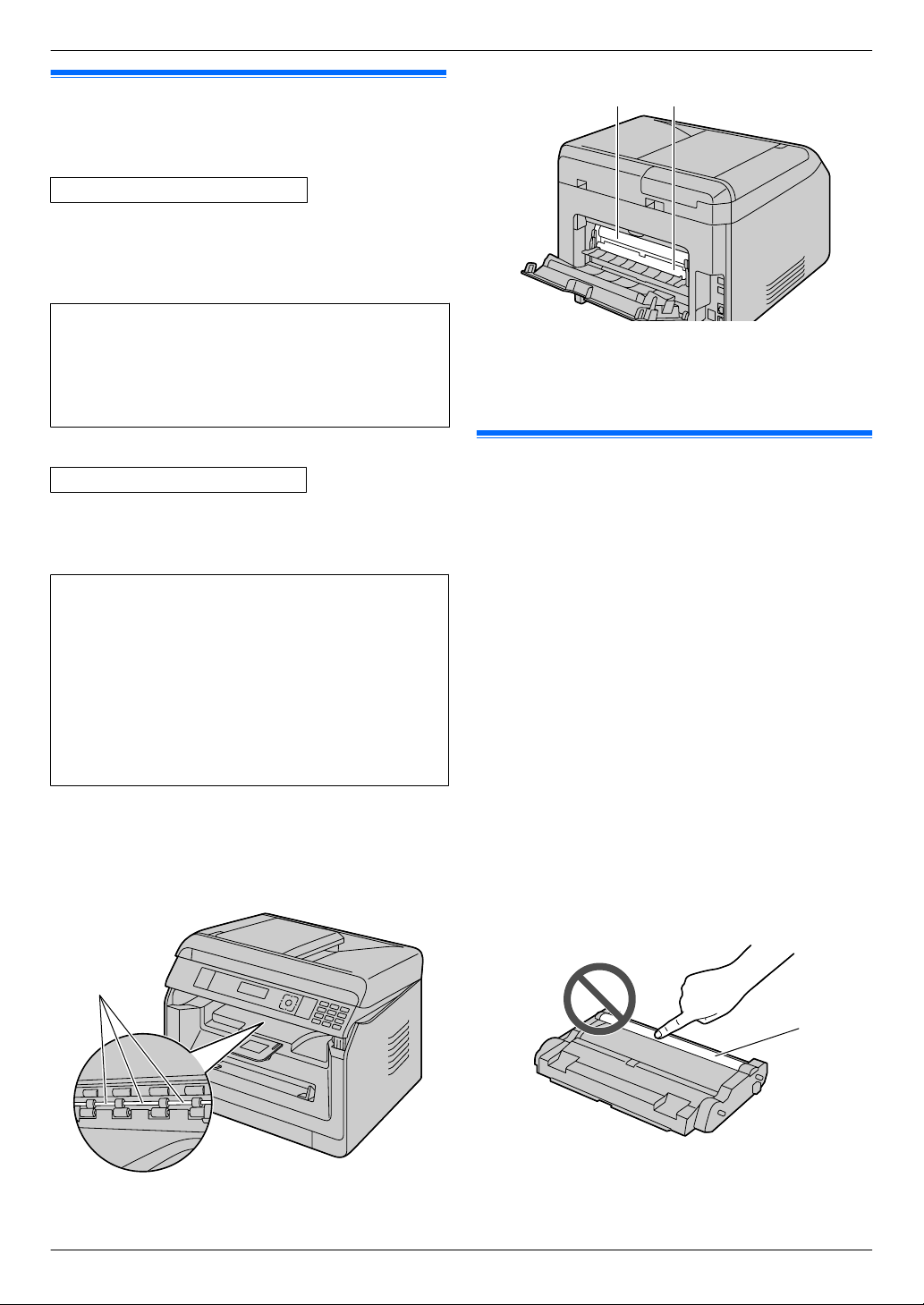
Recording paper exit rollers and fuser unit
During or immediately after printing, near the
R
recording paper exit roller shaft (A) and fuser unit
(B) gets hot. This is normal. Do not touch it.
For best performance
Toner cartridge and drum cartridge
R When replacing the toner cartridge or drum cartridge,
do not allow dust, water, or liquids to come in contact
with the drum. This may affect print quality.
R Genuine Panasonic toner cartridges and drum
cartridges are recommended.
R It is recommended not to add non-genuine toner to
the unit (including toner cartridge, drum cartridge
etc.).
R We cannot be responsible for problems that may be
caused by a non-Panasonic toner cartridge or drum
cartridge:
– Damage to the unit
– Poor print quality
– Improper operation
R Do not leave the toner cartridge out of the protective
bag for a long time. It will affect the printing quality.
R The drum cartridge contains a photosensitive drum.
Exposing it to light may damage the drum.
– Do not expose the drum cartridge to light for more
than 5 minutes.
– Do not touch or scratch the drum surface (A).
– Do not place the drum cartridge near dust or dirt,
or in a high humidity area.
– Do not expose the drum cartridge to direct
sunlight.
6
R To extend the life of the drum cartridge, the power
A
A
should never be turned OFF immediately after
printing. Leave the power turned ON for a minimum
of 30 minutes after printing.
Location
R To avoid malfunction, do not position the unit near
appliances such as TVs or speakers which generate
an intense magnetic field.
Static electricity
R To prevent static electricity damage to the interface
connectors or other electrical components inside the
unit, touch a grounded metal surface before touching
the components.
Environment
R Keep the unit away from electrical noise generating
devices, such as fluorescent lamps and motors.
R The unit should be kept free from dust, high
temperature and vibration.
R The unit should not be exposed to direct sunlight.
R Do not place heavy objects on top of the unit. When
you leave the unit unused for a long period of time,
unplug this unit from the power outlet.
R The unit should be kept away from heat sources such
as heaters, kitchen stoves, etc. Damp basements
should also be avoided.
R Do not poke the unit with a sharp object such as a
pen. The area around the display is especially
smooth and sensitive to scratches or rips in the
smooth sheet.
R Do not cover slots or openings on the unit. Inspect
the air circulation vents regularly and remove any
dust build-up with a vacuum cleaner (A).
Important Information
Moving the unit
When moving the unit, carry it as shown.
Routine care
R Wipe the outer surface of the unit with a soft cloth. Do
not use benzine, thinner, or any abrasive powder.
7

Table of Contents
1. Introduction
Accessories
1.1 Checking the supplied accessories .............10
Finding the Controls
1.2 Overview .....................................................12
1.3 Button descriptions ......................................15
2. Installation and Preparation
Installation
2.1 Drum cartridge ............................................17
2.2 Output tray ..................................................18
Connections and Setup
2.3 Connections ................................................19
2.4 Turning the power ON/OFF .........................20
Initial Programming
2.5 Date and time (Fax or LAN supported models
only) y .......................................................21
Configuring the Network Access
2.6 Configuring the unit to access the LAN
y ...............................................................21
2.7 Wireless LAN settings y ...........................21
Installing Software
2.8 Required computer environment .................22
2.9 Installing software (including printer, scanner
and other drivers) ........................................22
3. Basic Operations
Operating the Unit’s Panel
3.1 Operating the unit’s panel ...........................25
Recording Paper and Documents
3.2 Loading recording paper .............................25
3.3 Setting documents ......................................32
Multi-Function Station
3.4 Multi-Function Station .................................35
Programming the Unit
3.5 Programming the unit from the operation
panel ...........................................................38
3.6 Programming features: Basic ......................38
3.7 Programming through a web browser (LAN
supported models only) y .........................41
Status of the Unit
3.8 Status of the unit .........................................43
5. Printing
Printing from Your Computer
5.1 Printing from Windows applications ............50
5.2 Easy Print Utility ..........................................54
Printing Programs
5.3 Programming features: PC print ..................56
6. Scanning
Scanning from the Unit
6.1 Scanning from the unit (Push Scan) ...........57
Scanning from a Computer
6.2 Scanning from a computer (Pull
Scan) ...........................................................60
Scanning Programs
6.3 Programming features: Scan ......................61
7. Copying
Basic Copying Features
7.1 Making a copy .............................................63
More Copying Features
7.2 More copying features .................................64
Copying Programs
7.3 Programming features: Copy ......................73
8. Fax
Basic Fax Features (Sending)
8.1 Availability of the fax feature .......................74
8.2 Preparation for sending a fax ......................74
8.3 Basic procedure for sending a fax ...............74
Basic Fax Features (Receiving)
8.4 Preparation for receiving a fax ....................75
8.5 Basic features of receiving a fax .................76
Advanced Fax Features
8.6 Advanced Fax features ...............................82
Fax Programs
8.7 Programming features: Fax .........................86
9. Network
Network Programs
9.1 Availability of the network feature ...............90
9.2 Programming features: LAN ........................90
9.3 Network features .........................................92
4. Telephone Number and Email
Address
Character Entry
4.1 Character entry (Fax or LAN supported models
only) y .......................................................45
Storing, Editing and Erasing Items
4.2 Storing telephone number and email address
from your unit (Fax or LAN supported models
only) y .......................................................47
4.3 Registering items in the address book through
a web browser (LAN supported models only)
y ...............................................................49
8
10. Other Useful Features
Other Useful Features
10.1 Reference lists and reports .........................95
10.2 Mode restriction ...........................................96
10.3 QUICK-JOB feature ....................................97
10.4 Cloud print (LAN supported models only)
y ...............................................................98
10.5 Secure Print ................................................98
10.6 Talking to the other party after fax transmission
or reception y ...........................................99
10.7 Distinctive Ring service y .......................100

11. Help
Reports and Display
11.1 Report messages (Fax supported models only)
y .............................................................102
11.2 General messages ....................................102
11.3 Interface messages ...................................105
Troubleshooting
11.4 When a function does not work .................106
12. Paper Jams
Paper Jams
12.1 Recording paper jam .................................117
12.2 Document jams (Automatic document feeder)
y .............................................................120
13. Cleaning
Cleaning the Unit
13.1 Cleaning the white plates and glass ..........122
13.2 Cleaning the document feeder rollers
y .............................................................123
Cleaning the Cartridge
13.3 Cleaning the drum cartridge ......................123
Table of Contents
14. General Information
Specifications
14.1 Specifications ............................................125
Copyrights
14.2 Information of copyrights and licences (LAN
supported models only) y .......................132
15. Index
15.1 Index..........................................................133
9
1. Introduction
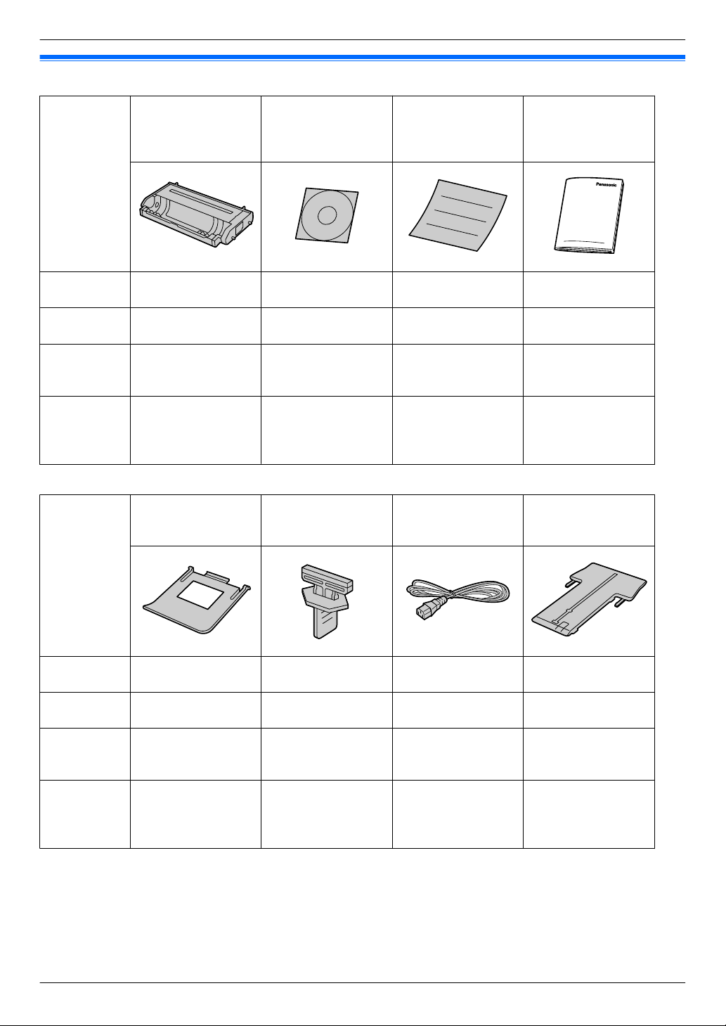
1.1 Checking the supplied accessories
1. . Introduction
A Drum cartridge
(pre-installed inside
the unit)(starter
B CD-ROM
(including driver for
printer etc.)
C Quick installation
guide
D Important
information guide
toner included*1)
Models
KX-MB2110
KX-MB2117
KX-MB2120
KX-MB2128
U U U U
U U U U
KX-MB2130
KX-MB2137
U U U U
KX-MB2138
KX-MB2168
KX-MB2170
KX-MB2177
U U U U
KX-MB2178
E Output tray F Drum cleaner
G Power cord
*3
H Extension guide
*4
(pre-installed inside
the unit)
*2
Models
KX-MB2110
KX-MB2117
KX-MB2120
KX-MB2128
KX-MB2130
KX-MB2137
KX-MB2138
KX-MB2168
KX-MB2170
KX-MB2177
KX-MB2178
U U U U
U U U U
U U U U
U U U U
10
1. Introduction
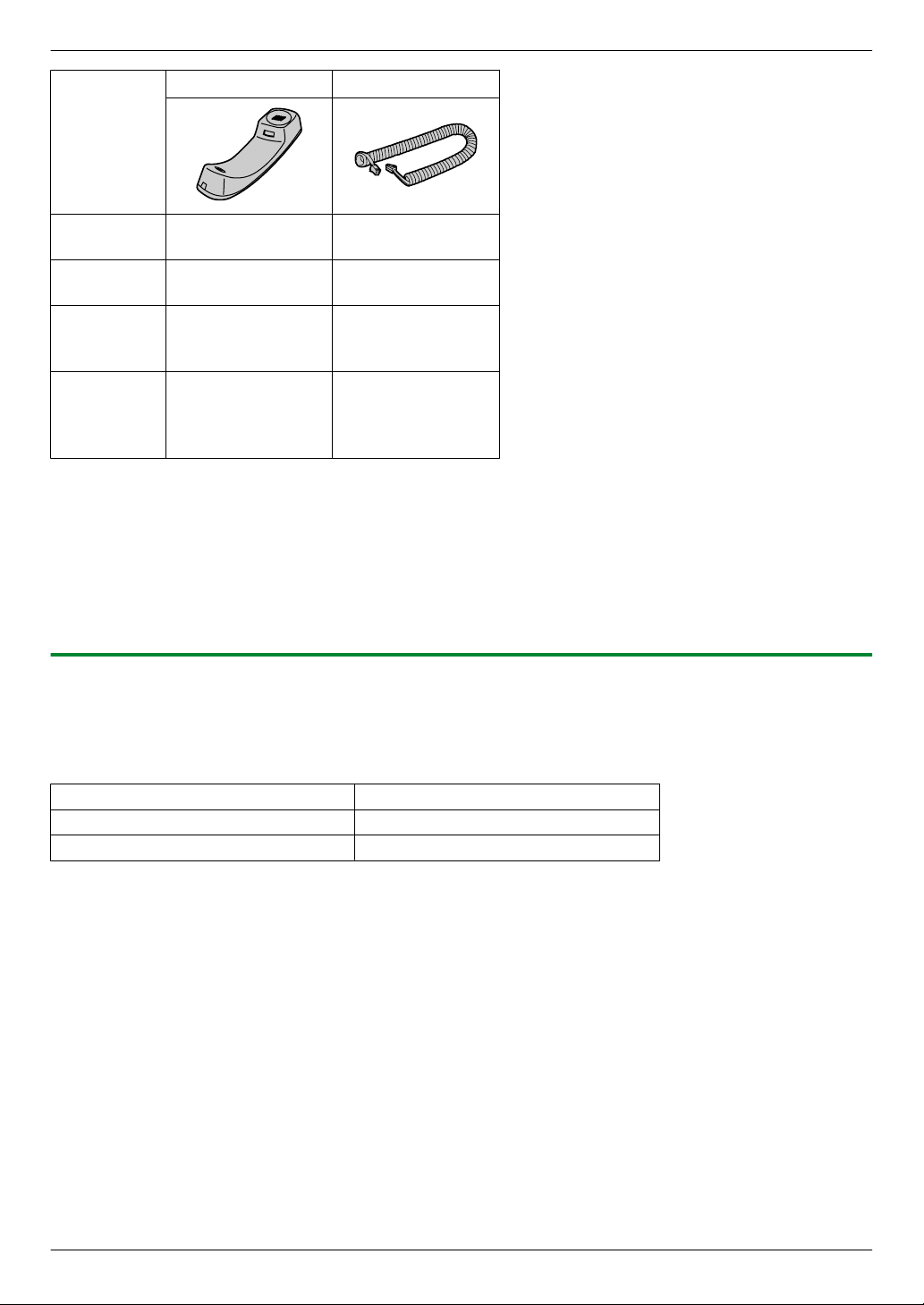
I Handset
Models
KX-MB2110
KX-MB2117
KX-MB2120
KX-MB2128
KX-MB2130
KX-MB2137
KX-MB2138
KX-MB2168
KX-MB2170
KX-MB2177
KX-MB2178
*1 Prints approximately 700 pages in accordance with ISO/IEC 19752 standard page.
*2 See page 123 for details.
*3 Use the supplied cord that is appropriate for where you use this unit.
*4 CX/SX/ML/LA/AG models only
*5 CX/HX/ML/RU/HK/TW models only
Note:
R Save the original carton and packing materials for future shipping and transportation of the unit.
R After unpacking the product, take care of the packing materials and/or power plug cap appropriately.
*5
– –
U U
U U
U U
J Handset cord
*5
1.1.1 Accessory information
n Replacement accessory
To ensure that the unit operates properly, we recommend the use of Panasonic toner and drum cartridges.
See the important information guide for details.
Accessory
Toner cartridge KX-FAT472
Drum cartridge KX-FAD473
Model No. (Part No.)
11

FECBA
I J KG H
D
1. Introduction
1.2 Overview
1.2.1 Front view
Parts
A ADF (Automatic Document Feeder) cover
B Output tray
C Document entrance
D Document guides
E Manual tray
F Document tray
G Standard input tray
H Recording paper guides
I Recording paper exit
J Document exit
K Document cover
12
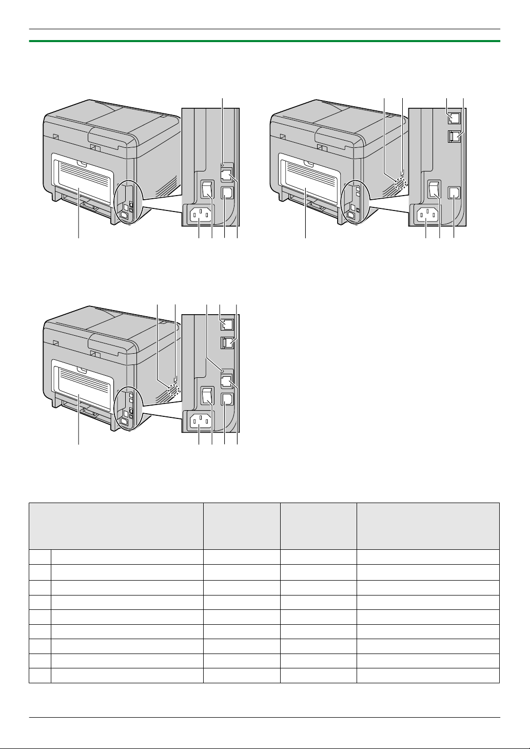
1.2.2 Rear view
GHIJ
C
F
GHI
A
DE
F
B
GHIJ
C
A
DE
F
B
n KX-MB2110/KX-MB2117 n KX-MB2120/KX-MB2128
n KX-MB2130/KX-MB2137/KX-MB2138/
KX-MB2168/KX-MB2170/KX-MB2177/KX-MB2178
1. Introduction
KX-MB2130/KX-MB2137/
Parts
A Speaker — U U
B Handset connection jack
C LED U — U
D Telephone line jack — U U
E External telephone line jack — U U
F Rear cover U U U
G Power inlet U U U
H Power switch U U U
I USB interface connector U U U
KX-MB2110/
KX-MB2117
—
KX-MB2120/
KX-MB2128
*1
U
KX-MB2138/KX-MB2168/
KX-MB2170/KX-MB2177/
KX-MB2178
U
*1
13

1. Introduction
KX-MB2130/KX-MB2137/
Parts
J LAN interface connector
R 10Base-T/100Base-TX
*1 Only for models that include a handset unit. See page 10 if your unit has a handset.
KX-MB2110/
KX-MB2117
U — U
KX-MB2120/
KX-MB2128
KX-MB2138/KX-MB2168/
KX-MB2170/KX-MB2177/
KX-MB2178
14
A C D E G
LKH JI N PO
F
B C D E G
LKH JI QM PON
F
1. Introduction
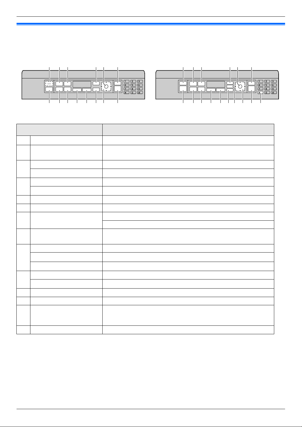
1.3 Button descriptions
n KX-MB2110/KX-MB2117 n KX-MB2120/KX-MB2128/KX-MB2130/KX-MB2137/
KX-MB2138/KX-MB2168/KX-MB2170/KX-MB2177/
KX-MB2178
Buttons Descriptions
A
For beep sounds
Mv/FAX AUTO
B
ANSWERN
Mm/QUALITYN To select the contrast and resolution when copying.
C
Md/QUALITYN
Mo/PAGE LAYOUTN To make copies using various page layouts.
D
Mz/CALLER IDN
*1
*2
*2
*3
E Mt/MENUN To start or exit programming.
F MOK/SETN To store a setting during programming.
G Mw/STOPN
Mh/SCANN/Mi/COPYN/Ml/
H
FAXN
*2
Mn/COPY SIZEN To select the copy size.
MT/REDIALN
I
MVN (Pause)
Mq/ZOOMN To enlarge or reduce a document when copying.
J
MR/FLASHN
*2
*2
*2
K Mr/DUPLEXN To make duplex copies.
L M[/QUICK-JOBN To use QUICK-JOB features.
M
Ms/MONITORN
*2
N M]/SECURE PRINTN To start printing secured documents.
Key beeps etc. will be heard.
To turn the auto answer setting ON/OFF.
To select the contrast and resolution when sending a fax.
To use Caller ID features.
To stop an operation or programming session.
To erase a character/number.
To switch to the scan mode, copy mode or fax mode.
To redial the last number dialled.
To insert a pause during dialling.
To access special telephone service or for transferring extension calls.
To initiate dialling. When you press Ms/MONITORN while receiving a call,
you will be able to hear the other party, but the other party will not be
able to hear you.
15
1. Introduction
Buttons Descriptions
To select desired settings.
To adjust the following volume*2:
Navigator key
O
MXN (Collate) To make a collate copy.
MWN (Address book)
*4
MWPSN
*2
P Mx/STARTN
Q MG/ToneN
– ringer volume (while setting the operation mode to fax mode)
– monitor volume (while using the monitor)
– handset volume (while using the handset)
To search for a stored item.
To connect easily to a wireless LAN.
To check the status of the wireless LAN connection.
To copy a document.
To scan a document (push scan).
To send a fax.
To change from pulse to tone temporarily during dialling when your line
has rotary/pulse service.
*5
*2
*1 Only for models without the fax feature. (
y)
*2 Only for models that support the fax feature. (y)
*3 Only for models that support the Caller ID feature. (y)
*4 Only for models that support wireless LAN. (y)
*5 See page 10 if your unit includes a handset.
What "(repeatedly)" means in these instructions
Example:
Mo/PAGE LAYOUTN (repeatedly): “PAGE LAYOUT”
Press the button repeatedly to display the indicated item.
16
A
A
A
A
2. Installation and Preparation
2.1 Drum cartridge
The supplied drum cartridge includes starter toner (toner
2. . Installation and Preparation
cartridge is not supplied).
R When using the unit for the first time, please use the
supplied drum cartridge.
Caution:
R Read the instructions before you begin
installation.
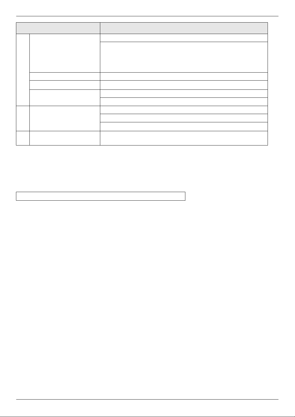
1 Open the front cover by holding the indentation (A).
R If the unit is in sleep mode, press a key to put the
unit in standby mode for the next process when
replacing the toner cartridge and/or drum
cartridge.
2 Remove the drum cartridge (A), which is
pre-installed in the unit.
3 Remove the protective sheet (A) from the drum
cartridge.
R Do not touch or scratch the drum surface.
R “PAPER JAMMED” is displayed before the
protective sheet is removed.
17

A
2. Installation and Preparation
4 Shake the drum cartridge horizontally more than 5
times.
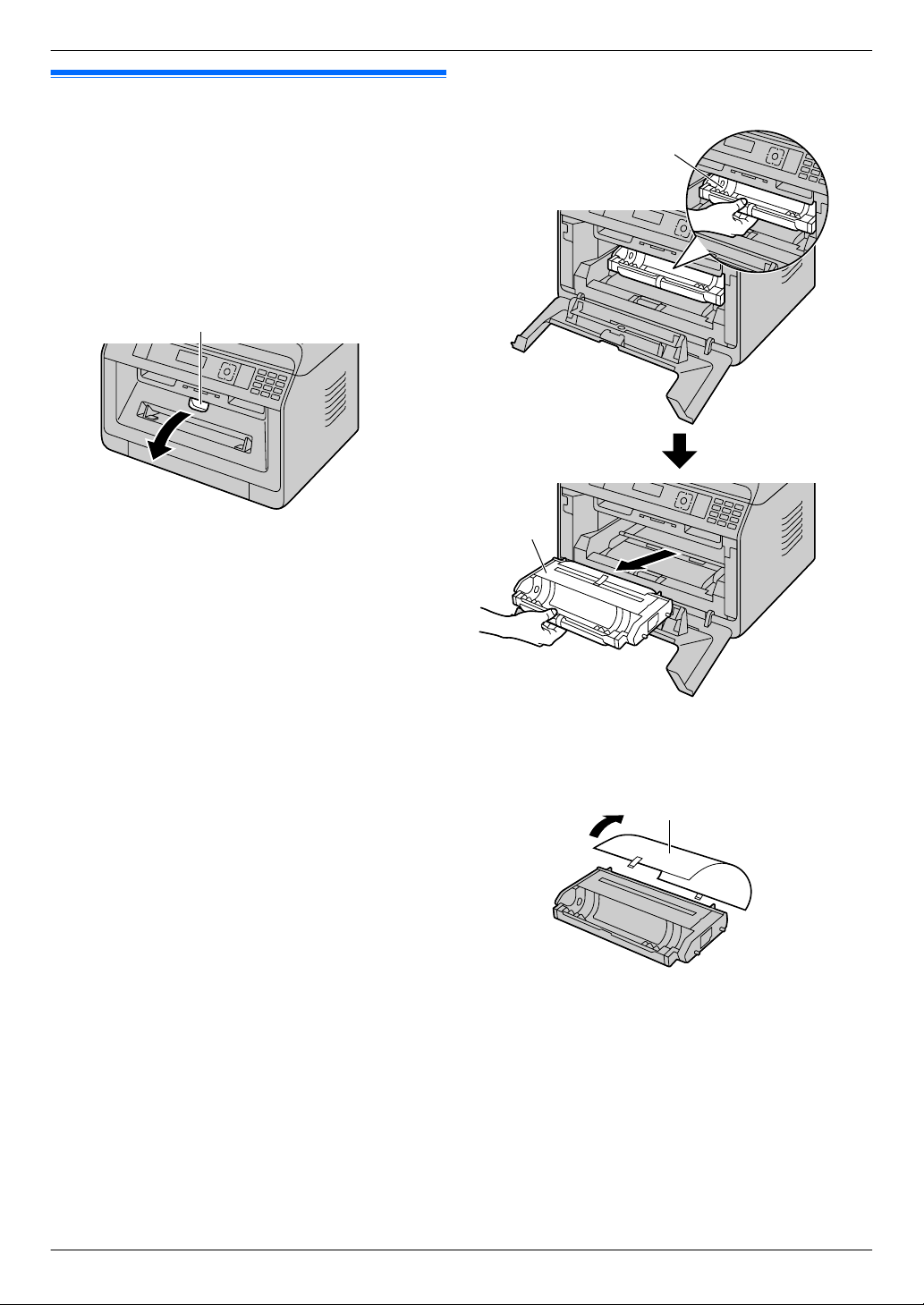
5 Hold the drum cartridge (A) by the centre handle,
then insert firmly to lock into place.
Toner save feature
If you want to reduce toner consumption, set the toner
save setting to ON (feature #482). The toner cartridge
will last approximately 20 % longer. This feature may
lower the print quality.
2.2 Output tray
The output tray supports the recording paper exit to hold
the printed paper.
1 Expand the paper exit.
6 Close the front cover.
Toner life and drum cartridge life
R To check the drum life and quality, please print the
printer test list (page 95) and refer to page 131 for
information on the drum life. If the printing quality is
still poor or “DRUM LIFE OVER” appears on the
display, replace the toner cartridge and drum
cartridge.
R To maintain print quality and machine life, we
recommend that you clean slots and openings
(page 7) and the inside of the unit (page 122, 123)
when replacing the toner cartridge and/or drum
cartridge.
Note:
R To ensure that the unit operates properly, we
recommend the use of Panasonic toner cartridge
and drum cartridge. See page 11 for accessory
information.
2 Insert the output tray.
18
A
A
DC
G
F
E
H
B
2. Installation and Preparation
3 Pull up the paper exit, and then replace the tab (A)
to the original position.
Note:
R The output tray may not be shown in all illustrations.
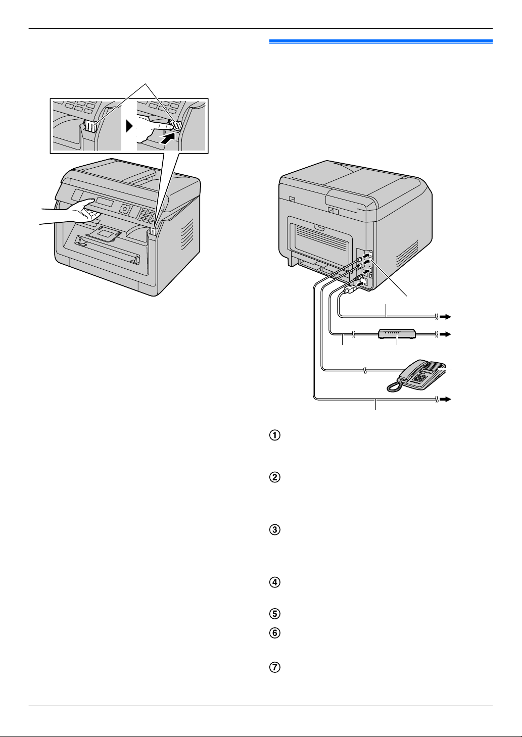
2.3 Connections
Caution:
R Never install telephone wiring during a lightning
storm (fax supported models only). (y)
R When you operate this product, the power outlet
should be near the product and easily accessible.
R Do not extend the telephone line cord (fax
supported models only). (y)
Power cord
R Connect to a power outlet. See page 125 for
detail specifications.
[EXT] jack
R You can connect an answering machine or an
extension telephone. Remove the stopper if
attached, and take care of it appropriately.
LAN cable (not supplied)
R To assure continued emission limit compliance,
use only shielded LAN cable (Category 5 (Cat-5)
Ethernet cable).
Network router/Network hub (not supplied)
R Also connect networked computers.
To the Internet
Extension telephone or answering machine (not
supplied)
Telephone line cord
R Connect to a single telephone line jack.
*1
*2
*3
*3
*3
*2
*2
19
2
5
4
3
1 a2
2 —
3 La
4 Lb
5 —
6 b2
61
A
2. Installation and Preparation
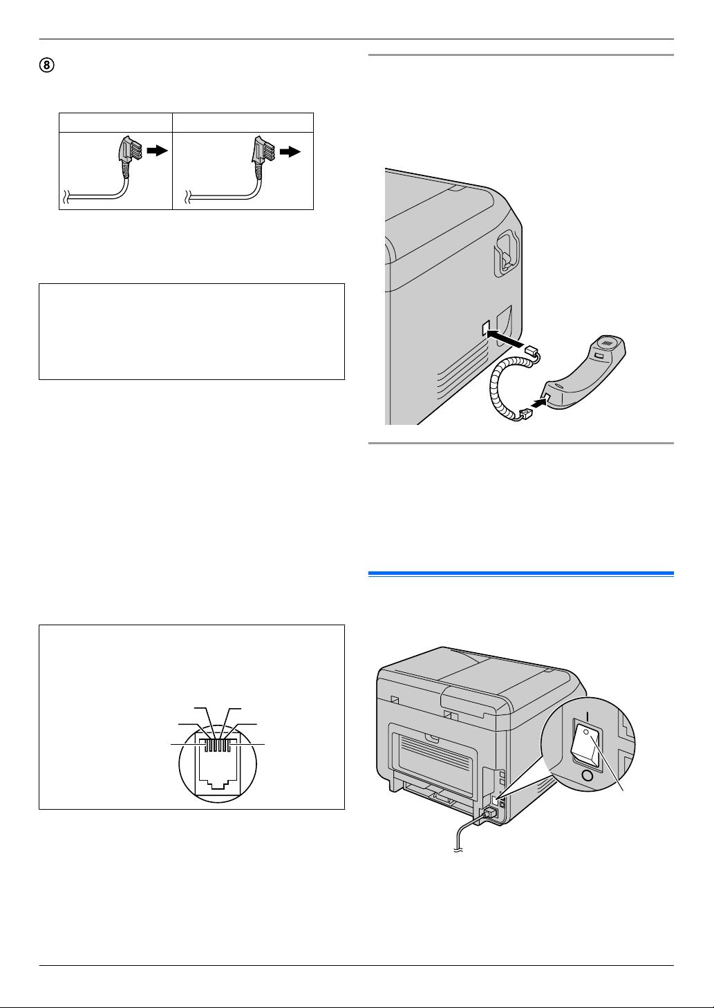
To a single telephone line jack
For users in Germany and Austria, use the
appropriate telephone line cord.
For Germany For Austria
*1 The power cord may differ slightly. Use the supplied
cord that is appropriate for where you use this unit.
*2 Fax supported models only (y)
*3 LAN supported models only (y)
IMPORTANT NOTICE FOR THE USB
CONNECTION
R DO NOT CONNECT THE UNIT TO A
COMPUTER WITH THE USB CABLE UNTIL
PROMPTED TO DO SO DURING THE SETUP
OF MULTI-FUNCTION STATION (page 22).
Note:
R An earthed contact jack should be used when
connecting the unit to the power outlet (for Poland
only).
R Do not place any objects within the following
distance:
– Right and left side: 10 cm
– Back side: 20 cm
R Do not cover slots and openings on the unit. They are
provided for ventilation and protection against
overheating.
R If another device is connected to the same telephone
line as this unit, you may experience unexpected
problems as this unit is not designed to share a
telephone line (fax supported models only). (y)
For Germany and Austria only:
Connector pinouts (fax supported models only)
(y)
Socket "To phone line"
Connecting the handset
See page 10 if your unit includes a handset.
Important:
R Before installing or removing the handset unit, be
sure to turn the power switch OFF.
Using network router/network hub (LAN supported
models only) (y)
R We recommend using network routers/network hubs
(D) under secure network environments. Consult
your network administrator for firewall settings, etc.
R The warranty does not cover damage due to security
problems or any inconveniences relating to it.
2.4 Turning the power ON/OFF
Turn the power switch to the ON position (A).
20

2. Installation and Preparation
2.5 Date and time (Fax or LAN supported models only) y
We recommend setting the date and time (feature #101).
The other party will receive your unit’s date and time as
the header information.
If you have subscribed to a Caller ID service (y)
The date and time will automatically set according to the
received caller information (feature #226).
2.6 Configuring the unit to access the LAN y
You can use a computer connected to the LAN for some
features of this unit (printer, scanner, etc.). To enable
these features, you need to set the IP address, subnet
mask, and default gateway in the unit.
Important:
R Consult your network administrator when setting
the IP address, subnet mask, and default
gateway.
2.6.1 Setting up automatically with a DHCP server
If your network administrator manages the network with
a DHCP (Dynamic Host Configuration Protocol) server,
it will automatically assign an IP (Internet Protocol)
address, subnet mask, and default gateway to the unit.
1 After connecting the LAN cable to the unit and the
computer, turn the power switch ON.
R The IP address, subnet mask, and default
gateway will be set automatically.
2 Install Multi-Function Station on the computer that
you want to use it with. See page 22 for details.
Note:
R You can connect two or more units and assign IP
addresses automatically with a DHCP server, but we
recommend assigning static IP addresses manually
for each unit to avoid network access and
configuration troubles.
2.6.2 Setting up manually
When your network administrator does not manage the
network with a DHCP server, you need to assign an IP
address, subnet mask, and default gateway manually.
1 Mt/MENUN A MBNM5NM0NM0N A “DHCP”
2 M0N A “DISABLED” A MOK/SETN
3 Set each item.
For the IP address:
1. M5NM0NM1N A “IP ADDRESS” A MOK/SETN
2. Enter the IP address of the unit. A MOK/SETN
For the subnet mask:
1. M5NM0NM2N A “SUBNET MASK” A MOK/SETN
2. Enter the subnet mask of the network. A MOK/
SETN
For the default gateway:
1. M5NM0NM3N A “DEFAULT GATEWAY” A MOK/
SETN
2. Enter the default gateway of the network. A
MOK/SETN A Mt/MENUN
4 Install Multi-Function Station on the computer that
you want to use it with. See page 22 for details.
2.7 Wireless LAN settings y
Important:
R When configuring wireless LAN settings, confirm
that the unit is located within operational range
of your wireless access point.
R Depending on the type of wireless access point,
select the appropriate way to connect the unit
and access point.
– Access point is WPS compatible (with a WPS
button)
– Access point is WPS compatible (without a
WPS button)
– Access point is not WPS compatible
R It is also possible to configure wireless LAN
settings when installing the driver regardless of
the type of wireless access point or whether there
is a WPS button (page 22).
R For wireless security settings, refer to the
operating instructions of your wireless router
and other wireless products, etc.
2.7.1 WPS compatible access point (with a WPS button)
1 Press the WPS button on your wireless access point.
2 Press and hold MWPSN on the unit until
“CONNECTING.....” is displayed.
R Perform step 2 within 1 minute of performing step
1.
R “CONNECTING.....” blinks while connecting.
When the connection is complete,
“CONNECTED” will be displayed.
Note:
R To display the status of the wireless access point,
press MWPSN, then press MOK/SETN.
2.7.2 WPS compatible access point (without a WPS button)
Important:
R Make sure the LAN mode setting is set to
“WIRELESS” beforehand (feature #580).
21

2. Installation and Preparation
1 Mt/MENUN A MBNM5NM8NM3N A MOK/SETN
R The PIN code of the unit is displayed.
2 Register the PIN code to your wireless access point.
3 MOK/SETN
R Perform step 3 within 1 minute of performing step
2.
R “CONNECTING.....” blinks while connecting.
When the connection is complete,
“CONNECTED” will be displayed.
R If the unit enters standby mode during the
process, repeat from step 1 (the PIN code will be
renewed).
2.7.3 WPS incompatible access point
Important:
R Make sure the LAN mode setting is set to
“WIRELESS” beforehand (feature #580).
R The following setting information for your
wireless access point is required:
– Network name (SSID)
– Network key (WEP / WPA key)
– Connection type
– Network authentication type
– Data encryption type
*1
If your wireless access point is equipped with
several network keys, use only the first
network key (this unit is equipped with a
single network key).
R If your wireless access point is configured to not
show the network name (SSID), enter the network
name (SSID) manually (feature #585).
*1
1 Mt/MENUN A MBNM5NM8NM4N A MOK/SETN
2 MCDN: Display the desired network name (SSID).
A MOK/SETN
R Depending on the settings for your wireless
access point, it may be necessary to select
WEP64 or WEP128. Select the desired item, and
then press MOK/SETN.
3 Enter the network key. A MOK/SETN
R Depending on the settings for your wireless
access point, this step can be omitted if
encryption is not used.
R “CONNECTING.....” blinks while connecting.
When the connection is complete,
“CONNECTED” will be displayed.
Setting up your wireless access point manually
1. Mt/MENUN A MBNM5NM8NM5N A MOK/SETN
2. Enter the network name (SSID). A MOK/SETN
3. MCDN: Display the desired connection type. A MOK/
SETN
4. MCDN: Display the desired network authentication
type. A MOK/SETN
MCDN: Display the desired data encryption type. A
5.
MOK/SETN
6. Enter the network key. A MOK/SETN
R Depending on the settings for your wireless
access point, this step can be omitted if
encryption is not used.
R “CONNECTING.....” blinks while connecting.
When the connection is complete,
“CONNECTED” will be displayed.
2.7.4 Setting up using Windows® Installer
If you use a Windows computer, it is possible to configure
wireless LAN settings during the installation of
Multi-Function Station. For details, see “2.9 Installing
software (including printer, scanner and other drivers)”
(page 22).
2.8 Required computer environment
Important:
R When using Windows Server® 2008/Windows
Server 2012, only the printer driver can be
supported. Install the printer driver using the Add
Printer feature of Windows.
R With Mac OS X, only the printer driver, scanner
driver (TWAIN/ICA) and PC fax (transmission) are
supported. See the setup guide for Mac OS X for
details.
To use Multi-Function Station on your computer, the
following are required:
Operating System:
Windows XP/Windows Vista/Windows 7/Windows 8
CPU:
Complies with Operating System recommendations
RAM:
Complies with Operating System recommendations
Other Hardware:
CD-ROM drive
Hard disk drive with at least 600 MB of available space
Web browser (recommendation):
Windows Internet Explorer® 8/9
Windows Internet Explorer 10/11 (with compatible mode
recommended)
2.9 Installing software (including printer, scanner and other drivers)
Panasonic Multi-Function Station software enables the
unit to carry out the following functions:
– Printing on plain paper, thin and thick paper, labels
and envelope
22
A
2. Installation and Preparation
– Displaying the preview of the print image, changing
the page order, deleting pages, and changing the
print layout etc. before printing (Easy Print Utility)
– Scanning documents and converting an image into
text with OCR software (not supplied)
– Scanning from other applications for Microsoft
Windows that support TWAIN scanning and WIA
scanning (USB connection only)
– Storing, editing or erasing items in the address book
using your computer
– Programming the features using your computer
– Assigning a password and printing confidential or
sensitive documents (Secure Print)
– Sending, receiving fax documents using your
computer (Fax supported models only) (y)
R Install Multi-Function Station (CD-ROM) before
connecting the unit to a computer with the USB
cable. If the unit is connected to a computer with
the USB cable before installing Multi-Function
Station, the [Driver Software Installation]
dialogue box may appear. If this dialogue box
appears, click [Close].
R If you are also using KX-MB200/KX-MB700/
KX-FLB880 series, see page 116.
®
2.9.1 Preparing your computer and CD-ROM
1 Start Windows and exit all other applications.
2 Insert the supplied CD-ROM into your CD-ROM
drive.
R If the installation does not start automatically:
Click [Start] A [All Programs] A
[Accessories]. Choose [Run]. Type “D:\Install”
(where “D” is the drive letter of your CD-ROM
drive). Click [OK].
(If you are not sure what the drive letter is for your
CD-ROM drive, use Windows Explorer and look
for the CD-ROM drive.)
3 Select your connection.
R For USB connection/wired LAN connection, refer
to “2.9.2 USB connection/LAN connection”,
page 23.
R For wireless LAN connection (y), refer to
“2.9.3 Wireless LAN connection y”, page 23.
2.9.2 USB connection/LAN connection
1 [Easy Installation]
R The installation will start automatically.
2 When the setup program starts, follow the on-screen
instructions.
R Easy Print Utility and Device Monitor will also be
installed.
3 The [Connection Type] dialogue box appears.
For USB connection:
1. [Connect directly with a USB cable.] A
[Next]
R The [Connect Device] dialogue box will
appear.
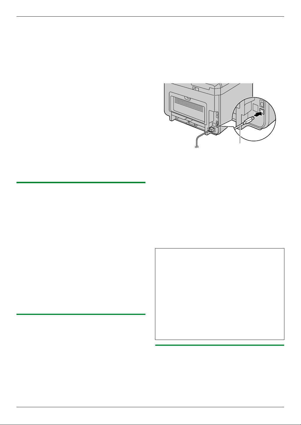
2. Connect the unit to a computer with the USB
cable (A), then click [Next].
3. Click [Install], then follow the on-screen
instructions.
For LAN connection (y):
1. [Connect via the Network.] A [Next]
2. Check [Select from the search list] and select
the unit from the list.
R If the name of the desired unit is not displayed
on the list, and the IP address for the unit has
been assigned, check [Direct input] and
enter the IP address.
3. [Next]
4. Click [Install], then follow the on-screen
instructions.
Important notice
When installing using a USB cable connection, a
message may appear during the software installation.
This is normal and the software will not cause any
difficulties with your operating system. You can
continue the installation with no problem. This kind of
message is displayed:
R For Windows XP users
“The software you are installing for this hardware
has not passed Windows Logo testing to verify its
compatibility with Windows XP.”
R For Windows Vista/Windows 7/Windows 8
users
“Would you like to install this device software?”
2.9.3 Wireless LAN connection y
Note:
R It is recommended to connect the unit to the wireless
network before installation.
For information about configuring wireless LAN
settings, please refer to "2.7 Wireless LAN settings
y", page 21.
23

2. Installation and Preparation
If the unit has already been connected to the wireless
network
1. [Easy Installation (Wireless LAN)]
2. Select [Already set up wireless LAN].
R The installation will start automatically.
3. When the setup program starts, follow the on-screen
instructions.
R Easy Print Utility and Device Monitor will also be
installed.
4. The [Select a Network Device] dialogue box
appears.
1. Check [Select from the search list] and select
the unit from the list.
R If the name of the desired unit is not displayed
on the list, and the IP address for the unit has
been assigned, check [Direct input] and
enter the IP address.
2. [Next]
3. Click [Install], then follow the on-screen
instructions.
If the unit has not been connected to the wireless
network yet
1. [Easy Installation (Wireless LAN)]
2. Select [Not yet set up wireless LAN].
R The installation will start automatically.
Important:
R The USB cable is required for configuring
wireless LAN settings. Wireless LAN settings
can be configured by using the wireless LAN
setting tool after installing it via USB
connection.
3. When the setup program starts, follow the on-screen
instructions.
R Easy Print Utility and Device Monitor will also be
installed.
4. The [Connect Device] dialogue box appears.
1. Connect the unit to a computer with the USB
cable, then click [Next].
R If the unit is connected to your computer, the
model name will be automatically detected.
2. Click [Install], then follow the on-screen
instructions.
5. When Wireless LAN Setting tool is launched, follow
the on-screen instructions to configure the wireless
LAN settings.
Click [Operating Instructions], then follow the
2.
on-screen instructions to view or install the operating
instructions in PDF format.
R Adobe® Reader® is required to view the operating
instructions.
Note:
R If you install the operating instructions, you can view
it anytime by clicking [Help] on the Multi-Function
Station launcher.
To use another unit with the computer
You need to add the printer driver for each unit, as
follows.
1. Start Windows and insert the supplied CD-ROM into
your CD-ROM drive.
2. [Modify] A [Add Multi-Function Station Driver].
Then follow the on-screen instructions.
Note:
R You cannot connect more than one unit to the same
computer at the same time (USB connection only).
To modify the software (To add or uninstall each
component)
You can select the components to install or uninstall
anytime after the installation.
1. Start Windows and insert the supplied CD-ROM into
your CD-ROM drive.
2. [Modify] A [Modify Utilities]. Then follow the
on-screen instructions.
To uninstall the software
[Start] A [All Programs] A [Panasonic] A the
unit’s name A [Uninstall]. Then follow the on-screen
instructions.
2.9.4 Other information
To view or install the operating instructions data
1. Start Windows and insert the supplied CD-ROM into
your CD-ROM drive.
24
3. Basic Operations
3.1 Operating the unit’s panel
3. . Basic Operations
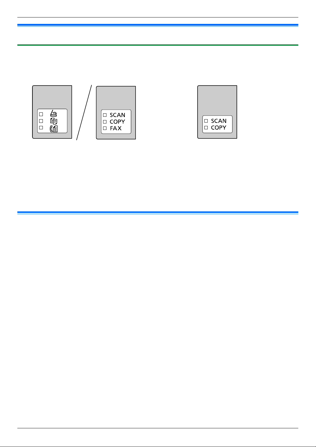
3.1.1 Selecting the operation mode
You can select the desired mode by pressing the following button repeatedly.
For models that support the fax feature (y) For models without the fax feature (y)
– Mh/SCANN: Select this mode when using the unit as a scanner.
– Mi/COPYN: Select this mode when using the unit as a copier.
– Ml/FAXN (y): Select this mode when using the unit as a fax machine.
Note:
R The default operation mode is the copy mode.
R You can change the default operation mode (feature #463) and the timer before returning to the default operation
mode (feature #464) (fax supported models only). (y)
3.2 Loading recording paper
Note for recording paper:
R We recommend that you test paper (especially special sizes and types of paper) on the unit before purchasing
large quantities.
R Do not use the following types of paper:
– Paper with cotton and/or fibre content that is over 20 %, such as letterhead paper or paper used for resumes
– Extremely smooth or shiny paper, or paper that is highly textured
– Coated, damaged or wrinkled paper
– Paper with foreign objects attached, such as tabs or staples
– Paper that has dust, lint or oil stains
– Paper that will melt, vaporize, discolour, scorch or emit dangerous fumes near 200 °C, such as vellum paper.
These materials may transfer onto the fusing roller and cause damage.
– Moist paper
– Inkjet paper
– Chemically treated paper such as carbon or carbonless duplicating paper
– Electrostatically charged paper
– Badly curled, creased or torn paper
– Paper with a coated surface
R Some paper is designed to be printed on only one side. Try printing on the other side of the paper if you are not
happy with the print quality, or if misfeeding occurs.
R For proper paper feeding and best print quality, we recommend using long-grained paper.
R Do not use paper of different types or thicknesses at the same time. This may cause paper jams.
R Do not re-use paper printed from this unit for another printing job (including other copiers or printers). This may
cause paper jams.
R To avoid curling, do not open paper packs until you are ready to use the paper. Store unused paper in the original
packaging, in a cool and dry location.
R For customers who live in high humidity areas: Please be sure to store paper in an air-conditioned room at all
times. If you print using moist paper, it may cause paper jam.
25
C
C
A
3. Basic Operations
To change the paper size and paper type
To use other paper sizes/types, see the following table and change the appropriate settings.
Tray type Paper sizes Paper types
Standard input tray feature #380 feature #383
Manual tray (y) feature #381 feature #384
R For number of sheets the unit can load, see page 128.
Tray number information
The unit shows the tray number as follows instead of displaying the name of tray.
– “#1”: Standard input tray
– “#2”: Manual tray (y)
3.2.1 Standard input tray
R If you load more than the specified amount of paper, a paper jam may occur and the paper may be damaged.
R Depending on the type of paper, the loaded paper may exceed the upper limit mark (
paper from the tray.
). In this case, remove some
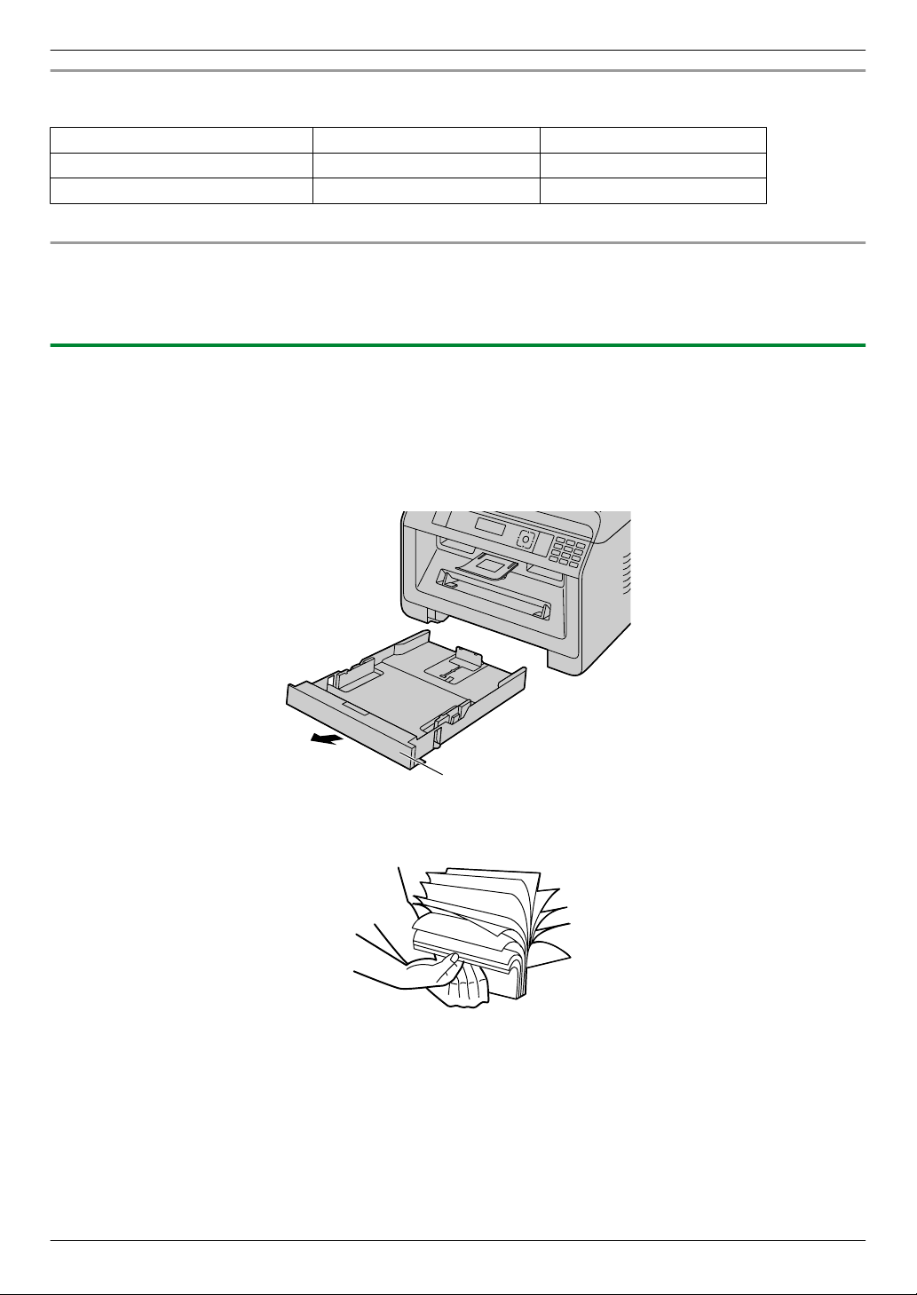
1 Pull the standard input tray (A) until it clicks into place, and then lift the front part of the tray and pull it completely
out.
2 Before loading a stack of paper, fan the paper to prevent paper jams.
26

3 Load the paper, print-side down (A).
A
B
A
B
Important:
R Push down to lock the plate (B) in the standard input tray, if necessary.
3. Basic Operations
R If necessary, slide the recording paper guides to
adjust the width to the size of the recording paper.
R Make sure that the recording paper is under the
paper limit mark (A), and the paper should not be
loaded over the snubbers (B).
4 Insert the standard input tray into the unit, lifting the front part of the tray. Then push it completely into the unit.
27
A
A
B
3. Basic Operations
Note:
R If the paper is not loaded correctly, re-adjust the paper guides, or the paper may jam.
R If the standard input tray does not close, the plate in the standard input tray may not be in the locked position.
Push the paper down and make sure that the paper is laying flat in the standard input tray.
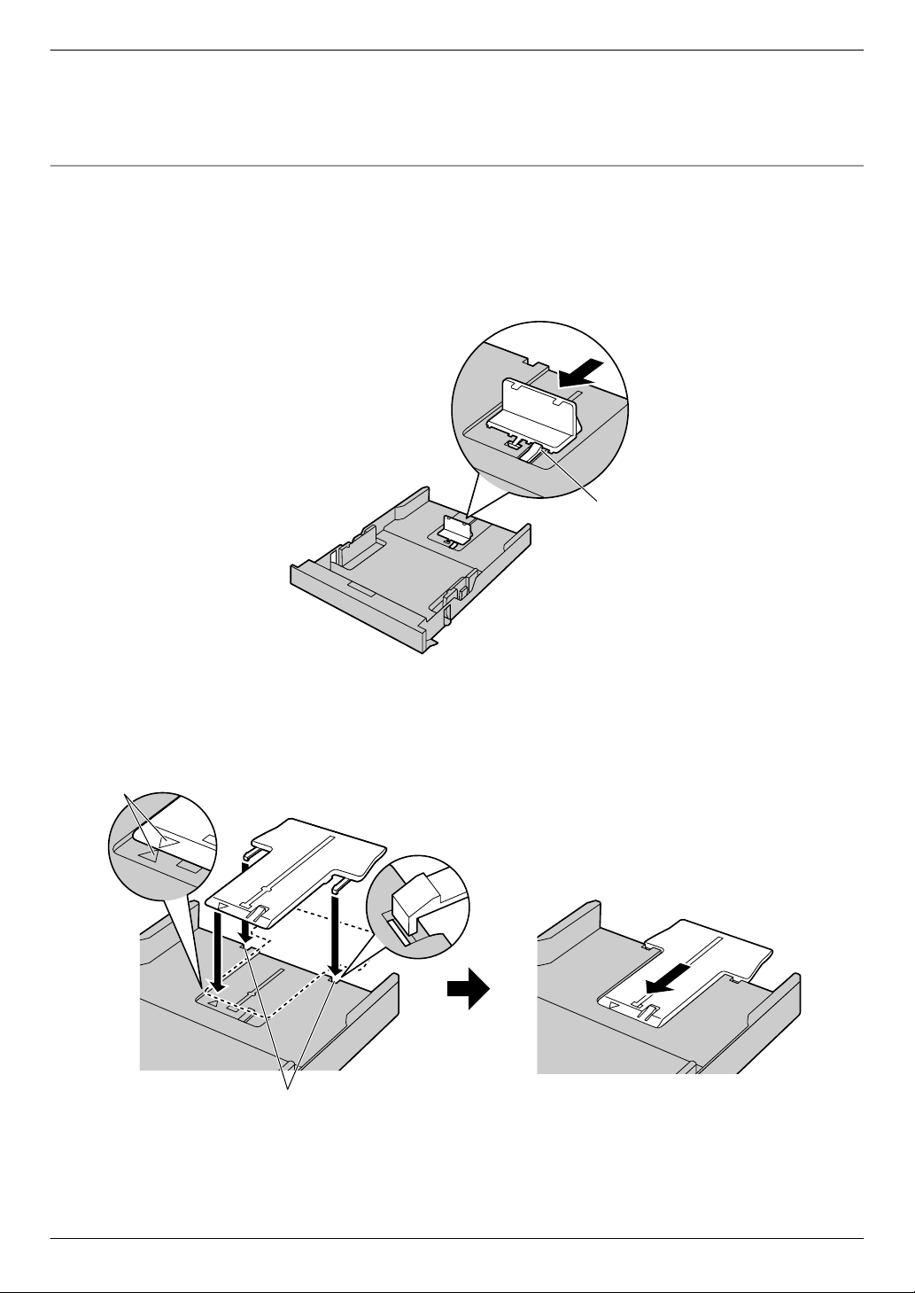
Loading paper larger than A4 size (using the extension guide)
When loading paper larger than A4 size, install the supplied extension guide beforehand. See page 10 if it is supplied
to your unit.
1. Remove the recording paper guide.
1. Pinch the rear guide, then slide it inside.
2. Push down the stopper (A), and then remove the guide completely.
2. Install the extension guide.
1. Insert the hooks of the extension guide into the small holes of the tray (A).
R Make sure the arrows (B) match, to install the extension guide correctly.
2. Slide the extension guide inside completely until it click into place.
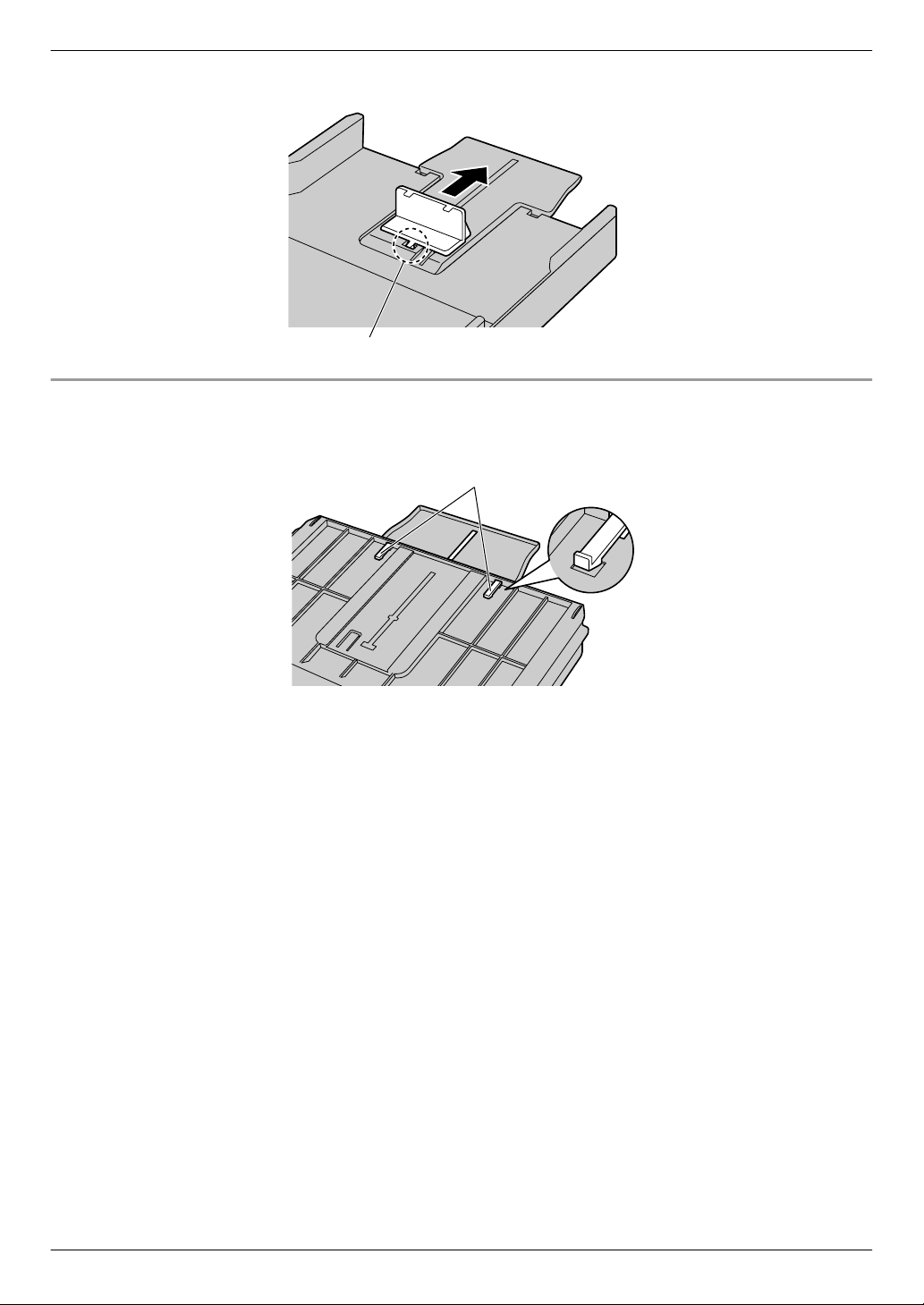
3. Re-insert the recording paper guide after installing the extension guide.
1. Re-insert the rear guide from the centre hole (A).
28
A
A
3. Basic Operations
2. Pinch the rear guide and then slide it back to the appropriate position.
To remove the extension guide
1. Remove the recording paper guide.
2. Release the hooks (A) from the bottom of the standard input tray to remove the extension guide.
3. After removing the extension guide, replace the recording paper guide.
29

Approx. 2 kg
3. Basic Operations
Caution for the standard input tray
R Do not drop the standard input tray. R Hold the standard input tray with both hands
when removing or installing. The standard
input tray weighs approximately 2 kg when
fully loaded with recording paper.
30
 Loading...