

Panasonic KX-HCM250 User Manual
Network Camera
Operating Instructions
Model No. KX-HCM250
Please read this manual before using and save this manual for future reference.
Panasonic Network Camera Site: http://www.panasonic.com/netcam
for customers in the USA or Puerto Rico

Operating Instructions
Introduction
Thank you for purchasing a Panasonic Network Camera.
Check the following items when unpacking.
Network Camera
Operating Instructions
Getting Started
AC Adaptor
Flexible Stand
Setup CD-ROM
Screws for Flexible Stand
For operation assistance:
•Call1-800-272-7033
• Refer to the Panasonic Network Camera Site
http://www.panasonic.com/netcam
—1pc.
—1pc.
—1pc.
—1pc.
—1pc.
—1pc.
—3pcs.
2

Operating Instructions
Trademarks
• Netscape and Netscape Navigator are either registered trademarks or
trademarks of Netscape Communications Corporation in the U.S. and other
countries.
• Adobe and Acrobat are either registered trademarks or trademarks of Adobe
Systems Incorporated in the United States and/or other countries.
• Ethernet is either a registered trademark or a trademark of Xerox Corporation
in the United States and/or other countries.
• Microsoft, Windows, Windows NT, MS-DOS, Hotmail and ActiveX are either
registered trademarks or trademarks of Microsoft Corporation in the United
States and/or other countries.
• Pentium is a trademark or registered trademark of Intel Corporation or its
subsidiaries in the United States and other countries.
• Screen shots reprinted with permission from Microsoft Corporation.
All other trademarks identified herein are the property of their respective owners.
Network Camera Memo
Attach your purchase receipt here.
For your future reference
Date of purchase
Serial Number
(Found on the rear side of the unit)
SSID (ESSID) Encryption Password
Name and address of dealer
MAC address
[For assistance, please call: 1-800-272-7033] 3

Operating Instructions
IMPORTANT SAFETY INSTRUCTIONS
When using this unit, basic safety precautions should always be followed to
reduce the risk of fire, electric shock, or personal injury.
1. Read and understand all instructions.
2. Keep these instructions.
3. Heed all warnings.
4. Follow all instructions.
5. After taking away the dust on the Fixed Focus Lens, wipe the Fixed Focus Lens
with lens cleaning paper.
6. Do not install near any heat sources such as radiators, heat registers, stoves,
or other devices (including amplifiers) that produce heat.
7. Protect the AC adaptor cord from being walked on or pinched particularly at
plugs, convenience receptacles, and the point where they exit from the unit.
8. Only use attachments/accessories such as stands, tripods, and brackets
specified by the manufacturer.
9. Do not touch the unit or the AC adaptor during lightning storms.
10.Unplug the unit when unused for long periods of time.
11.Refer all servicing to qualified service personnel. Servicing is required when
the unit has been damaged in any way, such as AC adaptor cord or plug is
damaged, the unit does not operate normally, or has been dropped.
SAVE THESE INSTRUCTIONS
4

Operating Instructions
Table of Contents
1 Product Introduction......................................................7
1.1 Getting to Know Network Camera .................................................... 8
1.1.1 Main Features............................................................................................. 8
1.1.2 System Requirements .............................................................................. 10
1.1.3 Authentication—System Security Feature ................................................ 11
1.2 Included Accessories...................................................................... 12
1.3 Camera Feature Locations ............................................................. 14
1.3.1 Front View................................................................................................. 14
1.3.2 Rear View ................................................................................................. 15
1.3.3 Bottom View.............................................................................................. 15
2 Network Camera Setup................................................16
2.1 Installation Procedure ..................................................................... 17
2.2 Network Camera Configuration Type.............................................. 18
2.3 How to turn on Network Camera for Installation ............................. 20
2.4 Network Parameters ....................................................................... 21
2.4.1 Preparing the Network Parameters for Network Camera ......................... 21
2.4.2 Setting IP Address of the PC in [Type 4] Configuration Type.................... 24
2.5 Proxy Server Setting....................................................................... 26
2.6 Simple Installation using the Setup CD-ROM................................. 28
2.7 Wireless Setup ............................................................................... 32
2.8 Network Camera Access from the Internet..................................... 37
3 Network Camera Screen and Setup Window.............39
3.1 Network Camera Flow Chart .......................................................... 40
3.2 Top Page......................................................................................... 41
3.3 Single Camera Screen ................................................................... 44
3.3.1 Using Operation Bar ................................................................................. 46
3.3.2 Using Pan/Tilt Operation........................................................................... 47
3.3.3 Setting Preset Positioning and Home Positioning.....................................48
3.3.4 Viewing Buffered Image Screen ...............................................................50
3.4 Multi-Camera Screen...................................................................... 52
3.5 Setup Page..................................................................................... 53
3.5.1 Go to Top Page......................................................................................... 57
3.5.2 Network..................................................................................................... 58
[For assistance, please call: 1-800-272-7033] 5

Operating Instructions
3.5.3 Name/Time................................................................................................62
3.5.4 Security: Administrator..............................................................................64
3.5.5 Security: General User..............................................................................66
3.5.6 Top View Image.........................................................................................68
3.5.7 Image Transfer ..........................................................................................70
3.5.8 Camera Setup ...........................................................................................82
3.5.9 Multi-Camera.............................................................................................85
3.5.10 External Output Control...........................................................................87
3.5.11 Indicator Control......................................................................................88
3.5.12 Status ......................................................................................................89
3.5.13 Restart.....................................................................................................90
3.5.14 Update Firmware.....................................................................................91
3.5.15 Reset to Factory Default..........................................................................94
4 Technical Guides ......................................................... 95
4.1 Network Camera Installation........................................................... 96
4.1.1 Network Camera Mounting........................................................................97
4.2 Interfacing to the External I/O....................................................... 102
4.3 ASCII and ISO-8859-1 Character Table ....................................... 104
4.4 Maintenance ................................................................................. 106
5 Specifications and Troubleshooting........................ 107
5.1 Network Camera Reset Procedure—Default Settings.................. 108
5.2 Default Settings List...................................................................... 109
5.3 Specifications ............................................................................... 115
5.4 Troubleshooting ............................................................................ 117
5.5 Confirmation of Network Camera Operation ................................ 123
5.6 FCC and Other Information .......................................................... 125
5.7 Glossary ....................................................................................... 127
Index................................................................................. 129
6

Section 1
Product Introduction
Operating Instructions
[For assistance, please call: 1-800-272-7033] 7

Operating Instructions
1.1 Getting to Know Network Camera
1.1.1 Main Features
Wireless Communication
Network Camera corresponds to the wireless system based on IEEE 802.11b.
Wireless installation will play an increasing role in flexible mounting.
Communication via Ethernet
Encryption establish the security on the wireless network.
Easy installation
Setup CD-ROM simplifies the installation. Insert the Setup CD-ROM and autorun
program should start the application automatically. This program automatically
finds Network Camera on the network.
High-Speed Motion JPEG
Network Camera has an integrated web server. Motion JPEG displays up to 15
frames per second, if the network provides enough bandwidth. To conserve
bandwidth, JPEG - Regularly Refresh can be selected from Top Page. Image
Resolution, Image Quality, Refresh interval, Limit time of Continuous Motion
JPEG and On the Air time features can control the image field.
®
(10Base-T) cable is also available.
Remote Pan/Tilt
Pan/Tilt operation can move the lens 120° horizontally and 45° vertically. This
movable lens allows you to see the situation widely where the object is. Operation
bar has Preset Positioning and Home Positioning features to register fixed
positions. Clicking the preset buttons moves the lens to the preset positions you
want to view. Single Camera screen has Click to Center feature too. The object
on Single Camera screen can be centered by clicking on the image directly.
Multi-Camera Screen
Using Multi-Camera screen you can simultaneously view up to four Network
Cameras at various locations. Clicking on each Camera Name switches to the
Single Camera screen from the Multi-Camera screen.
8

Operating Instructions
Multi Client Access
NetworkCameraallowsupto30userstoviewMotionJPEGimage
simultaneously. Users can access the Top View Image screen (Single Camera/
Multi-Camera screen) from their own locations. Note that as the number of users
simultaneously connected to Network Camera increases, the overall motion
performance will decrease.
External I/O (Input/Output)
The external sensors/devices such as a door sensor can be connected via the
External Sensor Input. The external sensors/devices are customer provided.
The alarm/timer trigger can activate the Image Transfer feature, which can send
the images via e-mail or FTP (File Transfer Protocol).
External Device Control Output can send a signal to activate the external
devices such as a light around Network Camera.
Update Firmware
If new firmware is released, you can download the latest program from Network
Camera Technical Support Site. Installation is easy and fast. Refer to page 91 for
details.
Authentication
Authentication window requires you to enter the administrator/general user ID
and password. Password security can prevent unregistered users/intruders from
accessing your image from their web browsers. Refer to Section
1.1.3 Authentication—System Security Feature for details.
Multi-Language Display
Top Page, Single Camera screen and Multi-Camera screen can be displayed in
English (US), English (UK), French, German, Italian, Spanish or Japanese. All
Setup windows are also changed when selecting English (US), English (UK) or
Japanese.
[For assistance, please call: 1-800-272-7033] 9

Operating Instructions
1.1.2 System Requirements
The PC (Personal Computer) and the network must meet the following technical
specifications for Network Camera to work properly.
Item Description
Operating
System
Microsoft®Windows®95, Microsoft Windows 98/SE
Microsoft Windows 2000, Microsoft Windows Me
Microsoft Windows NT®4.0, Microsoft Windows XP
Network
Protocol
Wireless LAN
TCP/IP network protocol installed.
(HTTP, TCP, UDP, IP, DNS, ARP, ICMP)
IEEE 802.11b
Standard
Interface 10/100 Mbps Ethernet card for your network connection
1
Web browser*
Internet Explorer 5.0 or later/Netscape Navigator®4.7x.
(NotincludedontheSetupCD-ROM).
1
Network Camera image is not displayed correctly in the Netscape®v6.x.
*
Use Netscape Navigator v4.7x.
Refer to Panasonic Network Camera Site
http://www.panasonic.com/netcam for the latest information on web
browser.
Note
®
Pentium
II 300 MHz or greater CPU is recommended to prevent performance
degradation.
10
Operating Instructions
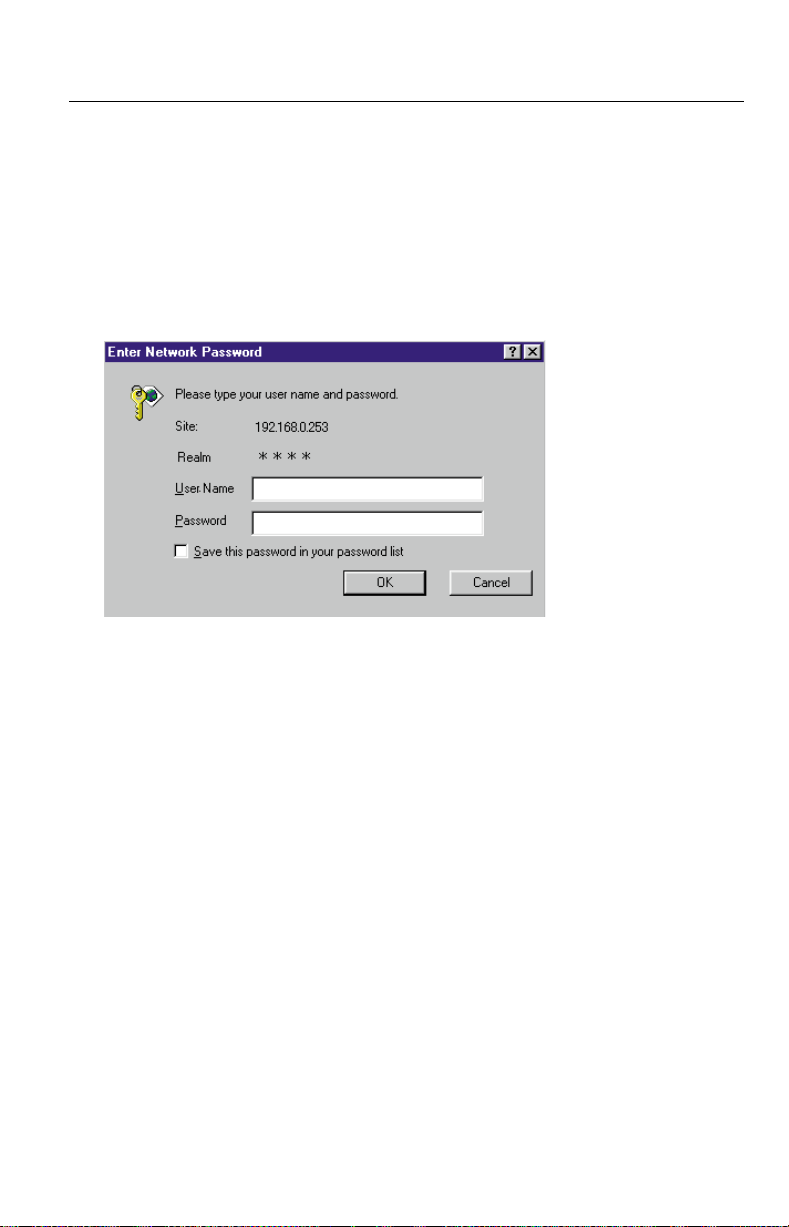
1.1.3 Authentication—System Security Feature
Authentication window requires you to enter the administrator/general user ID
and password for security. Password security can prevent unregistered users/
intruders from accessing your image from their web browsers. Authentication
windows are not displayed in the default. Refer to page 64 for setting up
Authentication window, the administrator ID and the password. Refer to page 66
for setting up the general user ID and the password.
Authentication window
[For assistance, please call: 1-800-272-7033] 11
Operating Instructions
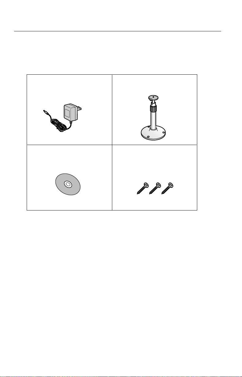
1.2 Included Accessories
The following items are provided with Network Camera. Additional pieces can be
ordered by calling 1-800-332-5368.
AC Adaptor — 1 pc.
Order No. PSLP1233Z
Setup CD-ROM — 1 pc.
Order No.
Notes
• If any items are missing, contact the dealer immediately.
• The order numbers listed above are subject to change without notice.
• Save the original carton and packing materials for future shipping and
PSQX2904ZCD
transportation of the unit.
Flexible Stand — 1 pc.
Order No. PSKL1020X
Screws for Flexible Stand
— 3 pcs.
Order No. PQHE5004Z
12

Operating Instructions
Setup CD-ROM
The setup program simplifies Network Camera installation. Adobe
®
Acrobat
Reader 4.05 or later enables you to see the Operating Instructions on the Setup
CD-ROM. If Adobe Acrobat Reader is not installed on the PC, double-click
"ar405eng.exe". Refer to "ReadmeEng.txt" for the directory and file structure of
the Setup CD-ROM.
Notes
• Do not scratch, smudge, write or label either surfaces of the Setup CDROM.SetupCD-ROMmayhaveascratchonthesurface.
• Do not leave the Setup CD-ROM in direct sunlight, near a heat source or
in a hot automobile as the Setup CD-ROM may become unreadable.
• Do not use chemicals or cleanser to clean the Setup CD-ROM as the Setup
CD-ROM may become unreadable.
®
[For assistance, please call: 1-800-272-7033] 13
Operating Instructions
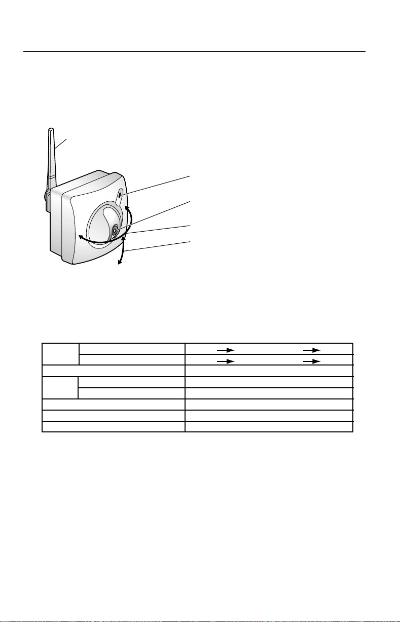
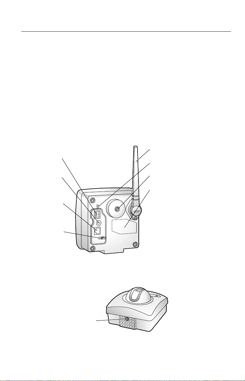
1.3 Camera Feature Locations
1.3.1 Front View
Antenna
Indicator
(Refer to page 88 for the setup.)
Fixed Focus Lens
1m(40inches)—Infinity
Pan: - 60° to + 60°
Tilt: 0° to - 45°
The field of view in Pan/Tilt ranges
horizontally about 165° and
vertically about 78°.
Indicator
Indicator can be controlled on Indicator Control window on page 88. Color
indications are shown below.
Powe r
on
Using
DHCP
Pushing CLEAR SETTING button Orange blinking twice
Internal Failure of Network Camera Red blinking*
1
*
Orange indicator will continue blinking in the DHCP setting.
2
Refer to page 119 for the red blinking.
*
Not on the LAN
On the LAN
Normal Operation
Getting IP address
Finish getting IP address
Updating Firmware
Orange OrangeOrange blinking*
Orange Green
Green blinking
Green
Green blinking
Green
Orange blinking
1
2
14
Operating Instructions
Fixed Focus Lens and Pan/Tilt operation
Fixed Focus Lens can move in the Pan/Tilt operation. Operation Bar on the Single
Camera screen can operate the Pan/Tilt. The Pan/Tilt moves the lens 120°
horizontally and 45° vertically. Refer to page 46 for the operation bar.
Notes
• Do not force to move the lens part around the Fixed Focus Lens.
Compulsive touching may damage the Pan/Tilt motor.
• Do not touch the Fixed Focus Lens. Touching it may leave a fingerprint and
can cause the image to be out of focus. This can also take away the
protective coating on the Fixed Focus Lens.
1.3.2 Rear View
Antenna
External I/O
(Refer to
page 102.)
DC IN jack
(Refer to
page 20.)
Ethernet port
(RJ-45)
(Refer to
page 20.)
Hook for AC
adaptor cord
(Refer to
page 97.)
(Refer to page 96.)
CLEAR SETTING button
(Refer to page 108.)
Mounting Hole for the various
mounting. (Refer to page 101.)
Serial Number and
MAC address
Record the serial number and
MAC address on Network
Camera Memo on page 3. They
are indispensable for setting
network parameters after
mounting Network Camera and
for future customer servicing.
(Refer to page 29.)
1.3.3 Bottom View
Tripod Mounting Hole
(Refer to page 99.)
[For assistance, please call: 1-800-272-7033] 15

Operating Instructions
Section 2
NetworkCameraSetup
16

Operating Instructions
2.1 Installation Procedure
Select the Network Camera configuration type. (Page 18—Page 19)
Connect Network Camera for installation. (Page 20)
Prepare the network parameters for Network Camera. (Page 21—Page 22)
Check the proxy server setting. (Page 26—Page 27)
Set up Network Camera with Setup CD-ROM. (Page 28—Page 31)
Setting up wireless network parameters. (Page 32 — Page 36)
Confirm the Network Camera Access from the Internet. (Page 37—Page 38)
Mount Network Camera. (Page 96—Page 101)
[For assistance, please call: 1-800-272-7033] 17
Operating Instructions
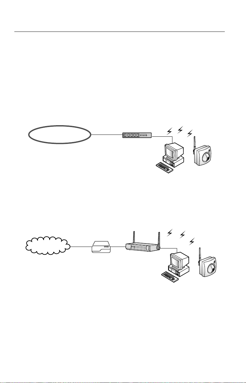
2.2 Network Camera Configuration Type
Network Camera can be connected over the LAN/Intranet and the Internet. Select
from the four Network Camera configuration types. Network parameters differ
depending on the Network Camera configuration type.
[Type 1]—LAN/Intranet Connection with an Ethernet
Switching Hub
Network Camera can be installed on the LAN/Intranet.
Ethernet switching hub*
or wireless access point
1
LAN/Intranet
1
*
Network traffic can be improved by using the Ethernet switching hub.
[Type 2]—Internet Connection with a Broadband Router
Network Camera can be accessed from the Internet. The broadband router needs
Port Forwarding (IP Masquerade) feature on page 37.
Wireless
Router
Internet
Modem
WAN LAN
CATV
xDSL
Optical cable
18

Operating Instructions
[Type 3]—Internet Direct Connection with a Modem
Network Camera can be installed alone without PC on the network. When you set
up Network Camera in [Typ e 3], connect Network Camera temporarily in [Type
1], [Type 2 ] or [Ty p e 4].
Modem
Internet
Note
Some xDSL services use PPPoE. Network Camera does not support PPPoE.
If the Internet connection requires PPPoE, connect with the broadband router
supporting PPPoE like [Type 2].
[Type 4]—Direct Connection with a PC
Network Camera can be connected to a PC directly.
Notes
• Use a category 5 cross cable when connecting directly with the cable
to a PC.
• Direct Connection with PC requires IEEE 802.11b wireless devices
such as wireless LAN card and wireless USB adaptor.
• Change to AdHoc mode. (Default is Infrastructure mode.) Refer to page
32 or Infrastructure and AdHoc mode.
[For assistance, please call: 1-800-272-7033] 19
Operating Instructions
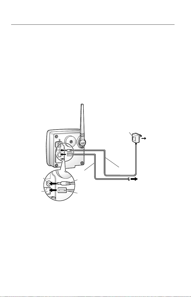
2.3 How to turn on Network Camera for
Installation
Network Camera is powered up when connecting AC plug to the power outlet.
1. Connect Category 5 straight/cross cable to the Ethernet port of Network
Camera to the hub or PC.
• Connect Ethernet cable first to make Network Camera recognize the wired
communication.
2. Connect the DC plug of the AC adaptor to the DC IN jack and the AC plug of
the AC adaptor to the power outlet to turn on Network Camera. Indicator blinks
and the Pan/Tilt moves to the center position.
AC adaptor
DC IN
jack
Ethernet
port
Notes
• AC adaptor is used as the main disconnect device, so ensure that the
power outlet is located/installed near the equipment and is easily
accessible.
• Use only the specified Panasonic AC adaptor PSLP1233 (Order No.
PSLP1233Z).
• When you set up Network Camera in [Type 3], connect it temporarily in
[Typ e 1], [Type 2] or [Ty pe 4].
• When Indicator is orange, ensure that the Ethernet cable is properly
connected, or PC, Ethernet hub or broadband router is properly working.
1.
DC Plug
Category 5 straight/cross cable
2.
Powe r
Outlet
To Network
20

Operating Instructions
2.4 Network Parameters
2.4.1 Preparing the Network Parameters for Network
Camera
Before starting to set up the network parameters of Network Camera, make note
of corresponding network parameters.
[Typ e 1] Ask your network administrator for the network parameters.
[Typ e 2] Refer to the broadband router’s manual for the network parameters.
[Typ e 3] Ask your ISP (Internet Service Provider) for the network parameters.
[Typ e 4] Install Network Camera in the default condition. Set the PC
"192.168.0.250" (IP address) and "255.255.255.0" (Subnet Mask).
Refer to page 24.
Refer to page 22 and page 23 for network parameters.
Network parameters memo for Network Camera
The devices on the network may not be assigned the same IP address. Each
device must have its own IP address. Overlapped IP addresses can cause other
network devices to stop working and may result in widespread network problems.
IP Address . . .
Subnet Mask . . .
Default Gateway
DNS Server 2 . . .
...
[For assistance, please call: 1-800-272-7033] 21
DNS Server 1 . . .

Operating Instructions
Network Parameters Table
Parameters
Port No.
IP address
Subnet
Mask
Default
Gateway
[Type 1] [Type 2] [Type 3] [Type 4]
80 (default) 80 (default)
Check [Static],
and set the
static private
IP address.
Set the Subnet Mask fitted to your network.
Set Default
Gateway
address.
Network Camera Configuration Type
80 (default)
*
*
Check [Static],
and set the
static private
IP address.*
3
Set the private
IP address of the
broadband router
1
80 (default)*
2
Check [Static],
and set the
static global
IP address.*
Set Default
Gateway
address.*
1
4
4
192.168.0.253
(default)
255.255.255.0
(default)
Youdonot
need to set up.
(on your network),
not of the gateway
of your ISP. *
DNS
Set DNS server address.
Server 1, 2
DDNS
Youdonot
need to setup.
Max.
Bandwidth
Usage
1
*
Many ISP's intentionally block port number 80 to guard against network
It can restrict the transmit bandwidth.
Select from 0.1 to Unlimited Mbit/s.
3
Set DNS server
address.*
5
*
4
5
*
Youdonot
need to setup.
viruses. If your ISP blocks port number 80, substitute it to another unused port
number.
2
When you use more than one Network Camera with a broadband router, each
*
Network Camera needs its own port number. The broadband router needs the
Port Forwarding feature. Refer to page 37.
3
Refer to the broadband router's manual for the Port Forwarding feature.
*
4
When you use Network Camera in DHCP feature, check [DHCP] and enter the
*
Host Name if your ISP requires. If you automatically get the address of Default
Gateway and DNS server from DHCP server, you do not need to set up.
5
Verify that your ISP supports DHCP. If your ISP supports DHCP, or if you
*
assign a domain name to Network Camera, you need to contract and register
for DDNS service. Refer to the included leaflet for DDNS service. If you set
static global IP address to Network Camera and the broadband router, you do
not need to register DDNS service.
22
Operating Instructions
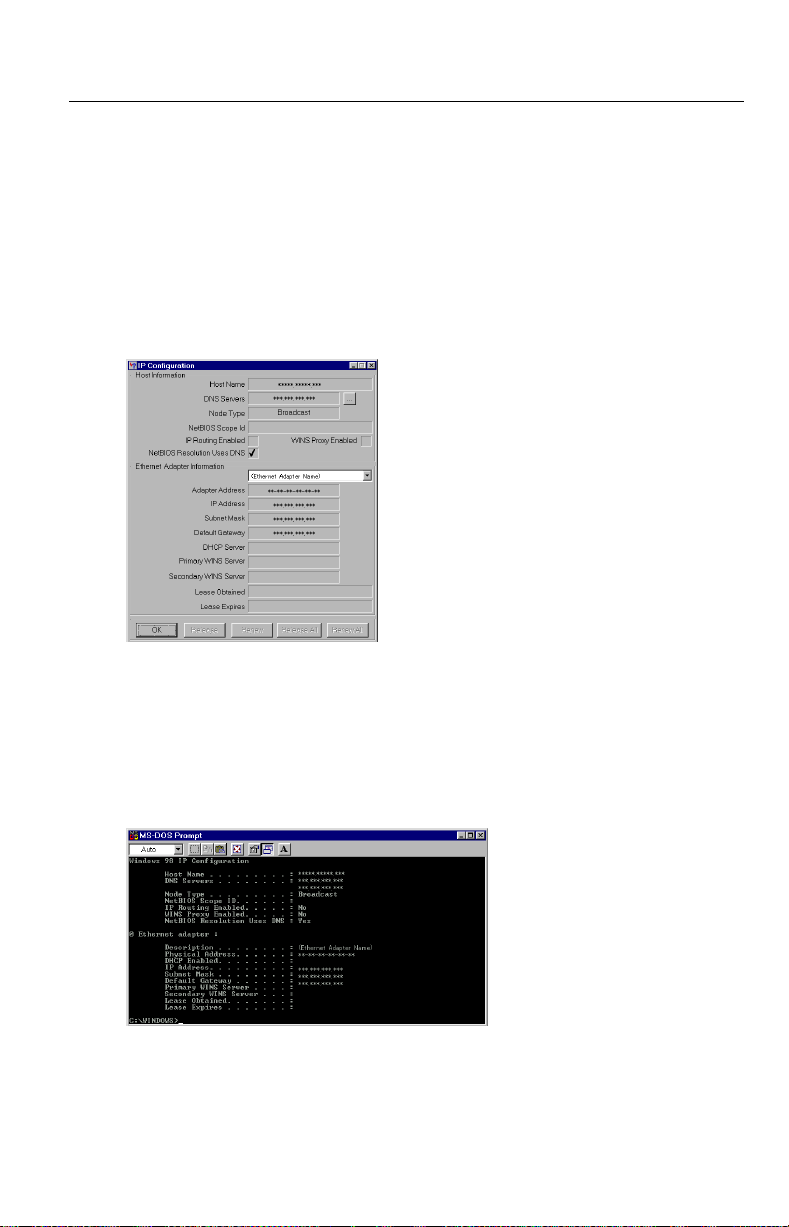
How to refer the network parameters from the PC
If you cannot get the network parameters, you can refer to the network parameters
except for IP address from the PC on the same network in the following procedure.
• When using Windows 95, Windows 98 or Windows Me
1. Click [Start] –> [Run...]. Run window appears.
These steps are slightly different depending on the operating system.
2. Enter "winipcfg"andclick[OK]. IP configuration window appears.
3. Select the proper Ethernet adaptor and click [More Info].
4. Click [OK] to close IP Configuration window.
• When using Windows NT, Windows 2000 or Windows XP
1. Click [Start] –> [Program] (–> [Accessories])–>[MS-DOS
Prompt]. MS-DOS Prompt window opens. These steps are slightly different
depending on the operating system.
®
(Command)
2. Enter "ipconfig /all" and press [Enter].
3. Enter "exit" and press [Enter] to close the window.
[For assistance, please call: 1-800-272-7033] 23

Operating Instructions
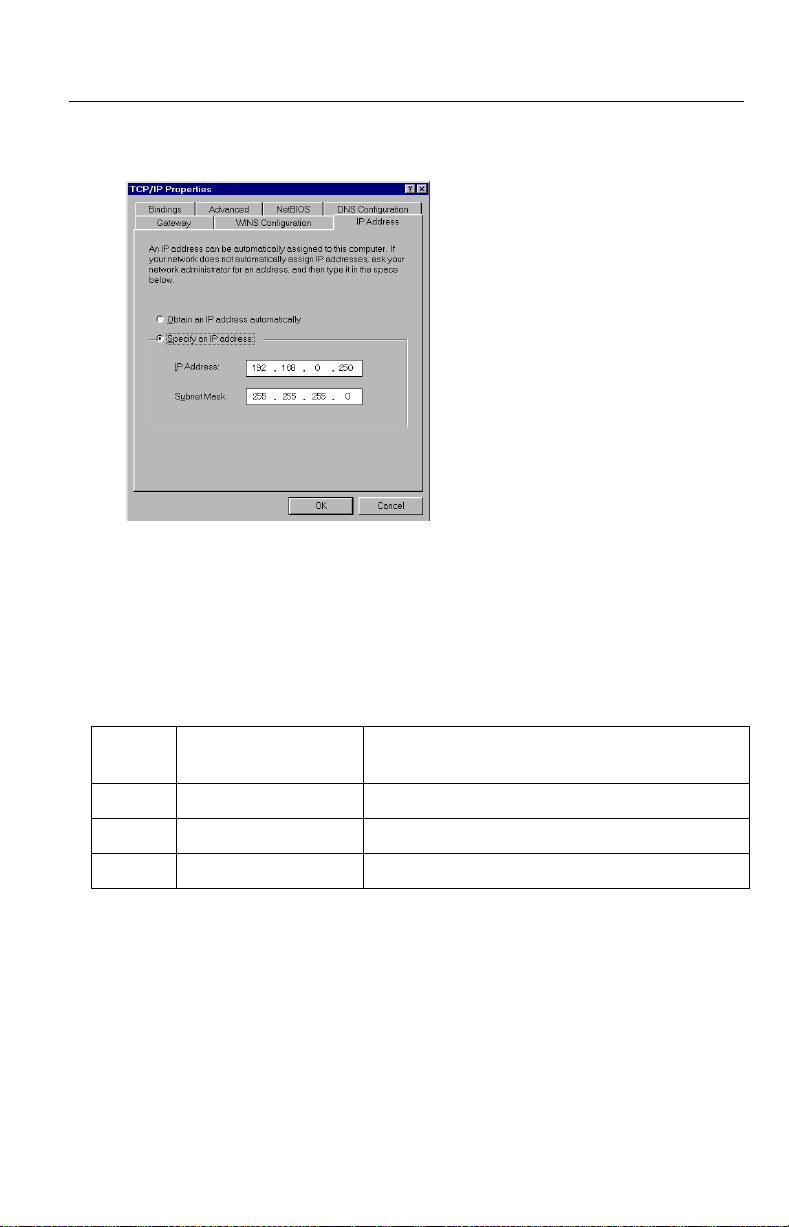
2.4.2 Setting IP Address of the PC in [Type 4]
Configuration Type
Your PC needs to have a static private IP address to access Network Camera in
[Type 4] configuration.
1. Follow the steps below, appropriate for your operating system to open TCP/IP
Properties window on the PC.
TCP/IP Properties Table
Operating
System
Windows 95
Windows 98
Windows Me
Windows NT [Start] –> [Settings] –> [Control Panel] –> [Network] –>
Windows
2000
Windows XP [Start] (–> [Settings])–>[Control Panel] –> [Network and
Note
When using Windows NT, Windows 2000 and Windows XP, log on as an
administrator to access TCP/IP Properties window.
[Start] –> [Settings] –> [Control Panel] –> [Network] –>
Select [TCP/IP] with adaptor in use –> [Properties] –>
[Specify an IP address]
[Protocols] tab –> [TCP/IP Protocol] –> [Properties] –>
Select [Adaptor] in use –> [Specify an IP address]
[Start] –> [Settings] –> [Control Panel] –> [Network and
Dial-up Connections] –> [Local Area Connection Icon] in
use –> [Properties] –> Select Internet Protocol [TCP/IP]
–> [Properties] –> [Use the following IP address]
Internet Connections] –> [Network Connections] –>
[Local Area Connection Icon] in use –> [Properties] –>
Select Internet Protocol [TCP/IP] –> [Properties] –> [Use
the following IP address]
Steps
24
Operating Instructions
2. TCP IP Properties window appears. Set "192.168.0.250" in the IP address
data field and "255.255.255.0" in the Subnet Mask data field.
3. Click [OK].
Private IP address
Private IP address is the network ID that is not used on the Internet. They are
classified into Class A, Class B and Class C, as shown in the next table. Set the
IP address in the range of the number specified in the class meeting to your local
network scale.
Class Subnet Mask
Class A 255. 0. 0. 0 10. 0. 0. 1 — 10. 255. 255. 254
Class B 255. 255. 0. 0 172. 16. 0. 1 — 172. 31. 255. 254
Class C 255. 255. 255. 0 192. 168. 0. 1 — 192. 168. 255. 254
[For assistance, please call: 1-800-272-7033] 25
Private IP address (It can be set freely within
the range in your group.)
Operating Instructions
2.5 Proxy Server Setting
A proxy server may prevent you from connecting directly to Network Camera in
some corporate environments. The web browser can set up the IP address
communication without using a proxy server. Consult your ISP or network
administrator.
Note
A proxy server is generally used to maintain security on a network that offers
an Internet connection. The network of Network Camera with the proxy server
may cause some problems to the image quality such as taking much time in
refresh interval. Consult your ISP or network administrator for details.
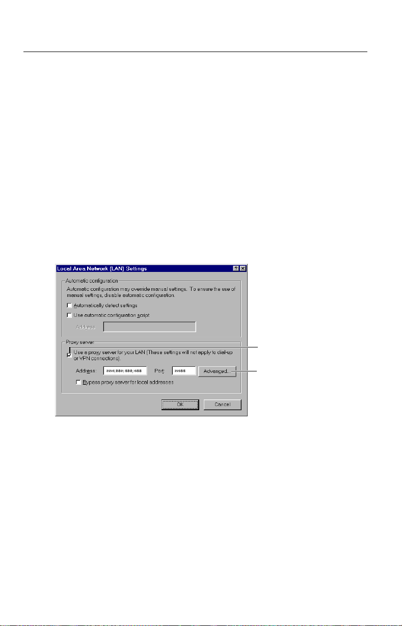
1. Start up the Internet Explorer. (The window is Internet Explorer 5.50.)
2. Select [Tools] –> [Internet Options...] –> [Connections] tab and click [LAN
Settings].SeeiftheUse a proxy server check box is checked or not in the
next window. When checked, click [Advanced...].
26
See if the check
box is checked or not.
When checked, click
[Advanced...].
When not checked, click [Cancel]. Your proxy settings are causing no
problems.
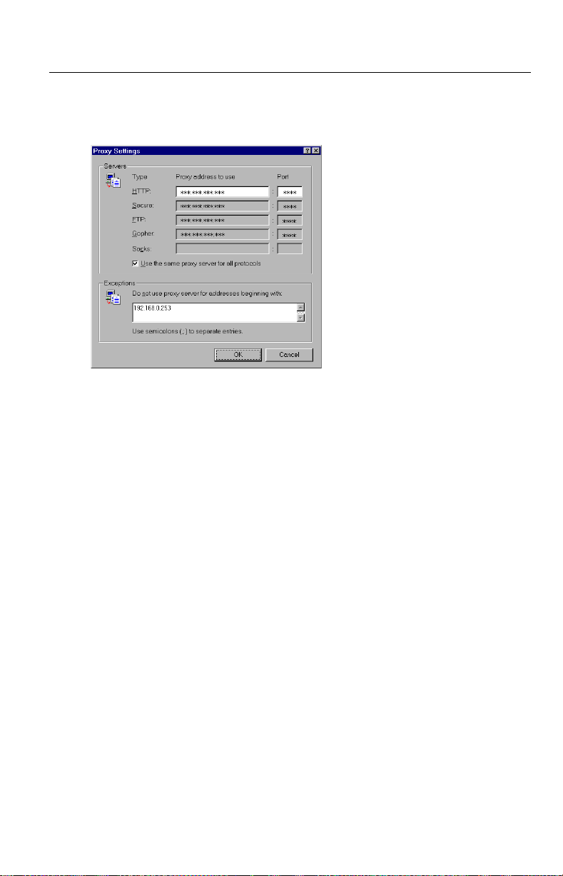
Operating Instructions
3. Enter the IP address of Network Camera assigned from your ISP or network
administrator into the Do not use proxy server for addresses beginning
with data field.
4. Click [OK] on all of the opening windows.
[For assistance, please call: 1-800-272-7033] 27
Operating Instructions
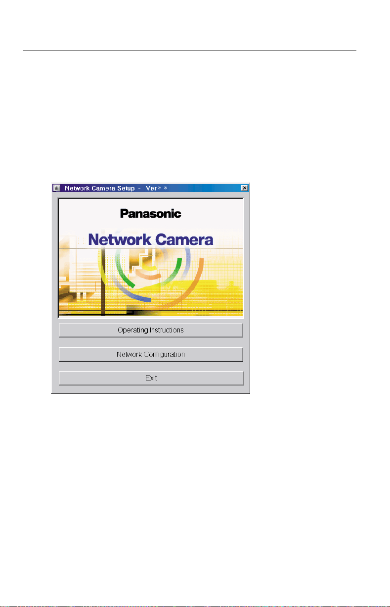
2.6 Simple Installation using the Setup CD-ROM
After finishing cabling, turn on Network Camera and insert the Setup CD-ROM in
the CD-ROM drive of the PC. Setup CD-ROM should start the application
automatically. This program automatically finds Network Cameras on the network.
1. Turn on Network Camera.
2. Insert the Setup CD-ROM in the CD-ROM drive of the PC.
(If Network Camera Setup window does not appear, click "setup.exe" on the
Setup CD-ROM.)
28
Operating Instructions
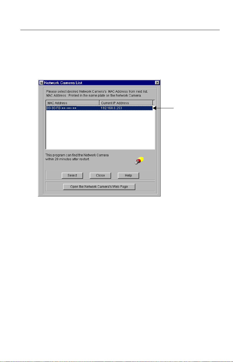
3. Click [Network Configuration]. Network Camera List window appears.
Setup program finds all Network Cameras connected on your local network. It
lists all of MAC addresses and IP addresses of Network Cameras. Network
Cameras that are isolated by the use of a home gateway or broadband router
will not be detected. Record MAC address on the Network Camera Memo on
page 3. It is useful for customer servicing.
(A)
Notes
• The setup program finds and identifies Network Camera by listening for
data, which Network Camera sends out for the first 20 minutes after
powering up. If the installation is not completed within 20 minutes,
disconnect temporarily the AC adaptor to restart this operation.
• Each Network Camera has a unique MAC address labeled on the back.
Refer to page 15.
• Network Cameras that are isolated by the use of a home gateway or
broadband router will not be detected.
[For assistance, please call: 1-800-272-7033] 29
Operating Instructions
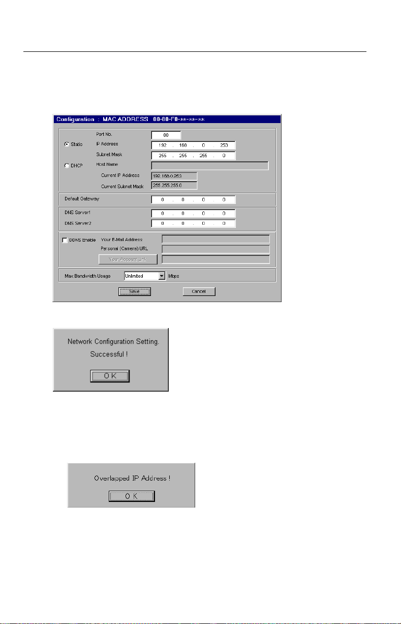
4. Select your target Network Camera from the list as shown in example (A) on
Network Camera List window onpage29andclick[Select]. Configuration
window appears. Refer to page 21 and page 22 and enter the correct network
parameters. Refer to page 59 for details of each parameter.
5. Click [Save] when finished. The "Successful!" message box appears.
30
Notes
• Network Camera automatically restarts after saving the network
configuration.
• Overlapped IP address displays the next box. If you cannot set up, ask your
ISP or the administrator.
 Loading...