

Panasonic KX-HCM110A User Manual
Operating Instructions
Network Camera
Model No.
KX-HCM110A
Please read this manual before using and save this manual for future reference.
Panasonic Network Camera Website: http://www.panasonic.com/netcam
for customers in the USA or Puerto Rico

Operating Instructions
Main Features
IPv6*1 Network Camera
Your Panasonic Network Camera supports IPv6 (Internet Protocol Version 6), IPv6
was created to address the additional IP addresses that will be needed as the
Internet continues to expand. Since the camera also supports IPv4 that's currently
used, it is "dual stack" design will seamlessly operate while IPv6 is phased in. For
more information in IPv6 you wish to visit http://www.ipv6.org/. See page
more information.
Audio 2-way Communication*2 (Walkie-talkie Type)
Your Panasonic Network Camera now provides 2-way audio, between the camera
and your PC. You will be able to hear the person on camera and respond using a
microphone connected to your PC's sound card (customer-provided.) They will
hear your response through the amplified speaker (customer-provided) connected
to the camera.
For example, the camera can be used in the following various locations:
• In the baby's room, to hear if the baby is crying.
• At the front door, to see and hear who is at the door.
• In the children's play room, to see and hear if they are safe.
Note
PLEASE NOTE that under certain circumstances, audio/video recording may
be PROHIBITED by law. This device should be used only in compliance with
all applicable federal, state and local statutes.
Digital zoom feature
Camera has a 10x digital zoom feature.
This feature allows you to increase or decrease the size of the object on the Single
Camera screen, the Multi Camera screen, and the Buffered Image screen.
Therefore, it will be easy to view the object that located to a distant place.
wheel operation and clicking the right mouse button increase or decrease the size
of the object on the Single Camera screen.
*3
*4
A mouse
15 for
*1
To connect in IPv6, subscribe to the ISP's "IPv4/IPv6 Dual-Stack" or "IPv6 over IPv4
Tunneling" service. The camera does not work in IPv6-only network.
*2
Audio feature does not work on cell phones. Talk button and Listen button cannot be used
simultaneously. In consequence of traffic and network environments, the audio may be
delayed or may break up.
*3
This feature is not available when viewing on a cell phone.
*4
As the magnification increases, the image quality decreases.
2

Operating Instructions
Various Camera Control Features
The camera pans or tilts fast in maximum 80 ° per second. You can control the
camera at high speed from your PC or cell phone. Alarm position feature also
allows the camera to automatically turn the lens to the alarm position. Additionally,
the following control features are available to easily and quickly monitor the
camera.
Click to Center ......... When you click a certain point on the camera image, the
point is centered on the image.
Preset Position ......... You can register 8 preset positions. When you click each
button, the image switches to its position.
Output Control ......... You can control the external devices (Open or Short to
GND) (E.g., turning the light on or ringing a buzzer).
Multi-Camera Support
Multi-Camera page displays up to 4 cameras while supporting each audio 2-way
communication. The previous model displays only 4 cameras, but this camera can
switch 3 sets of 4 cameras. Additionally, the camera can displays maximum 12
cameras on a page in a static image.
DynamicDNS Service Support
DynamicDNS service allows you to access the camera over the Internet with your
favorite domain name (e.g. bob.viewnetcam.com) instead of a global IP address.
Multi-Language Display
Top page, Single Camera and Multi-Camera page can be displayed in English,
French, German, Italian, Spanish, Russian, Simplified Chinese or Japanese. The
Setup, Maintenance and Support pages are displayed only in English or Japanese.
Motion Detection feature
Camera has a Motion Detection feature that detects movement, such as people,
based on the preset threshold and sensitivity of Camera.
You can buffer the camera images, transfer to an FTP server or send E-mails using
the Motion Detection function as a trigger.
[For assistance, please call: 1-800-272-7033] 3

Operating Instructions
How to Use This Documentation
The camera includes the following 4 manual types.
• Installation
Installation provides explanations for items included with the camera.
• Getting Started
Getting Started provides explanations for the initial configuration and the ways
of camera mount. The Getting Started helps you to easily configure the
camera.
• Operating Instructions (This manual)
Operating Instructions explains about operations, settings, features and the
cleaning method when using the camera.
• Troubleshooting
Troubleshooting provides explanations for troubleshooting tips.
Trademarks
• Adobe, Acrobat and Reader are either registered trademarks or trademarks of
Adobe Systems Incorporated in the United States and/or other countries.
• Microsoft, Windows, Hotmail and ActiveX are either registered trademarks or
trademarks of Microsoft Corporation in the United States and/or other
countries.
• Pentium is a trademark or registered trademark of Intel Corporation or its
subsidiaries in the United States and other countries.
• Screen shots reprinted with permission from Microsoft Corporation.
• All other trademarks identified herein are the property of their respective
owners.
• This software is based in part on the work of the Independent JPEG Group.
Abbreviations
• UPnP is the abbreviation for "Universal Plug and Play".
• "Network Camera" is called "Camera" in this Operating Instructions.
4

Operating Instructions
System Requirements for your PC
Your PC (Personal Computer) and network must meet the following technical
specifications for the camera to work properly.
For IPv4 Connection
Item Description
Operating
System
Microsoft® Windows® XP, Microsoft® Windows® 2000
Microsoft® Windows® Me, Microsoft® Windows® 98SE
CPU • For viewing single camera
Pentium® III (800 MHz or greater is recommended.)
• For viewing multiple cameras
Pentium 4 (1.8 GHz or greater is recommended.)
Protocol TCP/IP protocol (HTTP, TCP, UDP, IP, DNS, ARP, ICMP)
Interface 10/100 Mbps network card installed
Web Browser Internet Explorer 6.0 or later (Not included on the Setup CD-
ROM)
Audio Audio input/output feature (Microphone or speaker)
[For assistance, please call: 1-800-272-7033] 5

Operating Instructions
For IPv6 Connection
Item Description
Operating
Microsoft® Windows® XP Service Pack 1 or later
System
CPU • For viewing single camera
Pentium III (800 MHz or greater is recommended.)
• For viewing multiple cameras
Pentium 4 (1.8 GHz or greater is recommended.)
Protocol TCP/IP protocol (HTTP, TCP, UDP, IP, DNS, ICMPv6, NDP)
Interface 10/100 Mbps network card installed
Web Browser Internet Explorer 6.0 or later (Not included on the Setup CD-
ROM)
Audio Audio input/output feature (Microphone or speaker)
Note
See Panasonic Network Camera support website at
http://panasonic.co.jp/pcc/products/en/netwkcam/ for the latest
information about web browser.
6

Camera Feature Locations
Front View
Lens Cover
Lens (0.5 m [about 20 inches]—Unlimited)
Indicator
The indicator color shows camera status.
Microphone
The microphone picks up audio around the camera.
(See page 30)
Indicator Display
Powe r
on
Automatic
Setup
Using
DHCP
DEFAULT RESET button
Not on the LAN
On the LAN
Normal Operation*
Finished setting
Getting IP address*
Got IP address
Updating Firmware
Pressing FACTORY
TM
Failure Orange blinking (About a 2-second interval)
UPnP
Internal Failure Red blinking*
1
Setting
Orange blinking Green
2
Orange blinking
Green blinking
Orange blinking
Orange blinking Turning off
(The camera restarts after that.)
Operating Instructions
Green blinking
Green
Green blinking
Green
Green blinking
Green
3
*1 The indicator turns orange if the camera is not connected to the LAN.
*2 The indicator blinks orange if the camera is not connected to the LAN.
*3 See page 4 of the Troubleshooting on the Setup CD-ROM.
[For assistance, please call: 1-800-272-7033] 7
Operating Instructions
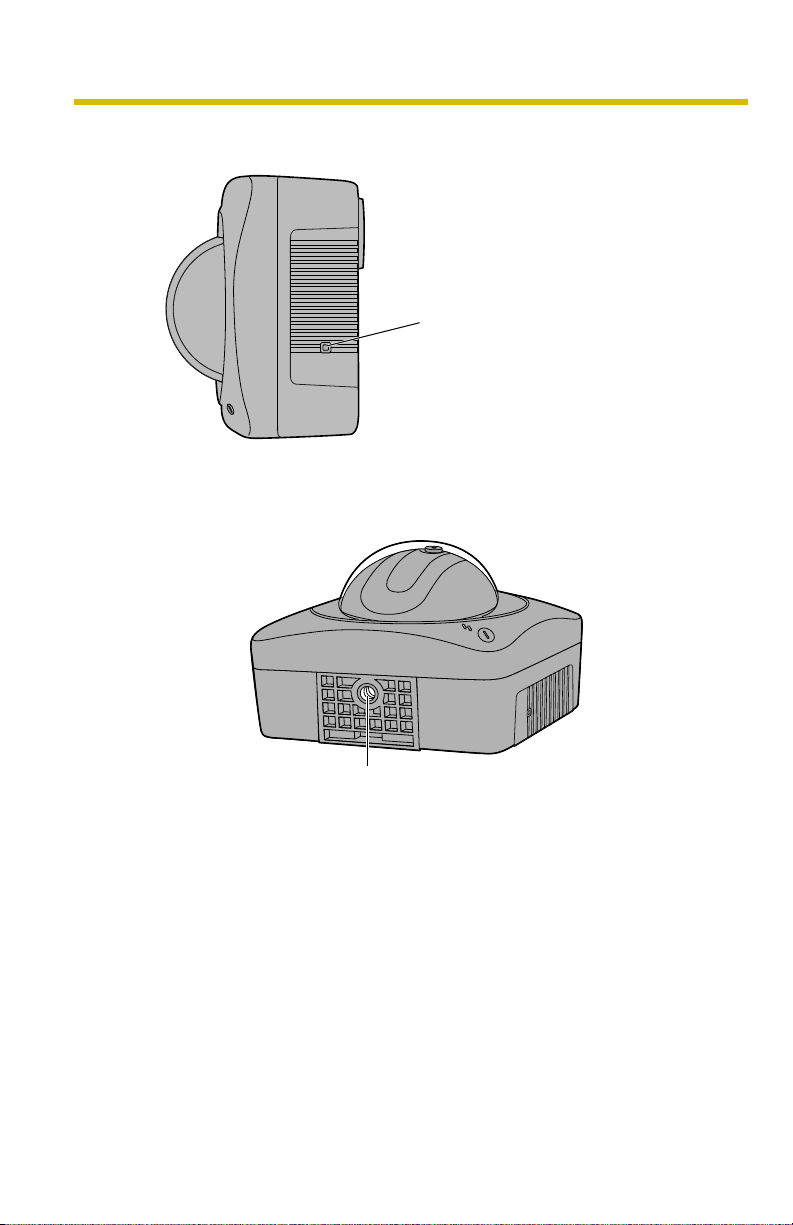
Side View
Bottom View
FACTORY DEFAULT RESET Button
Resets settings to default (see page
147).
Stand/Tripod Mounting Hole (See the Getting Started.)
8
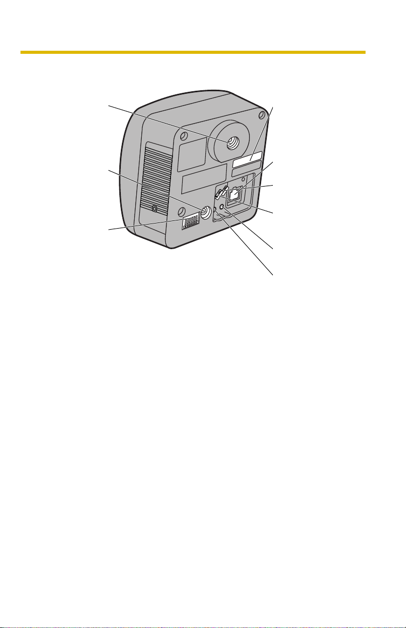
Rear View
Mounting Hole
DC IN jack
External I/O
(See page 145)
Stand
(See the
Getting
Started.)
(See the
Getting
Started.)
Operating Instructions
MAC Address
(See the Getting Started.)
and Serial number (S/N)
is indicated on the label.
Ethernet (LAN) port
(See the Getting Started.)
Hook for Audio Cables
(See the Getting Started.)
Hook for AC adaptor
Cord
(See the Getting Started.)
Audio Output Terminal
(See page 31)
External Microphone
Input Terminal
(See page 31)
[For assistance, please call: 1-800-272-7033] 9

Operating Instructions
Table of Contents
1 Camera Monitoring .....................................................13
1.1 Accessing the Camera ................................................................. 13
1.1.1 To Access the Camera in IPv6................................................................. 15
1.2 Viewing Single Camera page....................................................... 17
1.2.1 Auto Centering the Image (Click to Center)............................................. 21
1.2.2 Capturing a Still Image ............................................................................ 22
1.2.3 Using Operation Bar ................................................................................ 23
1.2.4 Zooming In and Out ................................................................................. 25
1.2.5 Setting Home Position/Alarm Position/Preset Button .............................. 26
1.3 Listening to Camera Audio—Talking to the Camera .................... 30
1.4 Viewing Multi-Camera page ......................................................... 33
1.5 Viewing Buffered Image page ...................................................... 35
1.5.1 Deleting Buffered Images ........................................................................ 37
1.6 Viewing Still Images on Your Cell Phone ..................................... 38
2 Various Camera Features ...........................................40
2.1 Using Camera Features ............................................................... 40
2.2 Connecting the Camera to Your IPv4 Network ............................ 43
2.3 Connecting the Camera to Your IPv6 Network ............................ 48
2.4 What is IPsec? ............................................................................. 52
2.5 Encrypt the Camera Image in Transport Mode ............................ 55
2.6 Encrypt the Camera Image in Tunnel Mode................................. 58
2.7 Using UPnP™ (Universal Plug and Play) .................................... 62
2.7.1 Connecting the Camera to a Router Supporting UPnP™ (IPv4 Only) .... 63
2.7.2
2.8 Registering with the DynamicDNS service .................................. 65
2.8.1 DynamicDNS Service (IPv4/IPv6) ........................................................... 68
2.9 Setting Date and Time ................................................................. 70
2.10 Changing Camera Settings.......................................................... 73
2.11 Adjusting Audio ............................................................................ 78
2.12 Changing Authentication Setting and Administrator User Name and
2.13 Logging in to the Camera............................................................. 83
2.14 Creating, Modifying or Deleting General Users ........................... 84
Connecting the Camera to a Router Not Supporting UPnP™ (IPv4 Only)
Password
..................................................................................... 80
......... 64
10

Operating Instructions
2.15 Buffering or Transferring Images by Timer ................................... 87
2.16 Buffering or Transferring Images by Alarm Signal........................ 96
2.17 Buffering or Transferring Images by Motion Detection Signal .... 107
2.18 Transfer the Camera Image in Transport Mode.......................... 118
2.19 Transfer the Camera Image in Tunnel Mode .............................. 119
2.20 Setting the Motion Detection...................................................... 120
2.21 Notifying Setup of an Alarm Log ................................................ 123
2.22 Changing Initial Settings on the Single Camera page or the MultiCamera page
............................................................................. 125
2.23 Configuring Multiple Cameras.................................................... 128
2.24 Specifying Operation Time......................................................... 130
2.25 Controlling External Output Terminal ......................................... 132
2.26 Changing Indicator Display ........................................................ 133
3 Camera Maintenance ................................................134
3.1 Maintenance page ..................................................................... 134
3.1.1 Confirming the Status............................................................................ 135
3.1.2 Confirming Session Status.................................................................... 135
3.1.3 Displaying Alarm Logs........................................................................... 136
3.1.4 Restarting the Camera .......................................................................... 136
3.1.5 Updating the Camera Firmware ............................................................ 137
3.1.6 Creating Configuration File .................................................................... 140
3.1.7 Loading Settings from a Configuration File ........................................... 141
3.1.8 Resetting the Camera to Factory Default .............................................. 142
3.2 Support page ............................................................................. 143
3.2.1 Seeing Help page .................................................................................. 143
3.2.2 Seeing Product Information ................................................................... 143
3.2.3 Seeing Support Information................................................................... 144
3.3 External I/O ................................................................................ 145
3.4 FACTORY DEFAULT RESET Button.......................................... 147
3.5 Default Setting List ..................................................................... 148
3.6 Cleaning ..................................................................................... 158
3.6.1 Cleaning the Main Unit.......................................................................... 158
3.7 Setting an IP Address on Your PC ............................................. 159
3.8 Using Setup Program................................................................. 160
[For assistance, please call: 1-800-272-7033] 11

Operating Instructions
3.9 Setting Your PC.......................................................................... 164
3.9.1 Setting the Proxy Server Settings on Web Browser ............................. 164
3.9.2 Setting UPnP™ to Display Camera Shortcut in My Network Places ..... 167
3.9.3 Setting the Internet Temporary File Setting on Web Browser ................ 167
3.10 ASCII Character Table ............................................................... 168
3.11 File Size and Number of Buffered Images ................................. 169
3.12 Specifications............................................................................. 170
Index..................................................................................173
12

Operating Instructions
1 Camera Monitoring
1.1 Accessing the Camera
1. Start up the web browser on your PC.
2. Enter "http://IPv4 Address (or URL):Port Number" on the address bar, and
press [Enter] on the keyboard.
• When port number is 80 (default), you do not need to enter port number.
See page
• For IPv6 connection, see page 15 and page 16, and prepare the
requirements. Enter the "http://(IPv6-registered URL):Port Number" on
the address bar.
• If the camera image is not displayed, see page 7, page 8 and page 9 of
the Troubleshooting on the Setup CD-ROM.
E.g. http://192.168.0.253:50000 (in IPv4)
http://XXXXX.viewnetcam.com:50000 (in IPv6)
3. The Enter Network Password window is displayed, and enter the user name
and password that were set, and click [OK].
Note
When [Permit access from guest users] is set on the Security: Administrator
page, authentication window will not be displayed.
45 for details about port number.
[For assistance, please call: 1-800-272-7033] 13

Operating Instructions
4. Click the following tabs to display each page.
A B C D E F G
Select a language.
Version Number
Displays IPv4, IPv6
or IPsec connection.
A To Single Camera page (page 17) B To Multi-Camera page (page 33)
C To Buffered Image page (page 35) D To Setup page (page 40)
E To Maintenance page (page 134) F To Support page (page 143)
G To log in to the camera (page 83)
Note
• When users other than an administrator are accessing the camera,
[Setup] and [Maintenance] tab will not be displayed. Additionally, When
[Do not permit access from guest users] is set on the Security:
Administrator page, [Login] tab will not be displayed.
• If [View Multi-Camera page] or [View Buffered Image page] is not
permitted on the General User page, [Multi-Camera] or [Buffered Image]
tab will not be displayed.
14

Operating Instructions
1.1.1 To Access the Camera in IPv6
You need to prepare the followings to access the camera in IPv6.
• PC Requirements
Operating System: Windows XP Service Pack 1 or later
Web Browser: Internet Explorer 6.0 or later
• An IPv6 Router
• An IPv6 Connection Service
To connect in IPv6, subscribe to the ISP's "IPv4/IPv6 Dual-Stack" or "IPv6 over
IPv4 Tunneling" service. The camera does not work in IPv6-only network.
IPv6 Domain Name Service
In Windows XP, you cannot access the camera entering IP address on the web
browser. You need to enter IPv6 URL registered in the domain name service. We
recommend Viewnetcam.com service (see page
Ask your ISP about other IPv6 domain name service.
What is IPv6?
• IPv6 is short for "Internet Protocol Version 6".
• IPv6 was created to address the additional IP addresses that will be
needed as the Internet continues to expand.
• IPv6 is expected to gradually replace IPv4, with the 2 coexisting for a
number of years during a transition period.
• Though most ISPs (Internet Service Providers) do not yet support IPv6,
many local networks already use it. When your ISP supports IPv6, your
Panasonic Network Camera will be ready!
• For more information you wish to visit http://www.ipv6.org/.
65) as a domain name service.
[For assistance, please call: 1-800-272-7033] 15

Operating Instructions
Setting up the IPv6 Router, your PC, and the Camera
Setting up the IPv6 Router
Set up the router as you subscribe to the IPv6 service. If the access from WAN side
is disabled on the router, enable the TCP packets from WAN side in the packet
filtering. See the Panasonic Network Camera support website at http://
panasonic.co.jp/pcc/products/en/netwkcam/ for information about the
recommended routers.
Setting up your PC
1. Click [Start] [All Programs] [Accessories] [Command Prompt].
• Command Prompt window is displayed.
2. Enter "ipv6 install".
• "Succeeded" is displayed.
Note
• If Windows XP Service Pack 1 or later is not installed, "Succeeded" will
not be displayed. Install it on your PC.
• When you use Windows XP Service Pack 2, click [Start] [Control
Panel] [Security Center] [Windows Firewall] [Advanced]
tab [Settings] button of ICMP in the Windo ws Firewall window, then
check [Allow incoming router request] check box in the ICMP Settings
window.
3. Enter "ipconfig".
• If the IPv6 address is properly assigned to your PC, IPv6 address will be
displayed on the window.
Setting up the Camera
Usually, IPv6 address is automatically assigned. If you assign a static IPv6
address, see page
domain name service such as Viewnetcam.com, and register the URL.
48. T o access the camera in IPv6, you need to subscribe to the
Confirming that You Can Access the Camera
Confirm that the image is properly displayed (see page 13).
16
1.2 Viewing Single Camera page
1. Access the camera (see page 13).
• The Top page is displayed.
2. Click the [Single] tab at the top of the page.
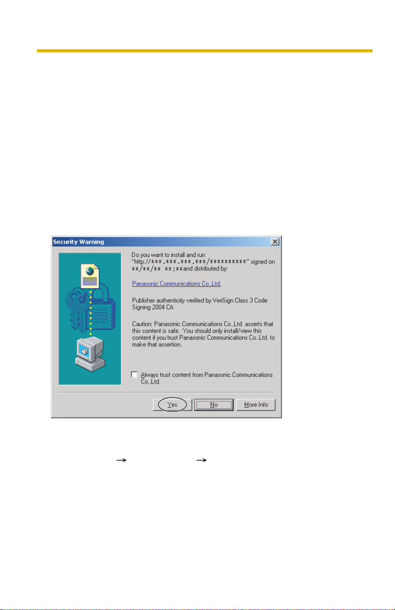
• When Security Warning window is displayed, click [Yes] (see page 18).
• See page 19 for Security Warning window when using Microsoft Windows
XP Service Pack 2.
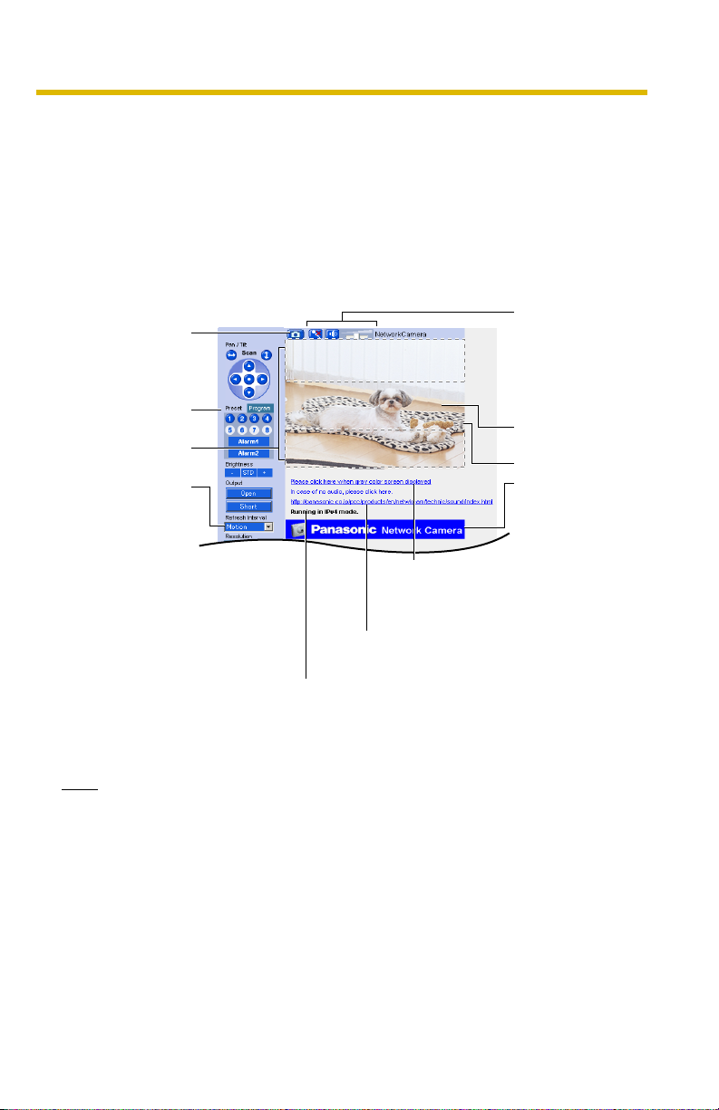
Capture Image
Button
(See page
Operation Bar
(See page 23)
Digital Zoom
(See page 25)
(See page
22)
Refresh
Interval
23)
Click the URL
when gray color
screen displayed.
Click the URL in case
of no audio.
Displaying to operate
with IPv4, IPv6, or IPsec.
Operating Instructions
Audio Control
Bar (Talk Button,
Listen Button
and Adjustment
Bar)
(See page 30)
Click to Center
(See page 21)
Camera Image
The banner is
displayed.
(See page 20)
3. Close the web browser.
Note
• Refresh interval is [Motion] by default. You can change it on the operation
bar (see page 23).
• Refresh interval may change depending on the network condition, PC
performance and what object you view. Using IPsec or enabling Motion
Detection will also slow refresh interval.
• When displaying video (Motion JPEG), the camera allows up to 30
simultaneous accesses. When trying more than 30 accesses, the 31st
user will see a gray screen. (Maximum 30 accesses for a Buffered Image
page too.)
[For assistance, please call: 1-800-272-7033] 17
Operating Instructions
• When the pan/tilt reaches the end, a shadow may be displayed partially.
This is not a problem.
• To reduce the data traffic, the video can be automatically changed to
refreshing still images on the General User page (see page
• To display the Single Camera page directly, add it to the [Favorites] on the
web browser.
• When you view a dark image, enable the color night view mode on the
Camera Setup page (see page 73). The image will be brighter, but the
refresh interval may slow down and image quality may decrease in a dark
place.
84).
Security Warning window
To view a video (Motion JPEG) or to use audio feature, ActiveX® Controls must be
installed. When trying to display a video for the first time, Security Warning window
will be displayed. When using Windows XP or Windows 2000, log in as an
administrator to install it.
If you cannot install ActiveX Controls or you cannot see the video in the
Internet Explorer
• Click [Tools] [Internet Options] [Security] tab and click [Custom level] on
the web browser.
(1) Check "Prompt" in "Download signed ActiveX Controls".
(2) Check "Enable" in "Run ActiveX Controls and plug-ins".
• ActiveX Controls can be installed from the file on the Setup CD-ROM.
(1) Restart the PC.
(2) Confirm that Internet Explorer is closed.
(3) Double-click "ocx\ActiveXInst.exe" on the Setup CD-ROM.
18
Operating Instructions
Note
• When the IP address was changed for the camera, enter it on the address bar.
• Video may not be displayed quickly or audio may not be listened immediately.
Wait for a while.
• If you use a proxy server, set the web browser not to access the proxy server
(see page 164).
• In some corporate network environments a firewall may be used for security
purposes. It is possible that this may prevent motion video from being
displayed. In this situation we suggest:
– Contact your network administrator.
– Try using regularly refreshed images.
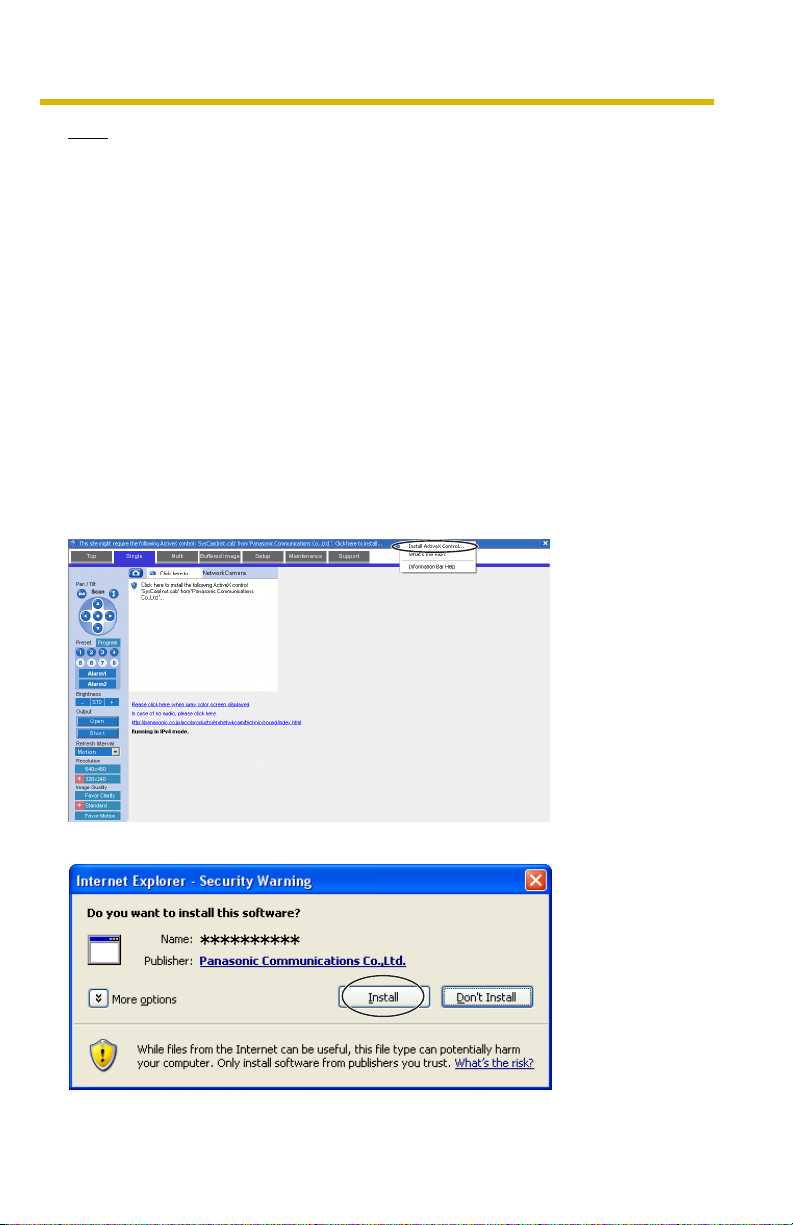
Security Warning window on Microsoft Windows XP Service Pack 2
To view a video (Motion JPEG) or to use audio feature, ActiveX Controls must be
installed.
Follow the steps shown below to install ActiveX Controls.
1. Click the warning displayed above the tabs, and click [Install ActiveX
Control...].
2. Click [Install].
[For assistance, please call: 1-800-272-7033] 19

Operating Instructions
The Banner
When the camera accesses the Internet, the banner displays product information
about cameras or announcements about the latest firmware, etc. from Panasonic.
Whether or not to display the banner can be set at Banner Display (see page
Note
• The banner is displayed when [Yes] is checked for Allow Access from the
Internet on the Automatic Setup page, or when [Enable] is checked for Auto
Port Forwarding on the UPnP page for the Connection Mode of Static or
DHCP.
• Even if [Yes] is checked for Allow Access from the Internet on the Automatic
Setup page, or [Enable] is checked for Auto Port Forwarding on the UPnP page
for the Connection Mode of Static or DHCP, when the camera is not connected
to the Internet,
is displayed.
125).
20
Operating Instructions
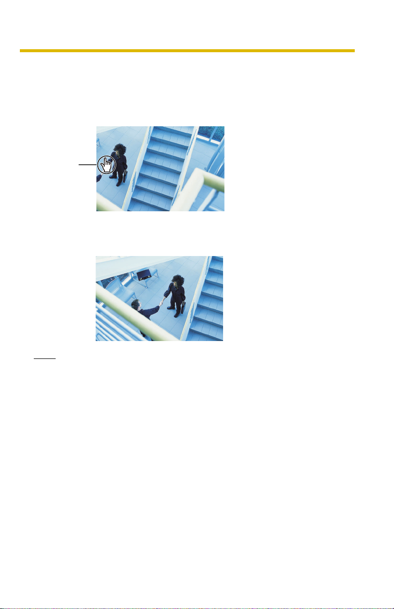
1.2.1 Auto Centering the Image (Click to Center)
Using your mouse, click any portion of the camera image. As long as it is within the
pan/tilt range of the camera, the image will automatically move to place the
selected point in the center of the screen.
1. Move the cursor to the desired point.
Cursor
2. Click it.
• The clicked point is centered.
• See page 24 for the pan/tilt operation.
Note
• When using the digital zoom feature, the Click to Center feature is
available.
• When End Display appears on the operation bar, Click to Center does not
work beyond the pan/tilt end (see page
• The clicked position may slightly miss the center depending on the lens
direction.
• If Click to Center is not permitted on the General User page (see page 84),
Click to Center does not work.
[For assistance, please call: 1-800-272-7033] 21
23).
Operating Instructions
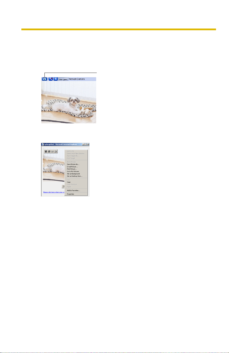
1.2.2 Capturing a Still Image
A still image can be saved on your PC.
1. Operate pan/tilt and select a resolution to display an image.
2. Click the capture image button.
Capture Image Button
• The camera image opens in another window.
3. Right-click the image, and select [Save Picture As...].
22
• Save as dialog box is displayed.
4. Specify a folder, and click [Save].
• Camera image is saved in the folder.
5. Click [Close].
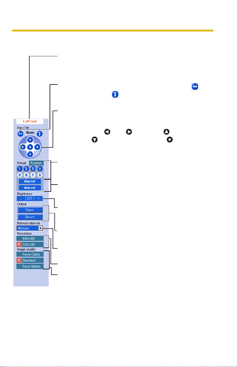
1.2.3 Using Operation Bar
Operating Instructions
End Display
and Preset
Display:
Pan/Tilt
Scan:
Pan/Tilt/
Home
Position:
Preset
Button:
Alarm
Position:
Brightness: Changes brightness in nine steps including [STD]
When the pan/tilt has reached the end (Left End,
Right End, Up End and Down End), End Display
appears. When clicking a preset button, the preset
name appears.
Moves the lens throughout the horizontal ( ) or
vertical ( ) range, and returns to the original
position.
Controls lens direction. The camera can be set up
to turn to the home position when detecting
motions.
Pan ( : Left, : Right), Tilt ( : Up,
[Default])
Applies the camera direction to a preset position.
The camera can be set up to turn to the preset
positions when detecting motions. You can preset 8
positions (see page
When the external sensor detects a signal, the
camera can be set up to turn to this position. Only
an administrator can operate it (see page
(Standard). Clicking [-] or [+] changes the image
brightness.
: Down) and Home Position ( : Center
26—page 29).
26).
Output
Control:
Refresh
Interval:
Resolution: Selects [640 x 480] or [320 x 240] (default) pixels.
Image
Quality:
[For assistance, please call: 1-800-272-7033] 23
Controls output signals of the External I/O.
Sets a refresh interval. (Motion—60-second
interval)
Selects the image quality.
• [Favor Clarity] optimizes the image for good
clarity.
• [Standard] keeps the standard quality. (default)
• [Favor Motion] optimizes the image for motion
display.
Operating Instructions
Note
When the camera image is not displayed correctly, click [Refresh] at the tool
bar on the web browser. The image will be refreshed.
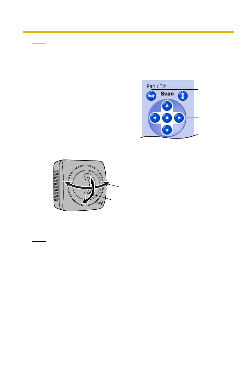
Pan/Tilt Operation
Pan/tilt scan buttons automatically move the
lens horizontally from -60 ° to +60 ° and
vertically from -45 ° to +20 ° and return the
lens to the original position. Each pan/tilt
arrow moves the lens Up, Down, Right or Left,
and the home position button moves it to the
home position.
Pan/Tilt Range
Pan/Tilt
Scan
Pan/Tilt
24
Pan: -60
Tilt: -45
˚ to +60 ˚
˚ to +20 ˚
Note
When the pan/tilt reaches the end, a shadow may be displayed partially. This
is not a problem.
Operating Instructions
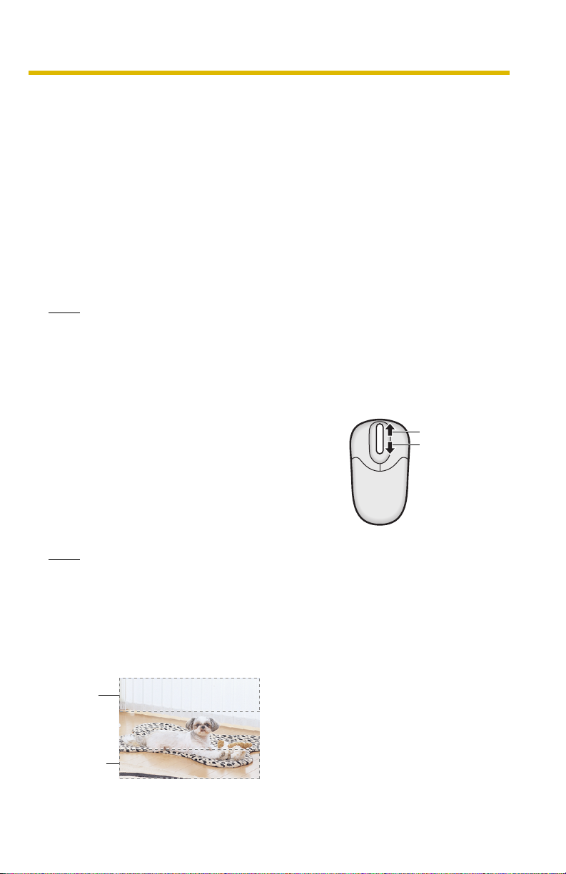
1.2.4 Zooming In and Out
Camera has a 10x digital zoom feature.
There are two methods of increasing/decreasing the size of the object on the
Single Camera screen, the Multi Camera screen, and the Buffered Image screen
(only while playing video):
1. Rotating the mouse wheel
Rotating the mouse wheel away from you zooms in, and rotating it towards
you zooms out.
2. Clicking the right mouse button
Clicking the right mouse button on the upper third of the Single Camera
screen zooms in, and clicking on the lower third of the Single Camera
screen zooms out.
Note
• The Click to Center feature is available even while zooming in or out.
• This feature is not available when viewing on a cell phone.
• As the magnification increases, the image quality decreases.
Rotating the mouse wheel
On a screen, rotating the mouse wheel away from
you zooms in, and rotating it towards you zooms
out.
Zoom in
Zoom out
Note
The performance of the mouse varies according to your OS.
Clicking the right mouse button
Clicking the right mouse button on the upper third zooms in, and clicking on the
lower third zooms out. Zooming in and out is also available by moving the mouse
up with pressing the right mouse button, or moving the mouse down with pressing
the right mouse button.
Zoom in
Zoom out
[For assistance, please call: 1-800-272-7033] 25
Operating Instructions
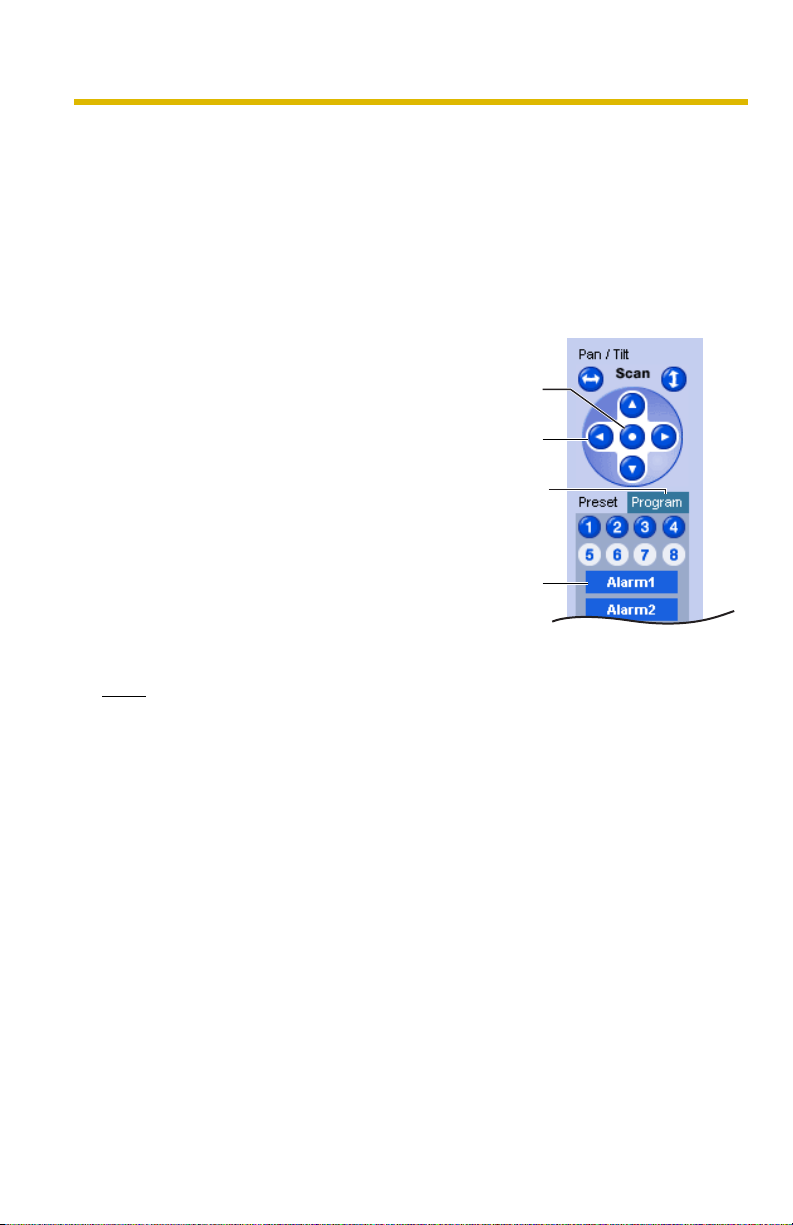
1.2.5 Setting Home Position/Alarm Position/Preset Button
Registering Home Position/Alarm Position
A home position or 2 alarm positions can be registered. When restarted, the
camera takes a home position. The alarm position is one that the camera turn to
when detecting alarms or motions. If the Lens Position When Triggered setting is
set (see page
External I/O detects a signal or the camera detects motions. See page 145 for the
External I/O.
1. Click [Program].
• [Program] switches to [Cancel].
2. Pan and tilt the camera to a desired
position.
3. Click the home position button or the
alarm position button.
4. Click [Save] to register, or click [Back]
and [Cancel] to cancel.
• If "Success!" is displayed, click
98 or page 108), the camera takes an alarm position after the
Click [Cancel] to quit without saving
changes.
Home
Position
Pan/Tilt
Program
Alarm
[Back].
Position
26
Note
The digital zoom value will not be saved.
Operating Instructions
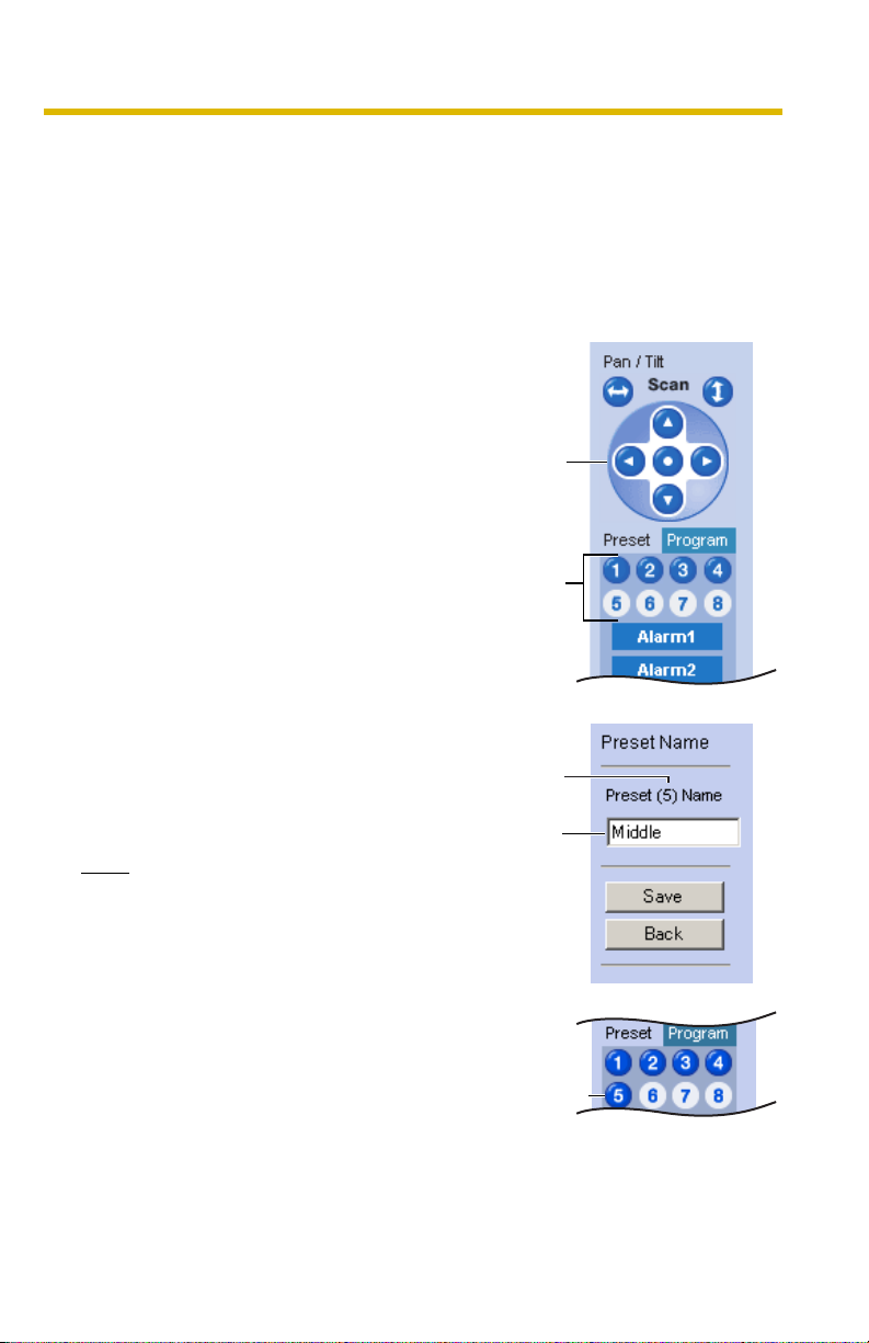
Registering a Preset Button
8 camera positions can be registered as presets. By default, the preset buttons
(1—4) are registered 1: Upper Left, 2: Upper Right, 3: Lower Left and 4: Lower
Right. These buttons can be changed (see page
turn to the preset positions when detecting motions.
• Registered buttons are shown in blue.
• Unregistered buttons are shown in white.
29). The camera can be set up to
1. Click [Program].
• [Program] switches to [Cancel].
Click [Cancel] to quit without saving
changes.
2. Pan and tilt the camera to a desired
position.
Pan/Tilt
3. Click a preset button (1—8) to register.
E.g.:
Setting "Middle" for the preset 5.
4. Enter the preset name.
• Maximum 15 characters.
• Enter ASCII characters (see page
168) or characters in each
language. But [Space], ["], ['], [&], [<]
and [>] are not available.
5. Click [Save] to register, or click [Back]
and [Cancel] to cancel.
• If "Success!" is displayed, click
[Back].
Note
• When registering preset buttons,
the camera also saves brightness
and white balance settings.
• Only an administrator can register
preset buttons.
• The digital zoom value will not be
saved.
Preset
Preset
number
Setting
a name
The button
turns blue.
[For assistance, please call: 1-800-272-7033] 27
Operating Instructions
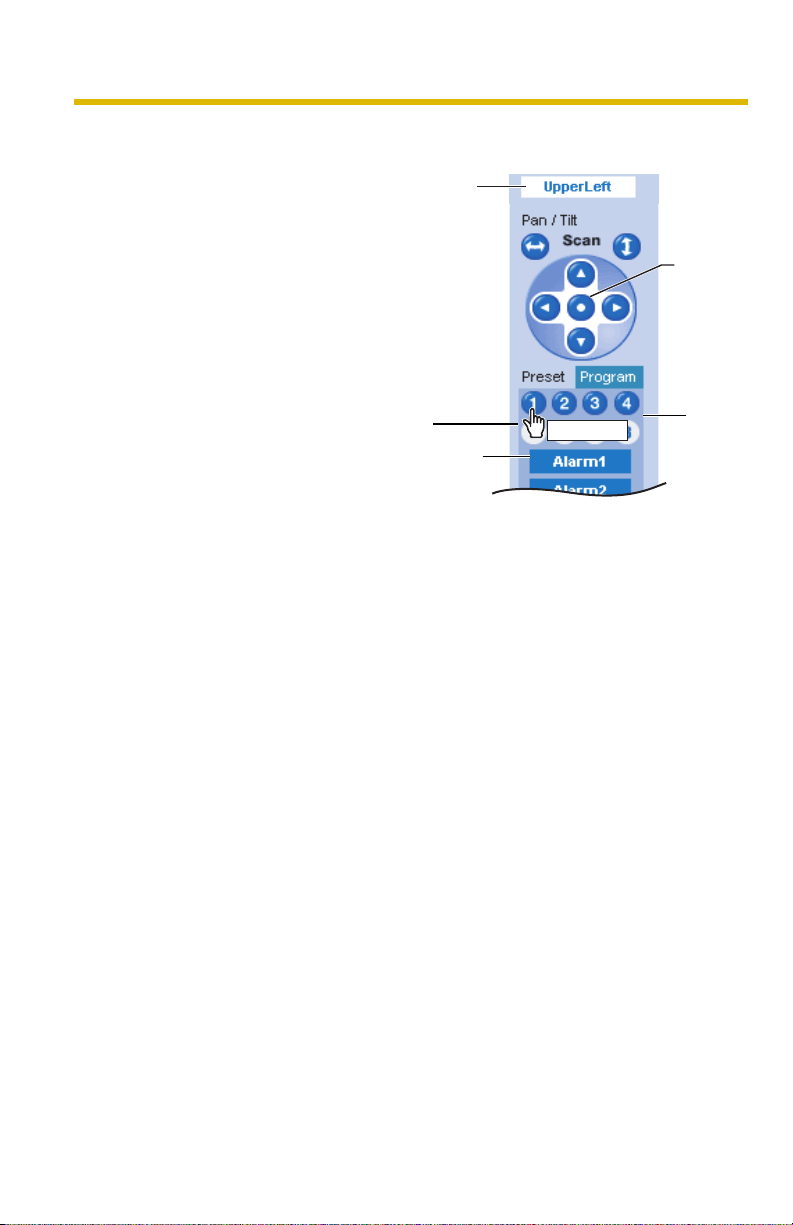
Viewing the Image
1. Click the home position,
alarm position or registered
preset button.
• The camera takes
each position, and the
image is displayed.
The preset
name will be
displayed
when the lens
reaches an
end.
Putting the
cursor displays
the preset
name.
Alarm
Position
UpperLeft
Home
Position
Preset
28
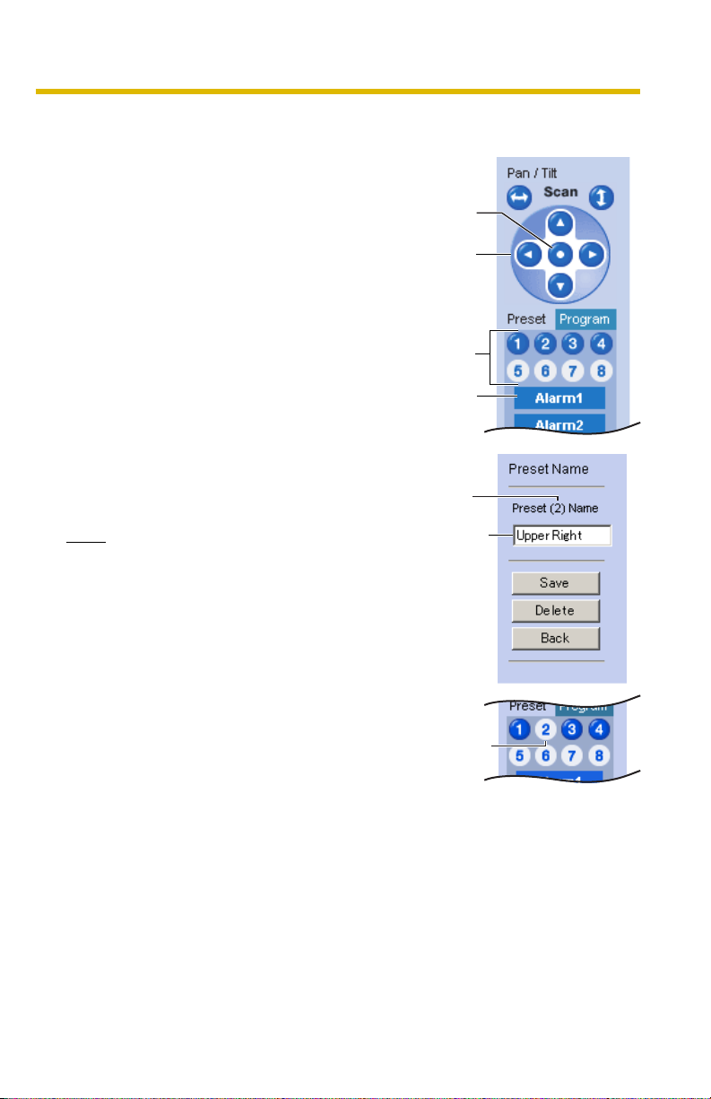
Changing or Deleting the Settings
1. Click [Program].
• [Program] switches to [Cancel].
Click [Cancel] to quit without saving
changes.
2. Pan and tilt the camera to a desired
position.
• When deleting, this step is not
necessary.
3. Click the home position, alarm position
or a preset button (1—8).
4. Click [Save] after setting the preset
name or click [Delete].
• If you quit to change or delete
settings, click [Back], and then
[Cancel].
• If "Success!" is displayed, click
[Back].
Operating Instructions
Home
Position
Pan/Tilt
Preset
Alarm
Position
Preset
number
Note
The home position or the alarm position
cannot be deleted, and these position
names cannot be changed either.
[For assistance, please call: 1-800-272-7033] 29
Changing
the name
The deleted
button turns
white.
Operating Instructions
1.3 Listening to Camera Audio—Talking to the
Camera
1. Access the camera (see page 13).
• The Top page is displayed.
2. Click the [Single] tab at the top of the page.
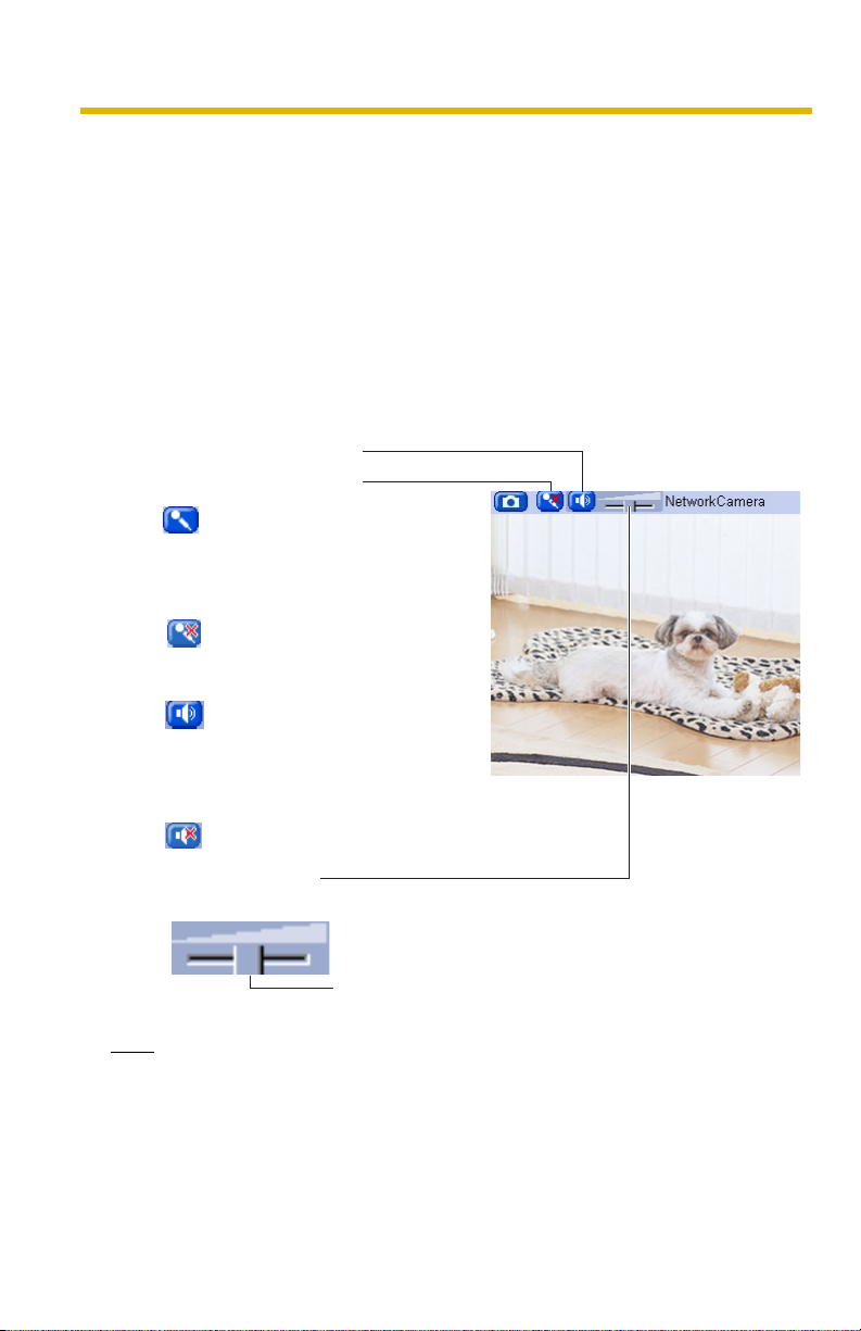
3. The Audio Control Bar (Talk Button, Listen Button and Adjustment Bar) is
displayed at the top of the screen. Listening or Talking is selected using the 2
icons. For general users, the feature must be enabled, otherwise it will not be
displayed.
Audio Feature
Listen Button
Talk Button
: You can talk from the
camera using the PC's
microphone. Clicking the
button temporarily stops
sending audio.
: The audio is stopped.
Clicking the button again
starts the Talk feature.
: You can listen to the audio
around the camera.
Clicking the button
temporarily stops the
audio.
: The audio is stopped.
30
Adjustment Bar
(Volume adjustment only for listening)
This slider adjusts the volume. To the right side, the
volume is larger. To the left side, the volume is smaller.
Note
• Talk button and Listen button cannot be used simultaneously. Talk feature is
stopped during listening. Talk feature can be used only for a user. Listen
feature can be used for maximum 10 users. If the audio is interrupted, reduce
the max. bandwidth (see page
users for listening are reduced.
43 and page 48). In this case, the number of
 Loading...