

PANASONIC KX-HCM10 User Manual

Network Camera
Operating Instructions
Model No.
KX-HCM10
Please read this manual before using and save this manual for future reference.
Panasonic Network Camera Site: http://www.panasonic.com/netcam
for customers in the USA or Puerto Rico

Introduction
Thank you for purchasing the Panasonic Network Camera.
Please check the following items when unpacking.
Operating Instructions
Setup CD-ROM
Operating Instructions
Getting Started
Camera Stand
AC adapter
Screws and Washers
— 1 pc.
— 1 pc.
— 1 pc.
— 1 pc.
— 1 pc.
— 2 pcs.
Directory and file structure of the Setup CD-ROM
The directory of the Setup CD-ROM and the main files are located as follows.
®
Acrobat® Reader 4.05 or later enables you to see the Operating
Adobe
Instructions in the Setup CD-ROM. Adobe Acrobat Reader installer is in the Setup
CD-ROM. Please double-click "ar405eng.exe".
Directory tree in the Setup CD-ROM
Kxhcm10
README.TXT
Setup.exe
AutoRun.inf
Netcam
Config.exe
Acrobat4.0installer
ar405eng.exe
Manual
OprInstr.pdf
OCX
Reghcm10.exe
Readme file (Please read first.)
Setup program
Information file to start Setup.exe
Network Configuration Setup Program directory
Network Configuration Setup Program
Acrobat Reader 4.0 Installer directory
Acrobat Reader 4.0 Installer
Operating Instructions
"kxhcm10.ocx" Installer directory
"kxhcm10.ocx" Installer
• When referring to the file structure, please use Explorer.
2

Operating Instructions
Before using
Please read Important Safety Instruction on Page 104 before using.
Read and understand all instructions.
For operation assistance:
• Call 1-800-272-7033
• Refer to the Panasonic Network Camera Site
http://www.panasonic.com/netcam
Trademarks
• Netscape and Netscape Navigator are registered trademarks of Netscape
Communications Corporation in the United States and/or other countries.
• Adobe and Acrobat are either registered trademarks or trademarks of Adobe
Systems Incorporated in the United States and/or other countries.
• Ethernet is a registered trademark of Xerox Corporation in the United States
and/or other countries.
• Microsoft, Windows, Windows NT and ActiveX are either registered
trademarks or trademarks of Microsoft Corporation in the United States and/
or other countries.
• Pentium is either a registered trademark or a trademark of Intel Corporation or
its subsidiaries in the United States and other countries.
• Screen shots reprinted with permission from Microsoft Corporation.
All other trademarks identified herein are the property of their respective owners.
Attach your purchase receipt here.
For your future reference
Serial No. Date of purchase
(found on the rear side of the unit)
Name and address of dealer
3

Operating Instructions
Table of Contents
1 Product Introduction ..................................................... 6
1.1 Getting to know the Network Camera............................................... 7
1.1.1 Main features...............................................................................................7
1.1.2 System Requirements.................................................................................9
1.1.3 Authentication – System Security feature..................................................10
1.2 Included Accessories...................................................................... 11
1.3 Camera Feature Locations ............................................................. 12
1.3.1 Front View .................................................................................................12
1.3.2 Rear View..................................................................................................13
1.3.3 Bottom View ..............................................................................................13
1.4 Network Camera connection .......................................................... 14
1.4.1 Selecting the Network Configuration.........................................................14
1.4.2 Mounting the Network Camera..................................................................16
1.4.3 Connecting Network Camera cable...........................................................18
1.4.4 Connecting the Power Suplly ....................................................................19
1.5 Network Configuration .................................................................... 20
1.5.1 Simple Installation using with the Setup CD-ROM....................................21
1.5.2 Configuring the Proxy Server ....................................................................36
1.5.3 Preliminary Operation – Accessing the Top Page.....................................39
2 Network Camera Screen and Window ....................... 40
2.1 Network Camera flow chart ............................................................ 41
2.2 Single Camera/Multi-Camera selection .......................................... 43
2.2.1 Viewing the Top View Image screen..........................................................45
2.3 Setup window – General Overview................................................. 52
2.3.1 Setting up the Network Camera ................................................................56
3 Network Camera Features .......................................... 87
3.1 Interfacing to the I/O Connector...................................................... 88
3.2 Network Camera reset procedure – default settings ...................... 90
3.3 Default settings list.......................................................................... 91
4 Specification and Troubleshooting............................ 96
4.1 Specification ................................................................................... 97
4.2 Troubleshooting .............................................................................. 99
4

Operating Instructions
4.3 Maintenance ................................................................................. 103
4.4 Important Safety Instruction ......................................................... 104
4.5 FCC and Other Information .......................................................... 106
Index
5

Section 1
Product Introduction
Operating Instructions
6

Operating Instructions
1.1 Getting to know the Network Camera
1.1.1 Main features
Easy installation
Installation is simplified using the Network Camera integrated web server and the
web browser. No additional software is required.
High Speed Motion JPEG
Using the Network Camera integrated web server, Motion JPEG, up to 15 frames
per second, can be displayed. To conserve bandwidth, JPEG - Regularly Refresh
can be selected from the Top Page. Refreshing interval can be set on the Top View
Image window.
Remote Pan/Tilt Operation
Pan/Tilt operation can move the lens horizontally 120° and downside 45°. This
movable lens allows you to see the situation in the wide room where the object is.
It can adjust the angle easily from the web browser.
Multi-Camera Screen
Using Multi-Camera screen you can simultaneously view up to four cameras at
various location. Clicking on each Camera Name switches to the Single Camera
screen from the Multi-Camera screen.
Multi Client Access
The Network Camera allows the 10 users to view the Motion JPEG image
simultaneously. The users can access the Top View Image screen (Single
Camera/Multi-Camera screen) from their own locations.
I/O (Input/Output) Connector
I/O connector consists of the digital input/output terminal. The external
sensors/devices such as a door sensor can connect to the digital input terminal.
The external sensors/devices are customer provided. Any required custom
interface is the customer's responsibility. The alarm/timer trigger can activate the
Image Transfer feature which can send the images via e-mail or FTP (File Transfer
Protocol).
The digital output terminal can send a signal to activate the external devices such
as a light around the Network Camera.
7

Operating Instructions
Update Firmware
If Update Firmware is released, you can download the latest program from the
Network Camera Technical Support Site. Installation is easy and fast. Please refer
to Page 83 for details.
Authentication
Authentication window requires you to enter the administrator/general user ID
and password. Password security can prevent the unregistered user from
accessing your image from their web browsers. Please refer to Section
1.1.3 Authentication – System Security feature for details.
8

Operating Instructions
1.1.2 System Requirements
The PC (Personal Computer) and the network must meet the following technical
specifications for the Network Camera to work properly.
Item Description
Operating
System
Network
Protocol
Microsoft® Windows® 95, Microsoft Windows 98/SE
Microsoft Windows 2000, Microsoft Windows ME
Microsoft Windows NT
®
4.0, Microsoft Windows XP
TCP/IP network protocol installed.
(HTTP, FTP, SMTP, TCP, UDP, IP, ARP, ICMP)
• The Network Camera does not support PPPoE (Point-to-
®
Point Protocol over Ethernet
CPU Pentium
®
II 300 MHz or greater
).
Interface 10/100 Mbps Ethernet card and category 5 cables for your
network connection
1
Web browser*
Internet Explorer 5.0 or later/Netscape Navigator® 4.7
Please use Microsoft Internet Explorer version 5.0 or later.
(It is not included in the Setup CD-ROM).
1
The Network Camera image is not displayed correctly on the Netscape®
*
v6.x. Please use Netscape v4.7.
Please refer to Panasonic Network Camera Site
http://www.panasonic.com/netcam about the latest information of the web
browser.
9

Operating Instructions
1.1.3 Authentication – System Security feature
Authentication window requires you to enter the administrator/general user ID
and password. Password security can prevent the unregistered user from
accessing your image from their web browsers. Authentication windows are not
displayed in the default. "User Name" and "Password" are case sensitive. Please
refer to Page 60 for setting up Authentication window, administrator ID and
password. Please refer to and Page 62 for setting up the general user ID and
password.
Authentication window
Note
Please refer to Page 61 for the detail password security.
10

Operating Instructions
1.2 Included Accessories
The following items are provided with the Network Camera. Additional pieces can
be ordered by calling 1-800-332-5368.
AC adapter — 1 pc.
Order No. PQLV10Y
Screws — 2 pcs.
Order No. PQHE5004Z
Washers — 2 pcs.
Order No. XWG35FY
Notes
• If any items are missing, please contact the dealer immediately.
• The order numbers listed above are subject to change without notice.
• Save the original carton and packing materials for future shipping and
transportation of the unit.
• Do not scratch, smudge, write or label either surfaces of the Setup CD-
ROM. Setup CD-ROM may have a scratch on the surface.
• Do not leave the Setup CD-ROM in direct sunlight, near a heat source or
in a hot automobile. It may transform the surface of the Setup CD-ROM.
• Do not use chemicals or cleanser to clean the Setup CD-ROM. It may
transform the surface of the Setup CD-ROM.
Camera Stand — 1 pc.
Order No. PSKLHCM10M
Setup CD-ROM — 1 pc.
Order No. PSQX2432
11

1.3 Camera Feature Locations
1.3.1 Front View
Power LED
(Refer to Page 81 for the Setup.)
Fixed Focus Lens
40 inches (1 m) – Infinity
Pan: - 60° to + 60°
Tilt: 0° to - 45°
Power LED
During normal operation Power LED will be on in the default.
Blinking will occur during the following situation.
• During the lens center positioning after turning on the power.
• During the Update Firmware.
• During initializing after pushing CLEAR SETTING button.
• During getting the IP address from the DHCP server.
• During a camera malfunction. Please refer to Section
4.2 Troubleshooting.
Operating Instructions
Fixed Focus Lens and Pan/Tilt operation
Fixed Focus Lens can move in the Pan/Tilt operation. Operation Bar on the Single
Camera screen can operate the Pan/Tilt. The Pan/Tilt moves the lens horizontally
120° and downside 45°. Please refer to Page 47 for the Operation Bar.
Notes
• Do not force to move the lens part around the Fixed Focus Lens.
Compulsive touching may damage the Pan/Tilt motor.
• Do not touch the Fixed Focus Lens. It may leave a finger print and can
cause the image to be out of focus. This can also take away the
protective coating on the Fixed Focus Lens.
12

Operating Instructions
1.3.2 Rear View
I/O Connector
(Refer to
Page 88.)
Ethernet port
(RJ-45)
(Refer to
Page 18.)
DC IN jack
(Refer to
Page 19.)
Ethernet
Indicator
(Refer to
Page 18.)
Ethernet indicator
Ethernet indicator blinks when the network is active. It blinks when the network
tries to find the Network Camera. If it is off, please refer to Section
4.2 Troubleshooting.
1.3.3 Bottom View
CLEAR SETTING button
(Refer to Page 90.)
MAC address and serial
number are indicated on
the label.
(Refer to Page 23.)
Used for mounting the
unit on the Camera Stand
or the wall.
(Refer to Page 16.)
Hook for AC adapter cable
(Refer to Page 19.)
Tripod Mounting
Hole
(Refer to Page 16.)
13

Operating Instructions
1.4 Network Camera connection
Please review the five types of typical Network Configuration on Page 14 and
Page 15.
1.4.1 Selecting the Network Configuration
Direct Connection to PC (without Ethernet hub)—[Type 1]
AC adapter
Power
outlet
Without Ethernet hub, you should use category 5 cross cable.
LAN Connection with Ethernet Switching Hub—[Type 2]
14
AC adapter
Power
outlet
1
Network traffic can be smooth by using the Ethernet switching hub.
*
Ethernet
switching hub*
1
LAN
Category 5
straight cable
Ethernet
switching hub*
1

Operating Instructions
Internet Connection
The Network Camera can connect over the Internet. The Network Camera has the
HTTP server. Please confirm the ISP (Internet Service Provider) or administrator
permit you to use the HTTP server.
Internet Direct Connection with Cable modem—[Type 3]
Cable modem
(1 port)
Single
Network Camera
Internet
Cable line
• Network Camera does not support PPPoE. With PPPoE, please connect
with the router corresponding with PPPoE in Type 4 and 5.
Internet Connection with Cable/xDSL modem and Router—[Type 4]
Internet
Cable/xDSL
line
Cable/xDSL
modem
(1 port)
Router*
2
*2 The router can be Panasonic Broadband Networking Gateway
KX-HGW200. The router needs Port Forwarding feature on Page 33.
Internet Connection with Cable/xDSL modem with the router feature
—[Type 5]
Internet
Cable/xDSL modem with
the router feature*
Cable/xDSL
line
3
*3 The router needs Port Forwarding feature on Page 33.
15

Operating Instructions
1.4.2 Mounting the Network Camera
Four mounting methods are shown in the following figures. Please confirm the top
and bottom of the Network Camera when mounting.
Camera Stand Mounting
Fix the Network Camera to the Camera
Stand.
top
bottom
Wall Mounting
Screw the two screws
a)
(accessories) into the wall. The
distance of two screws should
be 2.75" (70 mm).
Fix Network Camera to the
b)
screws.
top
a)
Tripod Mounting
Attach the Network Camera to the
tripod by using the tripod bolt.
Ceiling Mounting
Screw the two screws
a)
(accessories) into the ceiling.
The distance of two screws
should be 2.99" (76 mm).
Fix Network Camera to the
b)
Camera Stand.
Fix Camera Stand to the screws.
c)
2.99" (76 mm)
a)
b)
2.75" (70 mm)
bottom
b), c): Fix the unit tightly by sliding it.
16
c)
top
b)
bottom

Operating Instructions
Note
Make sure the Power LED is always in the upper right corner when you mount.
The upside down mounting may cause the Network Camera to slip off the
Camera Stand and fall down.
Power LED
top
bottom
top
bottom
Ceiling Mounting Wall MountingCamera Stand Mounting
CAUTION
Network Camera is intended for indoor use only. Prolonged exposure to direct
sunlight or halogen light may damage the CMOS sensor.
17
Operating Instructions
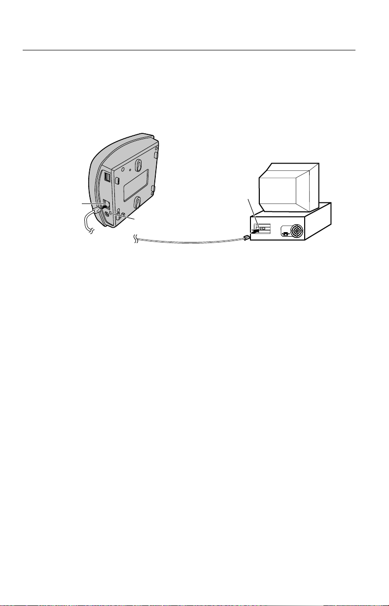
1.4.3 Connecting Network Camera cable
Connection of the Network Camera to the PC or network device is made with
category 5 cable. If the Network Camera is connected directly to the PC, a
category 5 cross cable must be used. Ethernet indicator blinks when the network
is active. Please refer to Page 14 and Page 15.
Ethernet
port
To Network
Ethernet port
Ethernet inidicator
PC (Rear Side)
18

Operating Instructions
1.4.4 Connecting the Power Suplly
Connect the DC plug of the AC adapter to the DC IN jack of the Network
1.
Camera and connect the AC plug of the AC adapter to the power outlet to turn
on the Network Camera.
Power Outlet
(120 V AC, 60 Hz)
AC plug
AC adapter
(included
accessory)
DC plug
* Thread the AC adapter line
through the hook downward.
* Thread the AC adapter
line through the hook
upward if it is convenient.
Notes
• Plugging in/off the AC adapter means turning on/off the Network
Camera. The AC adapter should be located near the unit and be easily
accessible.
• Use Only with Panasonic AC adapter (Order No. PQLV10Y).
After the AC adapter is connected to the outlet, the Power LED turns on and
2.
the Pan/Tilt moves to the center position.
19

Operating Instructions
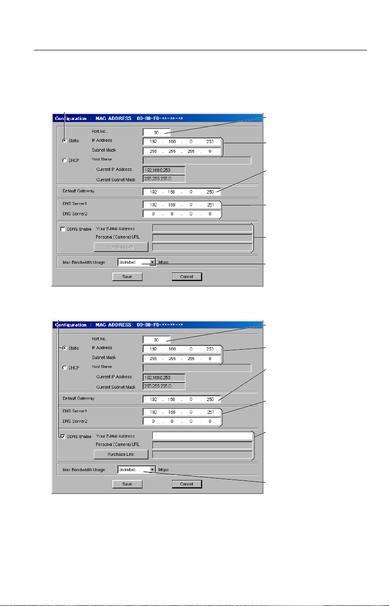
1.5 Network Configuration
The Network Camera parameters are set by the Configuration window. The
main parameters are listed below. When the Network Camera is installed on a
large network, please consult the ISP or the network administrator before
proceeding so that the Network Camera does not conflict with other network
devices.
• Static: IP address/Subnet Mask of the Network Camera
or the Host Name in case of the DHCP (Dynamic Host Configuration
Protocol)
• Port no. (In case you can not use port no. 80 depending on the ISP, please
get the available port no. (Default 80) in the global IP address from the ISP
or network administrator.)
• Default Gateway
• DNS Server 1/DNS Server 2 (DNS: Domain Name System)
• DDNS (Dynamic Domain Name System): Your e-mail address/Personal
(Camera) URL/Purchase Link
• Max Bandwidth Usage
20

Operating Instructions
1.5.1 Simple Installation using with the Setup CD-ROM
The Setup CD-ROM simplifies the installation. Insert the Setup CD-ROM and
autorun should start the application automatically. This program will automatically
locate the Network Camera on the network without installing any software. Once
you become more familiar with the Network Camera, Setup Page configures all
of its settings. The detail explanation of the parameters on the Configuration
window is on Page 27 to Page 32. All connections including Internet connections
need the following procedures to set up the Network Camera at the beginning.
To set up the Network Camera, connect locally between the PC and the
1.
Network Camera.
(Without Ethernet hub, you should use category 5 cross cable.)
or
Ethernet hub
(Category 5 straight cable)
or
Router
Note
When setting up from the PC on the different network over the router, the
Setup program can not detect the Network Camera.
21

Operating Instructions
Insert the Setup CD-ROM in the CD-ROM drive of the PC.
2.
(If the Network Camera Setup window does not appear, please click
"setup.exe" in the Setup CD-ROM.)
22

Operating Instructions
Click [Network Camera Configuration]. The Network Camera List window
3.
appears. The Setup program finds all the Network Cameras connected in the
LAN. The Network Camera List window lists all of the MAC addresses and
IP addresses of the Network Camera on the network.
Note
The software on the Setup CD-ROM assists you with the installation of the
Network Camera. It locates and identifies the Network Camera by listening
for data which the Network Camera sends out for the first 20 minutes after
the Network Camera is powered up. If the installation is not completed
within 20 minutes, please temporarily disconnect the power to restart this
operation.
(i)
23

Operating Instructions
MAC address
Ethernet defines a 48-bit addressing scheme. Ethernet hardware
manufacturers purchase blocks of Ethernet addresses and assign them in
sequence to their Ethernet interface hardware. No two hardware interfaces
have the same Ethernet address. Ethernet address are sometimes called
hardware addresses, physical addresses, media access (MAC)
addresses, or layer 2 addresses. MAC address is used in this manual.
Notes
• Each Network Camera has a unique MAC address labeled on the back
as 00-80-f0-XX-XX-XX. ("X" is the number or alphabet of 0 – f.)
• The MAC address tells you which Network Camera you would like to
set up by confirming the rear side of the target Network Camera in case
there are many Network Cameras on the LAN.
• IP addresses of all Network Cameras connected to the LAN are
displayed.
• If the error message appears in Network Camera getting the IP
address, please do the following steps.
Error message
24
1. Disconnect the AC adapter of the Network Camera.
2. Please confirm if the cables on the network are connected properly.
3. Reconnect the AC adapter and run the Setup program again.
4. During this process the Ethernet indicator near the Ethernet port of the
Network Camera should be flashing.

Operating Instructions
Select your target Network Camera from the list as shown on example (i) on
4.
the Network Camera List window on Page 23 and click [Select]. The
Configuration window appears. Please refer to Page 27 – Page 32 for the
detail parameters.
Click [Save] when finishing. The "Successful!" message box appears.
5.
25

Operating Instructions
Notes
• The Network Camera automatically restarts after saving the network
configuration.
• Power LED blinks during getting the IP address from the DHCP server.
• Overlapped IP address displays the next box.
Confirm the IP address and try to set up again. If you can not set up,
please ask the ISP or the network administrator.
Click [OK].
6.
26
To the Top Page, Click [OK].
To confirm the parameters after this operation.
Please refer to Section 1.5.3 Preliminary Operation – Accessing the Top
Page.
Notes
• The proxy server may prevent you from connecting directly to the
Network Camera. Please refer to Section 1.5.2 Configuring the Proxy
Server.
• To access the Top Page in the LAN, the Network Camera needs the
private IP address in the same class of the PC. Please refer to Page 33.

Operating Instructions
Setting Network Parameters
Confirm which type of the Network Configuration you are using as shown in
Section 1.4.1 Selecting the Network Configuration on Page 14 and Page 15.
Please refer to Page 31 for the detail of each parameter.
Direct Connection to PC (without Ethernet hub)—[Type 1]
Check
Set to 80. [Default]
Static IP address
and Subnet Mask.
You do not need to
set up.
from 0.1 to
Unlimited Mbit/s.
LAN Connection with Ethernet Switching Hub—[Type 2]
Check
Set to 80. [Default]
Static IP address
and Subnet Mask.
Default Gateway
address. Please
ask administrator.
DNS server address.
Please ask administrator.
You do not need to
set up.
From 0.1 to
Unlimited Mbit/s.
27

Internet Direct Connection with Cable modem—[Type 3]
Please confirm whether or not the ISP supports DHCP.
• When the ISP does not support DHCP
Check
Set to 80. [Default]
Static IP address
and Subnet Mask.
Default Gateway
address. Please
ask ISP or administrator.
DNS server address.
Please ask ISP or
administrator.
You do not need to
set up.
From 0.1 to
Unlimited Mbit/s.
• When the ISP supports DHCP
Check
Operating Instructions
Set to 80. [Default]
Host Name of the
Network Camera if ISP
needs you to set.
Default Gateway
address. Please ask ISP
or administrator.*
DNS server address.
Please ask ISP or
administrator.*
Contract to DDNS
service. Please refer to
an attached leaflet.
From 0.1 to
Unlimited Mbit/s.
a
*
If you automatically get the address from DHCP server, you do not need to
set up.
28
a
a
Operating Instructions
Internet Connection with Cable/xDSL modem with the router feature
—[Type 4, 5]
• When the ISP does not support DHCP
Check
Port no. for each
Network Cameras*
Static IP address and
Subnet Mask*
IP address of your router
(in the LAN), not of the
gateway of ISP*
DNS server address.
Please ask ISP or
administrator.
You do not need to
set up.
From 0.1 to
Unlimited Mbit/s.
• When the ISP supports DHCP
Check
Port no. for each
Network Cameras*
Static IP address and
Subnet Mask*
IP address of your router
(in the LAN), not of the
gateway of ISP*
DNS server address.
Please ask ISP or
administrator.
Contract to DDNS
(Dynamic Domain Name
System) service. Refer to
an attached leaflet for
DDNS service.
From 0.1 to
Unlimited Mbit/s.
*b Set Port Forwarding feature to the router. Please refer to Page 33.
c
*
Please refer to the router's manual for details.
b
c
c
b
c
c
29

Network Configuration table
Operating Instructions
Configuration
window
Por t No.
IP address
and Subnet
Mask
Check the Static, and set
Static IP address and
Subnet Mask.
1
Network Configuration Type
2
3
Set to 80. [default]
Check Static or
DHCP, which the
ISP provides.
Enter IP address
Check the Static,
and set Static IP
address and
Subnet Mask. *
and Subnet Mask
(Static) or the Host
Name (DHCP).
Default
Gateway
You do not
need to
set up.
If you use
Gateway,
you need
to set it.
If you use Gateway,
you need to set
2
it. *
You need to set IP
address of your
router (in the
LAN), not of the
gateway of the
4
ISP. *
DNS
Server 1, 2
You do not
need to
set up.
If you use
DNS, you
need to
If you use DNS, you
need to set
2
it. *
If you use DNS,
you need to set
it.
set it.
DDNS
Max.
Bandwidth
Usage
*1 :
2
*
:
3
*
:
4
:
*
5
:
*
You do not need to setup.
It can restrict the transmit bandwidth.
Select from 0.1 to Unlimited Mbit/s.
The Network Cameras need its own port no. for each Network Camera. The router
needs the Port Forwarding feature.
If you automatically get the address of Default Gateway and DNS server from
DHCP server, you do not need to set up.
Please confirm whether or not the ISP supports DHCP. If the ISP supports DHCP,
you need to contract and register DDNS service. Please refer to an attached leaflet
for DDNS service. If you set global Static IP Address, you do not need to set DDNS
item.
Please refer to the router's manual for the detail.
Please confirm whether or not the ISP supports DHCP. If the ISP supports DHCP,
you need to contract and register DDNS service. Please refer to an attached leaflet
for DDNS service.
3
*
4, 5
*
5
*
1
4
30
 Loading...