

Page 1

CTi Automation - Phone: 800.894.0412 - Fax: 208.368.0415 - Web: www.ctiautomation.net - Email: info@ctiautomation.net
TEMPERATURE CONTROLLER
KT9
INSTRUCTION MANUAL
Page 2

PPrreeffaaccee
CTi Automation - Phone: 800.894.0412 - Fax: 208.368.0415 - Web: www.ctiautomation.net - Email: info@ctiautomation.net
Thank you for the purchase of Temperature controller KT9.
This manual contains instructions for the mounting, functions, operations and notes when
operating the KT9.
For model confirmation and unit specifications, please read this manual carefully before
starting operation.
To prevent accidents arising from the misuse of this controller, please ensure the
operator receives this manual.
Notes
• This instrument should be used according to the specifications described in t he manual.
If it is not used according to the specifications, it may malfunction or cause fire.
• Be sure to follow the warnings, cautions and notices. If they are not observed, it could cause
serious injury or accidents.
• The contents of this instruction manual are subject to change without notice.
• Care has been taken to assure that the contents of this instruction manual are correct, but if
there are any doubts, mistakes or questions, please inform our sales department.
• This instrument is designed to be installed in a control panel. If it is not, measures must be
taken to ensure that the operator cannot touch power terminals or other high voltage
sections.
• Any unauthorized transfer or copying of this document, in part or in whole, is prohibited.
• Matsushita Electric Works, Ltd. is not responsible for any damage or secondary damage(s)
incurred as a result of using this product, including any indirect damage.
• To pull out the inner assembly, release the hooks at the top and bottom of the instrument
with thin, hard tweezers. (If the hooks are released too far, they may be broken, or IP66
function could deteriorate. Do not pull out the inner assembly except when repairing the
instrument.)
SAFETY PRECAUTIONS
(
Be sure to read these precautions before using our products.
The safety precautions are classified into categories: “Warning” and “Caution”.
Depending on circumstances, procedures indicated by
results, so be sure to follow the directions for usage.
Warning
Procedures which may lead to dangerous conditions and cause death or serious
injury, if not carried out properly.
Caution
Procedures which may lead to dangerous conditions and cause superficial to medium
injury or physical damage or may degrade or damage the product, if not carried out
properly.
2
Caution may be linked to serious
)
Page 3
11.. IInnssttaallllaattiioonn pprreeccaauuttiioonns
CTi Automation - Phone: 800.894.0412 - Fax: 208.368.0415 - Web: www.ctiautomation.net - Email: info@ctiautomation.net
Caution
This instrument is intended to be used under the following environmental conditions
(IEC61010-1): Overvoltage category
Ensure the mounting location corresponds to the following conditions:
• A minimum of dust, and an absence of corrosive gases
• No flammable, explosive gases
• No mechanical vibrations or shocks
• No exposure to direct sunlight, an ambient temperature of 0 to 50
that does not change rapidly
• An ambient non-condensing humidity of 35 to 85%RH
• No large capacity electromagnetic switches or cables through which large current
is flowing
• No water, oil or chemicals or where the vapors of these substances can come into
direct contact with the unit
Note: Do not install this instrument near flammable material even though the case of
this instrument is made of flame-resistant resin.
Avoid setting this instrument directly on flammable material.
s
, Pollution degree 2
(32 to 122 )
22.. WWiirriinngg pprreeccaauuttiioonns
Caution
• Use the solderless terminal with an insulation sleeve that fits in the M3 screw when
wiring the KT9 Series.
• The terminal block of this instrument is designed to be wired from the left side.
The lead wire must be inserted from the left side of the terminal, and fastened with
the terminal screw.
• Tighten the terminal screw within the specified torque.
If excessive force is applied to the screw when tightening, the terminal screw or
case may be damaged.
• Do not apply a commercial power source to the sensor which is connected to the
input terminal nor allow the power source to come into contact with the sensor.
• This controller does not have built-in power switch, circuit breaker or fuse.
It is necessary to install them near the controller.
(Recommended fuse: Time-lag fuse, rated voltage 250V AC, rated current 2A)
• For a 24V AC/DC po wer source, do not confuse polarity when using direct current (DC).
33.. RRuunnnniinngg aanndd mmaaiinntteennaannccee pprreeccaauuttiioonnss
Warning
• It is recommended that the PID auto-tuning be performed on the trial run.
• Do not touch live terminals. This may cause electric shock or problems in operation.
• Turn the power supply to the instrument OFF before retightening the terminal
and cleaning.
Working or touching the terminal with the power switched ON may result in severe
injury or death due to Electric Shock.
• Use a soft, dry cloth when cleaning the instrument.
(Alcohol based substances may tarnish or deface the unit)
• As the display section is vulnerable, do not strike or scratch it with a hard object.
s
3
Page 4

CTi Automation - Phone: 800.894.0412 - Fax: 208.368.0415 - Web: www.ctiautomation.net - Email: info@ctiautomation.net
---
CONTENTS
---
1. Model number
1.1 Explanation of model number ----------------------- ----------------------------- 6
1.2 Rated input ---------------------------------------------------------------------------- 7
1.3 How to read the rated label ------------------------------------------------------- 7
2. Name and functions of the sections
------------------------------------ 8
3. Mounting to the control panel
3.1 Site selection ----------------------------------------------------------------------- 10
3.2 External dimensions (Unit: mm) ----------------------------------------------- 10
3.3 Panel cutout (Unit: mm) ---------------------------------------------------------- 10
3.4 CT (current transformer) external dimensions (Unit: mm) --------------- 11
3.5 Mounting -------------------------------- ---------------------------------------- ----- 11
4. Wiring
4.1 Terminal arrangement ------------------------------------------------------------ 12
4.2 Wiring examples ------------------------------------------------------------------- 13
5. Setup
5.1 Operation flowchart --------------------------------------------------------------- 16
5.2 Main setting mode
SV1 ------------------------------------------------------------------------------------- 18
SV2 ------------------------------------------------------------------------------------- 18
5.3 Output MV indication --------------------------------------------------------------18
5.4 Sub setting mode
AT/Auto-reset ------------------------------------------------------------------------ 18
OUT1 proportional band ---------------------------------------------------------- 19
OUT2 proportional band ---------------------------------------------------------- 19
Integral time -------------------------------------------------------------------------- 19
Derivative time ---------------------------------------------------------------------- 19
ARW (Anti-reset windup) ------------------------------------------------- - ----- -- 19
OUT1 proportional cycle ---------------------------------------------------------- 19
OUT2 proportional cycle --------------------------------------------------------- 19
A1 value ------------------------------------------------------------------------------ 20
A2 value ------------------------------------------------------------------------------ 20
HB (Heater burnout alarm) value ---------------------------------------------- 20
5.5 Auxiliary function setting mode 1
Set value lock ----------------------------------------------------------------------- 21
SV high limit ------------------------------------------------------------------------- 21
SV low limit -------------------------------------------------------------------------- 21
Sensor correction ------------------------------------------------------------------ 21
Communication protocol --------------------------------------------------------- 21
Instrument number ---------------------------------------------------------------- 21
Communication speed ------------------------------------------------------------ 21
Parity ---------------------------------------------------------------------------------- 22
Stop bit -------------------------------------------------------------------------------- 22
5.6 Auxiliary function setting mode 2
Input type ----------------------------------------------------------------------- ------ 22
Scaling high limit ------------------------------------------------------------------- 23
Scaling low limit -------------------------------------------------------------------- 23
Decimal point place --------------------------------------------------------------- 23
PV filter time constant ------------------------------------------------------------ 23
4
Page 5

CONTENTS
CTi Automation - Phone: 800.894.0412 - Fax: 208.368.0415 - Web: www.ctiautomation.net - Email: info@ctiautomation.net
---
OUT1 high limit ---------------------------------------------------------------------- 23
OUT1 low limit ----------------------------------------------------------------------- 23
OUT1 ON/OFF action hysteresis ----------------------------------------------- 23
OUT2 action mode ----------------------------------------- - ----- ---- --- ---- - ------ 23
OUT2 high limit ---------------------------------------------------------------------- 24
OUT2 low limit ----------------------------------------------------------------------- 24
Overlap band/Dead band --------------------------------------------------------- 24
OUT2 ON/OFF action hysteresis ----------------------------------------------- 24
A1 type -------------------------------------------------------------------------------- 24
A2 type -------------------------------------------------------------------------------- 25
A1 action Energized/Deenergized --------------------------------------------- 25
A2 action Energized/Deenergized --------------------------------------------- 25
A1 hysteresis ------------------------------------------------------------------------ 25
A2 hysteresis ------------------------------------------------------------------------ 25
A1 action delayed timer ----------------------------------------------------------- 25
A2 action delayed timer ----------------------------------------------------------- 25
Direct/Reverse action ------------------------------------------------------------- 26
AT bias -------------------------------------------------------------------------------- 26
Setting item not used -------------------------------------------------------------- 26
SV2 indication ---------------------------------------------------------------------- 26
Output status selection when input abnormal ------------------------------- 26
OUT/OFF key function ------------------------------------------------------------ 26
5.7 Control output OFF function --------------------------------------------------- 27
5.8 Auto/Manual control -------------------------------------------------------------- 27
6. Running
----------------------------------------------------------------------------- 28
---
7. Action explanation
7.1 OUT1 action ------------------------------------------------------------------------ 29
7.2 Heater burnout alarm action (option) ----------------------------------------- 29
7.3 OUT1 ON/OFF action ------------------------------------------------------------ 30
7.4 OUT2 (Heating/Cooling control) action (option) --------------------------- 31
7.5 OUT2 (Heating/Cooling control) action (when setting Dead band) --- 32
7.6 OUT2 (Heating/Cooling control) action (when setting Overlap band)-33
7.7 A1, A2 action ------------------------------------------------------------------------ 34
7.8 SV1/SV2 external selection ----------------------------------------------------- 35
8. Control action explanations
8.1 PID ------------------------------------------------------------------------------------ 35
8.2 PID auto-tuning of this controller ---------------------------------------------- 35
8.3 Auto-reset (offset correction) --------------------------------------------------- 36
9. Specifications
9.1 Standard specifications ------------------------------------------------------ ---- 37
9.2 Optional specifications ----------------------------------------------------------- 42
10.Troubleshooting
10.1 Indication -------------------------------------------------------------------------- 44
10.2 Key operation -------------------------------------------------------------------- 45
10.3 Control ----------------------------------------------------------------------------- 46
11. Character table
----------------------------------------------------------------- 46
5
Page 6

1. Model number
CTi Automation - Phone: 800.894.0412 - Fax: 208.368.0415 - Web: www.ctiautomation.net - Email: info@ctiautomation.net
1.1 Explanation of model number
A K T 9
(1) (2) (3) (4) (5) (6) (7)
(1) Supply voltage ---------------------- 1: 100 to 240V AC 2: 24V AC/DC
(2) Input type ----------------------------- 1: Multi-input (Thermocouple, RTD, DC current
and DC voltage can be selected
by keypad operation)
(3) Control output (OUT1) ----------- 1: Relay contact 2: Non-contact voltage
3: DC current
(4) Alarm output ------------------------- 1: A1 output 2: A1 output + A2 output
(5) Heating/Cooling control (OUT2) output:
0: Not available 1: Relay contact
2: Non-contact voltage 3: DC current
(6) Heater burnout alarm ------------- 0: Not available 1: Available (5A) 2: Available
(10A) 3: Available (20A) 4: Available (50A)
(Heater burnout alarm is not available for the DC
current output)
(7) Serial communication ------------- 1: Applied (The number is added only when Serial
communication is applied.)
1
(The alarm type and Energized /Deenergized
can be selected by keypad operation)
6
Page 7
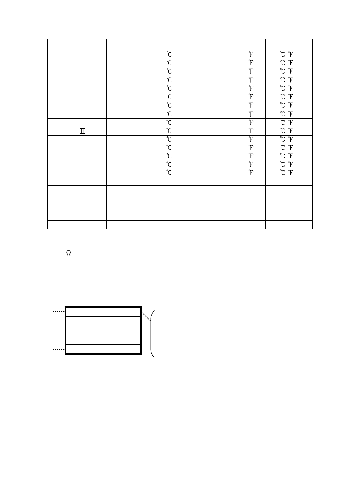
1.2 Rated input
CTi Automation - Phone: 800.894.0412 - Fax: 208.368.0415 - Web: www.ctiautomation.net - Email: info@ctiautomation.net
Input type Input range Resolution
K
J
–200 to 1370 –320 to 2500 1 ( )
–199.9 to 400.0
–200 to 1000
R 0 to 1760 0 to 3200 1 ( )
S 0 to 1760 0 to 3200 1 ( )
B 0 to 1820 0 to 3300 1 ( )
E
–200 to 800
T –199.9 to 400.0 –199.9 to 750.0 0.1 ( )
N –200 to 1300 –320 to 2300 1 ( )
PL- 0 to 1390 0 to 2500 1 ( )
C(W/Re5-26) 0 to 2315 0 to 4200 1 ( )
Pt100
JPt100
–199.9 to 850.0 –199.9 to 999.9 0.1 ( )
–200 to 850
–199.9 to 500.0 –199.9 to 900.0 0.1 ( )
–200 to 500
4 to 20mA DC –1999 to 9999 *1, *2 1
0 to 20mA DC –1999 to 9999 *1, *2 1
0 to 1V DC
0 to 10V DC
–1999 to 9999 *1 1
–1999 to 9999 *1 1
1 to 5V DC –1999 to 9999 *1 1
0 to 5V DC –1999 to 9999 *1 1
*1: For DC input, the input range and decimal point place can be changed.
*2: 50
shunt resistor (AKT4810, sold separately) must be connected between input
terminals
1.3 How to read the rated label
The rated label is attached to the case.
(1)
A K T 9 1 1 1 1 0 0 1
(2)
No.
–199.9 to 750.0 0.1 ( )
–320 to 1800 1 ( )
–320 to 1500 1 ( )
–300 to 1500 1 ( )
–300 to 900 1 ( )
(e.g.)
Supply voltage: 100 to 240V AC
Multi-input
Relay contact output
A1 output
Heating/Cooling control is not added.
Heater burnout alarm is not added.
Serial communication is added.
(1) Model number, supply voltage, input type, output type, etc. are entered.
(2) Lot number is entered.
7
Page 8
2. Name and functions of the sections
CTi Automation - Phone: 800.894.0412 - Fax: 208.368.0415 - Web: www.ctiautomation.net - Email: info@ctiautomation.net
(Fig. 2-1)
(1) PV display
(2) SV display
(3) SV1 indicator
(4) SV2 indicator
(5) OUT1 indicator
(6) OUT2 indicator
(7) HB indicator
(1)
(2)
(3)
(4)
(5)
(6)
(7)
(12)
(15)
(13)
Indicates the PV (process variable) with a red LED.
Indicates the SV (main set value) or MV (manipulated variable) with a green LED.
The green LED lights when SV1 is selected.
The green LED lights when SV2 is selected.
When OUT1 or Heating output is on, the green LED lights.
(For the DC current output type, this flashes corresponding to the output manipulated
variable in 0.25 second cycles)
When OUT2 is on, the yellow LED lights.
(For the DC current output type, this flashes corresponding to the output manipulated
variable in 0.25 second cycles)
When Heater burnout alarm output or sensor burnout alarm output is on, the red LED lights.
(When Heater burnout alarm is added and if indication is overscale or underscale,
the red LED lights as well)
(8)
(9)
(10)
(11)
(14)
8
Page 9

(8) A T indicator
CTi Automation - Phone: 800.894.0412 - Fax: 208.368.0415 - Web: www.ctiautomation.net - Email: info@ctiautomation.net
The yellow LED flashes during auto-tuning or auto-reset.
(9) TX/RX indicator
The yellow LED flashes during Serial communication.
(10) A1 indicator
When A1 output is on, the red LED lights.
(1 1) A2/LA indicator
When A2 output is on, the red LED lights.
(12) Increase key: Increases the numeric value.
(13) Decrease key: Decreases the numeric value.
(14) Mode key: Selects the setting mode or registers the set value.
(By pressing the Mode key, the set value or selected value can be registered.)
(15) OUT/OFF key
• If OUT/OFF function is selected during OUT/OFF function selection, the control out put
is turned on or off.
Once the control output OFF function is enabled, the function cannot be released ev en
if the power to the instrument is turned OFF and turned ON again.
To cancel the function, press the OUT/OFF key again for approx. 1 second.
If Auto/Manual control function is selected from OUT/OFF function selection, automatic
•
control is performed when the power to the controller is turned on. In this status, if the
OUT/OFF key is pressed, the automatic control output is switched to manual control
output and vice versa. However, this function can be switched only in the PV/SV
display mode.
Notice
When setting the specifications and functions of this controller, connect terminals 2
and 3 for power source first, then set them referring to “5. Setup” before performing “3.
Mounting to the control panel” and “4. Wiring”.
9
Page 10
3. Mounting to the control panel
(*)
CTi Automation - Phone: 800.894.0412 - Fax: 208.368.0415 - Web: www.ctiautomation.net - Email: info@ctiautomation.net
3.1 Site selection
This instrument is intended to be used under the following environmental
conditions (IEC61010-1): Overvoltage category
, Pollution degree 2
Ensure the mounting location corresponds to the following conditions:
(1) A minimum of dust, and an absence of corrosive gases
(2) No flammable, explosive gases
(3) No mechanical vibrations or shocks
(4) No exposure to direct sunlight, an ambient temperature of 0 to 50
(32 to 122
) that does not change rapidly
(5) An ambient non-condensing humidity of 35 to 85%RH
(6) No large capacity electromagnetic switches or cables through which large
current is flowing
(7) No water, oil or chemicals or where the vapors of these substances can
come into direct contact with the unit
3.2 External dimensions (Unit: mm)
Gasket
Screw type mounting bracket
Terminal cover
96
96
(Fig. 3.2-1)
3.3 Panel cutout (Unit: mm)
130
11.5
n×96-3
98.5
104.5
(*): When terminal cover is used
0
+0.8
□92
+0.5
0
Lateral close mounting
n: Number of units mounted
91
106.2
IP66 specification may be compromised, and all
□92
+0.8
0
Caution: If lateral close mounting is used for the controller,
warranties will be invalidated.
(Fig. 3.3-1)
10
Page 11
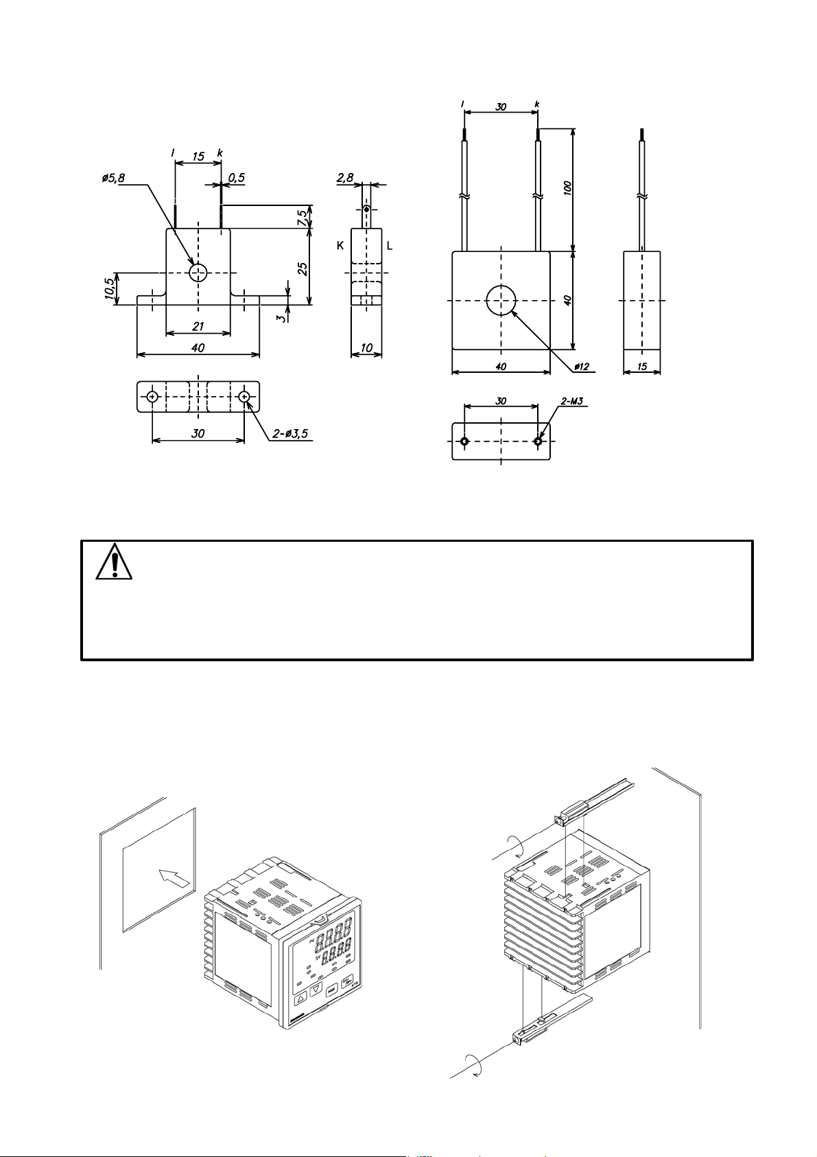
3.4 CT (Current transformer) external dimensions (Unit: mm)
CTi Automation - Phone: 800.894.0412 - Fax: 208.368.0415 - Web: www.ctiautomation.net - Email: info@ctiautomation.net
AKT4815 (for 5A, 10A and 20A) AKT4816 (for 50A)
(Fig. 3.4-1)
3.5 Mounting
As the case is made of resin, do not use excessive force while screwing in the
mounting bracket, or the case or screw type mounting bracket could be damaged.
The torque is approximately 0.12N•m.
Mount the controller vertically to the flat, rigid panel to ensure it adheres to the
Dust-proof/Drip-proof specification (IP66).
Mounting panel thickness: 1 to 15mm.
Insert the instrument from the front side of the panel.
Attach the mounting bracket by the holes at the top and bottom of the case and sec u re
in place with the sc re ws .
Notice
(Fig. 3.5-1)
11
Page 12

4. Wiring
CTi Automation - Phone: 800.894.0412 - Fax: 208.368.0415 - Web: www.ctiautomation.net - Email: info@ctiautomation.net
Turn the power supply to the instrument off before wiring or checking.
Working or touching the terminal with the power switched on may result in
severe injury or death due to Electric Shock.
Moreover, the instrument must be grounded before the power supply to the
instrument is turned on.
4.1 Terminal arrangement
• OUT1 : Control output 1
(Heating output)
• OUT2 : Control output 2
(Cooling output)
• RELAY : Relay contact output
Warning
• V/A : Non-contact voltage
output/DC curren t ou tput
• A1 : Alarm 1 output
• A2 : Alarm 2 output
• HB : Heater burnout alarm
output
• RS-485: Serial communication
• SV 2 : 2nd SV
• CT : CT input
• TC : Thermocouple
• RTD : Resistance
temperature detector
• DC : DC current or
DC voltage
(Fig. 4.1-1)
12
Page 13
CTi Automation - Phone: 800.894.0412 - Fax: 208.368.0415 - Web: www.ctiautomation.net - Email: info@ctiautomation.net
• The terminal block of KT9 series is designed to be wired from the left side.
The lead wire must be inserted from the left side of the terminal, and fastened
with the terminal screw.
• Dotted lines show options.
• If A2 (option) and Heater burnout alarm (option) are applied together, use
terminals 12-13 for A2, and 9-10 for the Heater burnout alarm.
• If the Heating/Cooling control (option) and Heater burnout alarm (option) are
applied together, use terminals 9-10 for the Heating/Cooling control, and 12-13
for the Heater burnout alarm.
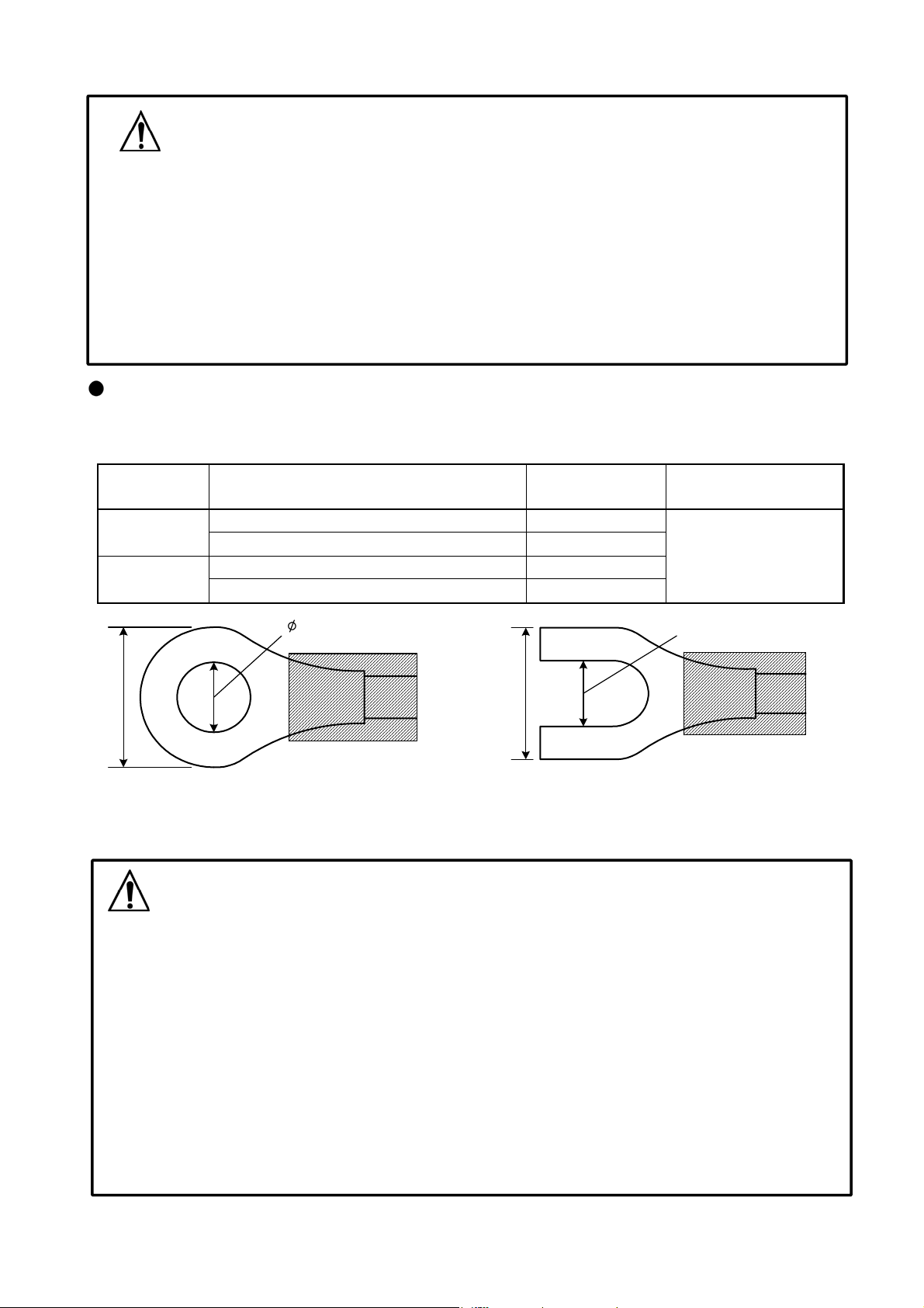
Lead wire solderless terminal
Use a solderless terminal with an insulation sleev e in which an M3 screw fits as shown
below.
Solderless
terminal
Y type
Round type
Notice
Nichifu Terminal Industries CO.,LTD. 1.25Y-3
Japan Solderless Terminal MFG CO.,LTD. VD1.25-B3A 0.6N•m
Nichifu Terminal Industries CO.,LTD. 1.25-3 Max. 1.0N•m
Japan Solderless Terminal MFG CO.,LTD. V1.25-3
Manufacturer Model Tightening torque
5.8mm or less
(Fig. 4.1-2)
4.2 Wiring examples
• Use a thermocouple and compensating lead wire according to the sensor input
specifications of this cont ro l l er.
• Use the 3-wire RTD according to t he sensor input sp ec ifi c ations of t h is cont r oll e r.
• This controller does not have built-in power switch, circuit breaker or fuse.
It is necessary to install them i n t he circuit near the external controller.
(Recommended fuse: Time-lag fuse, rated voltage 250V AC, rated current 2A)
• For a 24V AC/DC power source, do not confuse polarity when using direct current (DC).
• When using a relay contact output type, use a relay externally according to the
capacity of the load to protect the buil t-in relay contact .
• When wiring, keep the input wire (Thermoc ouple, RTD, etc.) away from AC sources
or load wires to avoid external interference.
• Use a thick wire (1.25 to 2.0mm
Notice
3.2mm
2
) for grounding.
3.2mm
5.8mm or less
13
Page 14
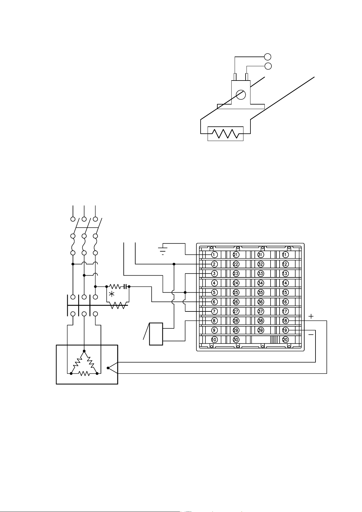
[Heater burnout alarm output]
CTi Automation - Phone: 800.894.0412 - Fax: 208.368.0415 - Web: www.ctiautomation.net - Email: info@ctiautomation.net
(1) This alarm is not available for detecting
heater current under phase control.
(2) This alarm is not available for detecting
3-phase heater current.
(3) Use the current transformer (CT) provided,
and pass one lead wire of the heater
circuit into the hole of the CT.
(4) When wiring, keep CT wire away from
CT
15
CT input terminals
16
Power source
any AC source and load wire to avoid
Heater
external interference. (Fig. 4.2-1)
[AKT9111100]
3-phase
100 to 240V AC
or 24V AC/DC
Electromagnetic
switch
Alarm unit
Heater
Electric furnace
Thermocouple
(Fig. 4.2-2)
*
To prevent the unit from harmful effects of unexpected high level noise, it is
recommended that a surge absorber be installed between the electromagnetic
switch coils.
• For a 24V AC/DC power source, do not confuse polarity when using direct current (DC).
14
Page 15
5. Setup
CTi Automation - Phone: 800.894.0412 - Fax: 208.368.0415 - Web: www.ctiautomation.net - Email: info@ctiautomation.net
For the thermocouple and RTD input, the sensor input charact ers and temperature unit
are indicated on the PV display and the input range high limit value is indicated on the SV
display for approx. 3 seconds after the power is turned on. See (Table 5-1).
For DC input, the sensor input characters are indicated on the PV display and the scaling
high limit value is indicated on the SV display. See (Table 5-1).
If any other value is set during the scaling high limit setting, the set value is indicated on
the SV display.
During this time, all outputs and the LED indicators are in OFF status.
Control will then start and the PV (process variable) will be indicated on the PV display
and SV1 or SV2 will be indicated on the SV display.
While control output OFF function is working,
release the function, press the OUT/OFF key for approx. 1 second.
To
(Table 5-1)
Sensor input
K
J
R
S
B
E
T
N
PL-
C (W/Re5-26)
Pt100
JPt100
4 to 20mA DC
0 to 20mA DC
0 to 1V DC
0 to 10V DC
1 to 5V DC
0 to 5V DC
PV display SV display PV display SV display
is indic ated on the PV display.
Scaling high limit value
15
Page 16

[
]
y
pp
5.1 Operation flow chart
Outline of operation procedure
Operation before running
[Step 1 Initial setting] : Set Input type, Alarm type, control action,
etc. in Auxiliary function setting mode 2.
[Step 2 Adjusting item] : Set PID values and Alarm values in the
Sub setting mode.
[Step 3 Lock setting] : Set the Set value Lock, SV high limit and SV low
[Step 4 Run setting] : Set SV1 (desired value) in the Main setting mode.
limit in Auxiliary function setting mode 1 (If Step 3
is not necessary, skip this step.)
Control output OFF function or
Auto/Manual control function
Press key for approx. 1sec.
PV/SV display
Alarm 1 (A1) setting procedure
[Numbers (1) to (5) are indicated on the flow chart.]
(1) [A1 type]: Select an alarm type
[If an alarm type except for
are indicated and they can be set if necessary.]
(2) [A1 action Energized/Deenergized]: Select Alarm 1 contact
output ON (Ene rgized:
(3) [A1 hysteresis]: Set A1 hysteresis.
(4) [A1 action delayed timer]: Set A1 action delayed time.
(If input enters alarm action range and setting times has passed,
the alarm is activated.)
(5) [A1 value]: Set action point of A1 output.
[Note] If an alarm type is changed, the alarm set value
becomes 0 (0.0). Therefore it is necessary to reset it.
Press the ke
Press the key
for approx. 3sec.
is selected, items (2) to (5)
) or OFF (Deenergized: ).
.
Output MV indication
Press the key.
[Main setting mode] [Sub setting mode]
SV1 (Desired value)
PV
SV
SV
SV2 (Desired value)
PV
Reverts to PV/SV display.
SV
SV
Explanation of key
: This means that
is pressed, the set
if
value is saved, and the
controller proceeds to the
next setting item.
PV
OUT1 proportional
PV SV
OUT2 proportional
PV SV
PV SV
PV SV
PV
OUT1 proportional
PV SV
OUT2 proportional
PV SV
(5)
PV SV
Press the while holding down the key.
AT/Auto-reset
SV
/
Selection
band
Set value
band
Set value
Integral time
Set value
Derivative time
Set value
ARW
SV
Set value
cycle
Set value
cycle
Set value
A1 value
Set value
• If AT is cancelled during the process,
PID values revert to previous value.
• Auto-reset is automatically cancelled
in 4 minutes.
• Set the value with , keys.
• ON/OFF action when set to 0 or 0.0
• Set the value with , keys.
• Available when Heating/Cooling
control (OUT2) is added
• Set the value with , keys.
• PD action when set to 0, and auto-
reset can be performed.
• Set the value with , keys.
• PI action when set to 0
• Set the value with , keys.
• Available for PID action
• Set the value with , keys.
• Not available for DC current output or
when OUT1 is ON/OFF action
• Set the value with , keys.
• Not available when OUT2 is ON/OFF
action
• Set the value with , keys.
• Not available if
during A1 type selection
is selected
Press for a
Auxiliary function setting mode 1
Set value Lock
PV
PV
PV
Sensor correction
PV
Communication protocol
PV SV
Instrument number
PV
Communication speed
PV
PV
PV
SV
Selection
SV high limit
SV
Set value
SV low limit
SV
Set value
SV
Set value
Selection
SV
Set value
SV
Selection
Parity
SV
Selection
Stop bit
SV
Selection
rox. 3sec while holdingdown .
• Make a selection with
keys.
• If Lock 1 or Lock 2 is selected,
AT or Auto-reset does not work.
• Be sure to select Lock 3 when
using Serial communication.
• Set the value with
• Set the value with , keys.
• Set the value with
• Make a selection with , keys.
• Not available for
• Set the value with , keys.
• Make a selection with , keys.
• Make a selection with , keys.
• Not available if
during Communication protocol
selection
•
Make a selection with , keys.
• Not available if
during Communication protocol
selection
,
, keys.
, keys.
indication
is selected
is selected
A2 value
PV SV
Set value
• Set the value with , keys.
• Not available if
during A2 type selection
is selected
Reverts to the PV/SV display.
Setting items with dotted lines are optional
Heater burnout alarm value
PV
.
SV
Set value
• Set the value with
• OFF when set to 0.0
, keys.
and they appear only when the options are
added.
Reverts to the PV/SV display.
16
Page 17

[
Input type (character indication) and range
K –200 to 1370 :
–199.9 to 400.0
J –200 to 1000
R 0 to 1760
S 0 to 1760
B 0 to 1820
E –200 to 800
T –199.9 to 400.0
N –200 to 1300
0 to 1390 :
PLC
(W/Re5-26) 0 to 2315 :
Pt100 –199.9 to 850.0 :
JPt100 –199.9 to 500.0 :
Pt100 –200 to 850
JPt100 –200 to 500
:
:
:
:
:
:
:
:
:
:
K –320 to 2500
–199.9 to 750.0 :
J –320 to 1800
R 0 to 3200 :
S 0 to 3200 :
B 0 to 3300 :
E –320 to 1500 :
T –199.9 to 750.0 :
N –320 to 2300 :
PL- 0 to 2500 :
C(W/Re5-26) 0 to 4200 :
Pt100 –199.9 to 999.9 :
JPt100 –199.9 to 900.0 :
Pt100 –300 to 1500
JPt100 –300 to 900 :
4 to 20mA DC –1999 to 9999:
0 to 20mA DC –1999 to 9999:
0 to 1V DC –1999 to 9999:
0 to 5V DC –1999 to 9999:
1 to 5V DC –1999 to 9999:
0 to 10V DC –1999 to 9999:
:
:
:
Alarm type
High limit alarm: The alarm action is deviation setting from the SV. The alarm is activated
if the input value reaches the high limit set value. Character indication:
Low limit alarm: The alarm action is
deviation setting to the SV. The alarm is activated
if the input value goes under the low limit set value. Character indication:
High/Low limits alarm: Combines High limit and Low limit alarm actions. When input value
reaches high limit set value or goes under the low limit set value, the alarm is
activated. Character indication:
High/Low limit range alarm: When input value is between the high limit set value and low
limit set value, the alarm is activated. Character indication:
Process alarm: Within the scale range of the controller, alarm action points can be set
at random and if the input reaches the randomly set action point, the alarm is
activated.
Character indication: Process high alarm
, Process low alarm
Alarm with standby function: When the power to the controller is turned on, even if the input
enters the alarm action range, the alarm is not activated. (If the controller is
allowed to keep running, once the input exceeds the alarm action point, the
standby function will be released.)
Character indication:
High limit alarm with standby :
Low limit alarm with standby :
High/Low limits alarm with standby :
PV
Scaling high limit
PV
Scaling low limit
PV
Decimal point place
PV
PV
OUT1 high limit
PV
Press the and keys for approx. 3sec.
Auxiliary function setting mode 2]
Input type
SV
Selection
SV
Set value
SV
Set value
SV
Selection
PV filter time
constant
SV
Set value
SV
Set value
• Make a selection with the
• Default value:
• Set the value with the
• Available for DC current, DC voltage input
• Set the value with the
• Available for DC current, DC voltage input
• Make a selection with the
• Available for DC current, DC voltage input
• Set the value with the
• Set the value with the
• Not available for ON/OFF action
, keys.
, keys.
, keys.
, keys.
, keys.
, keys.
(1)
PV
PV
A1 action Energized/
(2)
Deenergized setting
PV
A2 action Energized/
Deenergized
PV
(3)
(4)
A1 hysteresis
PV SV
A2 hysteresis
PV SV
A1 action delayed
PV SV
A1 type
SV
A2 type
SV
SV
SV
timer
Selection
Selection
Selection
Selection
Set value
Set value
Set value
• Make a selection with the , keys.
• Default value:
• Make a selection with the , keys.
• Available when A2 is added
• Make a selection with the , keys.
• Not available if
is selected during A1
type selection
• Make a selection with the , keys.
• Not available if
is selected during A2
type selection
• Set the value with the , keys.
• Not available if
type selection
• Set the value with the , keys.
• Not available if
type selection
is selected during A1
is selected during A2
• Set the value with the , keys.
• Not available if
is selected during A1
type selection
OUT1 low limit
PV
OUT1 ON/OFF action
hysteresis
PV
OUT2 action mode
PV
PV
PV
PV
OUT2 high limit
OUT2 low limit
Overlap/Dead band
OUT2 ON/OFF action
hysteresis
PV
SV
Set value
SV
Set value
SV
Selection
SV
Set value
SV
Set value
SV
Set value
SV
Set value
• Set the value with the
• Not available for ON/OFF action
• Set the value with the
, keys.
, keys.
• Available for ON/OFF action
• Make a selection with the , keys.
• Available when Heat/Cool control (OUT2) is added
• Set the value with the
• Available when Heat/Cool control (OUT2) is added
• Set the value with the
, keys.
, keys.
• Available when Heat/Cool control (OUT2) is added
• Set the value with the
, keys.
• Available when Heat/Cool control (OUT2) is added
• Set the value with
, keys.
• Available when Heat/Cool control (OUT2) is added
17
A2 action delayed
timer
PV SV
Direct/Reverse control
PV
PV SV
Setting item not used
PV SV
SV2 indication
PV
AT bias
Set value
SV
Selection
Set value
Set value
SV
Selection
Output status selection
when input abnormal
PV
OUT/OFF key function
PV
SV
Selection
SV
Selection
Reverts to the PV/SV display.
• Set the value with the , keys.
• Not available if
is selected during A2
type selection
• Make a selection with the , keys.
• Default value:
• Set the value with the , keys.
• Available for thermocouple, RTD input
• Do not set this item even if is indicated
on the PV display.
• Selects whether SV2 is indicated or not.
• Default value:
(Indication)
• Make a selection with the , keys.
• Available only when input is DC current and DC
voltage with DC current output.
• Make a selection with the , keys.
Page 18

5.2 Main setting mode
CTi Automation - Phone: 800.894.0412 - Fax: 208.368.0415 - Web: www.ctiautomation.net - Email: info@ctiautomation.net
The main setting mode can be selected by pressing the
The SV can be increased or decreased by pressing the
The SV is registered by pressing the
display mode.
Character
(PV display)
5.3 Output MV indication
Output MV (manipulated variable) indication
• In the PV/SV display mode, if the
MV is indicated on the SV display.
While the output MV is indicated, the 1st decimal point from t he right on the SV
display flashes in 0.5 second cycles.
By pressing the
5.4 Sub setting mode
The sub setting mode can be selected by pressing the
the
The set value can be increased or decreased by pressing the
The set value is registered by pressing the
selected.
Character
(PV display)
/
Name, Function, Setting range
SV1 0
• Sets SV1.
• Setting range: SV low limit to SV high limit, or
scaling low limit value to scaling high limit value
SV2 0
• Sets SV2.
• Not available if Serial communication (option) is added.
• Setting range: SV low limit to SV high limit, or
scaling low limit value to scaling high limit value
key again, the unit reverts to the PV/SV display mode.
key.
Name, Function, Setting range
AT setting/Auto-reset setting Cancel
• Sets AT (auto-tuning) or Auto-reset (offset correction).
• Auto-reset can be performed only in PD or P action.
(Auto-reset cannot be performed when the control action is PID, PI
or ON/OFF action)
[Auto-tuning]
• If Auto-tuning “Perform” is selected and the
the AT indicator flashes and the unit reverts to the PV/SV display
mode.
• When Auto-tuning is finished, the AT indicator is turned off and P, I, D,
ARW values are automatically set.
• During auto-tuning, none of the settings can be carried out.
• If Auto-tuning is cancelled during the process, P, I, D, ARW values
return to the previous value.
• If OUT/OFF key is pressed during auto-tuning, control output OFF
function activates, and pressing the OUT/OFF key again cancels the
PID auto-tuning.
• If PID auto-tuning does not finish in 4 hours after starting, PID
auto-tuning is cancelled automatically.
k ey, and the unit reverts to the PV/SV
key is pressed for 3 seconds, the output
k ey, then the next setting item is
key.
or key.
Default value
(SV display)
key while holding down
or key.
Default value
(SV display)
key is pressed,
18
Page 19

CTi Automation - Phone: 800.894.0412 - Fax: 208.368.0415 - Web: www.ctiautomation.net - Email: info@ctiautomation.net
[Auto-reset]
• If auto-reset “Perform” is selected and the
k ey is press ed,
the AT indicator flashes and the unit reverts to the PV/SV display
mode.
• If auto-reset is performed, offset correction immediately starts.
• To prevent key misoperation, other settings cannot be performed for 4
minutes after auto-reset starts.
• After auto-reset is completed, the AT indicator is turned off and the
reset value is automatically set.
OUT1 proportional band setting 10
• Sets OUT1 proportional band.
The control action becomes ON/OFF action when set to 0 or 0.0.
• Setting range: 0 to 1000
With a decimal point, 0.0 to 999.9
(0 to 2000 )
(0.0 to 999.9 )
DC input: 0.0 to 100.0%
OUT2 proportional band setting 1.0 times
• Sets OUT2 proportional band.
OUT2 becomes ON/OFF action when set to 0.0.
• Available only when Heating/Cooling control (option) is added.
• Setting range: 0.0 to 10.0 (multiplying factor to OUT1 proportional
band)
Integral time setting 200 seconds
• Sets the integral time.
Setting the value to 0 disables the function (PD action).
• Setting range: 0 to 1000 seconds
Derivative time setting
50 seconds
• Sets the derivative time.
Setting the value to 0 disables the function (PI action).
• Setting range: 0 to 300 seconds
ARW (Anti-reset windup) setting 50%
• Sets the anti-reset windup.
• Available only for PID action.
• Setting range: 0 to 100%
OUT1 proportional cycle setting
• Sets OUT1 proportional cycle.
Relay contact output: 30sec
Non-contact voltage output: 3sec
Not available for ON/OFF action and DC current output type
• With the relay contact output type, if the proportional cycle time
is decreased, the frequency of the relay action increases and
the life of the relay contact is shortened.
• Setting range: 1 to 120 seconds
OUT2 proportional cycle setting
• Sets OUT2 proportional cycle.
Relay contact output: 30sec
Non-contact voltage output: 3sec
Not available for ON/OFF action and DC current output type
• Available only when Heating/Cooling control (option) is added.
• Setting range: 1 to 120 seconds
19
Page 20

CTi Automation - Phone: 800.894.0412 - Fax: 208.368.0415 - Web: www.ctiautomation.net - Email: info@ctiautomation.net
A1 value setting 0
• Sets the action point for A1 output.
Set ting the value to 0 or 0.0 disables the function.
(excluding Proces s high and Proces s low alarm)
• Not available if No alarm action is selected during A1 type selection.
• Setting range: See (Table 5.4-1).
A2 value setting
• Sets the action point for A2 output.
Set ting the value to 0 or 0.0 disables the function.
0
(excluding Process high and low alarm)
• Not available if A2 (option) is not added or if No alarm action is
selected during A2 type selection.
• Setting range and default value are the same as those of A1 value setting.
.
and
measured
current
value are
displayed
alternately.
HB (Heater burnout alarm) value setting 0.0A
• Sets the heater current value for Heater burnout alarm.
• Available only when the Heater burnout alarm (option) is added.
• When OUT1 is OFF, heater current value shows the previous value as
when OUT1 was ON.
• Setting the value to 0.0 disables the function.
I t is recommended to set approx. 80% of the heater current value
(set value) considering the voltage fluctuation.
• Upon returning to set limits, the alarm will stop.
• Setting range: Rating 5A: 0.0 to 5.0A Rating 10A: 0.0 to 10.0A
Rating 20A: 0.0 to 20.0A Rating 50A: 0.0 to 50.0A
Setting range of A1 and A2
(Table 5.4-1)
Alarm type Setting range
High limit alarm –Input span to input span ( ) *1
Low limit alarm –Input span to input span ( ) *1
High/Low limits alarm 0 to input span ( ) *1
High/Low limit range alarm 0 to input span ( ) *1
Process high alarm Input range low limit to input range high limit *2
Process low alarm Input range low limit to input range high limit *2
High limit alarm with standby –Input span to input span ( ) *1
Low limit alarm with standby –Input span to input span ( ) *1
High/Low limits alarm with standby 0 to input span ( ) *1
• When the input has a decimal point, negative low limit value is –199.9, and positive
high limit value is 999.9.
• All alarm types except Process alarm are
deviation setting from the SV.
*1: For DC input, the input span is the same as the scaling span.
*2: For DC input, input range low (or high) limit value is the same as the scaling low
(or high) limit value.
5.5 Auxiliary function setting mode 1
In the PV/SV display mode, if the
holding down the
key, Auxiliary function setting mode 1 can be selected.
The set value can be increased or decreased by pressing the
If the
key is pressed, the set value is registered and the next setting item is
key is pressed for approx. 3 seconds while
or key.
selected.
20
Page 21

Character
CTi Automation - Phone: 800.894.0412 - Fax: 208.368.0415 - Web: www.ctiautomation.net - Email: info@ctiautomation.net
(PV display)
Name, Function, Setting range
Default value
(SV display)
Set value lock selection Unlock
• Locks the set value to prevent setting errors
The setting item to be locked depends on the selection.
• PID auto-tuning or auto-reset does not work if Lock 1 or Lock 2 is selected.
• When selecting Lock, select Lock 1, Lock 2 or Lock 3 after setting the
necessary items in the status Unlock.
•
(Unlock): All set values are changeable.
(Lock 1): None of the set values can be changed.
(Loc k 2): Only main setting mode can be changed.
(Lock 3): All set values except input type can be changed. However,
they return to their previo us value after the power is turned off because
they are not written in the non-volatile memory. Be sure to use
Lock 3 when changing the set value frequently via communication.
(When Lock 1 or Lock 2 is selected, if the value changed by the
communication function is the same as the previous one, it is not
written in the non-volatile memory.) Do not change any setting item
in Auxiliary function setting mode 2. If any item in the mode is changed,
it will affect other setting items such as SV and Alarm value.
SV high limit setting
1370
• Sets SV high limit.
• Setting range: SV low limit to input range high limit value
DC input: SV low limit to scaling high limit value
(The placement of the decimal point follows the selection)
SV low limit setting –200
• Sets SV low limit.
• Setting range: Input range low limit value to SV high limit
Sensor correction setting 0.0
DC input: Scaling low limit value to SV high limit
(The placement of the decimal point follows the selection)
• Sets correction value for the sensor.
• Setting range: –100.0 to 100.0
( ), For DC input, –1000 to 1000
(The placement of the decimal point follows the selection)
Communication protocol selection
• Selects the communication protocol.
• Available only when Serial communication (option) is applied.
• Not available if
• Modbus ASCII mode:
is indicated
, Modbus RTU mode:
Instrument number setting 0
• Sets the instrument number. (Communication cannot be carried out
unless an instrument number is individually set when communicating
by connecting plural instruments in serial communication.)
• Available only when Serial communication (option) is added.
• Setting range: 0 to 95
Communication speed selection 9600bps
• Selects a speed equal to that of the host computer.
(Communication cannot be performed unless the speeds are equal)
• Available only when Serial communication (option) is added.
• 2400bps:
, 4800bps: , 9600bps: , 19200bps:
21
Page 22

CTi Automation - Phone: 800.894.0412 - Fax: 208.368.0415 - Web: www.ctiautomation.net - Email: info@ctiautomation.net
Parity selection Even parity
• Selects the parity.
• Not available if Serial communication (option) is not added or
if
is selected during Communication protocol selection.
• No parity:
Stop bit selection 1
• Selects the stop bit.
• Not available if Serial communication (option) is not added or
if
is selected during Communication protocol selection.
• Selecting item:
5.6 Auxiliary function setting mode 2
In the PV/SV display mode, if the
seconds, Auxiliary function setting mode 2 can be selected.
, Even parity: , Odd parity:
(1) or (2)
and keys are pressed for approx. 3
The set value can be increased or decreased by pressing the
If the
key is pressed, the set value is registered and the next setting item is
or key.
selected.
Character
(PV display)
Name, Function, Setting range
Input type selection
Default value
(SV display)
K (–200 to
• The input type can be selected from
thermocouple (10 types), RTD (2 types), DC current (2 types ) and
DC voltage (4 types) and the unit
/ .
Input type Input range
K
–200 to 1370 : –320 to 2500 :
–199.9 to 400.0
: –199.9 to 750.0 :
J –200 to 1000 : –320 to 1800 :
R 0 to 1760 : 0 to 3200 :
S 0 to 1760 : 0 to 3200 :
B
0 to 1820
: 0 to 3300 :
E –200 to 800 : –320 to 1500 :
T –199.9 to 400.0 : –199.9 to 750.0 :
N –200 to 1300 : –320 to 2300 :
PL- 0 to 1390 : 0 to 2500 :
C(W/Re5-26) 0 to 2315 : 0 to 4200 :
Pt100
JPt100
–199.9 to 850.0 : –199.9 to 999.9 :
–200 to 850
–199.9 to 500.0
–200 to 500
: –300 to 1500 :
:
–199.9 to 900.0 :
: –300 to 900 :
4 to 20mA DC –1999 to 9999:
0 to 20mA DC –1999 to 9999:
0 to 1V DC –1999 to 9999:
0 to 10V DC –1999 to 9999:
1 to 5V DC –1999 to 9999:
0 to 5V DC –1999 to 9999:
1370
)
22
Page 23

CTi Automation - Phone: 800.894.0412 - Fax: 208.368.0415 - Web: www.ctiautomation.net - Email: info@ctiautomation.net
Scaling high limit setting 9999
• Sets scaling high limit value.
• Available only for the DC input
• Setting range: Scaling low limit value to input range high limit value
(The placement of the decimal point follows the selection)
Scaling low limit setting
–1999
• Sets scaling low limit value.
• Available only for the DC input
• Setting range: Input range low limit value to scaling high limit value
(The placement of the decimal point follows the selection)
Decimal point place selection No decimal point
• Selects a decimal point place.
• Not available for thermocouple or RTD input
• No decimal point :
1 digit after decimal point :
2 digits after decimal point :
3 digits after decimal point :
PV filter time constant setting 0.0 seconds
• Sets PV filter time constant.
If the value is set too large, it adversely affects control result due to
the delay of response.
• Setting range: 0.0 to 10.0 seconds
OUT1 high limit setting 100%
• Sets the high limit value of OUT1.
Not available if OUT1 is ON/OFF action
• Setting range: OUT1 low limit value to 105%
Setting higher than 100% is effective to DC current output type.
OUT1 low limit setting 0%
• Sets the low limit value of OUT1.
Not available if OUT1 is ON/OFF action
• Setting range: –5% to OUT1 high limit value
Setting less than 0% is effective to DC current output type.
OUT1 ON/OFF action hysteresis setting 1.0
• Sets ON/OFF action hysteresis for OUT1.
Available only when OUT1 is ON/OFF action
• Setting range: 0.1 to 100.0
( )
For DC input, 1 to 1000 (The placement of the decimal
point follows the selection)
OUT2 action mode selection Air cooling
• Selects a cooling action from Air cooling, Oil cooling and Water
cooling.
Not available if OUT2 is ON/OFF action or if Heating/Cooling control
(option) is not applied
•
: Air cooling (Linear characteristic)
: Oil cooling (The 1.5th power of the linear characteristic)
: Water cooling (The 2nd power of the linear characteristic)
23
Page 24

CTi Automation - Phone: 800.894.0412 - Fax: 208.368.0415 - Web: www.ctiautomation.net - Email: info@ctiautomation.net
OUT2 high limit setting 100%
• Sets the high limit value of OUT2.
• Not available if OUT2 is ON/OFF action or if Heating/Cooling control
(option) is not applied
• Setting range: OUT2 low limit value to 105%
(Setting higher than 100% is effective to DC current output type.)
OUT2 low limit setting 0%
• Sets the low limit value of OUT2.
• Not available if OUT2 is ON/OFF action or if Heating/Cooling control
(option) is not applied
• Setting range: –5% to OUT2 high limit value
(Setting less than 0% is effective to DC current output type.)
Overlap band/Dead band setting 0.0
• Sets overlap band and dead band value for OUT1 and OUT2.
+ Set value: Dead band
– Set value: Overlap band
• Not available if OUT2 is ON/OFF action or if Heating/Cooling control
(option) is not applied
• Setting range: –100.0 to 100.0
( )
DC input: –1000 to 1000 (The placement of the decimal
point follows the selection)
OUT2 ON/OFF action hysteresis setting 1.0
• Sets ON/OFF action hysteresis for OUT2.
• Available only when Heating/Cooling control (option) is applied
• Setting range: 0.1 to 100.0
( )
For DC input, 1 to 1000 (The placement of the decimal
point follows the selection)
A1 type selection
• Selects A1 type.
No alarm
action
• Selecting item
No alarm action :
High limit alarm :
Low limit alarm :
High/Low limits alarm :
High/Low limit range alarm :
Process high alarm :
Process low alarm :
High limit alarm with standby :
Low limit alarm with standby :
High/Low limits alarm with standby:
24
Page 25

CTi Automation - Phone: 800.894.0412 - Fax: 208.368.0415 - Web: www.ctiautomation.net - Email: info@ctiautomation.net
A2 type selection No alarm action
• Selects A2 type.
• Available only when A2 (option) is applied
• The selecting item is the same as those of A1 type selection.
A1 action Energized/Deenergized selection
Energized
• Selects A1 action Energized/Deenergized.
• Not available if No alarm action is selected during A1 type selection
• Selecting item
Energized:
A2 action Energized/Deenergized selection
Deenergized:
Energized
• Selects A2 action Energized/Deenergized.
• Not available if No alarm action is selected during A2 type selection
or if A2 (option) is not added
• The selecting item is the same as those of A1 action Energized/
Deenergized selection.
A1 hysteresis setting 1.0
• Sets A1 hysteresis.
• Not available if No alarm action is selected during A1 type selection
• Setting range: 0.1 to 100.0
( )
For DC input, 1 to 1000 (The placement of the decimal
point follows the selection)
A2 hysteresis setting 1.0
• Sets A2 hysteresis.
• Not available if No alarm action is selected during A2 type selection
or if A2 (option) is not added
• The setting range is the same as those of A1 hysteresis setting.
A1 action delayed timer setting 0 seconds
• Sets the action delayed timer for A1.
The Alarm is activated when the setting time has elapsed after the input
ent ers the alarm action range.
• Not available if No alarm action is selected during A1 type selection
• Setting range: 0 to 9999 seconds
A2 action delayed timer setting 0 seconds
• Sets the action delayed timer for A2.
The Alarm is activated when the setting time has elapsed after the input
ent ers the alarm action range.
• Not available if No alarm action is selected during A2 type selection
or if A2 (option) is not added
• The setting range is the same as those of A1 action delayed timer
setting.
25
Page 26

CTi Automation - Phone: 800.894.0412 - Fax: 208.368.0415 - Web: www.ctiautomation.net - Email: info@ctiautomation.net
Direct/Reverse control action selection
• Selects either Direct (Cooling) or Reverse (Heating)
Reverse
(Heating) action
control action.
• Selecting item
Reverse (Heating):
AT bias setting 20
Direct (Cooling):
• Sets the bias value for performing PID auto-tuning.
• Not available for DC input
• Setting range: 0 to 50
With a decimal point,0.0 to 50.0
Setting item not used
(0 to 100 )
(0.0 to 100.0 )
When Serial communication (option) is applied, this item appears.
However, do not set this item.
SV2 indication selection Indication
• Selects whether SV2 is indicated or not.
• Selecting item
(Indication) (No indication)
Output status selection when input abnormal Output OFF
• Selects the output status of OUT1 and OUT2 (option) when DC input is
overscale or underscale. See “Input abnormality indication” on pages 40, 41.
• Available only for DC current output with DC input
•
: OFF(4mA) or OUT1(OUT2) low limit
: Outputs a value between OFF(4mA) and ON(20mA) or between
OUT1(OUT2) low limit value and OUT1(OUT2) high limit value,
depending on a deviation.
OUT/OFF key function selection
• Selects the OUT/OFF key function.
OUT/OFF
function
• Selecting item
(OUT/OFF function), (Auto/Manual control function)
ARW function
ARW (Anti-reset windup) prevents overshoot caused by the integral action. The smaller
the ARW value, the less the overshoot caused by the integral action in the transition
status, however it takes time until stabilization.
Sensor correction function
This corrects the input value from the sensor. When a sensor cannot be set at a
location where control is desired, the sensor measuring temperature may deviat e from
the temperature in the controlled location. When controlling with plural controllers,
the accuracy of sensors affects the control.
Therefore, sometimes the measured temperatures (input value) do not concur. In such a
case, the control can be set at the desired temperature by adjusting t he input value of
sensors.
SV1/SV2 external selection
SV1 or SV2 can be selected by the external operation.
• Between terminals 14 and 17 open: SV1 can be selected.
• Between terminals 14 and 17 closed: SV2 can be selected.
• Set value memory number cannot be changed during setting mode or PID auto-tuning.
26
Page 27

Energized/Deenergized function
CTi Automation - Phone: 800.894.0412 - Fax: 208.368.0415 - Web: www.ctiautomation.net - Email: info@ctiautomation.net
[If the alarm action Energized is selected]
When the alarm output indicator is lit, the alarm output (terminals 7-8 or 12-13) is
conducted (ON). When the alarm output indicator is unlit, the alarm output is not
conducted (OFF). See (Fig. 5.6-1).
[If the alarm action Deenergized is selected]
When the alarm output indicator is lit, the alarm output (terminals 7-8 or 12-13) is not
conducted (OFF). When the alarm output indicator is unlit, the alarm output is
conducted (ON). See (Fig. 5.6-2).
A1 hysteresis
A1 hysteresis
ON
ON
OFF
SV setting + A1 set point
OFF
SV setting
+ A1 set point
High limit alarm (When Energized is set) High limit alarm (When Deenergized is set)
(Fig. 5.6-1) (Fig. 5.6-2)
5.7 Control output OFF function
Control output OFF function [
]
• A function to pause the control action or turn the control output of the unused
ins trument of the plural units OFF even if the power to the instrument is supplied.
[
] is indicated on the PV display while the function is working.
• Once the Control output OFF function is enabled, the function cannot be released
even if the power to the instrument is turned OFF and ON again.
To cancel the function, press the
key again for approx. 1 second.
5.8 Auto/Manual control function
PV/SV display
mode
(Manual control)
• To use this function, it is necessary to select Auto/Manual
c ontrol function during the OUT/OFF key function selection.
• First, press the
key.
The MV (manipulated variable) on the SV display can be
increased or decreased by pressing the
or key
and the control is performed.
• The 1st decimal point from the right on the SV display flashes.
• By pressing the
key again, the mode reverts to the
PV/SV display (automatic control) mode.
(When the power supply to the instrument is turned on,
automatic control starts)
27
Page 28

6. Running
CTi Automation - Phone: 800.894.0412 - Fax: 208.368.0415 - Web: www.ctiautomation.net - Email: info@ctiautomation.net
After the controller is mounted to the cont ro l panel and wiring is c ompleted, operat e t he
unit following the procedures below.
(1) Turn the power supply to the KT9 Series ON.
For approx. 3 seconds after the power is switched ON, sens or input charact ers and
temperature unit are indicated on the PV display, and the input range high limit value
is indicated on the SV display. See (Table 6-1).
For the DC input, for appro x. 3 second s after the power is switched ON, sensor input
characters are indicated on the PV display , and the scaling high limit value is indicated
on the SV display. See (Table 6-1).
However, if the scaling high limit value has been changed during the Scaling high limit
setting, the changed value is indicated on the SV display.)
(During this time, all outputs and the LED indicators are in OFF status)
After that, the PV (process variable) is indicated on the PV display, and SV1 or
SV2 is indicated on the SV display.
(When the Control output OFF function is working, “
PV display)
(Table 6-1)
Sensor input
K
J
R
S
B
E
T
N
PL-
C (W/Re5-26)
Pt100
JPt100
4 to 20mA DC
0 to 20mA DC
0 to 1V DC
0 to 10V DC
1 to 5V DC
0 to 5V DC
PV display SV display PV display SV display
Scaling high limit value
” is indicated on the
(2) Input each set value.
Input each set value, referring to “5. Setup”.
(3) Turn the load circuit power ON.
Control action starts so as to keep the control target at the SV.
28
Page 29

7. Action explanation
CTi Automation - Phone: 800.894.0412 - Fax: 208.368.0415 - Web: www.ctiautomation.net - Email: info@ctiautomation.net
7.1 OUT1 action
Control action
Relay contact
output
Non-contact
voltage output
DC current
output
Indicator
(OUT1) Green
: Acts ON (lit) or OFF (unlit).
7.2 Heater burnout alarm action (option)
Heater burnout
alarm action
Heater burnout
alarm output
Indicator
(HB) red
When Heating/Cooling control (option) is applied,
use terminals 12 and 13 for the Heater burnout alar m out put.
Heating (reverse) action Cooling (direct) action
Proportional band
ON
OFF
SV setting
4
H
5
C
6
L
Cycle action is performed according to deviation.
5
+
12V DC
6
-
Cycle action is performed according to deviation.
5
+
20mA DC
6
Changes continuously according to deviation.
Lit
ON
OFF
Small
Lit Unlit
4
H
5
C
6
L
5
+
12/0V DC
6
5
+
20 to 4mA DC
6
Heater burnout alarm set point
Load current
9
10
4
H
5
C
6
L
5
+
0V DC
6
5
+
4mA DC
6
9
10
H
C
L
Cycle action is performed according to deviation.
+
Cycle action is performed according to deviation.
+
4mA DC
Changes continuously according to deviation.
Large
4
5
6
5
0V DC
6
5
6
Proportional band
SV setting
4
H
5
C
6
L
5
+
0/12V DC
6
5
+
4 to 20mA DC
6
4
H
5
C
6
L
5
+
12V DC
6
5
+
20mA DC
6
ON
OFF
LitUnlitUnlit
29
Page 30

7.3 OUT1 ON/OFF action
CTi Automation - Phone: 800.894.0412 - Fax: 208.368.0415 - Web: www.ctiautomation.net - Email: info@ctiautomation.net
Control action
ON
Heating (reverse) action
OFF
4
Relay contact
output
H
5
C
6
L
5
Non-contact
voltage output
+
12V DC
6
DC current
(OUT1) Green
output
Indicator
5
+
20mA DC
6
Lit
: Acts ON (lit) or OFF (unlit).
Hysteresis
SV setting
H
C
L
+
+
Cooling (direct) action
Hysteresis
SV setting
4
5
6
5
0V DC
6
5
4mA DC
6
Unlit Lit
H
C
L
+
+
Unlit
4
5
6
5
0V DC
6
5
4mA DC
6
H
C
L
+
+
ON
OFF
4
5
6
5
12V DC
6
5
20mA DC
6
30
Page 31

7.4 OUT2 (Heating/Cooling control) action (option)
CTi Automation - Phone: 800.894.0412 - Fax: 208.368.0415 - Web: www.ctiautomation.net - Email: info@ctiautomation.net
Control
action
ON
Heaing
action
OFF
Relay contact
output (OUT1)
H
C
L
4
5
6
Heating P-band (Cooling P-band)
SV setting
H
C
L
4
5
6
H
C
L
4
5
6
Cycle action is performed according to deviation.
Relay contact
output (OUT2)
9
10
9
10
Non-contact
voltage output
(OUT1)
5
+
12V DC
6
Cycle action is performed according to deviation.
Cycle action is performed according to deviation.
5
+
12/0V DC
6
5
+
0V DC
6
9
Non-contact
voltage output
(OUT2)
+
0V DC
10
Cycle action is performed according to deviation.
9
+
0/12V DC
10
5
DC current
output (OUT1)
+
20mA DC
6
5
+
20 to 4mA DC
6
5
+
6
4mA DC
DC current
output (OUT2)
Indicator
(OUT1) Green
Indicator
(OUT2) Yellow
Changes continuously according to deviation.
9
+
4 to 20mA DC
10
Lit
Unlit
9
+
4mA DC
10
Changes continuously according to devia tion.
: Acts ON (lit) or OFF (unlit).
: Represents Heating control action.
: Represents Cooling control action.
(Cooling
action)
9
10
9
+
12V DC
10
9
+
20mA DC
10
ON
OFF
Unlit
Lit
31
Page 32

7.5 OUT2 (Heating/Cooling control) action (when setting Dead band)
CTi Automation - Phone: 800.894.0412 - Fax: 208.368.0415 - Web: www.ctiautomation.net - Email: info@ctiautomation.net
Control action
Relay contact
output (OUT1)
ON
Heatng
action
OFF
4
H
5
C
6
L
Cycle action is performed according to deviation.
Heating P-band
SV setting
4
H
5
C
6
L
Dead band (Cooling P-band)
4
H
5
C
6
L
Relay contact
output (OUT2)
9
10
Cycle action is performed according to deviation.
9
10
Non-contact
voltage output
(OUT1)
5
+
12V DC
6
Cycle action is performed according to deviation.
5
+
12/0V DC
6
+
5
0V DC
6
voltage output
Non-contact
(OUT2)
9
+
0V DC
10
Cycle action is performed according to deviation.
9
+
0/12V DC
10
DC current
output (OUT1)
5
+
20mA DC
6
Changes continuously according to deviation.
5
+
20 to 4mA DC
6
5
+
6
4mA DC
DC current
output (OUT2)
+
10
9
4mA DC
9
+
4 to 20mA DC
10
Indication
(OUT1) Green
(OUT2) Yellow
Lit
Indication
Unlit
: Acts ON (lit) or OFF (unlit).
Changes continuously according to deviation.
: Represents Heating control action.
: Represents Cooling control action.
(Cooling
action)
9
10
9
+
12V DC
10
9
+
20mA DC
10
ON
OFF
Unlit
Lit
32
Page 33

7.6 OUT2 (Heating/Cooling control) action (when setting Overlap band)
CTi Automation - Phone: 800.894.0412 - Fax: 208.368.0415 - Web: www.ctiautomation.net - Email: info@ctiautomation.net
Heating P-band
Cooling P-band
Control action
ON
Heating
action
Overlap
band
(Cooling
action)
ON
OFF
SV setting
OFF
4
Relay contact
output (OUT1)
H
5
C
6
L
Cycle action is performed according to deviation.
H
C
L
4
5
6
H
C
L
4
5
6
Relay contact
output (OUT2)
9
10
Cycle action is performed according to deviation.
10
9
9
10
5
Non-contact
voltage output
(OUT1)
+
12V DC
6
-
Cycle action is performed according to deviation.
5
+
12/0V DC
6
-
5
+
0V DC
6
-
9
Non-contact
voltage output
(OUT2)
+
0V DC
10
-
Cycle action is performed according to deviation.
9
+
0/12V DC
10
-
+
-
9
12V DC
10
DC current
output (OUT1)
5
+
20mA DC
6
-
Changes continuously according to deviation.
5
+
20 to 4mA DC
6
-
+
-
5
4mA DC
6
9
DC current
output (OUT2)
Indication
(OUT1) Green
Indication
(OUT2) Yellow
: Acts ON (lit) or OFF (unlit).
: Represents Heating control action.
Lit
Unlit
+
4mA DC
10
-
Changes continuously according to deviation.
9
+
4 to 20mA DC
10
-
9
+
20mA DC
10
-
Unlit
Lit
: Represents Cooling control action.
33
Page 34

7.7 A1, A2 action
CTi Automation - Phone: 800.894.0412 - Fax: 208.368.0415 - Web: www.ctiautomation.net - Email: info@ctiautomation.net
High limit
alarm
A1 hysteresis
Low limit alarm
A1 hysteresis
Alarm action
ON
OFF
SV setting SV setting
A1
set point
High/Low limits
+ A1
set point
alarm High/Low limit range alarm
ON
OFF
A1
set point
+ A1
set point
ON
A1 hysteresis
ON
A1 hysteresis
Alarm action
OFF
OFF
A1
set point
Process high alarm Process low alarm
A1 hysteresis
A1
set point
A1
set point
A1 hysteresis
SV settingSV setting
A1
set point
Alarm action
ON
OFF
A1
set point
High limit alarm with standby Low limit alarm with standby
ON
OFF
A1
set point
ON
A1 hysteresis
A1 hysteresis
ON
Alarm action
OFF
A1
set point
High/Low limits alarm with standby
SV setting
A1 hysteresis
+ A1
set point
OFF
A1
set point
SV setting
+ A1
set point
Alarm action
ON
OFF
A1
set point
SV setting
A1
set point
: Standby functions.
A2 output is turned ON when terminals 12 and 13 are connec ted.
A1 and A2 indicators light when their output terminals are connected (ON), and go off
when they are not connected (OFF).
34
Page 35

7.8 SV1/SV2 external selection action
CTi Automation - Phone: 800.894.0412 - Fax: 208.368.0415 - Web: www.ctiautomation.net - Email: info@ctiautomation.net
SV1/SV2
external
selection
SV1 SV2
14
17
14
17
Indicator
Green
Lit
SV1
SV2 SV1
Unlit
SV2
LitUnlit
8. Control action explanations
8.1 PID
(1) Proportional band (P)
Proportional action is the action during which the control output varies in proportion to
the deviation between the SV and the PV (processing temperature).
If the proportional band is narrowed, even if the output changes by a slight variat ion
of the processing temperature, better control results can be obtained as the offset
decreases.
However, if the proportional band is narrowed too much, even slight disturbances
may cause variation in the processing temperature, control action changes to
ON/OFF action and the so-called hunting phenomenon occurs.
Therefore, when the processing temperature comes to the balanced position near
the SV and a constant temperature is mai ntained, the most suitable value is selected
by gradually narrowing the proportional band while obs erving the c ontr ol results.
(2) Integral tim e (I )
Integral action is used to eliminate offset. When the integral time is shortened, the
returning speed to the se t point is a c cel er ate d. However , the cycle of oscillation is also
accelerated and the control becomes unstable.
(3) Derivative time (D)
Derivativ e action is used to restore the c hange in the processing t emperature according
to the rate of change. It reduces the amplitude of overshoot and undershoot width.
If the derivative time is shortened, restoring value becomes small, and if the derivative
time is extended, an excessive returning phenomenon may occur and the control
system may oscillate.
8.2 PID auto-tuning of this controller
In order to set each value of P, I, D and ARW automatically, the auto-tuning process
should be made to fluctuate to obtain an optimal value.
Sometimes the auto-tuning process will not fluctuate if auto-tuning is performed
at or near room temperature. Therefore auto-tuning might not finish normally.
(A) In the case of a large difference between the SV an d p ro c e s s ing temp e rature as
the temperatu re i s ri sing
When AT bias is set to 20
than the SV.
Temperature 20 lower than the SV
SV
(4)
Temperature
AT starting point
(1)
(Fig. 8.2-1)
, the AT process will fluctuate at the temperature 20 lower
(1) Calculating PID constant
(2) PID constant calculated
(3) Controlled by the PID
constant set by auto-tuning.
(4) AT bias value
Time
(2) (3)
35
Page 36

(B) In the case of a stable control
CTi Automation - Phone: 800.894.0412 - Fax: 208.368.0415 - Web: www.ctiautomation.net - Email: info@ctiautomation.net
The AT process will fluctuate around the SV.
SV
(1) Calculating PID constant
(2) PID constant calculated
Temperature
(3) Controlled by the PID
constant set by auto-tuning
AT starting point
Time
(1)
(2)
(3)
(Fig. 8.2-2)
(C) In the case of a large difference between the SV and processing temperature as
the temperature is falling
When AT bias is set to 20 , the
higher than the SV.
Temperature 20 higher t han the SV
AT process will fluctuate
at the temperature 20
(1) Calculating PID constant
(2) PID constant calculated
Temperature
(3) Controlled by the PID
constant set by auto-tuning
(4) AT bias value
SV
(4)
AT starting point
Time
(1)
(2)
(Fig. 8.2.3)
8.3 Auto-reset (offset correction)
Auto-reset is performed to correct the offset at the poi nt at wh ic h PV in dic at ion
is stabilized within the proportional band during the PD action.
Since the corre cted val ue is int ernally mem o riz e d, it is not necessary to perform
the auto-reset again as long as th e pr oces s is the s am e.
However, when the proportional band is set to 0, the corrected value is cleared.
SV
Offset span
Temperature
(Fig. 8.3-1)
Time
(3)
Auto-reset is performed
Offset is corrected
36
Page 37

9. Specifications
CTi Automation - Phone: 800.894.0412 - Fax: 208.368.0415 - Web: www.ctiautomation.net - Email: info@ctiautomation.net
9.1 Standard specifications
Mounting
Setting : Membrane sheet key
Display
PV display : Red LED 4 digits, character size, 18 x 8 (H x W)mm
SV display : Green LED 4 digits, character size, 13.2 x 6 (H x W)mm
Accuracy (Setting, indication)
Thermocouple : Within
: Flush
0.2% of each input span 1digit or
within
B input, 0 to 300
K, J, E, T, N input, less than 0
input span
RTD : Within
within
DC current, voltage: Within
Rated input
Input type Input range Resolution
K
J
R 0 to 1760 0 to 3200 1 ( )
S 0 to 1760 0 to 3200 1 ( )
B 0 to 1820 0 to 3300 1 ( )
E
T –199.9 to 400.0 –199.9 to 750.0 0.1 ( )
N –200 to 1300 –320 to 2300 1 ( )
PL- 0 to 1390 0 to 2500 1 ( )
C(W/Re5-26) 0 to 2315 0 to 4200 1 ( )
Pt100
JPt100
4 to 20mA DC
0 to 20mA DC
0 to 1V DC
0 to 10V DC
1 to 5V DC
0 to 5V DC
*1: For DC input, input range and decimal point place are changeable.
*2: 50
shunt resistor (AKT4810, sold separately) must be connected
between input terminals.
However , for R , S input, 0 to 200 (0 to 400 ): Within 6 (12 )
–200 to 1370 –320 to 2500 1 ( )
–199.9 to 400.0
–200 to 1000
–200 to 800
–199.9 to 850.0 –199.9 to 999.9 0.1 ( )
–200 to 850
–199.9 to 500.0 –199.9 to 900.0 0.1 ( )
–200 to 500
–1999 to 9999 *1 *2 1
–1999 to 9999 *1 1
2 (4 ), whichever is greater
(0 to 600
0.1% of each input span 1digit or
1 (2 ), whichever is greater
0.2% of each input span 1digit
): Accuracy is not guaranteed.
(32 ): Within 0.4% of each
–199.9 to 750.0 0.1 ( )
–320 to 1800 1 ( )
–320 to 1500 1 ( )
–300 to 1500 1 ( )
–300 to 900 1 ( )
1digit
Input sampling period
: 0.25 sec onds
37
Page 38

Input
CTi Automation - Phone: 800.894.0412 - Fax: 208.368.0415 - Web: www.ctiautomation.net - Email: info@ctiautomation.net
Thermocouple : K, J, R, S, B, E, T, N, PL-
External resistance, 100
however, for B, 40
or less
, C (W/Re5-26)
or less,
RTD : Pt100, JPt100, 3-wire system
Allowable input lead wire resistance, 10
or less per wire
DC current : 0 to 20mA DC, 4 to 20mA DC
Input impedance, 50
[50
shunt resistor (AKT4810, sold separately) must be
connected between input terminals]
Allowable input current 50mA or less
[If 50
shunt resistor (AKT4810, sold separately) is used]
DC voltage : 0 to 1V DC
Input impedance, 1M
or more
Allowable input voltage 5V or less
Allowable signal source resistance 2k
or less
0 to 10V DC, 0 to 5V DC, 1 to 5V DC
Input impedance, 100k
or more
Allowable input voltage 15V DC or less
Allowable signal source resistance 100
or less
Control output (OUT1)
Relay contact : 1a1b
Control capacity, 3A 250V AC (resistive load)
1A 250V AC (inductive load cosø=0.4)
Electrical life, 10 0,0 00 c ycl es
+2
Non-contact voltage : 12
V DC maximum 40mA (short circuit protected)
0
DC current : 4 to 20mA DC
Load resistance, maximum 550
A1 output
When A1 action is set as Energized, the alarm action point is set by
deviation
from the SV (except Process alar m ).
When the input is out of the range, the out put turns ON or OFF (in the case of
High/Low limit range alarm).
When the alarm action is set as Deenergized, the output acts conversely.
Setting accuracy : The same as the Indic ation acc uracy
Action : ON/OFF action
Hysteresis : Thermocouple, RTD input, 0. 1 t o 100. 0
( )
DC current, voltage input, 1 to 1000
(The placement of the decimal point fol l ows t he selection)
Output : Relay contact 1a
Control capacity, 3A 250V AC (resistive load)
Electrical life, 10 0,0 00 c ycl es
Control action
• PID action (with auto-tuning function)
• PI action: When derivative time i s set to 0
• PD action (with aut o-r eset functi on): When integral time is set to 0
• P action (with auto-reset function): When integral and derivative times are set to 0
38
Page 39

• ON / O F F act i on: When OUT1 proportional band is set to 0
CTi Automation - Phone: 800.894.0412 - Fax: 208.368.0415 - Web: www.ctiautomation.net - Email: info@ctiautomation.net
OUT1 proportional band (P)
Thermocouple: 0 to 1000
RTD: 0.0 to 999.9
(0.0 to 999.9 )
(0 to 2000 )
DC current, voltage: 0.0 to 100.0%
(ON/OFF action when set to 0
(
), 0.0
) or 0.0%)
(
Integral time (I) : 0 to 1000sec (Off when set to 0)
Derivative time (D) : 0 to 300sec (Off when set to 0)
OUT1 proportional cycle : 1 to 120sec (Not available for DC current output type)
ARW : 0 to 100%
OUT1 hysteresis : Thermocouple, RTD input: 0.1 to 100. 0
( )
DC current, voltage input: 1 to 1000 (The placement
of the decimal point foll ow s the selection)
SV1/SV2 external selection: SV 1 and SV 2 c an be se lec ted by ext ern al c ontact .
Contact open between terminals 14 and 17 : SV1
Contact closed between terminals 14 and 17: SV2
Contact current: 6mA
Supply voltage : 100 to 240V AC 50/60Hz, 24V AC/DC 50/60Hz
Al lowa ble vol tage fluctuation range
100 to 240V AC : 85 to 264V AC
24V AC/DC : 20 to 28V AC/DC
Ambient temperature : 0 to 50
(32 to 122
)
Ambient humidity : 35 to 85%RH (no condensation)
Power consumption : Approx. 8V A
Circuit insulation configuration
Ground
1
2
3
4
5
6
7
8
Power
source
OUT1
A1 output
A
Insulated
A2 output or Heater
burnout alarm output
CT input
15
16
18
12
13
SV2
11
Communication
14
C
17
14
D
17
Input
10
9
OUT2 or Heater
burnout alarm output
B
19
20
• When OUT1 is non-contact voltage or DC c urrent output type and OUT2 is Non-
contact voltage or DC current output type, A is not insulated from B.
• When OUT1 is non-contact voltage or DC current output type, A is not insulated from
C, and A is not insulated from D.
When OUT2 is non-contact voltage or DC current output type, B is not insulated from
C, and B is not insul a ted from D.
Insulation resistance
10M
or more, at 500V DC for other combinations exc ept t he abov e ment i oned
39
Page 40

Dielectric strength
CTi Automation - Phone: 800.894.0412 - Fax: 208.368.0415 - Web: www.ctiautomation.net - Email: info@ctiautomation.net
Between input terminal and ground terminal, 1.5kV AC for 1 minute
Between input terminal and power te rmi nal, 1.5kV AC for 1 minute
Between output terminal and ground terminal, 1.5kV AC for 1 minute
Between output terminal and power terminal, 1.5kV AC for 1 minute
Between power terminal and ground terminal, 1.5kV AC for 1 minute
Weight : Approx. 370g
External dimension : 96 x 96 x 98.5mm (W x H x D)
Material : Case, Flame-resistant resin
Color : Case, Ash gray
Attached function
[Sensor correction function]
[Set value lock function]
[Input abnormality indication]
Output
selection
when input
abnormal
Contents and
Indication
Overscale
Measured value
has exceeded
Indication range
high limit value.
"
" flashes.
Underscale
Measured value
has dropped
below Indication
range low limit
value.
"
" flashes.
OUT1 OUT2
Direct action Reverse action Direc t ac tion
ON (20mA) or
OUT1 high
limit value
OFF (4mA) or
OUT1 low
limit value
(*)
OFF (4mA) or
OUT1 low limit
value
ON (20mA) or
OUT1 high limit
OFF (4mA) or
OUT1 low
limit value
value (*)
OFF (4mA) or
OUT1 low limit
value
Output status
Only for DC input and DC current output type, [Output status selection when input
abnormal] is available. For other inputs and outputs except for DC input and DC
current output, the output status will be the same one as when OFF is selected
during [Output status selection when input abnormal].
For manual control, the preset manipulated variable (MV) is outputted.
(*): Outputs a value between OFF (4mA) and ON (20mA) or between OUT1 (OUT2)
low limit value and OUT1 (OUT2) high limit value, depending on deviation.
Thermocouple, RTD input:
Input Input range Indication range Control range
K,T
–199.9 to 400.0 –199.9 to 450.0 –205.0 to 450.0
–199.9 to 750.0
–199.9 to 850.0 –209.0 to 850.0
–199.9 to 850.0 –199.9 to 900.0 –210.0 to 900.0
Pt100
–200 to 850 –210 to 900 –210 to 900
–199.9 to 999.9 –199.9 to 999.9 –211.0 to 1099.9
–300 to 1500
–318 to 1600 –318 to 1600
–199.9 to 500.0 –199.9 to 550.0 –206.0 to 550.0
JPt100
–200 to 500 –207 to 550 –207 to 550
–199.9 to 900.0 –199.9 to 999.9 –211.0 to 999.9
–300 to 900
–312 to 1000 –312 to 1000
For the thermocouple inputs other than the above, both the Indic ati on range and
Control range are: Input range low limit v al ue – 50
limit value + 50
(100 )
(100 ) to Input range hi gh
OFF or
OUT2 low
limit value
ON or
OUT2 high
limit value(*)
OFF or
OUT2 low
limit value
Reverse
action
ON or
OUT2 high
limit value
OFF or
OUT2 low
limit value
OFF or
OUT2 low
limit value
(*)
40
Page 41

• DC input
CTi Automation - Phone: 800.894.0412 - Fax: 208.368.0415 - Web: www.ctiautomation.net - Email: info@ctiautomation.net
Indication range : [Scaling low limit value – Scaling span x 1%] to [Scaling high
limit value + Scaling span x 10%]
However, if the input value goes out of the range –1999 to
9999, the PV displ ay flashes “
” or “ ”.
Control range : [Scaling low limit value – Scaling span x 1%] to [Scaling high
limit value + Scaling span x 10%]
• DC input disconnection: When DC input is disconnected, PV display flashes
“
“
” for 4 to 20mA DC and 1 to 5V DC inputs, and
” for 0 to 1V DC input.
For 0 to 20mA DC, 0 to 5V DC and 0 to 10V DC inputs, the PV
display indicates the value corresponding with 0mA or 0V input.
[Burnout]
When the thermocouple or RTD input is burnt out, OUT1 is turned off (for DC
current output type, OUT1 low limit value) and the PV displa y flas hes “
[Self-diagnosis]
The CPU is monitored by a watchdog timer, and when an abnormal status is
found on the CPU, t h e c ontroller is switched to warm-up status.
Thermocouple input type)
[Automatic cold junction temperature compensation]
(
This detects the temperatur e at the connecting terminal between thermocouple
and the instrument, and always maintains the same status as when the reference
junction is located at 0
(32
.
)
[Power failure countermeasure]
The setting data is backed up in non-volatile IC me m ory.
[Warm-up indication]
All outputs are turned OFF in the warm-up status .
With thermocouple and RTD input, for approx. 3 seconds after the power is
switched ON, sensor input characters and temperature unit are indicated on the
PV display, and the input range high limit value is indicated on the SV display.
With the DC input, f or approx. 3 s econds after the powe r is switched ON, sensor
input characters are indicated on the PV display, and scaling high limit value is
indicated on the SV display.
(However, if the scaling high limit value has been changed during the Scaling
high limit setting, the changed value will be indicated on the SV display.)
[Auto/Manual control switching]
If Auto/Manual control function is selected during OUT/OFF key function
selection, automatic control can be switched to manual control and vice versa
by pressing the OUT/OFF key.
When the control action is changed from automatic to manual contr ol and vice
versa, the balanceless-bump less function works to prevent sudden change of
manipulated variable.
When the control action is changed from automatic to manual control, the 1st
decimal point from the right on the SV display flashes.
The manipulated variable (MV) on the SV display can be increased or decreased
by pressing the
or key and the control is performed.
(When the power supply to the instrument is turned on, automatic control starts)
41
”.
Page 42

Accessories inclu d ed : Inst ruction manual 1 copy
CTi Automation - Phone: 800.894.0412 - Fax: 208.368.0415 - Web: www.ctiautomation.net - Email: info@ctiautomation.net
Screw type mounting brackets 1 set
CT (current transformer)
For rating 5A, 10A, 20A : AKT4815 1 piece
For rating 50A : AKT4816 1 piece
Accessories sold separately:
Terminal cover (AKT9801) 1 piece
50
shunt resistor (AKT4810) 1 piece
9.2 Optional specifications
Alarm 2 (A2)
When A2 action is set as Energized, the alarm action point is set by
deviation from
OUT1 SV (except Process alarm).
When the input is out of the range, the output turns ON or O FF (in the cas e of
High/Low limit range alarm).
When the alarm action is set as Deenergized, the output acts conversely.
When A2 option is added, one more option Heater burnout alarm or Heat ing/Cooling
control can be added.
Setting accur a c y : The same as the Indicating accuracy
Action : ON/OFF action
Hysteresis : Thermocouple, RTD input, 0.1 to 100. 0
( )
DC current, voltage input, 1 to 1000
(The placement of the decimal point follows the selection)
Output : Relay contact, 1a
Control capacity, 3A 250V AC (resistive load)
Electrical life, 100,000 cycles
HB (Heater burnout alarm)
Watches the heater current with CT (current transformer), and detects the heater
burnout.
Heater burnout alarm is activated when sensor is burnt out or when indication is
overscale or underscale. (To detect Heater burnou t, a CT fo r 5 0 A can also be used fo r
5A, 10A and 20A ratings, however, this is not suitable for small ampere ratings due to a
low degree of accuracy. For a 20A rating or less, use a CT designated for 20A.)
• When the Heater burnout alarm option is applied, one more option A2 output or
Heating/Cool in g cont rol can be add ed.
• This option cannot be applied to DC current output type.
Heater rated current : 5A, 10A, 20A, 50A, Must be specified
Setting accuracy : Within
5% of heater rated current
Action : ON/OFF action
Output : Relay contact, 1a
Control capacity, 3A 250V AC (resistive load)
Electrical life, 100,000 cycles
Heating/Cooling control
When the Heating/Cooling control opti on is added, one m ore option A2 output or
Heater burnout alarm can be added.
OUT2 proportional band : 0.0 to 10.0 times OUT1 pr oport ional band
(ON/OFF action when set to 0.0)
OUT2 integral time : The same as that of OUT1
OUT2 derivative ti me : The sa me as th at o f OUT 1
OUT2 proportional cycle : 1 to 120 seconds
Overlap band/Dead band :
Thermocouple, RTD input: –100.0 to 100.0
( )
DC current, voltage input: –1000 to 1000 (The placement of the decimal
point follow s the selec tion)
42
Page 43

OUT2 ON/OFF action hysteresis:
CTi Automation - Phone: 800.894.0412 - Fax: 208.368.0415 - Web: www.ctiautomation.net - Email: info@ctiautomation.net
Thermocouple, RTD input: 0.1 to 100.0
DC current, voltage input: 1 to 1000 (The placement of the decimal
point follows the selection)
Output Relay contact, 1a
Control capacity, 3A 250V AC (resistive load)
1A 250V AC (inductive load cosø=0.4)
Electrical life, 100,000 cycles
Non-contact voltage output
12
DC current output, 4 to 20mA DC
Load resistance, maximum 550
OUT2 action mode selection function:
One cooling mode can be selected by k eypad operation from the f ollowing.
Air cooling (Linear characteristic)
Oil cooling (1.5th power of the linear characteristic)
Water cooling (2nd power of the linear characteri s tic)
Serial communication
The following operations can be carried out from the external computer.
When this option is added, SV2 setting is not available.
(1) Reading and setting of SV, PID and various set values
(2) Reading of the PV and action status
(3) Change of the functions
Cable length : Max. communication distance 1000m,
Cable resistance; Within 50
Communication line : EIA RS-485
Communication method : Half-duplex communication start stop synchronous
Communication speed : 2400, 4800, 9600, 19200bps (Selectable by keypad)
Parity : Even, Odd and No parity (Selectable by keypad)
Stop bit : 1, 2 (Selectable by keypad)
Communication protocol : Modbus RTU, Modbus ASCII (Selectable by keypad)
Connectable number of units : Maximum 31 units to 1 host comput er
Communication error detection : Parity, checksum (LRC, CRC)
+2
V DC maximum 40mA (short circuit protected)
0
( )
10. Troubleshooting
If any malfunctions occur, refer to the following items aft e r c h ec k i ng t he power of the
Turn the power supply to the instrument off before wiring or checking.
Working or touching the terminal with the power switched on may result in
severe injury or death due to Electric Shock.
controller.
Warning
43
Page 44

10.1 Indication
CTi Automation - Phone: 800.894.0412 - Fax: 208.368.0415 - Web: www.ctiautomation.net - Email: info@ctiautomation.net
Problem Presumed cause and solution
The PV display is
indicating [
[ ] is flashing
on the PV display.
[ ] is flashing
on the PV display.
].
• Control output OFF function is working.
Press the OUT/OFF key for approx. 1 second to
release the function.
• Burnout of thermocouple, RTD or disconnection of DC voltage
(0 t o 1 V D C ) . Change each sensor.
How to check whether the sensor is burnt out
[Thermocouple]
If the input terminals of the instrument are shorted, and
if a value around room temperature is indicated, the
instrument is likely to be operating normally, however,
the sensor may be burnt out .
[RTD]
If approx. 100
of resistance is connected to the input
terminals between A-B of the instrument and between
B-B is shorted, and if a value around 0
(32 ) is
indicated, the instrument is likely to be operating
normally, however, the sensor may be burnt out.
[DC voltage (0 to 1V DC)]
If the input terminals of the instrument are shorted, and if a
scaling low limit value is indicated, the instrument is likely
to be operating normally, however, the signal wire may be
disconnected.
• Check whether the input terminals of thermocouple, RTD or
DC voltage (0 to 1V DC) are securely mounted to the
instrument input terminal.
Connect the sensor terminals to the instrument input
terminals securely.
• The input signal wire for DC voltage (1 to 5V DC) or DC
current (4 to 20mA DC) may be disconnected.
Replace the input signal wire.
How to check whether the input signal wire is disconnected
[DC voltage (1 to 5V DC)]
If the input to the input terminal of this c ontroller is 1V DC
and if scaling low limit value is indicated, the controller is
likely to be operating normally, however, the input signal
wire may be disconnected.
[DC current (4 to 20mA DC)]
If the input to the input terminal of this controller is 4mA DC
and scaling low limit value is indicated, the controller is
likely to be operating normally, however, the input signal
wire may be disconnected.
• Check whether the input signal wire of DC voltage (1 to 5V
DC) and DC current (4 to 20mA DC) is securely connected
to the input terminal of this controller.
Ensure that they are wired properly.
• Check whether the polarity of thermocouple or
compensating lead wire is correct.
• Check whether codes (A, B, B) of the RTD agree with the
controller terminal.
Ensure that they are wired properly.
44
Page 45

CTi Automation - Phone: 800.894.0412 - Fax: 208.368.0415 - Web: www.ctiautomation.net - Email: info@ctiautomation.net
Problem Presumed cause and solution
The value set during
the Scaling low limit
setting remains on the
PV display.
The indication of
PV display is
abnormal or unstable.
[ ] is indicated
on the PV display.
• Check whether the input signal wire for DC voltage
(0 to 5V DC, 0 to 10V DC) or DC current (0 to 20mA DC)
is disconnected.
How to check whether the input signal wire is disconnect ed
[DC voltage (0 to 5V DC, 0 to 10V)]
If the input to the input terminal of this c ontroller is 1V DC
and if a value corresponding to1V DC is indicated, the
controller is likely to be operating normally, however, the
input signal wire may be disconnected.
[DC current (0 to 20mA DC)]
If the input to the input terminal of this controller is 1mA DC
and if a value corresponding to 1mA DC is indicated,
the controller is likely to be operating normally, however,
the input signal wire may be disconnected.
• Check whether the input lead wire terminals for DC voltage
(0 to 5V DC, 0 to 10V DC) or DC current (0 to 20mA DC)
are securely connected to the instrument input terminals.
• Check whether the sensor input and temperature unit
or ) setting are correct.
(
Set the sensor input and the temperature unit properly.
• Sensor correcting value is unsuitable.
Set it to a suitable value.
• Sensor specification is improper.
Set the sensor specification properly.
• AC may be leaking into the sensor circuit.
Use an ungrounded type sensor.
• There may be equipment that interferes with or makes
noise near the controller.
Keep equipment that interferes with or makes noise away
from the controller.
The internal memory is defective.
Please contact our main office or dealers.
10.2 Key operation
Problem Presumed cause and solution
Unable to set SV, P,
I, D, proportional cycle,
alarm value, etc.
The value does not
change by the
,
keys.
The setting indication
does not change within
the input range even
if the
, keys
are pressed, and new
values are unable to
be set.
• Set value lock (Lock 1 or Lock 2) is selected.
Release the lock selection.
• During PID auto-tuning or auto-reset.
Cancel the auto-tuning if necessary.
Auto-reset ends 4 minutes after starting.
• SV high limit or low limit may be set at the point where the
value does not change.
Set it to a suitable value while in Auxiliary function setting
mode 1.
45
Page 46

10.3 Control
CTi Automation - Phone: 800.894.0412 - Fax: 208.368.0415 - Web: www.ctiautomation.net - Email: info@ctiautomation.net
Problem Presumed cause and solution
Temperature does
not rise.
The control output
remains ON status.
The control output
remains OFF status.
If any unexplained malfunctions occur, make inquiries at our agency or us.
• The sensor is out of order.
Replace the sensors.
• Check whether the sensor is securely mounted to the
instrument input terminal.
Check whether control output terminals are securely
mounted to the actuator input terminals.
Mount the sensor or control output terminal securely.
• Check whether the wiring of sensor or control output terminals
is correct.
• OUT1 low limit value is set to 100% or higher in Auxiliary
function setting mode 2.
Set it to a suitable value while in Auxiliary function setting
mode 2.
• OUT1 high limit value is set to 0% or less in Auxiliary
function setting mode 2.
Set it to a suitable value while in Auxiliary function setting
mode 2.
11. Character table
Photocopiable material
[Main setting mode]
Character Setting item Default value Data
SV1 0
[Sub setting mode]
Character Setting item
AT
Auto-reset
OUT1 proportional band 10
OUT2 proportional band 1.0 times
Integral time 200 seconds
Derivative time 50 seconds
ARW 50%
A1 value 0
A2 value 0
SV2 0
OUT1 proportional cycle
OUT2 proportional cycle
HB (Heater burnout alarm) value 0.0A
Relay contact output: 30sec
Non-contact voltage output: 3sec
Relay contact output: 30sec
Non-contact voltage output: 3sec
Default value Data
46
Page 47

[Auxiliary function setting mode 1]
CTi Automation - Phone: 800.894.0412 - Fax: 208.368.0415 - Web: www.ctiautomation.net - Email: info@ctiautomation.net
Character Setting item Default value Data
Set value lock Unlock
SV high limit 1370
SV low limit –200
Sensor correction 0.0
Communication protocol
Modbus ASCII
Ins trument number 0
Communication speed 9600bps
Parity Even
Stop bit 1
[Auxiliary function setting mode 2]
Character Setting item Default value Data
Input type
Scalin g hi gh l im i t 9999
Scaling low limit –1999
K: –200 to 1370
Decimal point plac e No decimal point
PV filter time constant 0.0 seconds
OUT1 high limit 100%
OUT1 low limit 0%
OUT1 ON/OFF action hysteresis
OUT2 action mode Air cooling
OUT2 high limit 100%
OUT2 low limit 0%
Overlap band/Dead band
OUT2 ON/OFF action hysteresis
A1 type No alarm action
A2 type No alarm action
A1 action Energized/Deenergized Energized
A2 action Energized/Deenergized Energized
A1 hysteresis
A2 hysteresis
A1 action delayed timer 0 seconds
A2 action delayed timer 0 seconds
Direct (Cooling)/Reverse (Heating)
control acti on
AT bias
Setting item not used
1.0
0.0
1.0
1.0
1.0
Reverse
(Heating) action
20
SV2 indication I ndicati on
Output status selection when input
Output OFF
abnormal
OUT/OFF key function
OUT/OFF function
47
Page 48

CTi Automation - Phone: 800.894.0412 - Fax: 208.368.0415 - Web: www.ctiautomation.net - Email: info@ctiautomation.net
If you have any inquiries, please consult our
agency or the shop where you purchased the unit.
Matsushita Electric Works, Ltd. Automation Controls Business Unit
Head Office : 1048 Kadoma, Kadoma-shi, Osaka 571-8686, Japan
Telephone : Japan (81) Osaka (06) 6908-1050
Facsimile : Japan (81) Osaka (06) 6908-5781
No.KT91E3 2006.08
48
 Loading...