


PANASONIC GD30, GD50 Service Manual
Service Manual
o
v
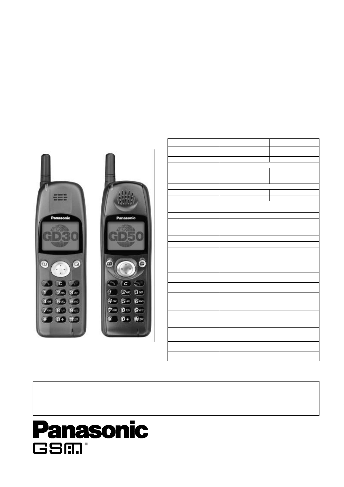
GD30/GD50 Personal Cellular Telephone
Frequency range Tx: 890 - 915 MHz
Tx/Rx frequency separation 45 MHz 95 MHz
RF channel bandwidth 200 kHz
Number of RF channels 124 374
Speech coding Full rate/Half rate/Enhanced
Operating temperature -10°C to +55°C
Type Class 4 Handheld Class 1 Handheld
RF Output Power 2 W maximum 1 W maximum
Modulation GMSK (BT = 0.3)
Connection 8 ch/TDMA
Voice digitizing 13 kbps RPE-LTP / 13 kps ACLEP / 5.6 kps CELP / VSLEP
Transmission speed 270.3 kbps
Diversity Frequency hopping
Signal Reception Double superheterodyne
Intermediate Frequencies 282 MHz and 45 MHz
Antenna Terminal Impedance50 Ω
Antenna VSWR <2.1 : 1
Dimensions Height: 135 mm
Volume 123 cc (150 cc with EB-BLD30 Battery)
Weight GD30: 130 g (170 g with EB-BLD30 Battery)
Display Graphical chip on glass liquid crystal, Alphanumeric,
Illumination 4 LEDs for the LCD (Green)
Keypad 17 keys, Navigation key
SIM Plug-in type only
External DC Supply Voltage3.6 V
Battery EB-BSD30: 3.6 V nominal, 670mAh, Ni-MH
Standby Battery Life
DRX 9
Conversation Battery Life
PL 7, DTX 50%
Rx: 935 - 960 MHz
Full rate
Width: 45 mm
Depth: 20.5 mm (30 mm with EB-BLD30 Battery)
GD50: 115 g (170 g with EB-BLD30 Battery)
16 x 3 characters, 5 icons and 6 x 1 characters
8 LEDs for the keypad (Green)
1 LED Incoming call (Green)
1 Charging LED (Red)
EB-BSD50: 3.6 V nominal, 670mAh, Li-Ion
EB-BLD30: 3.6V nominal, 1340mAh, Ni-MH
EB-BSD30/EB-BSD50: 95 hrs maximum
EB-BLD30: 190 hrs maximum
EB-BSD30/EB-BSD50: 180 minutes
EB-BLD30: 360 minutes
Order Number: MCUK991001C8
Handheld Portable
EB-GD30
EB-GD50
Specification
900 MHz 1800 MHz
Tx: 1710 - 1785 MHz
Rx: 1805 - 1880 MHz
Full rate/Half rate
Battery life figures are dependent on network conditi
WARNING
This service information is designed for experienced repair technicians only and is not designed for use by the general public. It does not contain warnings or
cautions to advise non-technical individuals of potential dangers in attempting to service a product.
Products powered by electricity should be serviced or repaired only by experienced professional technicians. Any attempt to ser
products dealt with in this service manual by anyone else could result in serious injury or death.
Issue 1
Revision 0
ice or repair the product or
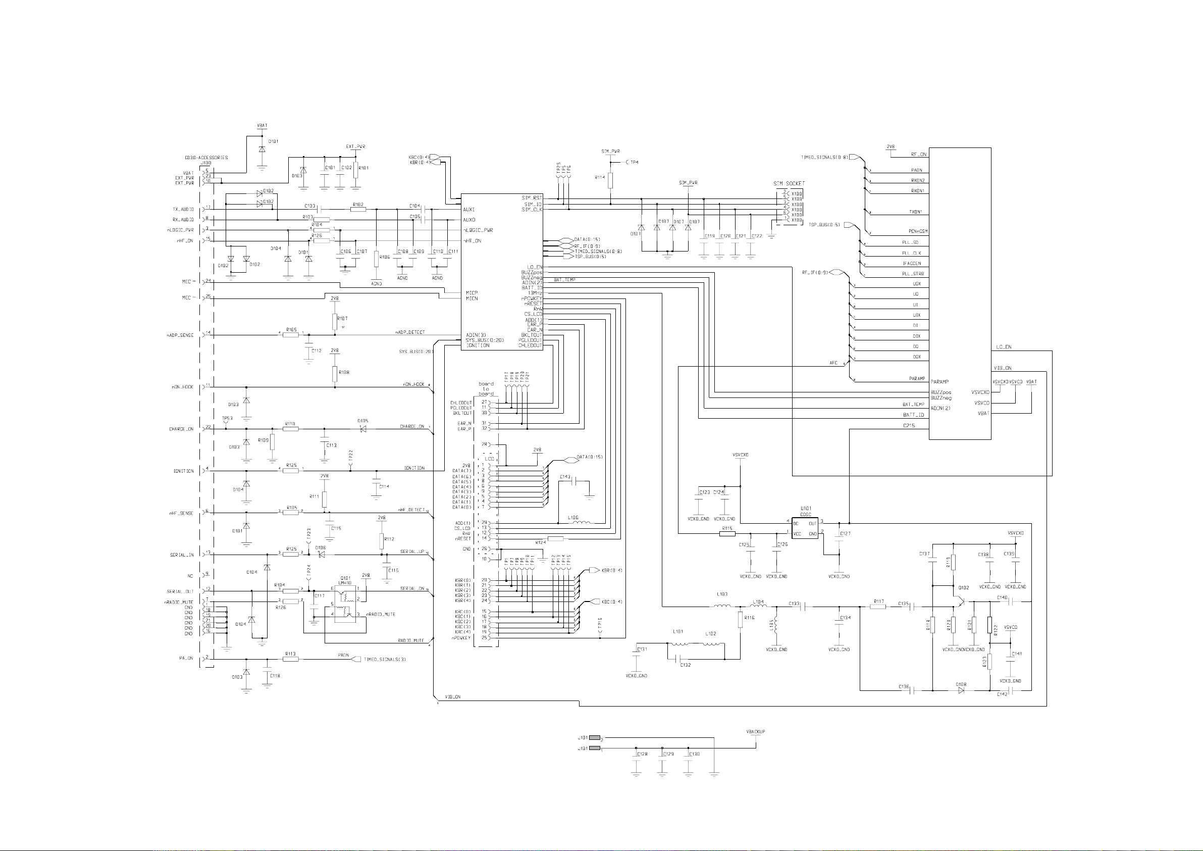
7 CIRCUIT DIAGRAMS
7.1 Main PCB: Top Level Diagram
CIRCUIT DIAGRAMS
BASEBAND
(Figure 7.2)
RF
(Figure 7.3)
10164-1
MCUK991001C8 Section 7 Issue 1
Service Manual – 55 – Revision 0
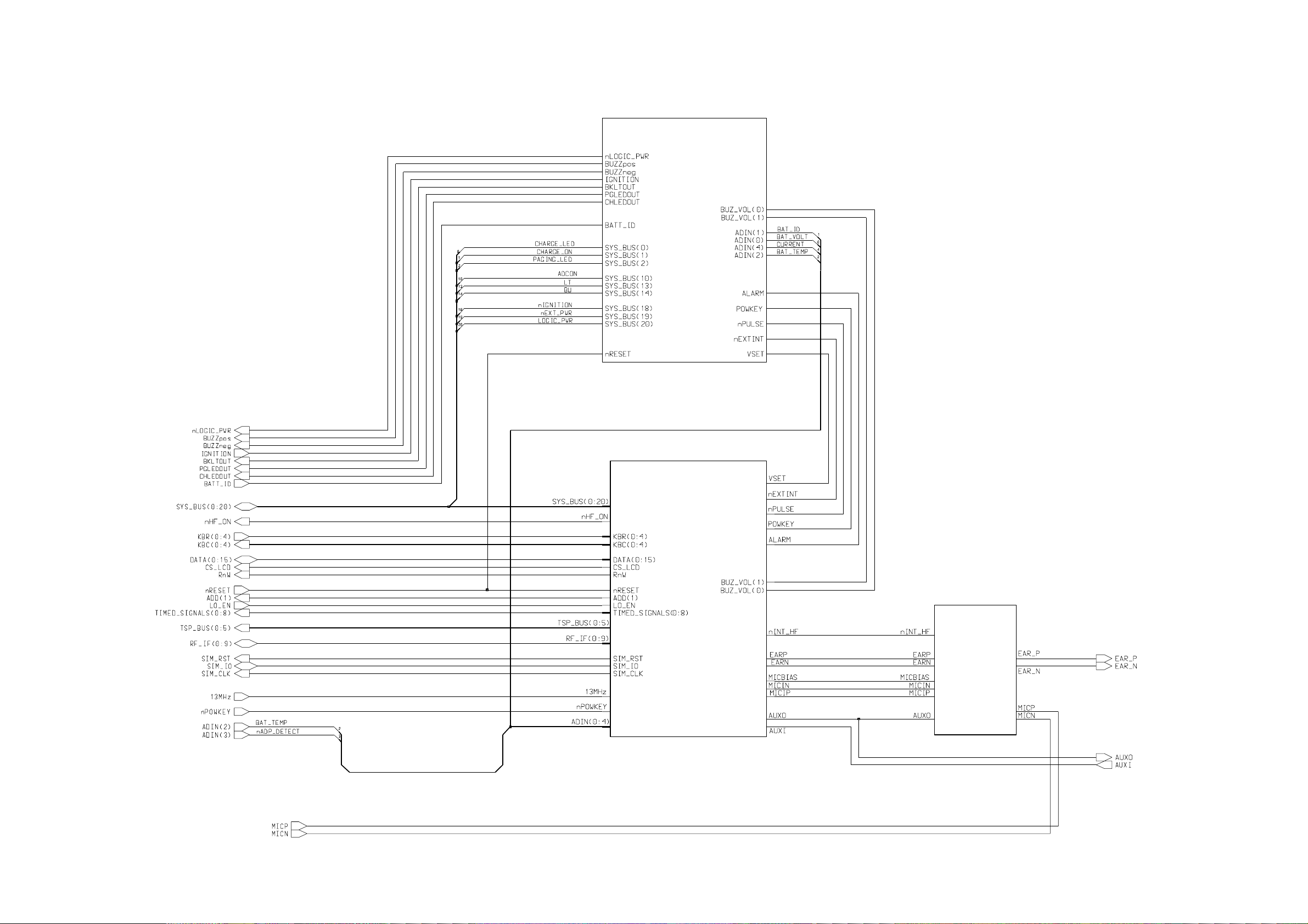
CIRCUIT DIAGRAMS
7.2 Main PCB: Baseband Overview
PSU
(Figure 7.4)
PROCESSOR
Figure 7.5
AUDIO
(Figure 7.6)
10165-1
Issue 1 Section 7 MCUK991001C8
Revision 0 – 56 – Service Manual
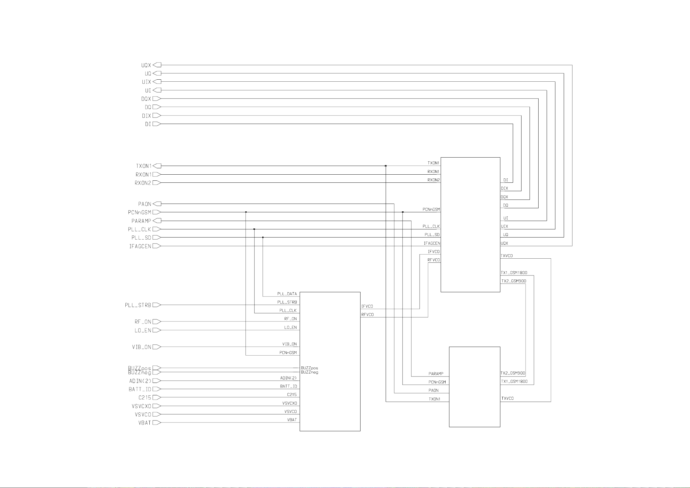
7.3 Main PCB: RF Overview
CIRCUIT DIAGRAMS
PSU &
SYNTHESIZER
(Figure 7.9)
RECEIVER &
Tx MODULATOR
(Figure 7.7)
TRANSMITTER
(Figure 7.8)
10166-1
MCUK991001C8 Section 7 Issue 1
Service Manual – 57 – Revision 0