

Panasonic FY-3009U1, FY-3012U1, FY-3015U1, FY-3509U1, FY-3512U1 Installation And Operating Instructions Manual
...
INSTALLATION AND
OPERATING INSTRUCTIONS
安裝使用說明書
Air Curtain
風幕機
Model No.
型號
FY-3009U1 FY-3012U1 FY-3015U1
FY-3509U1 FY-3512U1 FY-3515U1
FY-4009U1 FY-4012U1 FY-4015U1
Contents
Safety instructions ....................... 2
Installation cautions .................2~3
Supplied accessories .................... 4
Parts name and dimensions ......... 4
Requirement of installation .......... 5
How to install ..........................6~7
Multiple products operate
in group ....................................... 8
Wiring diagram ............................ 8
Operation methods ............... 8~9
Routine maintenance ........10~11
Trouble shooting........................ 12
Specifications ............................. 13
目錄
安全指示 ..................................... 14
安裝注意事項 .........................14~15
隨機提供的附件 ............................ 16
零部件名稱及尺寸 ......................... 16
安裝要求 ..................................... 17
安裝方法 ...............................18~19
多台組合運行 ............................... 20
接線示意圖 ............................. 20
使用方法 ........................20~21
維護保養 ...............................22~23
疑難排解 ..................................... 24
技術規格 ..................................... 25
Thank you for purchasing this Panasonic product.
Please read these installation and operating instructions carefully before attempting
to install, operate or service the Panasonic product. Please carefully read the
“Installation cautions” (P.2~3) of this installation and operating instructions before
installation. Failure to comply with installation and operating instructions could result
in personal injury or property damage. Please explain to users how to operate and
maintain the product after installation, and this booklet should be presented to users.
Please retain this booklet for future reference.
感謝您選購 Panasonic 產品。
安裝、使用或維修 Panasonic 產品前,請仔細閱讀本安裝使用說明書。請仔細閱讀本安裝
使用說明書的「安裝注意事項」(P.14
~
15) 再開始安裝。不按照安裝使用說明書操作可能會
導致受傷或財產損失。安裝後,請向用戶說明如何使用及維護本產品,並將本手冊交給用
戶。
請保管好本手冊以備日後參考。
■If the supply cord is damaged, it must be replaced by the manufacturer,
its service agent or similarly qualified persons in order to avoid a hazard.
■This product is not intended for use by persons (including children) with
reduced physical, sensory or mental capabilities, or lack of experience and
knowledge, unless they have been given supervision or instruction
concerning use of the product by a person responsible for their safety.
■Children should be supervised to ensure that they do not play with the
product.
■Make sure to disconnect the power supply before cleaning the product.
The following explanations must always be observed in order to prevent harm to
users or other people and prevent damage to property.
■The following displays are classified and explained to what extent harm or damage
occurs when the display details are ignored and the unit in question is wrongly used.
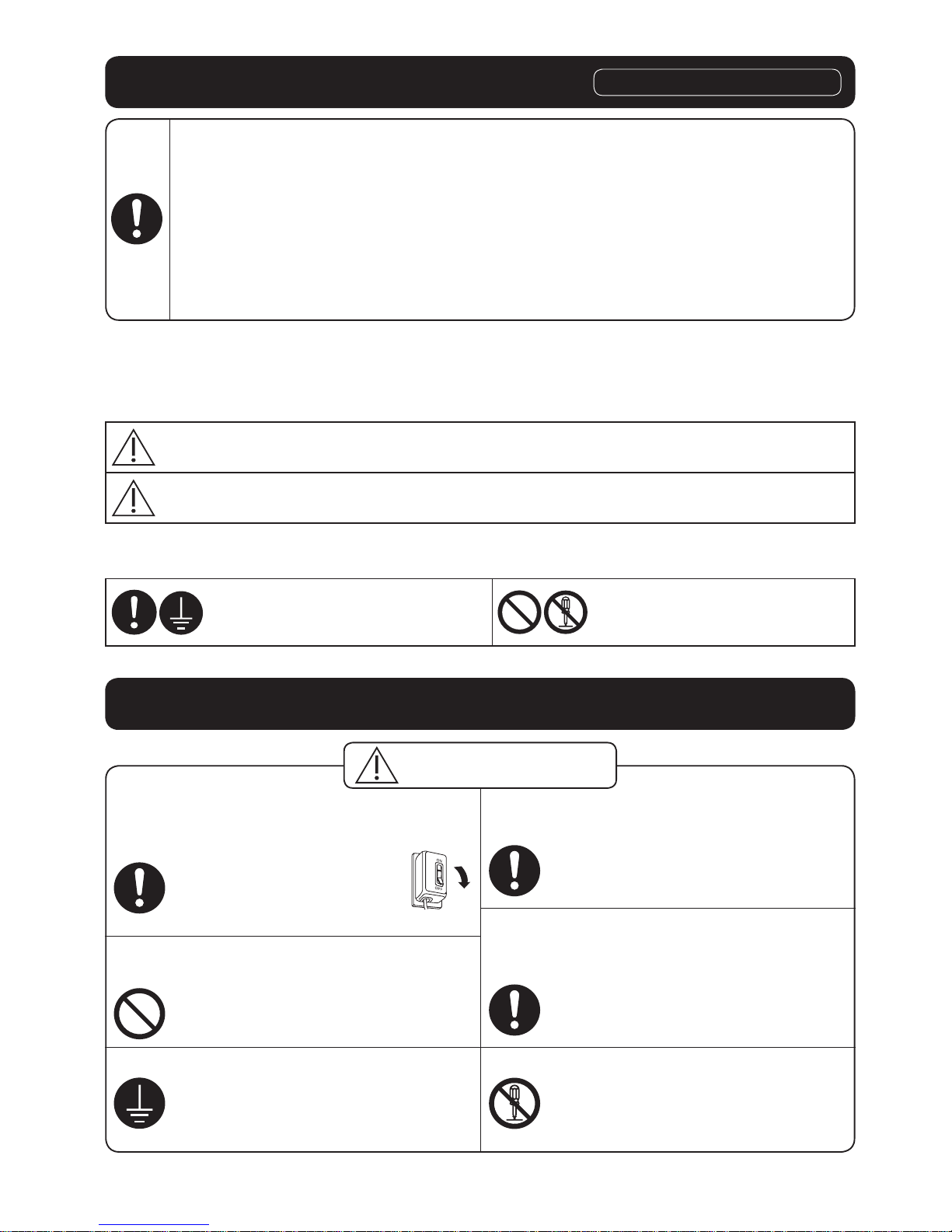
WARNING
This indication means: Must be treated seriously that
this may result in death or serious injury.
CAUTION
This indication means: Must be treated seriously that
this may result in injury or property damage.
■The types of details to be observed are classified and explained in the following
illustrated displays. (Below are the series of illustrated displays)
This symbol indicates the
“COMPULSORY” item that must
be followed without failure.
This symbol indicates the item
“PROHIBITED” to do.
Safety instructions
Please observe strictly
Installation cautions
■Please install an all-pole switch which
the contact separation is more than
3mm (Double pole switch).
Otherwise, it may cause
a short circuit, thus
resulting a fire.
■Do not operate the product other
than the rated voltage.
Otherwise, it may damage the
product or cause fire.
■The product must be grounded.
Otherwise, it may cause electric
shock when there is any trouble
or electric leakage.
■Wiring should be firmly connected
without any loose.
Otherwise, it may cause a short
circuit, thus resulting a fire.
■Installation should be done by
authorized person. The product
should be installed firmly.
Otherwise, the product may fall
down and it may cause injury.
■Do not reconstruct this product.
Otherwise, it may cause damage
to the product or injury.
WARNING
2
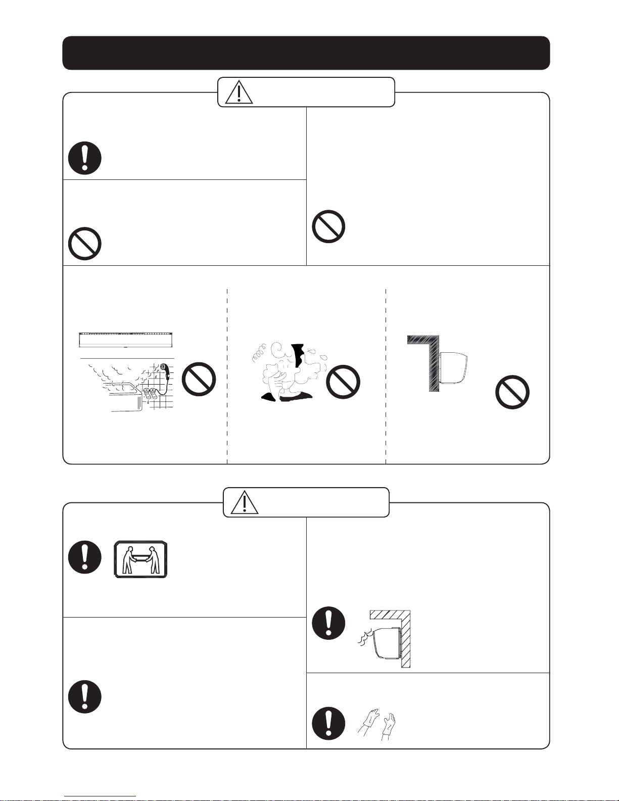
Installation cautions
■Product must be installed by 2 persons.
Otherwise, the product may fall
down and it may cause injury.
■The special-purpose or dedicated
parts, such as mounting fixtures,
must be used if such parts are
provided.
Otherwise, the product may
fall down and it may cause
injury.
■The product must be mounted on a
building which is strong enough. To
ensure it can bear over 5 times of
product weight. The building must be
reinforced if its strength can not be
ensured.
Otherwise, the product
may fall down and it
may cause injury.
■Please wear the gloves when installing
the product.
Otherwise, it may
cause damage.
CAUTION
■The product must be installed tightly.
Components must be installed tightly.
Otherwise, it may injury person
caused by product’s falling off.
■Do not install the product as the
method which is not approved in the
installation and operating instructions.
Otherwise, the product any fall
down and it may cause injury.
■It’s prohibited to install the product in
locations such as machinery, chemical
plants or research facilities where it
will be exposed to noxious gases
containing acids, alkali, organic
solvents, paint fumes, etc., to gases
contaning corrosive ingredients.
It could cause gas poisoning,
corrosion and degradation of
product that results in a fire.
WARNING
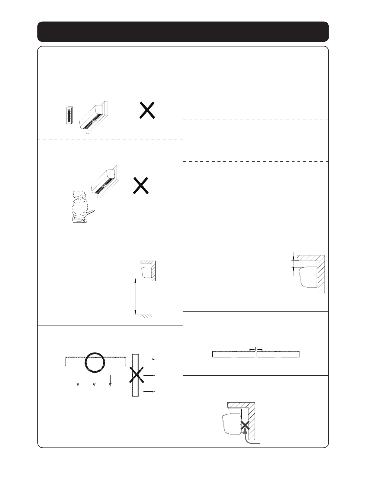
■It’s prohibited to install in the following locations.
Do not install the product
where there is steam.
Location with combustible
gas or emission of
exhaust gas.
Do not install the product
out of the window and
wall.
Indoor Outdoor
Otherwise, it may cause
a short circuit, thus
resulting in a fire.
Otherwise, it may cause
a short circuit, thus
resulting in a fire.
Otherwise, the product
may get wet in the rain
and cause a short circuit.
3
The following attachments are enclosed in the packing box of product. Be sure to
check if they are complete after unpacking, and if anything is missed, contact our
After-Sales Service Center or the dealer.
No. Drawing Name Quantity No. Drawing Name Quantity
1
Washer 6
4
Bolt M8×60L 6
2
Spring
washer
6
5
Installation and
operating
instructions
1
3
Nut
(M8)
6
6
Service
parts list
1
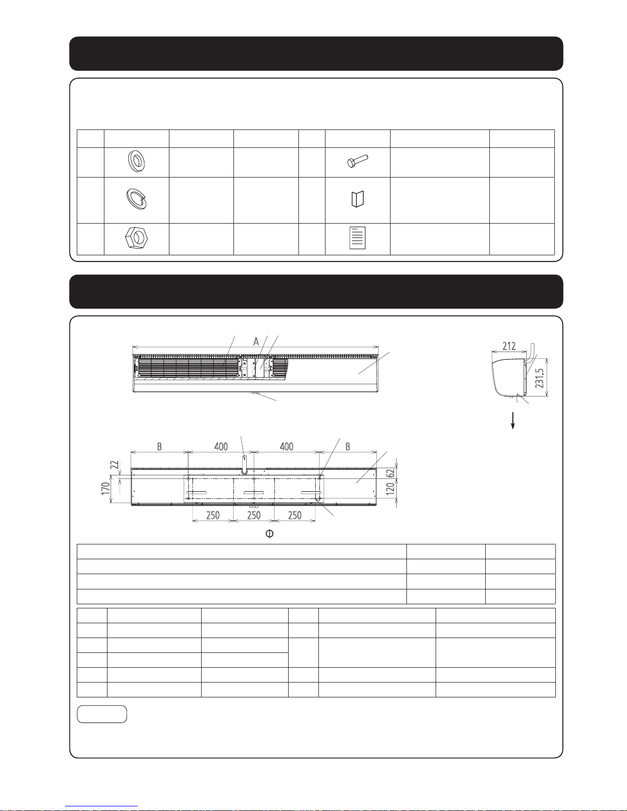
■Front view
A
■Back view
250 250 250
B 400
400
B
62120
22
170
Power supply cord
6 holes
(M8 bolts are used)
8 holes
(
8mm wooden screws are used)
■Right view
212
231.5
Direction
of
Air outlet
Model No. A B
FY-3009U1, FY-3509U1, FY-4009U1 900 50
FY-3012U1, FY-3512U1, FY-4012U1 1200 200
FY-3015U1, FY-3515U1, FY-4015U1 1500 350
No. Part name Classification No. Part name Classification
1
Front panel Resin ABS
6
Motor support Steel SGCC
2
Air outlet Resin ABS
7
Cross-flow impeller
Steel plate + ResinAS
+ Glass fiber
3
Mounting plate Steel SGCC
4
Back panel Steel SGCC
8
Push–button switch Assembly part
5
Motor Assembly part
9
Guide plate Resin ABS
Notice
Please refer to the table above to recycle the materials as much as possible when
discarding this product.
Parts name and dimensions
Supplied accessories
4
Requirement of installation
The applicable ambient temperature
of this product is in the range of
-10°C~40°C.
đ
Do not install the product where it is
exposed to oil fumes.
It’s prohibited to install in the uneven
surface. (Flatness shall be 3mm below.)
Distortion results in reducing the
separation performance.
Locations where freezing could happen.
Otherwise, it may damage the
product or cause fire.
Do not install the product in the place
with many dust.
Impeller deformation may be
caused by sand and dust piling
up, which may affect the
performance.
■Please observe the following requirement. Otherwise, it may cause the product
aging and breakdown.
■The lowest surface of this product
should be installed above 2.3m from
the floor after installation.
Avoiding any accident.
■Please install the product horizontally,
don’t vertically install the product.
It could affect the
performance of bearing.
■The distance between product and
ceiling must be 50mm above.
The ceiling is excessively
close to air inlet that may
reduce the separation
performance.
■Ensure the space among products is
20~40mm when multiple products
operate in row.
20~40mm
Easy for installation.
■Please block the clearance between
wall and product.
Prevent product
from sucking in
outdoor air from
clearances.
2.3m above
50mm above
5
How to install
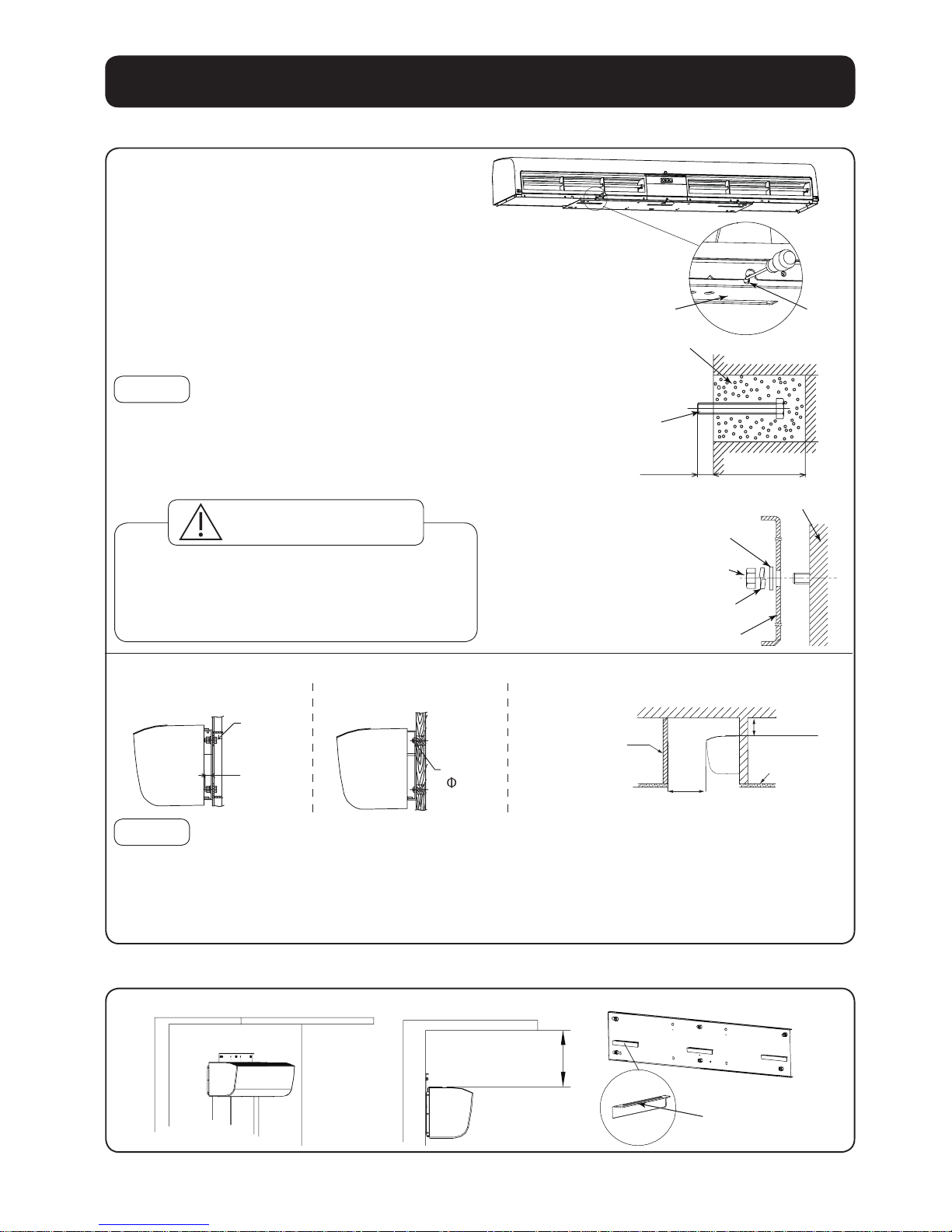
1. Fix the mounting plate
■Mounting on concrete wall.
1. Remove mounting plate from product.
Taking the mounting plate by removing the
3 screws.
2. Firmly fix the bolts in the proper position.
· Determine the position on the wall and drill
into the wall.
· Fit the bolts into the holes.
· Fill the holes with concrete.
· Install the mounting plate and check if it’s
secured when the concrete solidifies.
Notice
Distance of bolt head away from wall should
be 13~15mm.
3. Fix the mounting plate with washers, spring
washers and nuts.
2.Preparation before wiring
Carry out this step if the distance between top
(
face of product and ceiling is less than 150mm.
)
Pre-hang up the product into the bottom holes of mounting plate.
150mm above
Bottom holes
Mounting
Plate
Screw
Concrete
Bolt
M8×60L
13-15mm
About 70mm
Diameter: 40-50mm
Washer
Wall
Nut
Spring washer
Mounting plate
■Please use the mounting plate
provided with product to avoid the
dropping caused by insufficient
strength.
CAUTION
■Other installation methods
M8 bolt
15mm
below
100mm above
Partition plate
(not supply) is
installed at four
sides.
Ceiling
350mm above
Wooden
screw
( 8×60L)
Mounting on steel
hanger
Notice
1. It’s prohibited to install the product on hollow
wall, otherwise it may produce noises.
2. Conduct the necessary reinforcement,
depending on the particular condition to
avoid noise resonance and vibration.
1. The inside space of ceiling should exceeding
the dimensions as indicated above to ensure
the space of air inlet, please select the larger
model if space of air inlet can’t be reserved.
2. Don’t place the substances near the air inlet
or outlet grille (include the grille).
It could affect the performance.
Mounting on wooden
frame
Mounting inside the ceiling
6
How to install
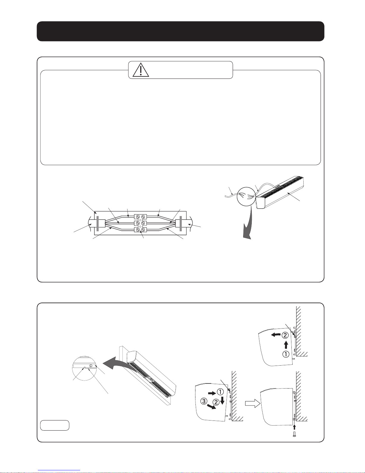
3. Wiring
■Wiring is required to follow the local wiring regulations.
Otherwise, it may cause fire.
■Please select 60227 IEC 53 ordinary polyvinyl chloride sheathed cord.
Nominal cross-sectional area of conductors is 3×1.0mm2.
Otherwise, it may cause fire.
■The product is not provided with Double pole switch and leakage protection
switch. Please purchase them in market.
■It is required to use terminal (not supply) that complies IEC 60998 and wiring
box (not supply) that complies local regulation.
■Wiring should be firmly connected without any loose.
WARNING
Wiring box
(not supply)
Neutral
(N)
Live
(L)
Brown
(L)
Blue
(N)
Power cord
of the product
Green/Yellow
(Earth)
Terminal block
(not supply)
Earth wire
Power
supply cord
Lead wire
from source
Air curtain
Power cord
of the product
■ Connect the power cord (included earth) of product to lead wire in accordance with the wiring
diagram.
■ Make sure all connections are fastened firmly after finishing wiring.
4. Installation of product
1. Remove the product from the bottom holes.
2. Fixing the product.
Align the groove of back panel with both sides of
mounting plate. Fit the hooks into the top holes
of mounting plate.
Groove
Mounting plate
Back panel
3. Fasten the screws. (3 places)
Notice
The torque is suggested to be 1.2N·m.
Bottom holes
Top holes
7
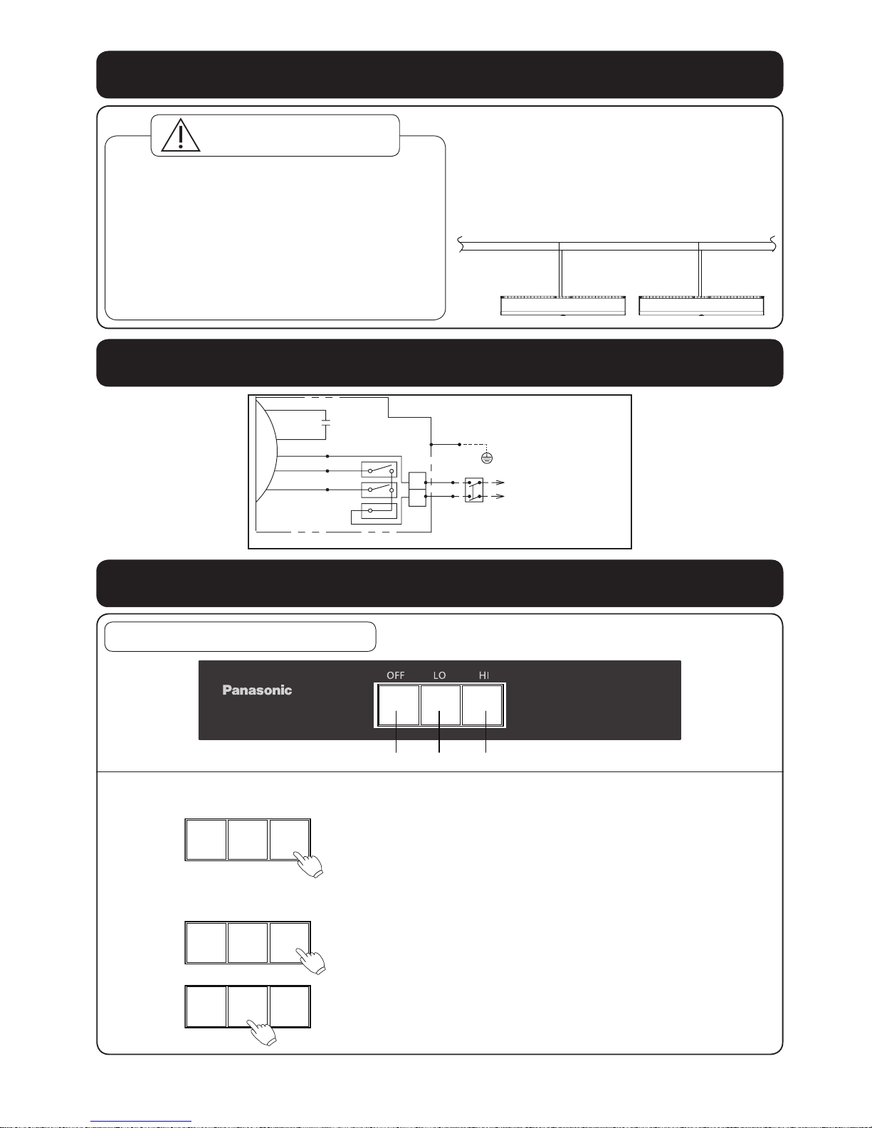
Multiple products operate in group
●Please purchase necessary parts
following with local electrical
requirements, except the power
supply cord.
Power supply cord
■Please select the switch of whose
capacity has 1.2~1.5 times total current,
when multiple products operate.
■Earth leakage breaker protector
should be equipped, otherwise it may
cause an electrical shock.
■The number of interlocking operation
is not more than 6.
WARNING
Wiring diagram
N
L
N
L
Motor
TERMINAL
Power
Source
Red
Orange
Black Black
Green/Yellow
Blue
Brown
Double Pole Switch
Customer Provide
(Contact Point Separate Distance Over 3mm)
Switch
White
White(H)
Yellow(L) Yellow
Operation of Control panel
/2:+,*+
FY-4009U1
OFF LOW HIGH
Operation methods
※Representative model
1
Start to operate
2)) /2 +,
2
Select the mode of operation
/2 +,2))
/2 +,2))
Press “HI” or “LO” button to start the product as
shown in left figure.
Press “HI” button if high air velocity is required.
Press “LO” button if quiet and low velocity is
required.
Capacitor
8
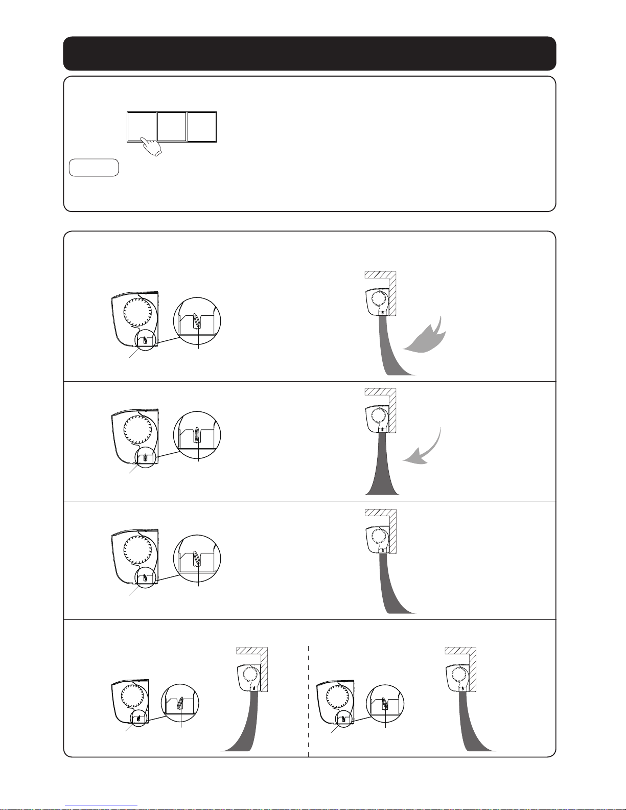
■Guide vane in air outlet can be adjusted according to service environment to
reach the ideal separation performance.
1
While strong wind in outdoor
Air outlet
Guide vane
Strong wind
in outdoor
2
While light wind in outdoor
Air outlet
Guide vane
Light wind
in outdoor
3
Heating
Air outlet
Guide vane
Hot indoor Cold outdoor
4
Cooling
1. Room has opening
(window, grille, etc.)
Air outlet
Guide vane
Cold
indoor
Hot
outdoor
Air outlet
Guide vane
Cold
indoor
Hot
outdoor
Operation methods
3
Stop operating
/2 +,2))
Notice
The product is in stand-by mode after pressing the “OFF”, it’s still connected to the
power.
Press “OFF” button to stop the product.
2. Room is air tight
(no opening)
9
 Loading...