

Panasonic FX-411, FX-411B, FX-411-C2, FX-411G, FX-411B-C2 Instruction Manual
...
MJE-FX411 No.0034-50V
SPECIFICATIONS
Display
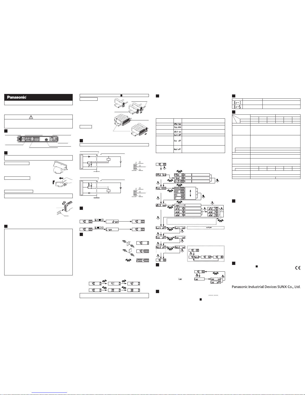
Communication error has occurred at time of connection.
The load has short-circuited
and excess current is flowing.
Error description Measures
Turn off the power, then check the load.
Check if the mounted amplifiers are in close contact
with each other.
ERROR DISPLAY INDICATOR READINGS
10
٨ Mode table
Notes: 1) This mode is not incorporated in the blue LED type and green LED type.
2) While the peak / bottom hold mode is ON, the digital display is not turned off even if the
Eco mode is set to ON.
The light emitting intensity can be switched among four levels.
Timer settings can be select ed; Without timer / OFF-delay timer /
ON-delay timer / ONE-SHOT timer. Also the timer period can be set.
Emitting intensity selection mode (Note 1)
Timer setting mode
The display on the digital display can be inverted.
Digital display inversion mode
If no key is pressed for approximately 20 sec. while in 'RUN' mode, the
digital display turns off automatically. Press the setting switch or move
the operation selection switch to make the display light up again. The
digital display will light up when the threshold value adjuster is turned,
but note that this will also cause the threshold value to change.
Eco mode (Note 2)
If the setting switch is pressed while 'RUN' mode is active, the display
will alternate between the peak hold value and the bottom hold value.
(The display will refresh every 2 sec.) The display will return to normal if any operation other than threshold value setting is carried out.
Peak / Bottom hold mode
Response time change mode
The response time can be set.
Mode Description
Factory
setting
MODE SELECTION
7
٨
٨
٨
٨
٨
When the setting switch is pressed and held for 2 sec. or more, 'SET' mode (mode
setting screen) is activated.
If the setting switch is pressed while in 'SET' mode, the mode will change.
If the threshold value adjuster is turned while a mode is active, the setting item will change and blink.
When the setting switch is pressed at the item you would like to set, it blinks 3
times and then the setting is confirmed and the mode switches to the next mode.
If the setting switch is pressed and held for 2 sec. or more or do not press any key for
15 sec. while 'SET' mode is active, the mode will switch automatically to 'RUN'mode.
11
٨٨Never use this product as a sensing device for personnel protection.
In case of using sensing devices for personnel protection, use products which
meet laws and standards, such as OSHA, ANSI or IEC etc., for personnel protection applicable in each region or country.
WARNING
PART DESCRIPTION
1
Operation indicator (Orange)
Digital display (Green)
Threshold value (RUN condition)
Stability indicator (Green)
Threshold value adjuster (Note)
Operation selection switch
Setting switch
Incident light intensity (RUN condition)
Digital display (Red)
CASCADING
3
٨
٨
٨
٨
٨
٨
٨
٨
٨
Make sure that the power supply is off while adding or removing the amplifiers.
Make sure to check the allowable ambient temperature, as it depends on the
number of amplifiers connected in cascade.
In case two, or more, amplifiers are connected in cascade, make sure to mount
them on a DIN rail.
When the amplifiers move on the DIN rail depending on the attaching condition
or the amplifiers are mounted close to each other in cascade, fit them between
the optional end plates (MS-DIN-E) mounted at the two ends.
Up to maximum 15 amplifiers can be added (total 16 amplifiers connected in cascade.)
When connecting more than two amplifiers in cascade, use the sub cable
(CN-71-Cغ) as the quick-connection cable for the second amplifier onwards.
When connecting amplifiers not close to each other in parallel, be sure to mount
the optional end plate (MS-DIN-E) at both sides of each amplifier or affix the
communication window seal of the optional amplifier protection seal (FX-MB1) to
the communication windows. For details, refer to the instruction manual enclosed
with the FX-MB1.
When the connector type and the cable type or different LED (red / blue / green)
types are connected in cascade, mount the identical models together.
When this product is used with the other digital fiber amplifiers, be sure to place
this product to the left most position (When you look from the connector side). If
this product is not placed to the leftmost position, this product may not operate
properly.
Make sure that the power supply is off while connecting disconnecting the amplifiers and the quick-connection cables.
MOUNTING
2
Ԙ
35mm width DIN rail
ԙ
Ԙ
ԙ
ԘԙFit the rear part of the mounting section of the amplifier
on a DIN rail.
Press down the rear part of the mounting section of the
unit on the DIN rail and fit the front part of the mounting
section to the DIN rail.
How to mount the amplifier
ԘԙPush the amplifier forward.
Lift up the front part of the amplifier to remove it.
Take care that if the front part is lifted without pushing the
amplifier forward, the hook on the rear portion of the mounting section is likely to break.
Note:
How to remove the amplifier
ԙ
Ԙ
Fiber
lock lever
Fiber
Ԛ
How to connect the fiber cables
Ԙ
ԙ
Ԛ
Snap the fiber lock lever down.
Insert the fiber cables slowly into the inlets until they
stop. (Note 1)
Return the fiber lock lever to the original position, till it
stops.
Notes: 1)2)In case the fiber cables are not inserted to a position where
they stop, the sensing range reduces. In case of a flexible
fiber, take care that it may bend inside the amplifier, during
insertion.
With the coaxial reflective type fiber, such as, FD-G4 or FD-FM2, insert the single-core fiber cable into the beam-emitting inlet and the multi-core fiber cable into the beam-receiving inlet. If they are inserted in reverse, the sensing accuracy will deteriorate.
Be sure to fit the attachment to the fibers first before inserting the fibers to the
amplifier. For details, refer to the instruction manual enclosed with the fibers.
Make sure that the power supply is off while wiring.
I/O CIRCUIT DIAGRAMS
4
Notes: 1)2)The quick-connection sub cable does not have +V (brown) and 0V (blue).
The power is supplied from the connector of the main cable.
50mA max., if five, or more, the connector type amplifiers are connected in cascade.
٨ NPN output type
1
+V
3
Output
2
0V
Terminal arrangement diagram of the
connector type
1
2
3
100mA max.
(Note 2)
Load
(Brown) +V (Note 1)
(Black) Output
+
12 to 24V DC
r10%
-
(Blue) 0V (Note 1)
Users' circuitInternal circuit
Sensor circuit
Terminal No. of connector type
Cable type / Color code of quickconnection cable
٨ PNP output type
1
+V
3
Output
2
0V
Terminal arrangement diagram of the
connector type
1
2
3
Load
+
12 to 24V DC
r10%
-
100mA max.
(Note 2)
(Brown) +V (Note 1)
(Black) Output
(Blue) 0V (Note 1)
Users' circuitInternal circuit
Sensor circuit
Terminal No. of connector type
Cable type / Color code of quickconnection cable
SWITCHING OUTPUT OPERATION
5
٨
The operation selection switch can be used to display different output operations
(L-ON / D-ON) on the digital display.
<When set to Light-ON (L-ON)>
<When set to Dark-ON (D-ON)>
Disappears automatically
after 2 seconds.
Disappears automatically
after 2 seconds.
THRESHOLD VALUE (SENSITIVITY) ADJUSTMENT
6
Ԙ Check the incident light intensity [in the digital
display (red)] when a sensing object is placed
in the sensing position.
ԙ Check the incident light intensity [in the digital
display (red)] when the sensing object is
removed from the sensing position.
Ԛ Turn the threshold value adjuster to the
threshold value [in the digital display (green)]
that is the value in between Ԙ and ԙ. (The
threshold value is automatically written to the
EEPROM.)
(Incident light intensity)
(Incident light intensity)
(Threshold value)
Sensing
object
٨
When the threshold value adjuster is turned clockwise, the threshold value
increases. When the threshold value adjuster is turned counterclockwise, the
threshold value decreases.
<Threshold value setting method>
If there is a sufficient level of margin in the incident light intensity, the stability indicator (green) will light up.
(Threshold value)
(Threshold value)
Notes: 1)
2)
3)
4)
FX-412غ, with the sensitivity adjuster shaped so that it can be turned manually using
fingers, is also available. However, the cable type is not available for FX-412غ.
50mA, the connector type five, or more, amplifiers are connected in cascade.
When the power supply is switched on, the light emission timing is automatically set for
interference prevention.
The cable for amplifier connection is not supplied as an accessory. Make sure to use the
optional quick-connection cables given below.
Main cable (3-core): CN-73-C1 (cable length 1m), CN-73-C2 (cable length 2m)
CN-73-C5 (cable length 5m)
Sub cable (1-core) : CN-71-C1 (cable length 1m), CN-71-C2 (cable length 2m)
CN-71-C5 (cable length 5m)
CAUTIONS
٨
٨
٨
٨
٨
٨
٨
٨
٨
٨
٨
٨
٨
٨
٨
٨
٨
٨
This product has been developed / produced for industrial use only.
Take care that wrong wiring will damage the sensor.
Make sure that the power supply is off while wiring.
Verify that the supply voltage variation is within the rating.
Take care that if a voltage exceeding the rated range is applied, or if an AC
power supply is directly connected, the sensor may get burnt or damaged.
In case noise generating equipment (switching regulator, inverter motor, etc.) is
used in the vicinity of this product, connect the frame ground (F.G.) terminal of
the equipment to an actual ground.
If power is supplied from a commercial switching regulator, ensure that the frame
ground (F.G.) terminal of the power supply is connected to an actual ground.
Do not use during the initial transient time (0.5 sec.) after the power supply is
switched on.
Take care that short-circuit of the load or wrong wiring may burn or damage the sensor.
Do not run the wires together with high-voltage lines or power lines or put them in
the same raceway. This can cause malfunction due to induction.
Extension up to total 100m (if 5 to 8 units are connected in cascade: 50m, if 9 to
16 units are connected in cascade: 20m) is possible with 0.3mm2, or more, cable.
However, in order to reduce noise, make the wiring as short as possible.
Take care that cable extension increases the residual voltage.
This sensor is suitable for indoor use only.
Avoid dust, dirt, and steam.
Take care that the product does not come in contact with water, oil, grease,
organic solvents, such as, thinner, etc., strong acid or alkaline.
This sensor cannot be used in an environment containing inflammable or explosive gases.
Never disassemble or modify the sensor.
The changes to the settings are written to the EEPROM, but because the
EEPROM has a limited service life, you should avoid changing the settings any
more than 1 million times.
12
<RUN condition>
<RUN condition>
<SET condition>
(
Response time
change mode
)
Standard
Response time: 500Ǵs or less
Response time: 4.5ms or less
Long-range
Response time: 150Ǵs or less
High speed
(
Emitting intensity
selection mode
)
(Note 1)
Emitting power Hi
Emitting power Lo
(
Timer setting
mode
)
Without timer
OFF-delay
ON-delay
ONE-SHOT
The timer period can be set within the following ranges:
1 to 10 ms: 1 ms units; 10 to 100 ms: 10 ms units; 100 to 500 ms: 50 ms units
500 to 1000 ms: 100 ms units; 1000 to 3000 ms: 500 ms units
Press and hold for 2 seconds or more
(
Digital display
inversion mode
)
(Eco mode)
Peak / Bottom
hold mode
(The actual display will be ' '.)
<RUN condition>
(Peak value)
(Bottom value)
Note:
This mode is not incorporated
in the blue LED type and
green LED type.
9
When the setting switch is pressed and held for 10 sec., until ' ' is displayed while in 'RUN' mode, the all settings are returned to the factory setting.
(For the factory setting, refer to '٨Mode table'in ' MODE SELECTION'.)
7
FACTORY SETTING
٨
KEY LOCK FUNCTION
8
Note:
Although the display changes to the indication of 'SET'
condition 2 sec. after pressing the setting switch, keep
pressing the switch. Furthermore, the sensor does not go into the key lock setting from 'SET' condition.
<RUN condition>
Press and hold
for 5 sec. (Note)
(Set to OFF)
(Set to ON)
٨٨When the setting switch is pressed and
hold for 5 sec. while in 'RUN' mode, the
key lock function can be set / canceled.
When the key lock function is set to ON,
even if the threshold value adjuster or the
setting switch is operated, ' ' is displayed
and the key operation cannot be carried out.
For mounting and removing the amplifier, refer to ' MOUNTING'.
2
Ԙ
ԙ
Ԛ
ԛ
Mount the amplifiers, one by one,
on the DIN rail.
Slide the amplifiers next to each
other, and connect the quick-connection cables.
Mount the optional end plates
(MS-DIN-E) at both the ends to
hold the amplifiers between their
flat sides.
Tighten the screws to fix the end
plates.
Ԙ
ԙ
Ԛ
Loosen the screws of the end plates.
Remove the end plates.
Slide the amplifiers and remove
them one by one.
Cascading method
Dismantling
Main cable (CN-73-Cغ)
(optional)
End plates (MS-DIN-E)
(optional)
End plates (MS-DIN-E)
(optional)
Sub cable (CN-71-Cغ)
(optional)
Slide
Slide
FX-411GP-C2
FX-411P-C2
PNP output
NPN output (Note 1)
FX-411BP-C2
FX-411P
FX-411BP
FX-411GP
FX-411 FX-411B FX-411G
FX-411B-C2
FX-411-C2
FX-411G-C2
Item
Type
Red LED Blue LED
Green LED
Red LED Blue LED
Green LED
Connector type Cable type
FAST: 150Ǵs or less, STD: 500Ǵs or less, U-LG: 4.5ms or less selectable with switch
Light-ON or Dark-ON, selectable with switchOutput operation
Incorporated
Short-circuit protection
<Red LED type>
Normal operation: 960mW or less
(Current consumption 40mA or less at 24V supply voltage)
ECO mode: 840mW or less
(Current consumption 35mA or less at 24V supply voltage)
<Blue LED type / Green LED type>
Normal operation: 720mW or less
(Current consumption 30mA or less at 24V supply voltage)
ECO mode: 580mW or less
(Current consumption 24mA or less at 24V supply voltage)
Response time
Output
<NPN output type>
NPN open-collector transistor
Maximum sink current: 100mA (Note 2)
Applied voltage: 30V DC or less
(between output and 0V)
Residual voltage: 1.5V or less
[at 100mA (Note 2) sink current]
<PNP output type>
PNP open-collector transistor
Maximum source current: 100mA (Note 2)
Applied voltage: 30V DC or less
(between output and +V)
Residual voltage: 1.5V or less
[at 100mA (Note 2) source current]
Power consumption
12 to 24V DCr10% Ripple P-P 10% or lessSupply voltage
Incorporated [up to four fibers can be mounted adjacently (However,
U-LG mode is eight fibers)
Interference prevention
function
Cable
35 to 85% RH, Storage: 35 to 85% RH
Ambient temperature
-10 to +55 (If 4 to 7 units are connected in cascade: -10 to +50,
if 8 to 16 units are connected in cascade: -10 to +45)
(No dew condensation or icing allowed), Storage: -20 to +70
Peak emission wavelength
650nm 470nm 525nm 650nm 470nm 525nm
Emitting element
Ambient humidity
0.3mm
2
3-core cabtyre cable, 2m long (Cable type only)
20g approx. 60g approx.
Enclosure: Heat-resistant ABS, Transparent cover: Polycarbonate
Setting switch: Heat-resistant ABS, Threshold value adjuster: Polycarbonate
Material
Weight
Green LED
Red LED Blue LED
Green LED
Red LED Blue LED
Model
No.
Thank you very much for purchasing Panasonic products. Please read this Instruction
Manual carefully and thoroughly for the correct and optimum use of this product.
Kindly keep this manual in a convenient place for quick reference.
INSTRUCTION MANUAL
Digital Fiber Sensor Amplifier FX-400 Series
٨
٨
The models listed under “ SPECIFICATIONS” come with CE Marking.
As for all other models, please contact our office.
Contact for CE
<Until June 30 ,2013>
Panasonic Electric Works Europe AG
Rudolf-Diesel-Ring 2, D-83607 Holzkirchen, Germany
<From July 1 ,2013>
Panasonic Marketing Europe GmbH Panasonic Testing Center
Winsbergring 15, 22525 Hamburg,Germany
11
INTENDED PRODUCTS FOR CE MARKING
13
Phone: 800.894.0412 - Fax: 888.723.4773 - Web: www.clrwtr.com - Email: info@clrwtr.com
 Loading...