

Panasonic FX-311P, FX-311BP, FX-311GP, FX-311, FX-311B Instruction Manual
...
CAUTIONS
2
●
●
●
●
●
●
●
●
●
●
●
●
●
●
●
This product has been developed / produced for industrial use only.
Make sure that the power supply is off while wiring.
Verify that the supply voltage variation is within the rating.
Take care that if a voltage exceeding the rated range is applied, or if an AC power
supply is directly connected, the sensor may get burnt or damaged.
In case noise generating equipment (switching regulator, inverter motor, etc.) is
used in the vicinity of this product, connect the frame ground (F.G.) terminal of the
equipment to an actual ground.
If power is supplied from a commercial switching regulator, ensure that the frame
ground (F.G.) terminal of the power supply is connected to an actual ground.
Do not use during the initial transient time (0.5 sec.) after the power supply is
switched on.
Take care that short-circuit of the load or wrong wiring may burn or damage the
sensor.
Do not run the wires together with high-voltage lines or power lines or put them in
the same raceway. This can cause malfunction due to induction.
Make sure to use the optional quick-connection cable for the connection of the
amplifier. Extension up to total 100m is possible with 0.3mm
2
, or more, cable.
However, in order to reduce noise, make the wiring as short as possible.
This sensor is suitable for indoor use only.
Avoid dust, dirt, and steam.
Take care that the sensor does not come in contact with water, oil, grease, organic
solvents, such as, thinner etc., or strong acid, and alkaline.
This sensor cannot be used in an environment containing inflammable or
explosive gases.
Never disassemble or modify the sensor.
●●Never use this product as a sensing device for personnel
protection.
In case of using sensing devices for personnel protection,
use
products which meet
standards, such as OSHA
, ANSI or IEC
etc.
, for personnel protection applicable in each region or
country.
WARNING
SPECIFICATIONS
1
840mW or less (current consumption 35mA or less at 24V supply voltage)
Power consumption
12 to 24V DC±10% Ripple P-P 10% or lessSupply voltage
Blue LED type Green LED typeType Red LED type
PNP output
FX-311BP FX-311GPFX-311P
FX-311B FX-311G
NPN output
Model
No.
FX-311
Item
Output
Selectable: 250μs or
less (for S-D, STD),
2ms or less (for LONG)
Green LED (lights up under stable light-received condition or stable
dark condition)
Stability indicator
Selectable: 150μs or less (for FAST),
250μs or less (for STD), 2ms or less
(for LONG)
Response time
Orange LED (lights up when the output is ON)Operation indicator
Incorporated
Short-circuit protection
Selectable either Light-ON or Dark-ONOutput operation
Timer function
Incorporated with OFF-delay timer, selectable either effective
(approx. 10ms or 40ms) or ineffective
12-turn potentiometer with indicator (Pointer part: red backlight) (Note 2)
Sensitivity adjuster
Incorporated (up to four fibers can be mounted adjacently)
Interference prevention
function
-10 to +55℃ (If 4 to 7 units are connected in cascade: -10 to +50℃,
if 8 to 16 units are connected in cascade: -10 to +45℃)
(No dew condensation or icing allowed), Storage: -20 to +70℃
Ambient temperature
Green LED (modulated)
Red LED (modulated) Blue LED (modulated)
Enclosure: Heat-resistant ABS, Transparent cover: Polycarbonate
Material
15g approx.Weight
35 to 85% RH, Storage: 35 to 85% RHAmbient humidity
Emitting element
<NPN output type>
NPN open-collector transistor
・
Maximum sink current: 100mA (Note 1)
・Applied voltage: 30V DC or less
(between output and 0V)
・Residual voltage: 1.5V or less
[at 100mA (Note 1) sink current]
<PNP output type>
PNP open-collector transistor
・
Maximum source current: 100mA (Note 1)
・Applied voltage: 30V DC or less
(between output and +V)
・Residual voltage: 1.5V or less
[at 100mA (Note 1) source current]
Notes: 1)
2)
3)
50mA if five, or more, amplifiers are connected together.
The red backlight of the pointer part lights up when the power is turned ON and when the
sensitivity is adjusted.
The cable for amplifier connection is not supplied as an accessory. Make sure to use the
optional quick-connection cables given below.
Main cable (3-core): CN-73-C1 (cable length 1m), CN-73-C2 (cable length 2m)
CN-73-C5 (cable length 5m)
Sub cable (1-core):
CN-71-C1 (cable length 1m), CN-71-C2 (cable length 2m)
CN-71-C5 (cable length 5m)
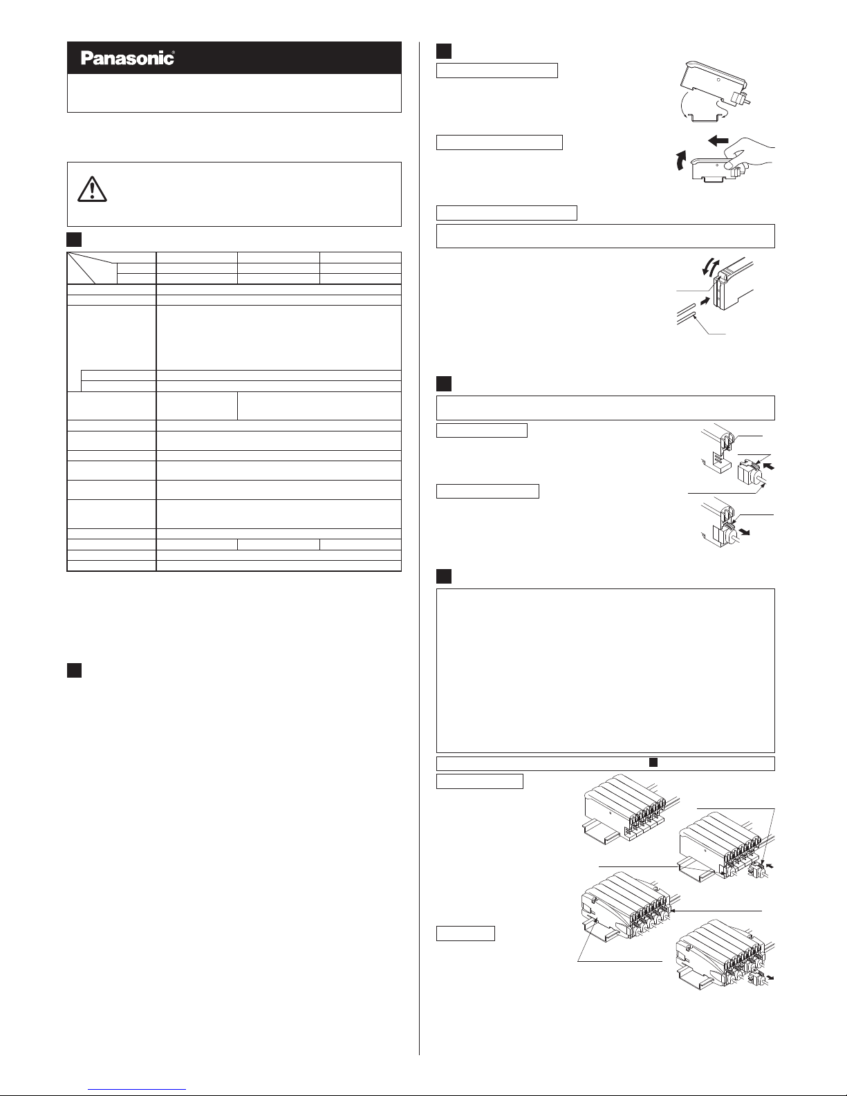
MOUNTING
3
①②Fit the rear part of the mounting section of the amplifier
on a 35mm width DIN rail.
Press down the rear part of the mounting section of the
unit on the 35mm width DIN rail and fit the front part of
the mounting section to the DIN rail.
How to mount the amplifier
①
35mm width DIN rail
②
①②Push the amplifier forward.
Lift up the front part of the amplifier to remove it.
①
②
Take care that if the front part is lifted without pushing the
amplifier forward, the hook on the rear portion of the mounting
section is likely to break.
Note:
How to remove the amplifier
How to connect the fiber cables
①
②
③
Snap the fiber lock lever down.
Insert the fiber cables slowly into the inlets until they
stop. (Note 1)
Return the fiber lock lever to the original position, till it
stops.
Notes: 1)
2)
In case the fiber cables are not inserted to a position where
they stop, the sensing range reduces. In case of a flexible
fiber, take care that it may bend inside the amplifier, during
insertion.
With the coaxial reflective type fiber, such as, FD-G4 or FD-FM2, insert the single-core fiber
cable into the beam-emitting inlet and the multi-core fiber cable into the beam-receiving
inlet. If they are inserted in reverse, the sensing accuracy will deteriorate.
①
②
③
Fiber
lock lever
Fiber
Be sure to fit the attachment to the fibers first before inserting the fibers to the
amplifier. For details, refer to the instruction manual enclosed with the fibers.
CONNECTION
4
Make sure that the power supply is off while connecting or disconnecting the
quick-connection cable.
①
②
Holding the connector of the quick-connection cable, align
its projection with the groove at the top portion of the
amplifier connector.
Insert the connector till a click is felt.
① Pressing the projection
at the top of the quick-connection
cable, pull out the connector
.
Projection
Groove
Projection
Quick-connection cable
Connection method
Disconnection method
Take care that if the connector is pulled out without pressing the
projection,
the projection may break. Do not use a
quick-connection cable whose projection has broken. Further
, do
not pull by holding the cable, as this can cause a cable-break.
Note:
●
●
●
●
●
●
●
●
Make sure that the power supply is off while adding or removing the amplifiers.
Make sure to check the allowable ambient temperature, as it depends on the
number of amplifiers connected in cascade.
In case two, or more, amplifiers are connected in cascade, make sure to mount
them on a DIN rail.
When the amplifiers move on the DIN rail depending on the attaching condition,
fitting them between the optional end plates (MS-DIN-E) mounted at the two ends.
When connecting in cascade, mount the amplifiers close to each other, fitting them
between the optional end plates (MS-DIN-E) mounted at the two ends.
Up to maximum 15 amplifiers can be added (total 16 amplifiers connected in cascade.)
When connecting more than two amplifiers in cascade, use the sub cable (CN-71-C□)
as the quick-connection cable for the second amplifier onwards.
The settings other than the interference prevention function cannot be transmitted
between this product and other digital fiber amplifiers. Therefore, in case both
models of amplifiers are mounted in cascade, be sure to mount identical models
together.
CASCADING AMPLIFIERS
5
For mounting and removing the amplifier, refer to ' MOUNTING'.
3
①
②
③
④
Mount the amplifiers, one by
one, on the 35mm width DIN
rail and make them close each
other.
Insert the connector of the
quick-connection cable to the
connector part of the amplifier.
Mount the optional end plates
(MS-DIN-E) at both the ends
to hold the amplifiers between
their flat sides.
Tighten the screws to fix the
end plates (MS-DIN-E).
Main cable (CN-73-C□)
(optional)
Sub cable (CN-71-C□)
(optional)
End plates (MS-DIN-E)
(optional)
End plates (MS-DIN-E)
(optional)
①
②
Pressing the projection at the
top of the quick-connection
cable, pull out the connector.
Remove the amplifier.
Cascading method
Dismantling
Thank you very much for purchasing Panasonic products. Please read this Instruction
Manual carefully and thoroughly for the correct and optimum use of this product.
Kindly keep this manual in a convenient place for quick reference.
INSTRUCTION MANUAL
Manual Setting Fiber Sensor Amplifire
FX-311 Series
Ramco National
www.PanasonicSensors.com
1-800-280-6933
Note:
The mode selected by the mode selection switch for FX-311B(P) and FX-311G(P) is 'LONG', 'STD' or 'FAST'.
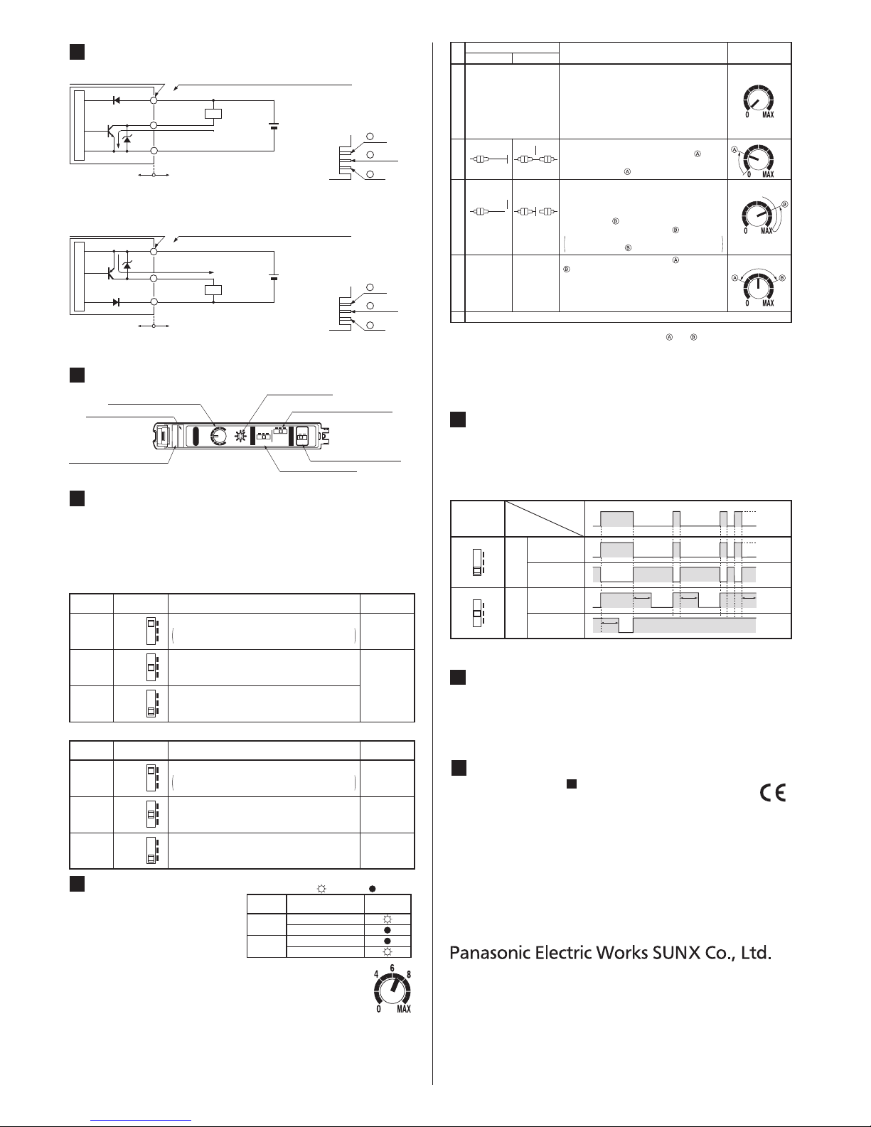
PART DESCRIPTION
7
0
4
6
8
MAX
40
10
OFF
ms
ms
LONG
STD
S-D
L
D
ON
MODE
TIMER
FX-311
Sensitivity indicator
Pointer part: Red backlight
Stability indicator (Green)
Operation indicator (Orange)
Sensitivity adjuster
Mode selection switch (Note)
Operation selection switch
Timer selection switch
INTERFERENCE PREVENTION FUNCTION
11
● This product incorporates an automatic interference prevention function. If the
amplifiers are mounted in cascade, since a different emission timing is automatically set for up to 4 amplifiers, up to 4 sets of fibers can be mounted closely.
Further, even if the amplifiers are mounted closely along with the digital fiber
sensor FX-30□, the interference prevention function works. However, in case both
models of amplifiers are mounted in cascade, mount identical models together.
MODE SELECTION SWITCH
8
●●For FX-311(P), the most suitable sensing mode can be selected according to
the application from LONG (long range distance), STD (standard) or S-D
(reduced intensity). Furthermore, for FX-311B(P) and FX-311G(P), the
sensing mode can be selected from LONG (long range distance), STD
(standard) or FAST (high speed sensing).
Make sure to carry out sensitivity adjustment after mode setting.
<FX-311(P)>
LONG
STD
S-D
LONG
STD
S-D
LONG
STD
S-D
Mode Application
LONG
Used for general sensing application.
Since the emitted light amount is restricted in this mode,
it is suitable for delicate sensing, such as when the
received light is saturated due to too short a sensing
distance or when detecting translucent objects, etc.
STD
Response
time
2ms
250μs
S-D
Mode selection
switch
Used in case long distance sensing is required.
However, the response time is longer than in STD
mode.
<FX-311B(P), FX-311G(P)>
Response
time
LONG
STD
FAST
LONG
STD
FAST
LONG
STD
FAST
150μsUsed in case high speed sensing is required.
Mode Application
LONG
Used for general sensing application.STD
2ms
250μs
FAST
Mode selection
switch
Used in case long distance sensing is required.
However, the response time is longer than in STD
mode.
Notes: 1)
2)
3)
4)
5)
When 'assist function' is not used, the pointer does not flash.
When 'assist function' is not used, the middle point of and is regarded as the optimum
sensitivity point.
In order to protect the mechanism, the sensitivity adjuster idles when over turned, which
may result in a backlash of 1 to 2 divisions.
Depending upon the sensing conditions, stable sensing may be possible at a position
which is slightly shifted from the optimum sensitivity point.
Do not move or bend the fiber cable after the sensitivity adjustment. Detection may
become unstable.
OFF
ON
ON
Sensing method
Operation
Sensitivity indicator
Reflective type
①
③
②
★Make sure that the
operation selection
switch is set to L-ON
(Light ON).
In case 'assist function' is to
be used, switch the operation
selection switch in the order
of
L-ON (Light ON) → D-ON
(Dark ON) → L-ON (Light ON).
Turn the sensitivity adjuster fully counterclockwise. (Minimum sensitivity)
Thru-beam type
In the beam received condition, slowly turn the
adjuster clockwise and find the point where
the sensor is switched ON. The pointer flashes
once at the point . (Note 1)
Beam received Beam received
Beam not
received
Beam not
received
In the beam not received condition, slowly turn
the adjuster further clockwise until the sensor
goes into the ON state again. Once it is switched
on, turn the adjuster counterclockwise a little and
find the point where it is switched OFF. The
pointer flashes twice at the point . (Note 2)
If the sensor does not go into the ON state,
MAX is the point .
Optimum point
Select either L-ON (Light ON) or D-ON (Dark ON) according to your application.⑤
④
- -
Turn the adjuster towards the point from the point
slowly. The pointer starts flashing when it a
proaches the optimum sensitivity point and
flashes faster at the optimum sensitivity point for 3
sec.
This point is the optimum sensitivity point.
(Note 2)
Step
TIMER FUNCTION
10
● This product incorporates an OFF-delay timer function. The delay time can be
selected as either 10ms. approx. or 40ms. approx. with the timer selection switch.
Since the output is extended by a fixed period, it is useful when the connected
device has a slow response time or when small objects are being sensed and the
output signal width is small.
Note: The diagram shows the case when 10ms delay time is selected.
Delay time T: 10ms approx. (when set to 10ms),40ms approx. (when set to 40ms)
<Time chart>
40
10
OFF
ms
ms
40
10
OFF
ms
ms
ON
OFF
ON
OFF
ON
OFF
ON
OFF
T TT
T
Timer
selection
switch
Output
operation
(Note)
Sensing
condition
Light-ON
Dark-ON
Light-ON
Dark-ON
Light
Dark
Normal
OFF-delay timer
I/O CIRCUIT DIAGRAMS
6
Notes: 1)
2)
The quick-connection sub cable does not have +V (brown) and 0V (blue).
The power is supplied from the connector of the main cable.
50mA max., if 5 amplifiers, or more, are connected together.
● FX-311□ / NPN output type
1
+V
3
Output
2
0V
Terminal arrangement diagram
1
2
3
100mA max.
(Note 2)
Load
(Brown) +V (Note 1)
(Black) Output
+
12 to 24V DC
±10%
-
(Blue) 0V (Note 1)
Users' circuitInternal circuit
Sensor circuit
Terminal No. of connector type
Cable type / Color code of quick-connection cable
Notes: 1)
2)
The quick-connection sub cable does not have +V (brown) and 0V (blue).
The power is supplied from the connector of the main cable.
50mA max., if 5 amplifiers, or more, are connected together.
1
+V
3
Output
2
0V
Terminal arrangement diagram
● FX-311□P / PNP output type
1
2
3
Load
+
12 to 24V DC
±10%
-
100mA max.
(Note 2)
(Brown) +V (Note 1)
(Black) Output
(Blue) 0V (Note 1)
Users' circuitInternal circuit
Sensor circuit
Terminal No. of connector type
Cable type / Color code of quick-connection cable
SENSITIVITY ADJUSTMENT
9
●
●
●
●
Adjust the sensitivity, observing the
operation indicator (orange). However,
since the condition for lighting up of the
indicator depends on the combination of
the sensing condition and the selected
operation of L/D-ON, verify it from the
table on the right.
The sensitivity adjuster is a 12-turn
potentiometer.
The maximum sensitivity is obtained by turning it fully clockwise.
The pointer shows the present sensitivity level.
Assist function
This product incorporates an 'assist function', which helps to easily
search the optimum sensitivity position by flashing of the pointer. In order
to make 'assist function' effective, switch the operation selection switch in the order
L-ON (Light ON) → D-ON (Dark ON) → L-ON (Light ON).
Sensing
condition
Light
Dark
Operation
Operation
indicator
D-ON (Dark ON)
D-ON (Dark ON)
L-ON (Light ON)
L-ON (Light ON)
: Lights up : Turns off
Notes: 1)
2)
3)
'Assist function' cannot be used when adjusting sensitivity for moving objects.
'Assist function' turns off automatically once the sensitivity adjustment has been completed.
In case 'assist function' is not to be used, set the operation selection switch to D-ON (Dark
ON) and wait for 2 sec., or more, to make 'assist function' ineffective.
INTENDED PRODUCTS FOR CE MARKING
12
●
The models listed under ' SPECIFICATIONS' come with CE Marking.
As for all other models, please contact our office.
1
Overseas Sales Division (Head Office)
2431-1 Ushiyama-cho, Kasugai-shi, Aichi, 486-0901, Japan
Phone: +81-568-33-7861 FAX: +81-568-33-8591
Europe Headquarter: Panasonic Electric Works Europe AG
Rudolf-Diesel-Ring 2, D-83607 Holzkirchen, Germany
Phone: +49-8024-648-0
US Headquarter: Panasonic Electric Works Corporation of America
629 Central Avenue New Providence, New Jersey 07974 USA
Phone: +1-908-464-3550
PRINTED IN JAPAN © Panasonic Electric Works SUNX Co., Ltd. 2010
http://panasonic-electric-works.net/sunx
Ramco National
www.PanasonicSensors.com
1-800-280-6933
 Loading...