

Page 1
Installation and Operating Instructions
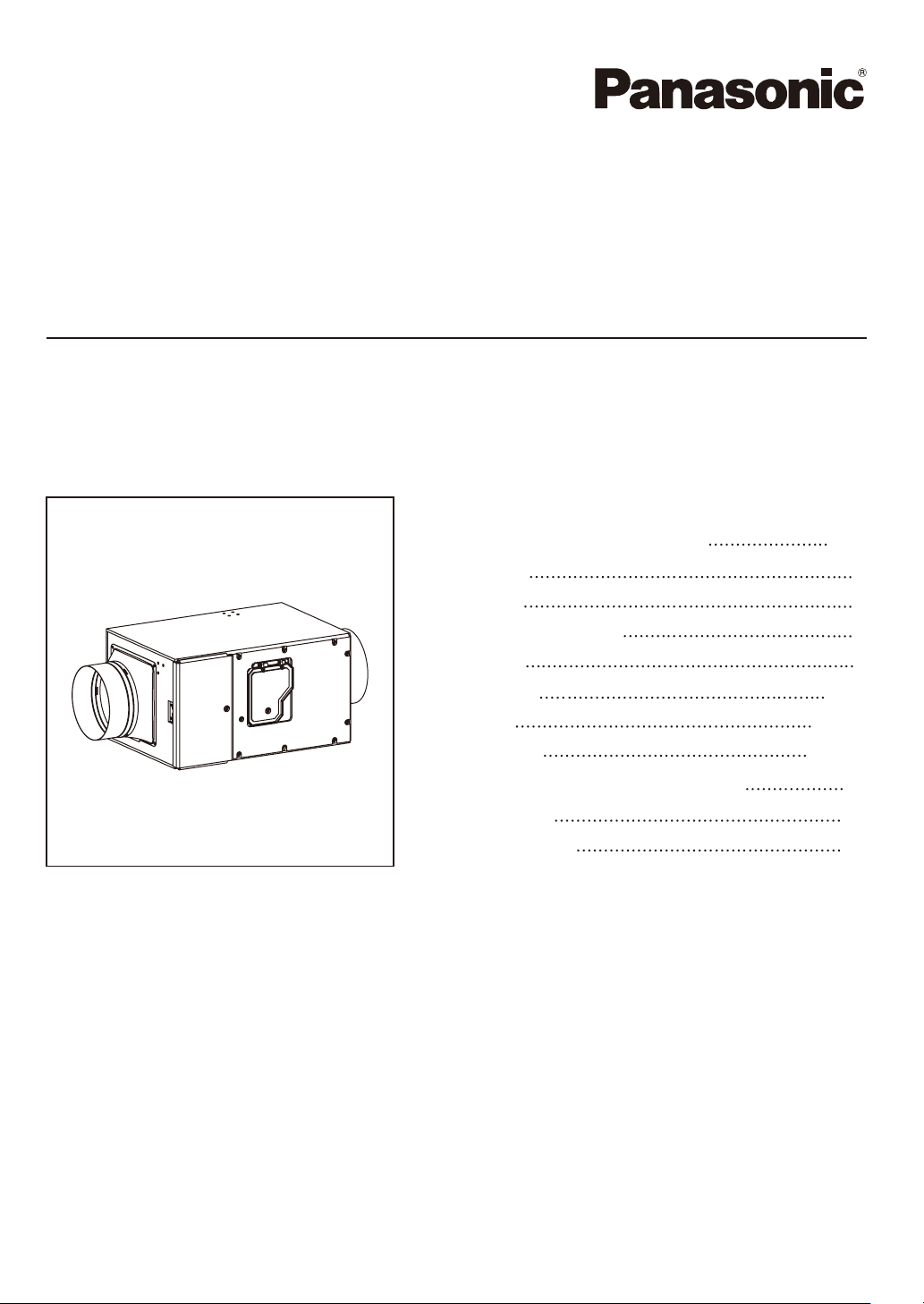
In-Line Fan
Model No.
CONTENTS
GENERAL SAFETY INFORMATION
DESCRIPTION
UNPACKING
SUPPLIED ACCESSORIES
DIMENSIONS
INSTALLATION
OPERATION
MAINTENANCE
PRACTICAL GUIDE TO INSTALLATION
SPECIFICATIONS
PRODUCT SERVICE
FV-15NLFS1
2~4
4
4
5
5
6~8
9~10
10~11
11
12
12
READ AND SAVE THESE INSTRUCTIONS
Thank you for purchasing this Panasonic product.
Please read these instructions carefully before attempting to install, operate or service the
Panasonic product. Please carefully read the “GENERAL SAFETY INFORMATION” (P.2~4) of
this manual before use. Failure to comply with instructions could result in personal injury or
property damage. Please explain to users how to operate and maintain the product after
installation, and this booklet should be presented to users.
Please retain this booklet for future reference.
Page 2
GENERAL SAFETY INFORMATION
For Your Safety
To reduce the risk of injury, loss of life, electric shock, fire, malfunction, and damage to
equipment or property, always observe the following safety precautions.
Explanation of symbol word panels
The following symbol word panels are used to classify and describe the level of hazard, injury,
and property damage caused when the denotation is disregarded and improper use is
performed.
Denotes a potential hazard that could result in death or
WARNING
serious injury.
CAUTION
NOTICE
The following symbols are used to classify and describe the type of instructions to be
observed.
This symbol is used to alert users to a specific operating procedure that must not be
performed.
This symbol is used to alert users to a specific operating procedure that must be
followed in order to operate the product safely.
This symbol is used to alert users not to disassemble the equipment.
This symbol is used to alert users to make sure of grounding when using the
equipment with the grounding terminal.
Denotes a hazard that could result in minor injury.
Denotes a hazard that could result in property damage.
WARNING
TO REDUCE THE RISK OF FIRE, ELECTRIC SHOCK OR PERSONAL INJURY, OBSERVE THE
FOLLOWING :
Do not use this product with any solid-state control device. Solid-state controls may
cause harmonic distortion which can cause motor humming noise.
Do not install with a method which is not approved in the instructions.
Do not disassemble the product for reconstruction. It may cause fire or electric shock.
Use this unit only in the manner intended by the manufacturer. If you have any
questions, contact the manufacturer.
Before servicing or cleaning product, switch power off in control box and lock the
service disconnecting means to prevent power from being switched on accidentally.
When the service disconnecting means cannot be locked, securely fasten a prominent
warning device, such as a tag, to the service panel.
Installation work and electrical wiring must be done by qualified person(s) in
accordance with all applicable codes and standards, including fire-rated construction.
2
Page 3
GENERAL SAFETY INFORMATION
Sufficient air is needed for proper combustion and exhausting of gases through the
flue (chimney) of fuel burning equipment to prevent backdrafting. Follow the heating
equipment manufacturer’s guideline and safety standards such as those published by
the National Fire Protection Association (NFPA), and the American Society for Heating
Refrigeration and Air Conditioning Engineers (ASHRAE) and the local code authorities.
When cutting or drilling into ceiling, do not to damage metal objects, electrical
wiring and other hidden utilities.
Ducted fans must always be vented to the outdoors.
Ceiling must be subjected to static load more than five times the weight of the product.
A statement to the effect that when the product is to no longer be used, it must
not be left in place but remove, to prevent it from possibly falling.
Never place a switch where it can be reached from a tub or shower.
The product must be properly grounded.
CAUTION
Do not kink the power cord.
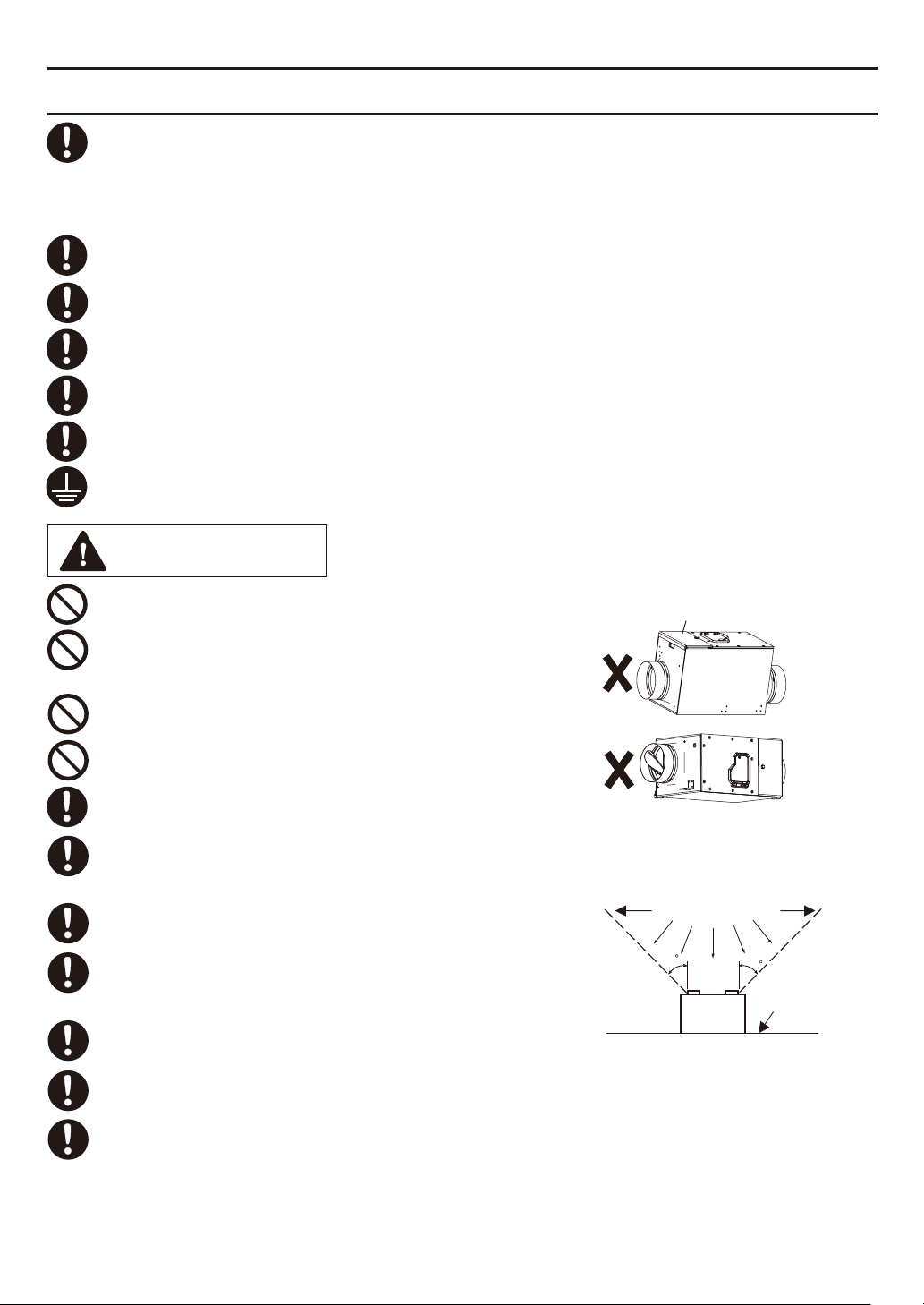
Do not install the product as the directions
shown in right. Otherwise, it may cause electric
shock.
(Fig.A)
Not for use in cooking area. (Fig.B)
This fan shall not be installed behind a suspended floor/
ceiling or a structural wall, ceiling, or floor.
Install this product in the area where the temperature
is between14 °F (-10 °C)~104 °F (40 °C).
The special-purpose or dedicated parts, such as
mounting fixtures, must be used if suchparts are
provided.
Make certain that the electric service supply voltage
is AC 120 V, 60 Hz.
Follow all local electrical and safety codes, as well as
the National Electrical Code (NEC) and the
Occupational Safety and Health Act (OSHA).
Always disconnect the power source before working
on or near the fan or motor.
Protect the power cord from sharp edges, oil, grease,
hot surfaces, chemicals or other objects.
Put the product on the hanger securely. Otherwise, it
may drop.
Maintenance board
to be upside
Fig. A
(Cooking area)
Do not install above or
inside this area
4
5
4
Cooking
equipment
5
Floor
Fig. B
3
Page 4
GENERAL SAFETY INFORMATION
NOTICE
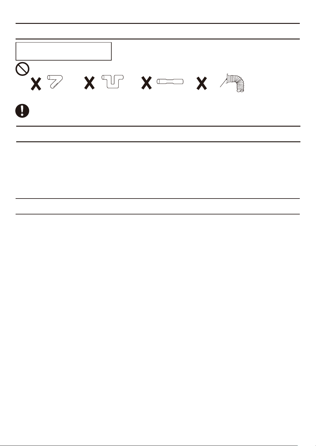
Do not install the product where ducts are configured as shown below.
Adaptor
Excessive bending Successive bending Squeezed duct Bend close to duct adaptor
Please install the tube cover or similar items at the air inlet, otherwise it may cause the
entry of foreign matter or rain, affecting product performance.
DESCRIPTION
This product uses a sirocco fan driven by a DC motor powered by an integral transformer.
The motor is designed to have long operating life, high dynamic response, higher speed
ranges with saving energy. The blower uses a high-capacity sirocco fan developed to reduce
the noise level.
UNPACKING
Unpack and remove product carefully from carton.
Refer to the supplied accessories list to verify that all parts are present.
4
Page 5

SUPPLIED ACCESSORIES
Part name
Hanger
Screw
(M4X8)
Installation and
operating instructions
Limited warranty
DIMENSIONS
3 3/4 (97)
4 3/8 (112)
Air
flow
23 3/8 (594 )
15 3/4 (399)
Appearance
Quantity
3
10
1
1
Unit : inch (mm)
8 3/4 (223)
3 3/4 (97)
Φ5 7/8 (148)
4 3/8 (112)
Part nameNo. Part nameNo.
1
Pre-filter
Sub-efficient filter
2
Main PCB
3
Motor
4
5
Sirocco fan
1 2
3
910
Damper
6
7
Power cord
Adaptor
8
Control box cover
9
10
Maintenance board
Φ5 7/8 (148)
5
4
8
4 5/8 (119)
6
11 (282)
7
5
Page 6

INSTALLATION
Before installing please choose the installation direction.
You can install the product with maintenance board towards down or towards side. (Fig.1,
Fig.2) If there are joists on ceiling, you should install it with the maintenance board towards
down, otherwise you may can not to maintain filter.
Maintenance board towards down
Maintenance board towards side
(Not applicable for ceiling with joists)
Maintenance
board
Fig.1
Maintenance
board
1-1 Install with the maintenance board towards down
1. Fix the hangers (3 pcs) on fan body by screws.
(Fig.3)
2.Install hanger bolts on ceiling, and put washers
and nuts on bolts. (Hanger bolt, nut and washer
should be M8-M10 and no provided.) (Fig.4)
6 3/8 (162)
3 1/2 (90)
Unit : inch (mm)
Hanger
(Fix by 4
screws)
Fig.2
Hanger (Fix
by 3 screws)
Hanger (Fix by 3 screws)
Ceiling
Fig.3
10 1/2 (267)
7 (182)
2 7/8 (74)
7/8 (22) 7/8 (22)
1/2 (12)
3.Install the product on hanger bolts and fix the
nuts tightly. (Fig.5)
Note
Please use the spirit level to adjust the body, to
ensure that the height of the three hangers
within ± 2 mm.
6
1 (25)
3-Hanger
bolts
Hanger
Nut
Washer
Nut
Fig.4
Fig.5
Page 7

INSTALLATION
4.Install Φ6 inch ducts.
(1) Connect the circular duct (suggest using
the insulated flexible duct) to adaptor by
mastic or approved foil tape.
Place/wrap insulation around duct and/or
fan in order to minimize possible
condensation buildup within the duct.
(Fig.6)
Note
Install the exterior duct with a declining
slope toward outer side at least 1/100.
Install the interior duct with a declining
slope toward inner side at least 1/100.
(Fig.6)
5.Set an square inspection hole
of 450 mm or more under the
maintenance board. (Fig.7)
Interior duct
Mastic or
approved foil
tape
Adaptor
Exterior duct
Hanger
Adaptor
Fiberglass insulation
Unit : inch (mm)
Mastic or
approved foil
tape
Fig.6
17 3/4 (450)
Square inspection hole
>1 1/4 (30)
CeilingCeiling
17 3/4 (450)
Square inspection hole
1 5/8 (40)
Fig.7
6.Twist hand screw open maintenance board and pull out the sub-efficient filter,
fill in beginning time on sub-efficient filter, then install back. (Refer Fig.13~15 on P.10~11)
7
Page 8

INSTALLATION
1-2 Install with the maintenance board towards side
Note
This method can not applicable for ceiling
with joists.
1. Fix the hangers (3 pcs) on fan body by screws.
(Fig.8)
2.Install hanger bolts on ceiling, and put washers
and nuts on bolts. (Hanger bolt, nut and washer
should be M8-M10 and no provided.) (Fig.9)
Unit : inch (mm)
2 1/2 (65)
1/2 (12)
17 1/2 (443)
4 3/8 (110)
8 7/8 (224)
3 1/2 (90)
1/2 (12)
3 (78)
3.Install the product on hanger bolts and fix the
nuts tightly. (Fig.10)
3-Hanger
bolts
1 (25)
Hanger (Fix
by 3 screws)
Hanger (Fix by
3 screws)
Hanger (Fix by
4 screws)
Fig.8
Ceiling
Nut
Washer
Nut
Fig.9
Note
Please use the spirit level to adjust the body, to
Hanger
ensure that the height of the three spreaders
within ± 2 mm.
4.Install the ducts. (It is same with step 4 in P.7)
5.Set an square
Unit : inch (mm)
inspection hole of
450 mm or more
beside and below the
Maintenance
board
maintenance board.
(Fig.11)
17 3/4 (450)
Square inspection hole Ceiling
17 3/4 (450)
Square inspection hole Ceiling
6.Twist hand screw open maintenance board and pull out the sub-efficient filter, fill in
beginning time on sub-efficient filter, then install back. (Refer Fig.13~15 on P.10~11)
Fig.10
Fig.11
8
Page 9

OPERATION
Insert power cord plug into
power socket, then open
Control box cover
”I” is on
“O” is off
the control box cover and turn
on the main switch. (Fig.12)
I
O
Main switch
Port receptacle for add-on Module provides additional
features. (Module sold separately)
For details, please consult Panasonic Call Center
Control panel
1
Running indicator
Telephone : 1-866-292-7299 (USA)
1-800-669-5165 (Canada)
When the indicator is on green, indicates the product is running.
2
Filter indicator
The indicator will light on red when the accumulated running
time is up to 90 days. When the indicator is on (with buzzer
1
sound), indicates need to maintain filters.
Note
2
(1)The indicator will be on when the product accumulated
running time reaches to 90 days. The buzzer will sound
every hour and 10 seconds in an hour.
4
(2)If you want to turn off the indication of buzzer, please
press filter reset button about 3 seconds until there is the
sound of a long beep. Press filter reset button about 3
seconds again until there is sound of two quick beeps, the
buzzer indication will be turned on again.
5
(3)If you want to cancel buzzer sound when sleeping, you
just need to turn off the wall switch. The buzzer will
continue to sound when the product is turned back on and
will not stop until the filter has been maintained and the
filter alarm has been reset.
6
(4)When the the running indicator or filter indicator blinks, means
the product failure.
3
Filter reset button
Press the button after filter maintenance for resetting accumulated running time and the
filter indicator will light off, the buzzer will turn off.
4
Air volume dial switch
Adjusting the product air volume by this dial switch, you can choose 50, 60, 70,
80, 90, 100, 110, 130, 150 CFM.
Default setting : 80 CFM
5
Humidity dial switch
Adjusting the humidity protection value of the product by this dial switch, you can choose
from 30 %RH~80 %RH (stepless) or turned to OFF position.
Default setting : 80 %RH
If the product inside humidity detected by sensor is over than setting value, the fan will
stop for 60 minutes, then according to the detected value to determine whether to
operate.
If the switch is turned to OFF position, the humidity sensor detection function will be
disabled.
Fig.12
3
9
Page 10

OPERATION
6
Temperature dial switch
Adjusting the temperature protection value of the product by this dial switch, you can
choose 15 °F~40 °F (stepless) or turned to OFF position.
Default setting : 15 °F
If the product inside temperature detected by sensor is lower than setting value, the fan
will stop for 60 minutes, then according to the detected value to determine whether to
operate.
If the product inside temperature detected by sensor is higher than 95 °F (35 °C), the fan
will stop for 60 minutes, then according to the detected value to determine whether to
operate.
If the switch is turned to OFF position , the temperature sensor detection function will
be disabled.
Note
The humidity and temperature value detected by sensor may be different from outside.
MAINTENANCE
CAUTION
To avoid injury or electric shock, turn off the main switch in control box to stop the fan
before checking, cleaning or replacing filter.
To ensure product running normally, routine maintenance must be performed every
3 months.
Please wear gloves to avoid pinching fingers during maintenance.
When cleaning or replacing filters, dust, insects, etc. attached on the filters may fall.
Please pay attention to the protection of eyes and so on.
Open the control box cover by twist hand
1
1.
screw. (Fig.13)
2
Turn off main switch. (Fig.13)
3
Twist hand screw open maintenance board.
(Fig.13)
2.Pull out the pre-filter, clean it with water once in
3 months when filter indicator lights on with
buzzer sound “Pi-Pi-Pi-
...
”. (Fig.14)
3
Pre-filter
1
2
Fig.13
Fig.14
10
Page 11

MAINTENANCE
3.Pull out the sub-efficient filter, clean it with
vacuum cleaner once in 3 months when filter
indicator lights on with buzzer sound “Pi-Pi-Pi Replace it once in 6 months when filter indicator
lights on with buzzer sound “Pi-Pi-Pi-
...
”. (Fig.15)
Please fill in beginning time on
new filter before replacing.
...
”.
Sub-efficient
filter
BEGINNING TIME:
Note
AIR FLOW
Please replace sub-efficient filter by Panasonic
Model FV-FL0815NL1or FV-FL1315NL1. If you do
not use the Panasonic filter will result in poor
Fig.15
performance.
4.Install back the filters and close the maintenance
board by twist hand screw. Please make sure that
the arrow direction on sub–efficient filter is same
as the “Air flow” mark on name plate. (Fig.15)
5.Turn on main switch, press filter reset button with
sound of “Pi-”, then filter indicator and buzzer
sound will be off. Close the control box cover by
Fig.16
twist hand screw.(Fig.16)
PRACTICAL GUIDE TO INSTALLATION
Properly insulate the area around the fan to
minimize building heat loss and gain. (Fig.17)
Loose fill or batt insulation can be placed directly
over the fan housing in the attic. Our fans
and fan/light combination units do not create
excessive heat that is a common problem with
recessed light fixtures or some competitor’s fan/
light combination. Our efficient, cool-running
motors and our fluorescent lamps do not create
enough ambient heat to be subjected to these
limitations. The ducting from this fan to the
outside of the building has a strong effect on the
air flow, noise and energy use of the fan. Use
the shortest, straightest duct routing possible for
best performance, and avoid installing the fan with smaller ducts than recommended.
Insulation around the ducts can reduce energy loss and inhibit mold growth. Fans installed
with existing ducts may not achieve their rated air flow.
6 inch roof jack,
wall cap, or soffit vent
with backdraft damper
Mechanically connect duct to
termination and seal with mastic
or approved foil faced tape
2-3 ft straight run before elbow
In attic installation,
caulk box to drywall
A short piece of flexible
duct helps alignment
and absorbs sound.
Use clamps plus mastic
or approved foil faced
tape at all flex joints.
Foil tape tightly
covers all metal
duct joints.
(Glue PVC joints)
Insulation
Fig.17
11
Page 12

SPECIFICATIONS
Air
direction
Supply
Voltage
(V)
Frequency
(Hz)
60
Duct
(inch)
6 0.2”WG120
Static
pressure
Air volume
(CFM)
50/50*
60/60*
70/70*
80/80*
90/90*
100/100*
110/110*
130/130*
150/150*
Power
consumption
(W)
8/8.2* 969/989*
9/9.3*
10/10*
12/12.4*
13/13.5*
15/15.3*
16/16.7*
21.5/22.6*
27.1/27.3*
992/1012*
1022/1033*
1030/1067*
1056/1086*
1101/1121*
1122/1152*
1202/1235*
1296/1314*
Speed
(rpm)
Weight
kg)
Ib.(
13.4
(6.1)
Performance based on the MERV8 filter (FV-FL0815NL1), and data with “*” is a reference
datas when using the MERV13 filter (FV-FL1315NL1).
Air volume performance based on HVI Procedures 916 and 920.
PRODUCT SERVICE
Warning Concerning Removal of Covers.
The unit should be serviced by qualified technicians only.
Your product is designed and manufactured to ensure a minimum of maintenance.
Should your unit require service or parts, call Panasonic Call Center at 1-866-292-7299 (USA)
or 1-800-669-5165 (Canada).
Two Riverfront Plaza, Newark, NJ 07102
www.panasonic.com
Panasonic Corporation 2018
12
5770 Ambler Drive, Mississauga, Ontario L4W 2T3
www.panasonic.com
Printed in China
Issue date:01/2018
P0118-0 15NLF4051
 Loading...