

Page 1
INSTALLATION
INSTRUCTIONS
Ventilating Fan/Light Combination
FV-07VQL3
FV-08VQL3
FV-11VQL3
READ AND SAVE THESE INSTRUCTIONS
Please read instructions carefully before attempting to install, operate or service the
Panasonic Ventilating Fan/Light Combination. Failure to comply with instructions could
result in personal injury and/or property damage. Please retain this booklet for future
reference.
Table of Contents
List of components
Description
Dimensions
Specifications
Unpacking
General safety Information
Installation I (Joist mounting Installation)
Installation II (Wooden header Installation)
Installation III (Between joist mounting Installation)
Installation IV (ln existing construction)
Maintenance I (Replacement of fluorescent lamp or night lamp)
Maintenance II (Cleaning)
Product Service
Pages
2
2
2-3
3
3
3-4
5-8
9
10-13
14
14
15
16
Page 2
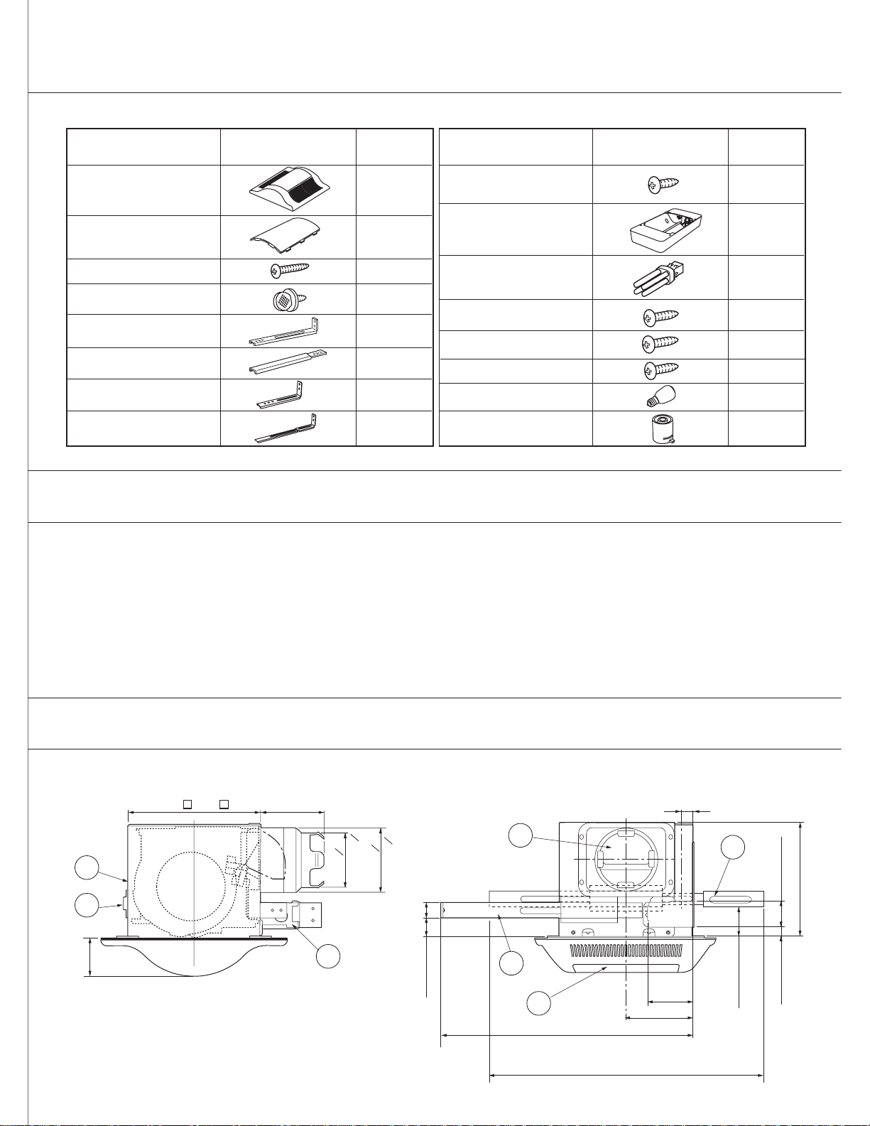
List of components
FV-07VQL3, FV-08VQL3, FV-11VQL3
Part name Drawing Quantity
Grille
Lamp cover
Long screw (M4 x 30)
Thumb screw
Installation bracket
Installation bracket
Installation bracket
Installation bracket
*
**
**
*
*
1
1
10
2
1
1
1
1
Part name Drawing Quantity
Screw (M4 x 6)
*
Light unit
13W Fluorescent Lamp
Short screw (M4 x 12)
Plastic screw (M4 x 13)
Short screw (M4 x 10)
4W incandescent lamp
*
**
Spacer
2
1
2
2
3
1
1
4
Description
These Panasonic ceiling mount ventilating fan models use a sirocco fan driven by a capacitor motor.
The motor is designed to have an extended service life with reduced energy consumption.
It also incorporates a thermal-cutoff for safety. The grille can be quickly detached from the main unit. A damper for
preventing air counterflow is provided. The blower uses a high-capacity sirocco fan developed to reduce the noise
level.
The light unit is an energy-saving, lighting device which uses two 13W fluorescent lamps and produces almost the
same illumination as a standard 100W incandescent lamp.
Dimensions
FV-07VQL3, FV-08VQL3, FV-11VQL3
230
5
17
73 (2 7/8")
() ( )
9"
108
4 1/4"
0
94
3
0
0
0
110
4 3/8"
()
3 1 1/16"
()
34 (1 1/8") 32 (1 1/4")
2
6
10
15
350 - 430(13 7/8" - 17")
550 - 640(22" - 25")
350 - 430(13 7/8" - 17")
117(4 5/8")
22 (7/8")
79(3 1/8")
Unit: mm (inch)
11
45 (1 7/8")
16.5 (5/8")
45 (1 3/4")
200 (7 7/8")
Page 3
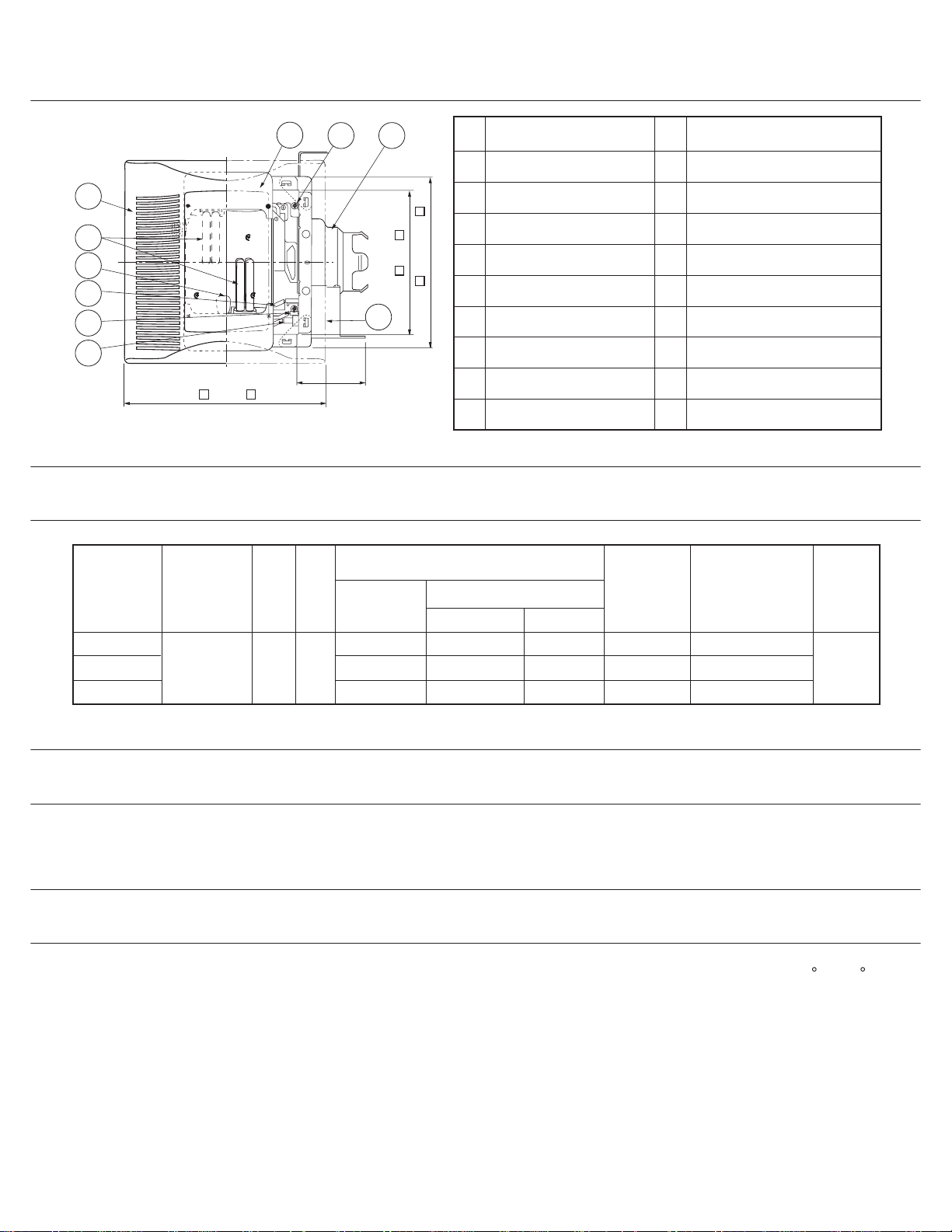
Dimensions continued
1
14
16
7
8
9
330 (13" )
Specifications
Model Air direction V Hz
13
12 2
4
105(4 1/4")
Fan unit
No.
1
Grille
Adapter
2
Junction box
3
4
Junction box cover
5
228 (9" )
268 (10 5/8" )
Power consumption* (W)
Fluorescent lamp
Body
Damper
6
Motor connector
7
Night lamp connector
8
9
13W lamp connector
Light unit
Part name
Night lamp
Speed*
(RPM)
No.
Installation bracket ,
10
11
Installation bracket
12
Thumb screw
13
Light unit
14
Fluorescent lamp (13W x 2)
Lamp cover
15
16
Night lamp
Bracket cover
17
Air deliver at 0.1"WG
Part name
(4W x 1)
(CFM)
***
* , *
Weight
lb.(kg)
FV-07VQL3
FV-08VQL3
FV-11VQL3
* At 0.0" Static pressure, (Pa)
18
60120Exhaust
20
26
26
26
26
4
4
4
725
875
995
70
90
110
17.4
(7.9)
Unpacking
Unpack and carefully remove unit from carton. Refer to the Supplied components list to verify that all parts are
present.
General safety information
1.
Do not install this ventilating fan/light combination in ducts where air temperature may exceed 104 F. (40 C)
2.
Make certain that the electric service supply voltage is 120V 60Hz.
Follow all local electrical and safety codes, as well as the National Electrical Code (NEC) and the Occupation
3.
Safety and Health Act (OSHA).
Always disconnect the power source before working on or near the fan, motor or light fixture.
4.
3
Page 4
General safety information continued
Protect the power cord from sharp edges, oil, grease, hot surfaces,
5.
chemicals, or other objects.
6.
Do not kink the power cord.
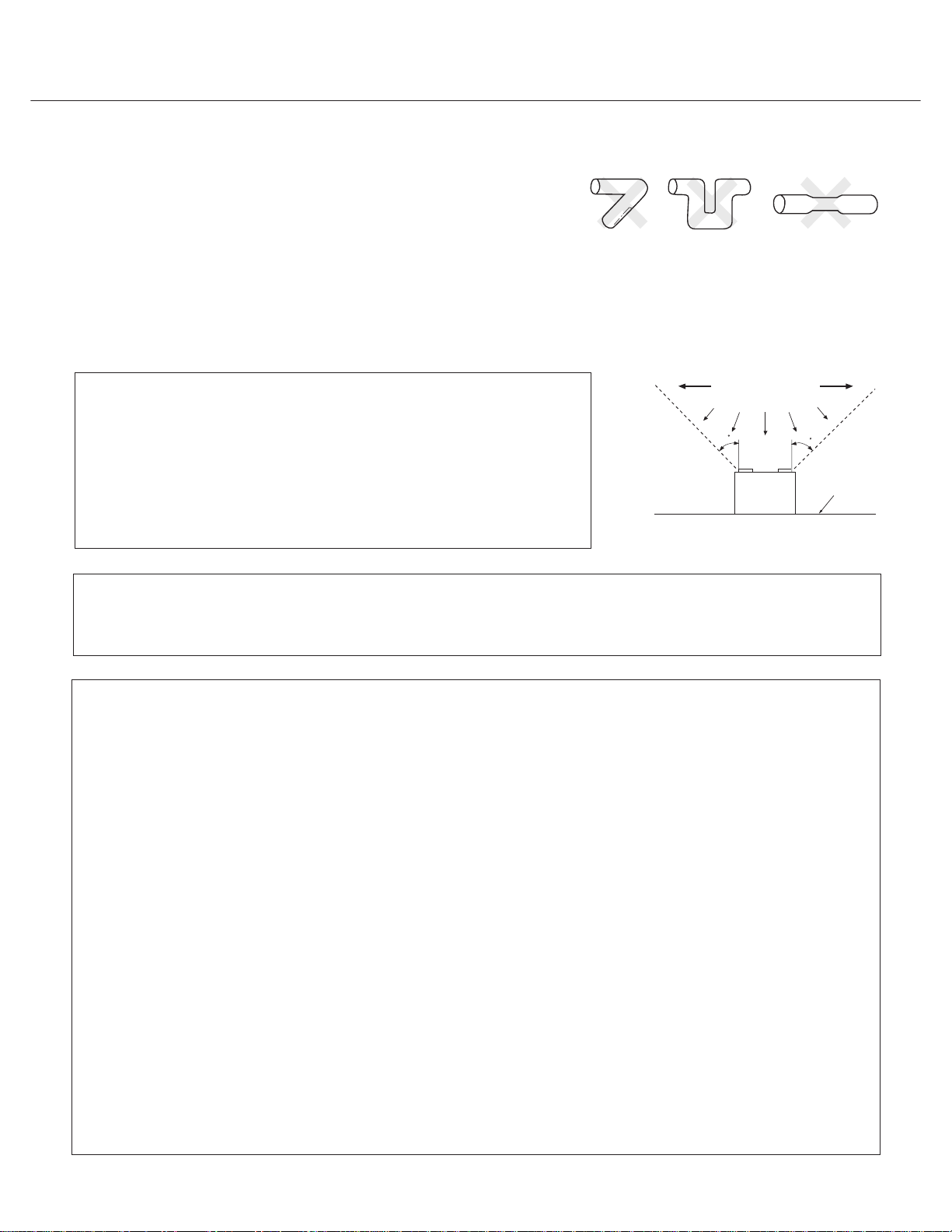
7.
Do not install the unit where ducts are configured as shown in Fig. A.
Provide suction parts with proper ventilation.
8.
9.
This unit is acceptable for use over a bathtub or shower when installed
in a GFCI protected branch circuit.
CAUTION:
Fig. A
(Cooking area)
Do not install above or
inside this area.
1. For general ventilating use only. Do not use to exhaust hazardous
45
45
or explosive materials and vapors.
2. Not for use in cooking area. (Fig. B)
3. This product must be grounded.
Cooking
equipment
Fig. B
Floor
WARNING:
Do not install this equipment in heating or air conditioning, air processing, or any other recirculated air ductwork.
WARNING:
To reduce the risk of fire, electric shock, or injury to persons, observe the following;
A.
Use this unit only in the manner intended by the manufacturer. If you have any questions, contact the
manufacturer.
B.
Installation work and electrical wiring must be done by qualified person(s) in accordance with all applicable
codes and standards,including fire-rated construction.
Sufficient air is needed for proper combustion and exhausting of gases through the flue (chimney) of fuel
C.
burning equipment to prevent backdrafting. Follow the heating equipment manufacturer's guideline and
safety standards such as those published by the National Fire Protection Association (NFPA), and the
American Society for Heating Refrigeration and Air Conditioning Engineers (ASHRAE), and the local code
authorities.
D.
When cutting or drilling into wall or ceiling, do not damage electrical wiring and other hidden utilities.
E.
Ducted fans must always be vented to the outdoors.
F.
If this unit is to be installed over a tub or shower, it must be marked as appropriate for the application.
G.
Do not use this unit with any solid-state control device.
H.
Before servicing or cleaning unit, switch power off at service panel and lock the service disconnecting
means to prevent power from being switched on accidentally. When the service disconnecting means
cannot be locked, securely fasten a prominent warning device, such as a tag, to the service panel.
I.
NEVER place a switch where it can be reached from a tub or shower.
J.
Do not insulation rated greater than R40.
4
Page 5
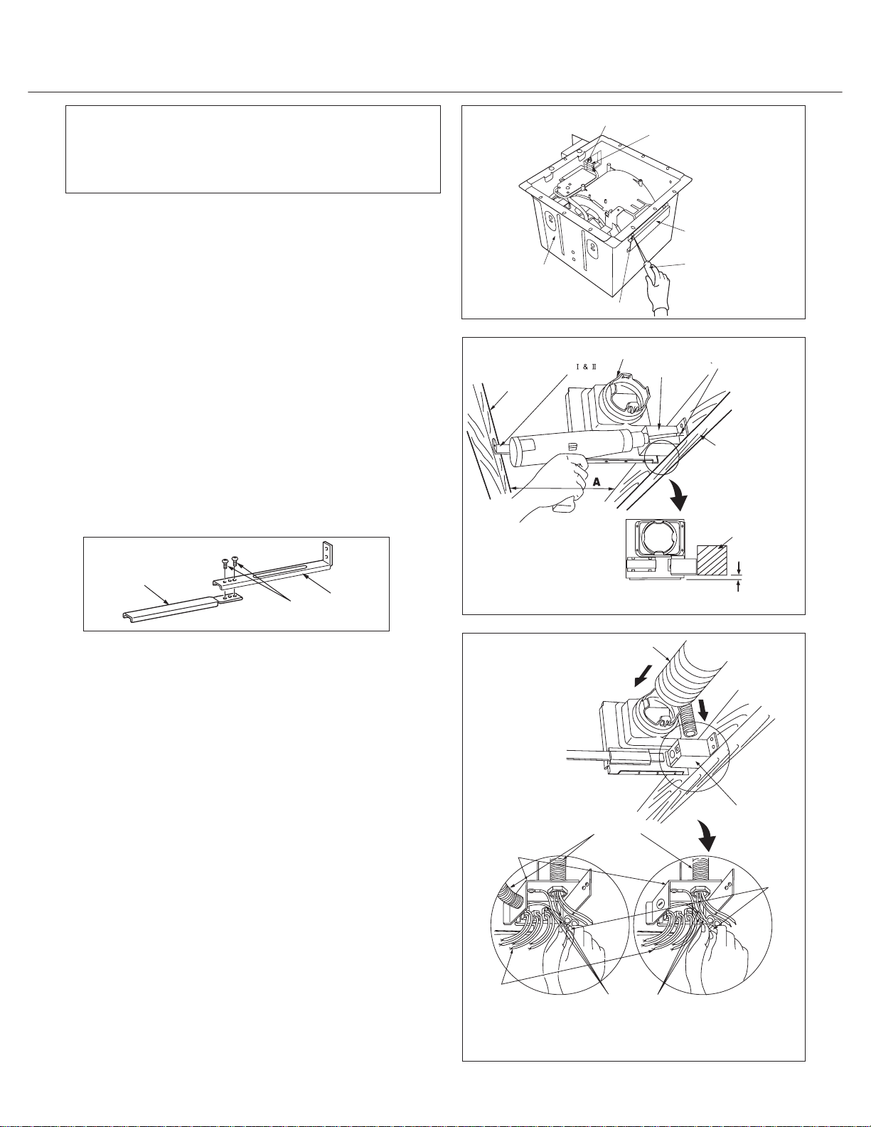
Installation (Joist mounting installation)
I
CAUTION:
Remove the bracket cover by loosening 4 (M4x6)
screws before installation
1.
Disconnect plug connector from receptacle before
starting installation.
2.
Remove adapter from body and fix to ceiling joists
using long screws (M4X30). Slide the installation bracket
* into slot next to the junction box. If longer extension
is needed, assemble brackets * and * as shown below.
Secure the angular end of the bracket to the ceiling
joist. (See Fig.2.) Make sure the adapter is level and
square (perpendicular) with the joists.
Keep the distance B (21.6mm,0.85 inch) for the thickness
of ceiling board.
(Fig.1)
(Fig.1)
(Fig.2)
Fan body
Ceiling joist
Installation
bracket
Receptacle
Screw
Adapter
Plug connector
Junction box
Bracket cover
Screw driver
Fig. 1
Long screw
Ceiling joist
Ceiling joist
Installation bracket
3.
Remove junction box cover and secure conduit to
II
Installation
bracket
Screw
(M4x6)
I
I
junction box knockout hole.(7/8 inch)
4.
Refer to wiring diagram.
Using wire nuts, connect house power wires to ventilating
fan wires:
black to blacks; white to whites; green to greens.
Replace junction box cover.
(Fig.3)
(Fig.3)
Junction box
Lead wires
Separate connection
B
Fig. 2
Duct
Junction box cover
Conduit
Wire nut
Green wires
Lump-sum connection
Fig. 3
5
Page 6

Installation (Joist mounting installaton) continued
I
Wiring Diagram
Light unit
Fan unit
Red
Capacitor
Black
Motor
Night Lamp
Slide 4" dia. duct onto adapter and secure with tape.
5.
6.
Remove ceiling section.
Black
White
Green
Ballast
Green
Lamp Lamp
Ballast
Power supply
AC 120V 60 Hz
Junction box
Black
White
Earth ground
Power Supply
AC120V 60Hz
(Fig.4)
235
mm (inches)
(9.25)
235
(9.25)
Adapter
CAUTION:
Mount junction box cover carefully so that lead wires
are not caught.
Adapter
Tape
Ceiling
Ceiling joist
Duct
Fig. 4
NOTE
When connecting the light unit and the fan unit to the
different power sources, connect the conduit to their
respective junction box shown in Fig. 3 on page 5 and
connect the wires according to the wiring diagram.
Two 2-pin sockets (white and black) is used in the
light unit.
A 3 pin socket (white,black and green) is used in
the fan unit.
Connect the earth grounding wires (green) first.
WARNING:
Make all electrical connections in accordance
with the National Electric Code (NEC) and all
local electrical codes.
6
Page 7

Installation (Joist mounting installaton) continued
IMPORTANT:
I
Insert fan body into ceiling.
7.
Make sure that body "Claws" are properly inserted
into adapter slots.
In case body and blower are installed separately.
(Fig. 5)
Tape
Remove 3 screws.
(Fig.6-1)
Remove blower section.
(Fig.6-2)
Insert fan body into ceiling.
(Fig. 5)
Mount blower section
and fix with 3 screws.
(Fig.6-3)
Blower section
Frame section
Screws
Frame section
Fig. 6-1
Fig. 6-2
Adapter slots
Claws
Claws
Duct
Ceiling
Body
Fig. 5
IMPORTANT:
Make sure that frame is
properly inserted into
groove of blower section.
Frame
section
Blower
Groove
Fig. 6-3
Secure fan body to adapter using two thumb screws.
8.
(Fig. 7)
Ceiling
Thumb screws
Fig. 7
7
Page 8

Installation (Joist mounting installaton) continued
Insert plug connector I to receptacle I.
9.
I
(Fig. 8)
Receptacle III
(for 13w lamp)
Fix fan body to ceiling joists using long screws
10.
(M4X30) in horizontal or vertical direction.
Insert the plug connector II , plug connector III into
11.
the receptacle II, receptacle III respectively, and
attach the light unit to the fan unit with 3 plastic screws
(M4X13) and one short screw I (M4x12) .
(Fig. 9)
(Fig. 10)
Ceiling
Receptacle II
(for night lamp)
Ceiling
Plug connector
Fan
I
Receptacle
(for fan)
I
Fig. 8
Fig. 9
Insert the fluorescent lamps and screw the night lamp
12.
into the light unit.
Insert the lamp cover to the grille and attach the grille
13.
to the fan unit.
Lamp Cover
Grille
Slot
Light unit
Mounting spring
Grille
(Fig. 10)
(Fig. 11)
Fig.11
Short screw
Fluorescent lamp
Plastic screws
4W Night Lamp
Light unit
Receptacle
Plug connector
Plug connector
III
Plug connector
Plug connector
III
II
Receptacle
II
Fig.10
8
Page 9

Installation (Wooden header installaton)
Before installation, secure adapter to fan body using
1.
two thumb screws.
2.
Insert the plug connector II and plug connector III into the
II
(Fig. 12)
receptacle II and receptacle III respectively . Install the light
unit to the fan body by using plastic screws (M4x13)
and one short screw I (M4x12). Insert the fluorescent
lamps and screw the night lamp into the light unit.
(Fig.10, Fig. 12)
3.
Install header between ceiling joists using nails or screws.
(Fig. 13)
Secure the Fan/Light assembly to the header with long
4.
screws (M4X30).
(Fig. 14)
5.
Slide the 4" circular duct onto the adapter and secure
with tape. Remove the junction box cover and secure
conduit to junction box knockout hole. (7/8 inch)
(Fig. 14)
6.
Refer to wiring diagram.
mm(inch)
Using wire nuts, connect house power wires to ventilating
fan wires:
black to blacks; white to whites; green to greens.
Replace junction box cover.
(Fig. 3)
CAUTION:
Mount junction box cover carefully so that lead wires
are not caught.
Ceiling joist
(9 1/4)
Ventilating fan
235
Thumb screws
Fan body
Light unit
Fig. 12
Header
Ceiling joist
345
(13 9/16)
Adapter
Fig. 13
Adapter
Circular duct
Junction box cover
Wiring Diagram
Light unit
Fan unit
Red
Black
Capacitor
Motor
Night Lamp
7.
Finish ceiling work. Ceiling hole should be cut at the
Black
White
Green
Lamp
Ballast
Green
Junction box
Black
White
edge of the flange.
8.
Insert the lamp cover into the Grille and attach the grille
to the fan unit.
Ballast
Power supply
AC 120V 60 Hz
Earth ground
Lamp
Power Supply
AC120V 60Hz
(Fig. 15)
Ceiling
(Fig. 11)
When connecting the light unit and fan unit seperately, read the note on page 6 before making connections.
Long screws
Flange
9
Fig. 14
Fig. 15
Page 10

Installation
(Between joist mounting installation)
III
1. Before installation, secure adapter to fan body by using
two thumb screws.
(Fig. 16)
2. Insert the installation bracket III into slot of the adapter
Thumb screws
Fan body
Fig. 16
side.
(Fig. 17)
3. Insert the installation brackets I and IV into slot.
(Fig. 18)
Fan body
adapter
installation bracket III
Fig. 17
10
installation bracket I
installation bracket IV
Frame
Fig. 18
Page 11

Installation
(Between joist mounting installation) continued
III
4.Insert the fan body between joists.
Make sure the fan body is level and square (perpendicular)
with the joists.
Keep the flange and joists on same level.
(Fig. 19)
Ceiling joist
Ceiling joist
CAUTION:
Joist spacing A should be between 350mm (13 7/8")
1.
and 430mm (17").
2.
Don't fix the junction box flap to the ceiling joist in this
installation.
5. Secure the installation bracket III to ceiling joist using
long screws (M4X30).
(Fig. 20)
Ventilating fan
Ceiling joist
A
350-430mm
(13 7/8"-17")
Adapter
junction box flap
Fig. 19
6. Secure the fan body to ceiling joists using long screws
(M4X30) in horizontal direction with installation bracket
I and IV.
(Fig. 21)
11
Installation bracket
4-Long screws
Installation bracket
III
IV
Ceiling joist
Installation bracket
Fig. 20
I
Ceiling joist
Fig. 21
Page 12

Installation
(Between joist mounting installation) continued
III
7. Secure installation bracket I and IV to the fan body using
short screw I (M4X12) and short screw II (M4X10).
(Fig. 22)
Short screw
Short screw
II
I
Installation bracket
I
8. Slide the circular duct onto the adapter and secure with
tape.Remove the junction box cover and secure conduit
to junction box knockout hole.(7/8 inch)
(Fig. 23)
Refer to wiring diagram on page 6.
9.
Using wire nuts, connect house power wires to ventilating
fan wires:
Black to blacks; white to whites; green to greens.
Replace junction box cover.
(Fig. 3)
CAUTION:
Mount junction box cover carefully so that lead wires
are not caught.
Installation bracket
IV
Adapter
Ceiling joist
Fig. 22
Circular duct
Conduit
Junction box cover
10. Finish ceiling work. Ceiling hole should be cut at the edge
of the frame.
(Fig. 24)
12
Ceiling
235
(9.25)
Flange
235
(9.25)
Fig. 23
Fig. 24
Page 13

Installation
(Between joist mounting installation) continued
III
11. Insert a spacer to metal plate of the fan case and
three spacers to the light unit.
(Fig. 25)
Spacer
Insert the plug connector II and plug connector III
12.
into the receptacle II and receptacle III respectively.
Attach the light unit to the fan unit by 4 long screws
(M4x30).
13.
Insert the fluoresceut lamps and screw the night lamp
into the light unit.
(Fig. 26)
(Fig. 26)
Spacer
Long screws
Fan case
Light unit
Light unit
Plug connector
Plug connector
Fig. 25
Plug connector
Plug connector
III
II
14. Insert the lamp cover to the grill and attach the grill
to the fan unit.
(Fig. 27)
Lamp Cover
Grille
Slot
Light unit
Mounting spring
Grille
Fig.27
13
Fluorescent lamp
Night lamp
Receptacle
III
Receptacle
II
Fig. 26
Page 14

Installation (In existing construction)
IV
Installing the ventilating fan in an existing construction
requires an accessible area (attic or crawl space) above
1.
To install the ventilating fan, follow the procedures
described in Installation I.
the planned location or existing ducting and wiring.
Inspect duct work and wiring before proceeding
2.
with installation.
3.
CAUTION:
Check area above planned installation location to be
sure that:
1.
Duct work can be installed and that area is sufficient
for proper ventilation.
2.
Wiring can be run to planned location.
3.
No wiring or other obstructions will interfere with
installation.
Maintenance (Replacement of fluorescent lamp or night lamp)
I
WARNING:
1.
Disconnect power source before working on unit.
2.
The lamp's glass is fragile. Please handle with
care. To remove lamp, grasp at base and move
Plan suitable location for ventilating fan. (next to
ceiling joist).
Before installation, provide inspection and maint-
4.
enance access at a location that will not interfere
with installation work shown in Installation I.
5.
Remove ceiling section according to Fig. 4 on
page 6.
Install ventilating fan.
6.
Disconnect the connector II or connector III of light
2.
unit.
(Fig. 29)
Connector
II
back and force to loosen.
Do not pull hard on the lamp or you may break the
glass.
3.
4W night lamp has threaded base. Remove by
turning counterclockwise.
III
Connector
Fig. 29
1.
Remove grille. (Squeeze mounting spring and pull down)
Slot
Mounting spring
Gloves
Grille
Change the fluorescent bulbs (Panasonic FDS 13E
(Fig. 28)
3.
27.U/2, 13W or FQ13E 41.U/2, 13W or FQ13E 35.U/2,
13W) or the 4W incandescent lamp, connect the connector
II or connector III and replace the grille.
(Fig. 30)
Fig. 28 Fig. 30
14
Page 15

Maintenance (Cleaning)
II
WARNING:
Disconnect power source before working on unit. Routine maintenance must be done every year.
CAUTION:
1. Never use gasoline, benzene, thinner or any other similar chemicals for cleaning the grille and the
ventilating fan.
2. Do not allow water to enter motor.
3. Do not expose plastic parts to temperature over 140 F (60 C).
Wash and clean grille. (Use non-abrasive kitchen
1.
Remove grille. (Squeeze mounting spring and pull down)
Slot
(Fig. 31)
2.
detergent)
(Fig. 32)
Mounting spring
Gloves
3.
Remove dust and dirt from fan body using a vacuum
Grille
Fig. 31
cleaner. (Remove bulbs if necessary.)
(Fig.33)
Fig. 32
4.
Using a cloth dampened with kitchen detergent,
remove any dirt from fan body. Wipe dry with new
cloth.
5.
Replace bulbs and grille.
(Fig. 34)
(Fig. 27)
Vacuum cleaner
Fig. 33
Fig.34
15
Page 16

Product service
The unit should be serviced by qualified technicians only. No service information is provided for customers. Your
product is designed and manufactured to ensure a minimum of maintenance. However, should your unit ever
require service, a nationwide system of factory service centers and AUTHORIZED INDEPENDENT SERVICE
CENTERS is maintained to support your product's warranty.
(In the U. S.A., call 1-866-292-7292 to locate the Panasonic Authorized Service Center nearest you.)
PANASONIC CONSUMER ELECTRONICS COMPANY
One Panasonic Way, Secaucus, NJ, 07094
PANASONIC CANADA INC.
5770 Ambler Drive, Mississauga, ON L4W 2T3
www.panasonic.ca
16
 Loading...