

Page 1
PEG1312054CE
Version:1301
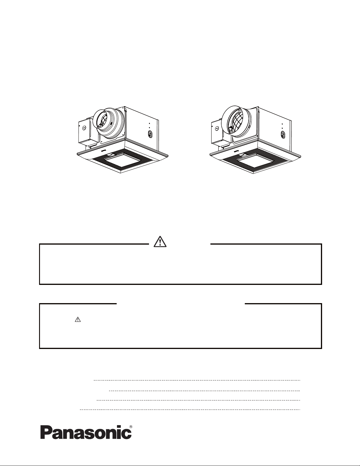
Service Manual
Ventilating Fan
(North America Market)
FV-05-11VKL1
FV-11-15VKL1
WARNING
This service information is designed for experienced repair technicians only and is not designed for use by
the general public. It does not contain warnings or cautions to advise non-technical individuals of potential
dangers in attempting to service a product. Products powered by electricity should be serviced or repaired
only by experienced professional technicians. Any attempt to service or repair the product or products dealt
with in this service information by anyone else could result in serious injury or death.
IMPORTANT SAFETY NOTICE
There are special components used in this equipment which are important for safety. These parts are
marked by in the Schematic Diagrams, Exploded Views and Replacement Parts List. It is essential
that these critical parts should be replaced with manufacturer's specified parts to prevent shock, fire
or other hazards. Do not modify the original design without permission of manufacture.
We suggest to handle such parts after the static electricity prevention.
It is forbidden to touch the PCB parts by bare hands during the repairing process.
CONTENTS
1. Specifications
2. Parts Identification
3.Wiring Diagram
4. Parts List
PAGE
1
2~9
10
11~14
Page 2
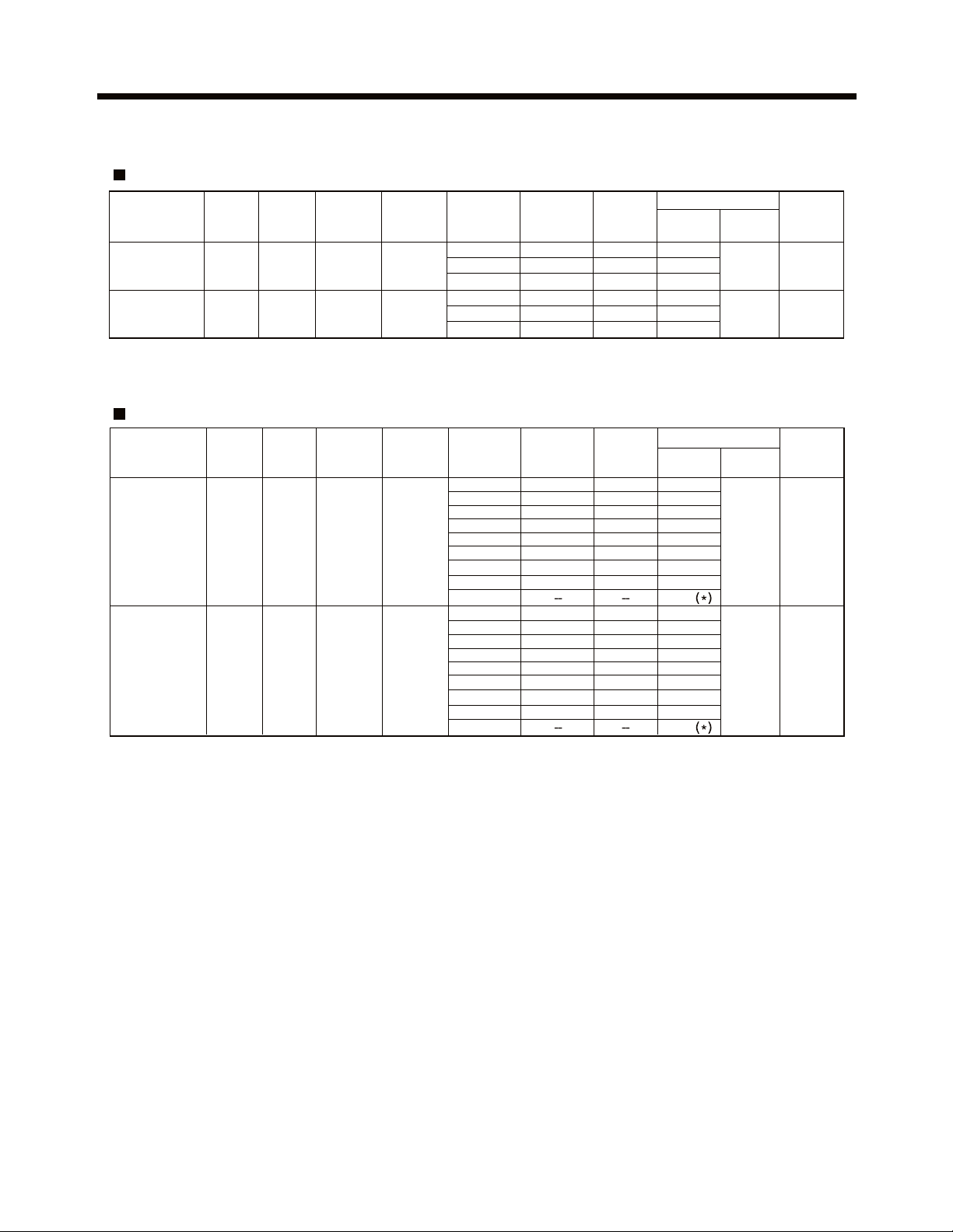
1.Specifications
Specifications for Base Model fans
Duct
diameter
(inches)
4or6
6
Model No.
FV-05-11VKL1
FV-11-15VKL1
Air
direction
Exhaust
Exhaust
Voltage
Frequency
(V)
120 60
120 60
(Hz)
HVI Certified performance based on HVI Procedures 915,916,and 920.
Specifications for Multi Speed fans
Duct
diameter
(inches)
4or6
6120 60
Model No.
FV-05-11VKL1
(Plug-in
FV-VS15VK1)
FV-11-15VKL1
(Plug-in
FV-VS15VK1)
Air
direction
Exhaust
Exhaust
Voltage
Frequency
(V)
120 60
(Hz)
Air volume
at 0.1"WG
(CFM)
50
80
110
130
Air volume
at 0.1"WG
(CFM)
100
90
80
70
60
50
40
30
0
120
110
100
90
80
70
60
50
0
Noise
(sones)
<0.3
<0.3
0.4
<0.3
<0.3
0.6
Noise
(sones)
<0.3
<0.3
<0.3
<0.3
<0.3
<0.3
<0.3
<0.3
<0.3
<0.3
<0.3
<0.3
<0.3
<0.3
<0.3
<0.3
Speed
(rpm)
750
825
965110
650
680
730150
Speed
(rpm)
915
865
825
795
770
750
730
725
665
650
645
640
635
630
625
620
Fan
3.6
6.0
11.0
8.5
12.0
16.5
Fan
8.7
7.0
6.0
4.7
3.9
3.6
2.8
2.5
0.5
9.5
8.5
6.9
5.7
5.0
4.3
4.0
3.2
0.5
Power (W)
Lighting
Power (W)
Lighting
unit
14
14
unit
14
14
Weight
lb.
(k )g
11.5(5.2)
11.7(5.3)
Weight
(k )g
lb.
11.5(5.2)
11.7(5.3)
Reference performance based on HVI Procedures 915, 916,and 920. [(*) Standby wattage.]
1
Page 3
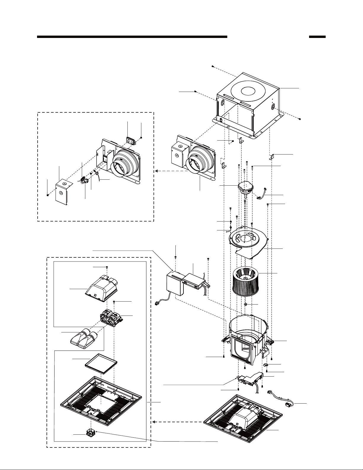
2.Parts Identification
Main Body Section
FV-05-11VKL1
(3pcs)
10
E
11
1
8
A
(3pcs)
3
B
B
7
B
6
D
(4pcs)
4
9
C
5
E
(2pcs)
2
(5pcs)
C
(28)
Main PCB Section
22
(2pcs)
20
23
24
14
F
12
E
21
A
(3pcs)
Base PCB Section
(2pcs)
25
E
13
17
15
16
E
18
19
Ornamental Cover
2
Page 4
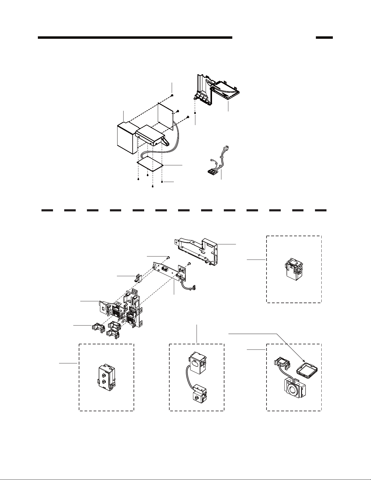
2.Parts Identification
Main PCB Section
G
(3pcs)
26
FV-05-11VKL1
29
E
27
Base PCB Section
G
(2pcs)
33
32
31
(3pcs)
G
(4pcs)
34
28
35
36
Condensation Sensor Module
38
Sensor Cover
37
30
Multi-Speed Control Module
Nite-Glo LED Night Light Module
TM
Motion Sensor Module
1,Please note that above parts with(No.30,36,37,38) are the optional parts bas
on different customer’s request.
2,If install the motion sensor control,please remove the ornamental cover and
replace the sensor cover.
3
Page 5
2.Parts Identification
Packing Section
39
FV-05-11VKL1
45
40
42
44
41
43
(22)
(2pcs)
46
47
4
Page 6

2.Parts Identification
08VSL 3082
Main Label
FV-05-11VKL1
48
51
Not for use in cooking area-See installation
instructions Non destiné à la zone de cuisson -Voir
instructions d’installation.
cocine - Consulte las instrucciones de instalación.
se
//.
No usar en áreas donde
49
52
5350
E78414
US
LISTED
FAN
54
5
Page 7

2.Parts Identification
Main Body Section
FV-11-15VKL1
(3pcs)
D
10
11
1
8
A
(3pcs)
E
(2pcs)
2
B
(4pcs)
9
E
(5pcs)
C
(28)
3
B
7
B
6
C
4
5
Main PCB Section
22
(2pcs)
20
23
24
14
F
12
E
21
A
(3pcs)
Base PCB Section
(2pcs)
25
E
13
17
15
16
E
18
19
Ornamental Cover
6
Page 8

2.Parts Identification
Main PCB Section
G
(3pcs)
26
FV-11-15VKL1
29
E
27
Base PCB Section
G
(2pcs)
33
32
31
(3pcs)
G
(4pcs)
34
28
35
36
Condensation Sensor Module
38
Sensor Cover
37
30
Multi-Speed Control Module
Nite-Glo LED Night Light Module
TM
Motion Sensor Module
1,Please note that above parts with(No.30,36,37,38) are the optional parts bas
on different customer’s request.
2,If install the motion sensor control,please remove the ornamental cover and
replace the sensor cover.
7
Page 9

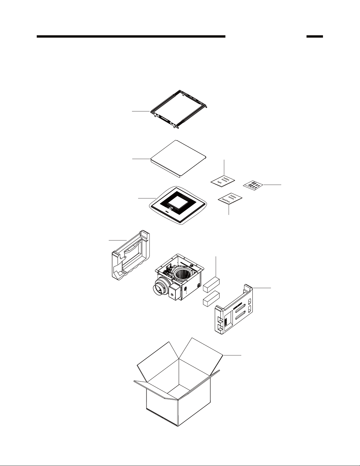
2.Parts Identification
Packing Section
39
FV-11-15VKL1
45
40
42
44
41
43
(22)
(2pcs)
46
47
8
Page 10

2.Parts Identification
08VSL 3082
Main Label
FV-11-15VKL1
48
51
Not for use in cooking area-See installation
instructions Non destiné à la zone de cuisson -Voir
instructions d’installation.
cocine - Consulte las instrucciones de instalación.
se
//.
No usar en áreas donde
49
52
5350
E78414
US
LISTED
FAN
54
9
Page 11

3.Wiring Diagram
FV-05-11VKL1
FV-11-15VKL1
Fan body
DC-Motor
Multi-Speed switch
Pulg ‘N Play
module slot
Pulg ‘N Play
module slot
Pulg ‘N Play
module slot
Green
LED
lamp
(114°C Fuse)
Thermally
protected
Junction box
Black
White
Red
Red
Green
Black
White
Switch for power
Live (Fan)
Neutral
Hi/Low switch:When plug in
Multi-Speed module;
On/Off switch:When plug in
other Plug’N Play modules.
(Non-powered control wires)
Earth ground
Switch for power
Live
(LIGHT)
Neutral
(Power supply)
AC120V 60Hz
(Power supply)
AC120V 60Hz
10
Page 12

4.Parts List
No. Part No. Part Name Q'ty Remark
1 FFV1600138S Frame Assembly 1
2 FFV0000145S Adapter Assembly 1
3 FFV0900062S Connector Plate 1
4 FFV1340008S Earth Lead Wire Assembly 1
5 FFV0900051S Connector Assembly 1
6 FFV0900067S Connector Assembly(L) 1
7 FFV2800021S Junction Cover 1
8 FFV0800001S Casing Support 3
9 FFV3702255S Motor Assembly 1
10 FFV4620109S Motor Lead Wire Assembly 1
11 FFV3702256S Motor Support 1
12 FFV0400114S Blade 1
13 FFV7020021S Nut 1 For Fixing Blade
14 FFV3740030S Main PCB Section 1
15 FFV0790108S Casing 1 Include 4pcs Sponge
16 FFV0960001S Nylon Clamp 1 For Fixing Cord Assembly
17 FFV0410004S Base PCB Section 1 Not Include Multi-Speed Module
18 FFV0730037S Cord Assembly 1
19 FFV3402165S Louver Section 1
20 FFV3420066S Light Kit Cover Assembly 1
21 FFV3420079S Light Kit Section 1
22 FFV3410042S LED Lamp 2 120V/60Hz,7Wattage
23 FFV3420029S Lamp Cover 1
24 FFV2220074S Ornamental Cover 1
25 FFV3402166S Louver Assembly 1
Include Lamp Cover&Ornamental Cover
A FFV7000065S Bind Screw 6
B FFV7000108S Truss Tap Screw 3
C FFV7000203S Earth Lead Wire Screw 2 For Fixing Earth Lead Wire
D FFV7000109S Stainless Steel Screw 4 For Fixing Motor Assembly
E FFV7000089S Truss Tap Screw 11
F FFV7000191S Bind Screw 1 For Fixing Light Kit Cover Assembly
No. Part No. Part Name Q'ty Remark
26 FFV3740027S Main PCB Box 1
27 FFV3740028S Main PCB Assembly 1
28 FFV4620110S Power Lead Wire 1
29 FFV3740014S Main PCB Cover 1
E FFV7000089S Truss Tap Screw 1 For Fixing Main PCB Cover
G FFV7000145S Truss Tap Screw 7 For Fixing Main PCB Assembly
Main Body Section
Main PCB Section
FV-05-11VKL1
11
Page 13

4.Parts List
No. Part No. Part Name Q'ty Remark
30 FFV5530071S Multi-Speed Module 1
31 FFV0900063S Connector Cover 3
32 FFV0410001S Base PCB Cover 1
33 FFV5530072S Variable Speed Switch 1
34 FFV0410002S Base PCB Assembly 1
35 FFV0410003S Base PCB Box 1
36 FFV0010237S Condensation Sensor Module 1
37 FFV3740029S Motion Sensor Module 1 Include Sensor Cover
38 FFV3420080S
Nite-Glo LED Night Light Module
1
G FFV7000145S Truss Tap Screw 2 For Fixing Base PCB Assembly
No. Part No. Part Name Q'ty Remark
39 FFV2230024S Hanger Assembly 1
40 FFV4710381S Louver Case Assembly 1
41 FFV4650016S Poly Cover 1
42 FFV2540175S Installation Instructions 1 English,For USA/CA Market
43 FFV2540176S Installation Instructions 1 Spanish,For USA Market
(43) FFV2540177S Installation Instructions 1 French,For CA Market
44 FFV0010238S Accessory A 1
45 FFV4710382S Left Pad 1
46 FFV4710383S Right Pad 1
47 FFV9001111S Packing Case Assembly 1
No. Part No. Part Name Q'ty Remark
48 FFV4730001S T24 Mark Label 1 Stuck On Louver Assembly
49 FFV5530074S Speed Switch Label 1 Stuck On Base PCB Box
50 FFV4020819S Name Plate 1 Stuck On Frame Assembly
51 FFV0810011S Caution Label 1 1 Stuck On Frame Assembly
52 FFV0810010S Caution Label 1 Stuck On Frame Assembly
53 FFV6730045S Warning Label 1 Stuck On Frame Assembly
54 FFV2260003S UL Mark 1 Stuck On Frame Assembly
Main Label
Base PCB Section
Packing Section
FV-05-11VKL1
TM
12
Page 14

4.Parts List
No. Part No. Part Name Q'ty Remark
1 FFV1600138S Frame Assembly 1
2 FFV0000146S Adapter Assembly 1
3 FFV0900062S Connector Plate 1
4 FFV1340008S Earth Lead Wire Assembly 1
5 FFV0900051S Connector Assembly 1
6 FFV0900067S Connector Assembly(L) 1
7 FFV2800021S Junction Cover 1
8 FFV0800001S Casing Support 3
9 FFV3702255S Motor Assembly 1
10 FFV4620109S Motor Lead Wire Assembly 1
11 FFV3702257S Motor Support 1
12 FFV0400115S Blade 1
13 FFV7020021S Nut 1 For Fixing Blade
14 FFV3740030S Main PCB Section 1
15 FFV0790109S Casing 1 Include 4pcs Sponge
16 FFV0960001S Nylon Clamp 1 For Fixing Cord Assembly
17 FFV0410004S Base PCB Section 1 Not Include Multi-Speed Module
18 FFV0730037S Cord Assembly 1
19 FFV3402165S Louver Section 1
20 FFV3420066S Light Kit Cover Assembly 1
21 FFV3420079S Light Kit Section 1
22 FFV3410042S LED Lamp 2 120V/60Hz,7Wattage
23 FFV3420029S Lamp Cover 1
24 FFV2220074S Ornamental Cover 1
25 FFV3402166S Louver Assembly 1
Include Lamp Cover&Ornamental Cover
A FFV7000065S Bind Screw 6
B FFV7000108S Truss Tap Screw 3
C FFV7000203S Earth Lead Wire Screw 2 For Fixing Earth Lead Wire
D FFV7000109S Stainless Steel Screw 4 For Fixing Motor Assembly
E FFV7000089S Truss Tap Screw 11
F FFV7000191S Bind Screw 1 For Fixing Light Kit Cover Assembly
No. Part No. Part Name Q'ty Remark
26 FFV3740027S Main PCB Box 1
27 FFV3740028S Main PCB Assembly 1
28 FFV4620110S Power Lead Wire 1
29 FFV3740014S Main PCB Cover 1
E FFV7000089S Truss Tap Screw 1 For Fixing Main PCB Cover
G FFV7000145S Truss Tap Screw 7 For Fixing Main PCB Assembly
Main Body Section
Main PCB Section
FV-11-15VKL1
13
Page 15

4.Parts List
No. Part No. Part Name Q'ty Remark
30 FFV5530071S Multi-Speed Module 1
31 FFV0900063S Connector Cover 3
32 FFV0410001S Base PCB Cover 1
33 FFV5530072S Variable Speed Switch 1
34 FFV0410002S Base PCB Assembly 1
35 FFV0410003S Base PCB Box 1
36 FFV0010237S Condensation Sensor Module 1
37 FFV3740029S Motion Sensor Module 1 Include Sensor Cover
38 FFV3420080S
Nite-Glo LED Night Light Module
1
G FFV7000145S Truss Tap Screw 2 For Fixing Base PCB Assembly
No. Part No. Part Name Q'ty Remark
39 FFV2230024S Hanger Assembly 1
40 FFV4710381S Louver Case Assembly 1
41 FFV4650016S Poly Cover 1
42 FFV2540175S Installation Instructions 1 English,For USA/CA Market
43 FFV2540176S Installation Instructions 1 Spanish,For USA Market
(43) FFV2540177S Installation Instructions 1 French,For CA Market
44 FFV0010238S Accessory A 1
45 FFV4710382S Left Pad 1
46 FFV4710383S Right Pad 1
47 FFV9001112S Packing Case Assembly 1
No. Part No. Part Name Q'ty Remark
48 FFV4730001S T24 Mark Label 1 Stuck On Louver Assembly
49 FFV5530074S Speed Switch Label 1 Stuck On Base PCB Box
50 FFV4020820S Name Plate 1 Stuck On Frame Assembly
51 FFV0810011S Caution Label 1 1 Stuck On Frame Assembly
52 FFV0810010S Caution Label 1 Stuck On Frame Assembly
53 FFV6730045S Warning Label 1 Stuck On Frame Assembly
54 FFV2260003S UL Mark 1 Stuck On Frame Assembly
Main Label
Base PCB Section
Packing Section
FV-11-15VKL1
TM
14
 Loading...