

Panasonic EYFGA2AR, EYFGA3AR, EYFGA1AR Service Manual
© Panasonic Corporation, 2014. All rights reserved.
Unauthorized copying and distribution is a violation
of law.
Order Number PTD1408E43CE
Cordless Screwdriver
Model No. EYFGA1AR
Model No. EYFGA2AR
Model No. EYFGA3AR
Europe
TABLE OF CONTENTS
PAG E PAG E
1 Warning-------------------------------------------------------------- 2
2 Specifications ----------------------------------------------------- 2
3 Troubleshooting Guide ----------------------------------------- 3
4 Disassembly and Assembly Instructions ---------------- 8
5 Wiring Connection Diagram ---------------------------------17
6 Schematic Diagram ---------------------------------------------17
7 Appendix -----------------------------------------------------------18
8 Exploded View and Replacement Parts List -----------19
2
1Warning
Caution:
• Pb free solder has a higher melting point that standard solder; Typically the melting point is 50 - 70°F (30 - 40°C) higher. Please
use a soldering iron with temperature control and adjust it to 750 ± 20°F (400 ± 10°C). In case of using high temperature soldering iron, please be careful not to heat too long.
• Pb free solder will tend to splash when heated too high (about 1100°F / 600°C).
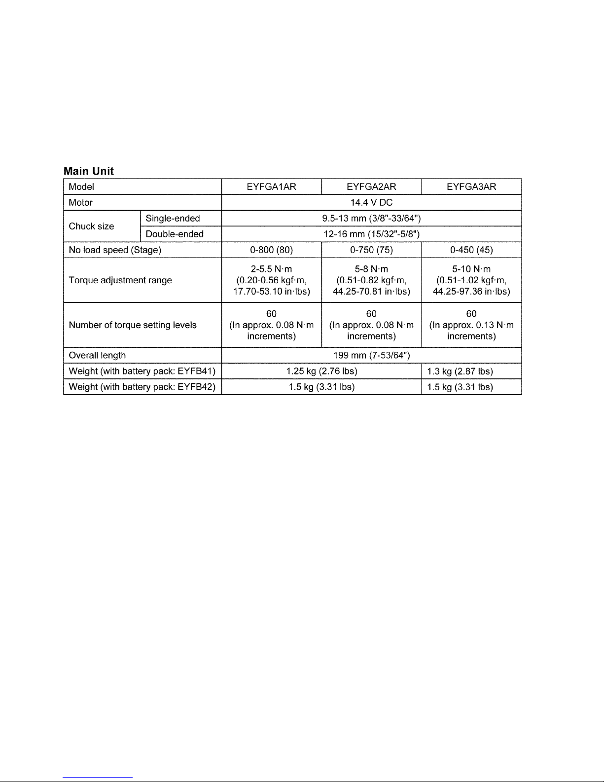
2 Specifications
3
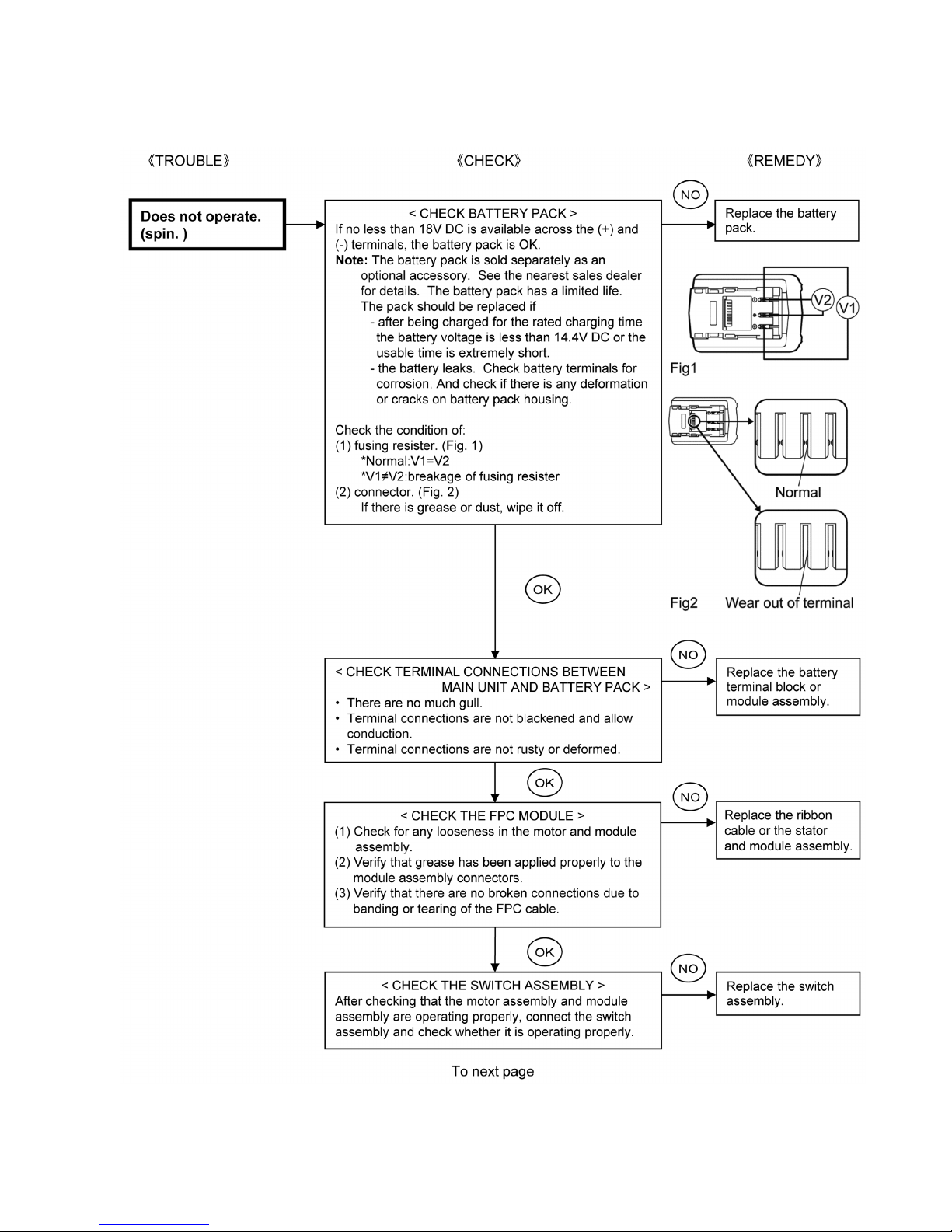
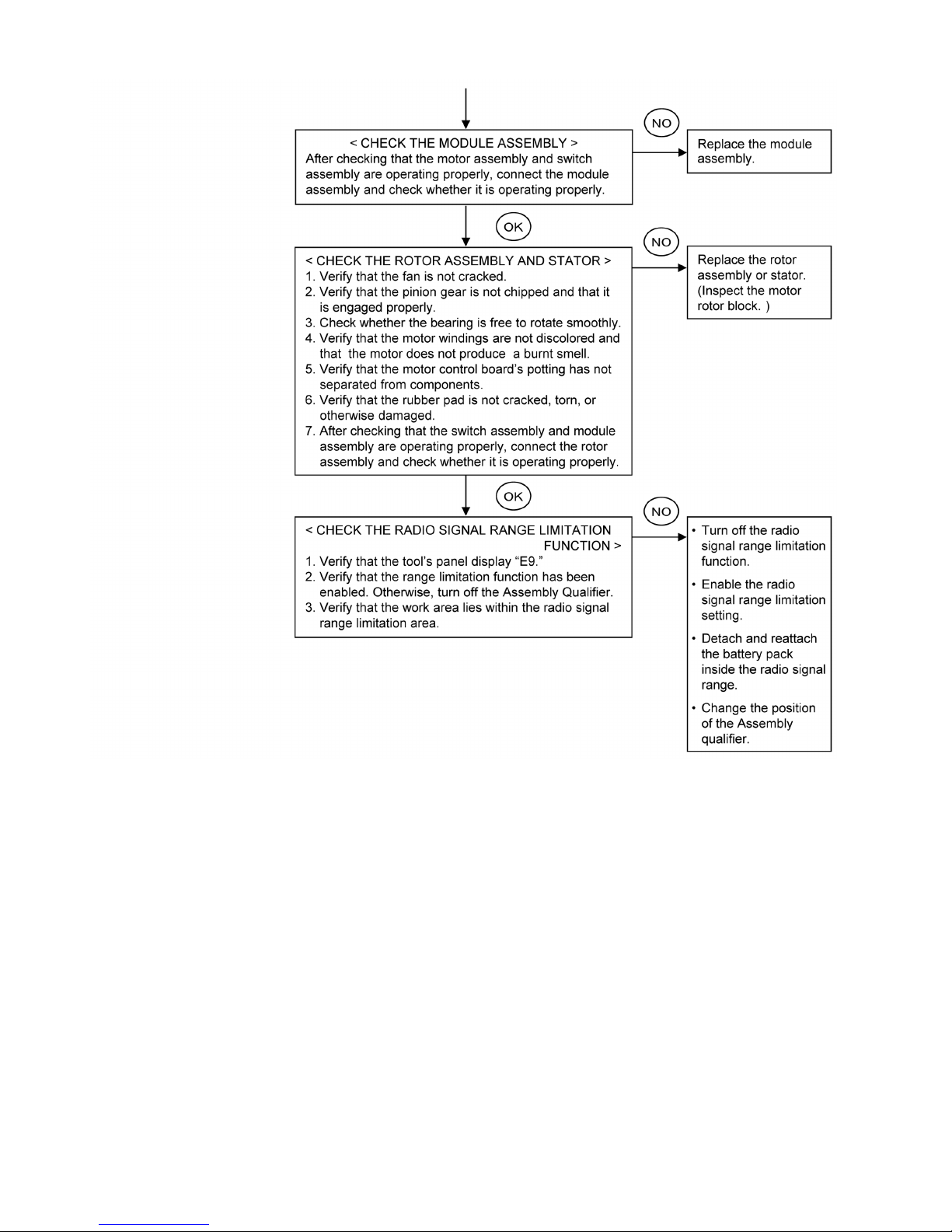
3 Troubleshooting Guide
3.1. Main unit and charging adaptor
4

5
3.2. Trial Operation (after checking Troubleshooting Guide)
3.2.1. Assembly
• Confirm if there is no gap between housing A and B by pinching lead wires.
• There is no dust or deformation on battery terminals.
3.2.2. Operation
• Check whether the tool operates properly in both the forward and reveres directions.
• Check whether the tool speed increases continuously as the trigger is gradually engaged.
• Set the LED light to switch-linked mode (L2) and check whether the LED light turns on when the trigger is engaged and that it
turns off when the trigger is released.
• Set the buzzer to each of its three modes and verify that there is no buzzer in b0 mode, that the buzzer sounds when the green
lamp is on in b1 mode, and that the buzzer sounds when the red lamp is on b2 mode.
• Check whether the ID setting has been properly configured after repair and reassembly.
• Check whether the clutch handle rotation switches smoothly from positions 1 through 60 (whether it makes a click sound).
• Confirmation of the radio communication.
6
7
• Check whether the LED light turns on and off each time the LED light on/off button is depressed.
3.2.3. Integrity
• With the switch activated, shake the tool back and forth and up and down and verify that its sound
• Check for the presence of any dirt or foreign matter from the repair process on the outside of the tool.
• Confirm if there is no metallic sound and abnormal sound when shaking up-down and right-left.
• Check whether the keyless chuck is attached securely to the tool.
8
4 Disassembly and Assembly Instructions
*To assemble the tool, start with 4.10 and proceed to 4.1
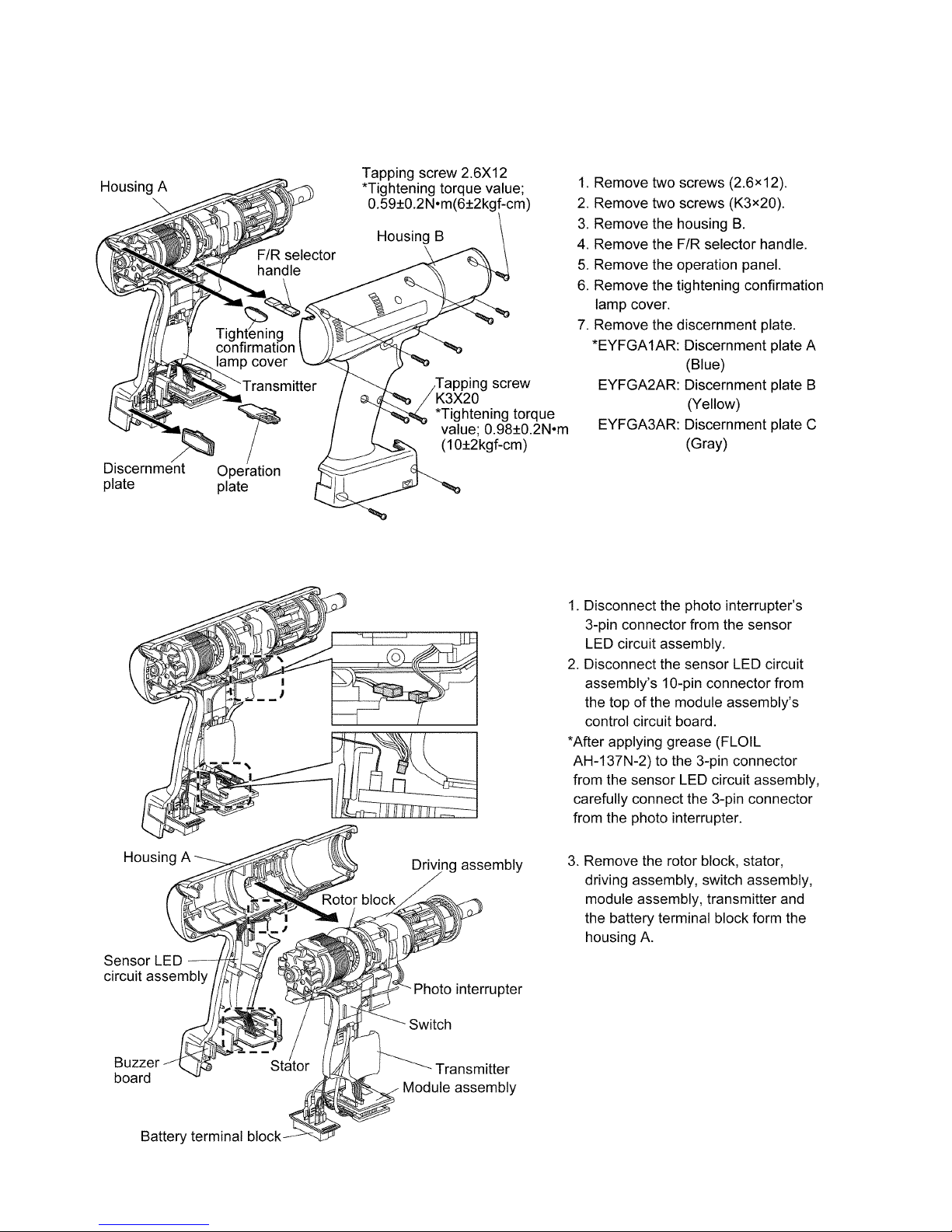
4.1. How to remove the housing B
4.2. How to remove assemblies
 Loading...