

Panasonic EX-21A Installation Manual
INSTRUCTION MANUAL
Ultra-compact Photoelectric Sensor
Amplifier Built-in Type
EX-20 Series
Thank you very much for using SUNX sensors.
Please read this Instruction Manual carefully and
thoroughly for the correct and optimum use of this
sensor. Kindly keep this manual in a convenient
place for quick reference.
This product is not a safety sensor. Its use
is not intended or designed to protect life
and prevent body injury or property damage
from dangerous parts of machinery. It is a
normal object detection sensor.
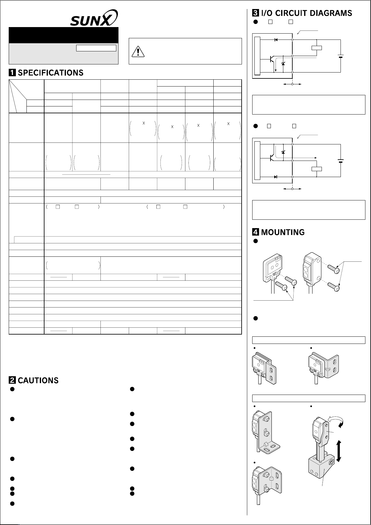
EX- A, EX- B, EX-23 / NPN output type
Color code
(Brown)+V
D
Tr
Sensor circuit
(Black) Output (Note)
D
Z
(Blue) 0V
50mA max.
Load
+
–
12 to 24V DC
±10%
Convergent reflective
Diffused beam type
EX-24A(-PN)
EX-24B(-PN)
2 to 25mm
(Conv. point: 10mm)
With 50 50mm
white non-glossy
paper
Min. ø0.1mm
copper wire
Setting
distance:
10mm
Small spot beam type
EX-26A(-PN)
EX-26B(-PN)
6 to 14mm
(Conv. point: 10mm)
With 50 50mm
white non-glossy paper,
spot diameter ø1mm with
setting distance 10mm.
Min. ø0.1mm
copper wire
Setting
distance:
10mm
15% or less of operation distance
0.1mm or less
(Setting distance: 10mm)
0.05mm or less
(Setting distance: 10mm)
20mA or less
Applied voltage: 30V DC or less(between output and +V)
Residual voltage: 1V or less(at 50mA source current)
0.4V or less(at 16mA source current)
Green LED
Continuously variable adjusterContinuously variable adjuster
20g approx.
Adjusting screwdriver: 1 No.
Model
(Note 1)
Item
No.
Type
Light-ON
Dark-ON
Thru-beam
Front sensing Front sensing
EX-21A(-PN)
EX-21B(-PN)
Side sensing Side sensing Side sensing Side sensing Side sensing
EX-23(-PN)
(Note 2)
Retroreflective
Diffuse reflective
EX-22A(-PN)EX-29A(-PN)
EX-22B(-PN)EX-29B(-PN)
5 to 160mm
Sensing range
1m 2m
30 to 200mm
(Note 3)
With 200 200mm
white non-glossy
paper
(Note 4)
Sensing object
Min. ø2.6mm
opaque object
Setting distance
between emitter and
receiver: 1m
Min. ø3mm
opaque object
Setting distance
between emitter and
ø15mm or more
opaque or
translucent object
receiver: 2m
(Note 3)
Opaque,
translucent or
transparent object
Hysteresis
Repeatability
(perpendicular to sensing axis)
Supply voltage
Current consumption
Output
Short-circuit protection
Response time
Operation indicator
Stability indicator
Sensitivity adjuster
Protection
Ambient temperature
Ambient humidity
Emitting element
Material
Cable
Weight
Accessories
)
Notes: 1
Model Nos. having the suffix ‘-PN’ are PNP output type.
The retroreflective type having the suffix ‘-Y’ at the end of the model No. does not have the reflector RF-200 enclosed with it.
)
Either Light-ON or Dark-ON can be selected by the operation mode switch (located on the receiver).
Notes: 2
)
The sensing range and the sensing object of the retroreflective type sensor are specified for the RF-200 reflector.
Notes: 3
Further, the sensing range is the possible setting range for the reflector. The sensor can detect an object less
than 30mm away. However, if the reflector is set 100mm or less away, the sensing object should be opaque.
)
In case of using this product at a sensing range of 50mm or less, take care that the sensitivity adjustment range
Notes: 4
becomes extremely narrow.
EX-24A(-PN) and EX-24B(-PN) are not
incorporated with a sensitivity adjuster. If
there is a reflective object (conveyor, etc.) in
the background, since it may affect the sensing,
use these models by keeping enough
distance from the reflective object.
If a reflective object is present in the
background, the sensing of EX-28A(-PN) and
EX-28B(-PN) may be affected. When setting
the sensor, make sure to confirm that the
reflective object has no effect. In case the
reflective object affects the sensing, take
measures such as removing the reflective
object or coloring it in black, etc.
If sensors are mounted close together and the
ambient temperature is near the maximum
rated value, provide for enough heat radiation/
ventilation.
Make sure to carry out the wiring in the power
supply off condition.
Take care that wrong wiring will damage the sensor.
Verify that the supply voltage variation is
within the rating.
If power is supplied from a commercial switching
0.05mm or less
0.3mm or less0.5mm or less
12 to 24V DC± 10% Ripple P-P 10% or less
Emitter: 10mA or less, Receiver: 15mA or less
EX- A, EX- B, EX-23
NPN open-collector transistor
• Maximum sink current: 50mA
•
Applied voltage: 30V DC or less(between output and 0V)
•
Residual voltage: 1V or less(at 50mA sink current)
0.4V or less(at 16mA sink current)
EX- A-PN, EX- B-PN, EX-23-PN
PNP open-collector transistor
• Maximum source current: 50mA
•
•
Incorporated
0.5ms or less
Orange LED(lights up when the output is ON)(thru-beam type: located on the receiver)
Green LED
lights up under stable light received
condition or stable dark condition
located on the receiver
Continuously variable adjuster,
located on the emitter
lights up under stable light received condition or stable dark condition)
(
IP67(IEC)
–25 to +55˚C(No dew condensation or icing allowed), Storage: –30 to +70˚C
35 to 85% RH, Storage: 35 to 85% RH
Red LED(modulated)
Enclosure: Polyethylene terephthalate, Lens: Polyalylate
2
0.1mm
3-core(thru-beam type sensor emitter: 2-core) cabtyre cable, 2m long
Emitter, receiver: 20g approx. each
Adjusting screwdriver: 1 No. Adjusting screwdriver: 1 No.
RF-200(Reflector): 1 No.
Adjusting screwdriver: 1 No.
In case noise generating equipment
(switching regulator, inverter motor, etc.) is
used in the vicinity of this product, connect the
frame ground (F.G.) terminal of the equipment
to an actual ground.
Do not use during the initial transient time
(50ms) after the power supply is switched on.
Extension up to total 50m (thru-beam type:
both emitter and receiver) is possible with
0.3mm2, or more, cable.
Make sure that stress is not applied directly to
the sensor cable joint.
Do not run the wires together with highvoltage lines or power lines or put them in the
same raceway. This can cause malfunction
due to induction.
Take care that the sensor is not directly
exposed to fluorescent light from a rapid-starter
lamp or a high frequency lighting device, as it
may affect the sensing performance.
Avoid dust, dirt and steam.
Take care that the sensor does not come in
direct contact with water, oil, grease, or
organic solvents, such as, thinner, etc.
regulator, ensure that the frame ground (F.G) terminal
of the power supply is connected to an actual ground.
Narrow-view reflective
Long distance spot beam type
EX-28A(-PN)
EX-28B(-PN)
Internal circuit
Note: The emitter of thru-beam type sensor does not incorporate the output.
Symbols . . . D
Symbols . . . ZD
Symbols . . . Tr
45 to 115mm
With 100 100mm
white non-glossy paper,
spot diameter ø5mm with
setting distance 80mm.
Opaque,
translucent or
transparent object
Min. ø1mm
copper wire wich
setting distance 80mm
0.3mm or less
EX- A-PN, EX- B-PN, EX-23-PN / PNP output type
Tr
Sensor circuit
Internal circuit
Note: The emitter of thru-beam type sensor does not incorporate the output.
Symbols . . . D
Symbols . . . ZD
Symbols . . . Tr
Mount using M3 screws. The tightening torque
should be 0.5N·m or less.
M3 pan head screws (Note)
When mounting the front sensing type sensor, use
Note:
M3 pan head screws without washers, etc.
Sensor mounting brackets (optional) are available. In
case the sensor is mounted on a sensor mounting
bracket the tightening torque should be 0.5N·m or less.
Sensor mounting bracket for front sensing type
MS-EX20-1 MS-EX20-3
Sensor mounting bracket for side sensing type
MS-EX20-2
MS-EX20-4
Material: Stainless steel (SUS304)
Two M3 (length 14mm)
screws with washers
[stainless steel (SUS304)]
are attached.
Users’ circuit
:
Reverse supply polarity protection diode
: Surge absorption zener diode
: NPN output transistor
Color code
(Brown)+V
ZD
50mA max.
(Black) Output (Note)
D
(Blue) 0V
:
Reverse supply polarity protection diode
Load
Users’ circuit
+
–
: Surge absorption zener diode
: PNP output transistor
Material: Stainless steel
(SUS304)
Two M3 (length 5mm)
pan head screws
[stainless steel (SUS304)]
are attached.
Material: Stainless steel (SUS304)
Two M3 (length 5mm) pan head screws
[stainless steel (SUS304)] are attached.
MS-EX20-5
[For EX-23 (-PN)]
Material: Stainless steel
(SUS304)
Two M3 (length 14mm)
screws with washers
[stainless steel (SUS304)]
are attached.
Material: Nylon 6
Two M3 (length 12mm) screws with washers
[stainless steel (SUS304)],
one M3 (length10mm) hexagon-socket-head bolt
[stainless steel (SUS304)], and
one M3 hexagon nut [stainless (SUS304)] are
attached.
Material:
Die-cast zinc alloy
12 to 24V DC
±10%
M3 screws
Swivel:
360° rotation
Height adjustment:
15mm approx.
Parts description
EX-21
Stability indicator (Green)(Note)
Lights up under stable light received
condition or stable dark
condition.
Beam axis
Operation indicator (Orange)(Note)
Lights up when the output is ON.
Note: Not incorporated on the emitter.
EX-23
Stability indicator (Green)(Note)
Lights up under stable light received
condition or stable dark
condition.
Beam axis
Operation indicator (Orange)(Note)
Lights up when the output is ON.
Operation mode switch
(located on the receiver)
L
: Light-ON
L
D
: Dark-ON
Sensitivity adjuster
D
(located on the emitter)
Sensing range increases
when turned clockwise.
Note: Not incorporated on the emitter.
EX-24
Stability indicator (Green)
Lights up under stable light received
condition or stable dark
condition.
Beam-receiving part
Operation indicator (Orange)
Lights up when the output is ON.
Beam-emitting part
EX-22 /26 /28 /29
Stability indicator (Green)
Lights up under stable light received
condition or stable dark condition.
Beam-receiving part
Beam-emitting part
Operation indicator (Orange)
Lights up when the output is ON.
MAX
Sensitivity adjuster
Sensing range increases
when turned clockwise.
Operation mode switch [EX-23 (-PN) only]
Switch position Description
L
Light-ON mode is obtained when the
operation mode switch (located on the
receiver) is turned fully clockwise (L side).
D
L
Dark-ON mode is obtained when the operation mode switch (located on the receiver)
is turned fully counterclockwise (D side).
D
Note: Operation mode switch should be turned fully till it stops.
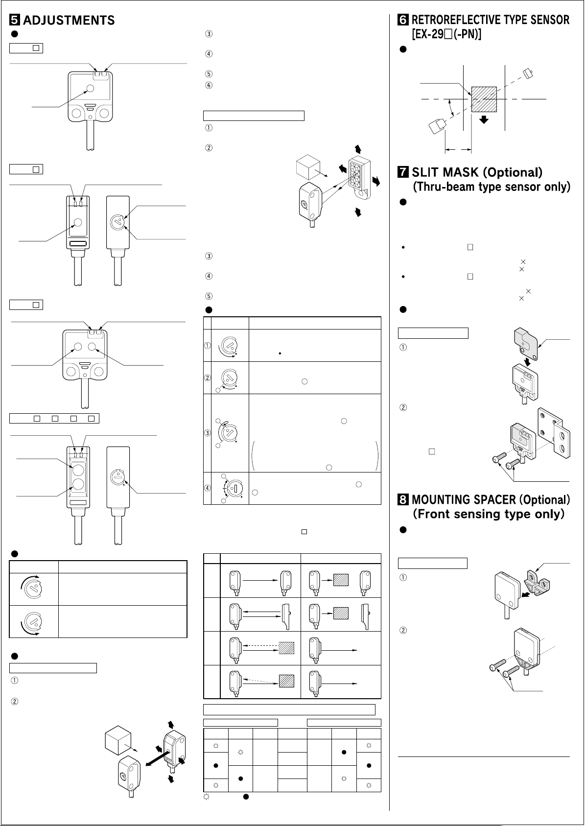
Light beam alignment
Thru-beam type sensor
In case of EX-23(-PN), set the operation mode
switch to the Light-ON mode position (L side).
Placing the emitter and the receiver face to face
along a straight line, move the emitter in the up,
down, left and right
directions, in order to
determine the range
Sensing object
Emitter
of the light received
condition with the help
of the operation indicator. Then, set the
emitter at the center
of this range.
L
D
Receiver
Similarly, adjust for up, down, left and right
angular movement of the emitter.
Further, perform the angular adjustment for the
receiver also.
Check that the stability indicator lights up.
In case of EX-23 (-PN), choose the operation
mode, Light-ON or Dark-ON, as per your
requirement, with the operation mode switch.
Retroreflective type sensor
Turn the sensitivity adjuster fully clockwise to
the maximum sensitivity position (MAX).
Placing the sensor
and the reflector
Sensing object
face to face along a
straight line, move
the reflector in the
up, down, left and
right directions, in
order to determine
the range of the light
received condition
M
A
X
Sensor
Reflector
with the help of the operation indicator. Then,
set the reflector at the center of this range.
Similarly, adjust for up, down, left and right
angular movement of the reflector.
Further, perform the angular adjustment for the
sensor also.
Check that the stability indicator lights up.
Sensitivity adjustment (Side sensing type only)
Sensitivity adjuster
Step
MAX
Turn the sensitivity adjuster fully counterclockwise to the minimum sensitivity
position ( mark).
In the light received condition, turn the
MAX
sensitivity adjuster slowly clockwise and
confirm the point where the sensor enters
A
B
A
Optimum position
Notes: 1)
Type
Thru-beam
Retroreflective
Diffuse reflective
Convergent reflective
Narrow-view reflective
the ‘Light’ state operation.
In the dark condition, turn the sensitivity
adjuster further clockwise until the sensor
enters the ‘Light’ state operation and then
bring it back to confirm point where the
MAX
sensor just returns to the ‘Dark’ state
operation.
If the sensor does not enter the ‘LIght’
state operation even when the sensitivity
adjuster is turned fully clockwise, this
B
A
2)
extreme position is point .
MAX
The position at the middle of points and
B
is the optimum sensing position.
Use the accessory adjusting screwdriver to turn
the adjuster slowly. Turning with excessive
strength will damage the adjuster.
In case of using EX-22 (-PN) at a sensing range
of 50mm or less, take care that the sensitivity
adjustment range becomes extremely narrow.
Light received condition Dark condition
Sensor
Sensor
Sensor Sensor
Description
A
B
B
A
Receiver ReceiverEmitter Emitter
Sensing object
Emitter
Reflector Reflector
Sensing object
Sensor
Sensing object
Sensing object
Relation between sensing output and indicators
In case of Light-ON
Stability
Operation
indicator
Output Output
indicator
OFF ON
ON
: lights up : lights off
Sensing
condition
Stable light
receiving
Unstable light
receiving
Unstable dark
condition
Stable dark
condition
In case of Dark-ON
Operation
indicator
OFF
Stability
indicator
When sensing a glossy object, mount the
sensor at an angle to the object surface.
Glossy surface
10 to 30°
Sensor
Sensing object
L Make L sufficiently long
Reflector
Apply a slit mask when detecting small
objects or for increasing the accuracy of
sensing position.
However, the sensing range is reduced when
the slit mask is mounted.
Slit mask for
Slit mask for
EX-21
EX-23
OS-EX20-05
(
Slit size ø0.5mm)
OS-EX20-05 3
(
Slit size 0.5 3mm)
OS-EX20E-05
(
Slit size ø0.5mm)
OS-EX20E-05 3
(
Slit size 0.5 3mm)
The slit mask should be mounted on the
sensor before mounting the sensor.
Mounting method
Put the slit mask on
Slit mask
(Optional)
the sensor as shown
in the right figure.
Align the mounting
holes of the slit mask
and the sensor and
mount with two M3
screws [in case of
EX-
21 (-PN), M3 pan
head screws].
The
tightening torque should
be 0.5N·m or less.
M3 pan head screws
When mounting the front sensing type from
the backside, fit the mounting spacer
(MS-EX20-FS) and fix with screws.
Mounting method
Mounting
spacer
(Optional)
Fit the mounting
spacer on the sensor.
Align the mounting holes
of the mounting spacer
and the sensor and
mount with M3 screws.
The tightening torque
should be 0.5N·m or
less.
M3 screws
http://www.sunx.co.jp/ SUNX Limited
SUNX Limited
2431-1 Ushiyama-cho, Kasugai-shi, Aichi, 486-0901, Japan
Phone: +81-(0)568-33-7211 FAX: +81-(0)568-33-2631
Overseas Sales Dept.
Phone: +81-(0)568-33-7861 FAX: +81-(0)568-33-8591
PRINTED IN JAPAN
 Loading...