

Hall ICs
DN8799MS
3 V operation Hall IC
■ Overview
The DN8799MS is a 3 V operation Hall IC which
includes a Hall element, amplifier circuit, Schmidt circuit,
stabilized power supply and temperature compensation
circuit which are integrated on a single chip with a fine
patterning technology. The magnetic input signal is outputted by being converted to high or low. We have improved the conventional circuit to realize a stable operation covering from low to high supply voltage and from
low to high temperature.
■ Features
• Wide operating supply voltage range
(V
= 2.7 V to 14.4 V)
CC
• Wide operating ambient temperature (−40°C to +85°C)
• Package: Mini type (3-pin type)
(1.1 mm thick: Same as a standard transistor)
■ Applications
• Cellular phone (detection of cover open/close), position sensor
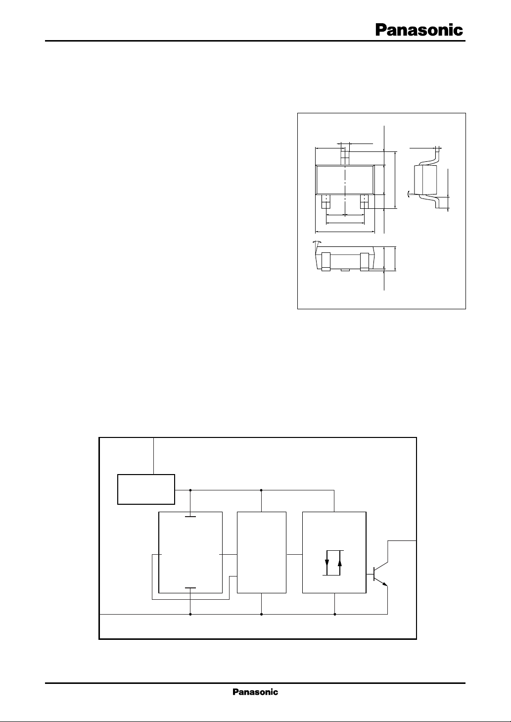
■ Block Diagram
10°
1.45
1
0.95
1.90
2.90
± 0.20
+ 0.20
– 0.05
0.40
3
2
0.95
± 0.15
+ 0.10
– 0.05
0.65
– 0.05
+ 0.25
1.50
± 0.15
0.65
– 0.10
+ 0.20
1.10
0 to 0.1
MINI-3D
+ 0.20
2.80
– 0.30
+ 0.30
1.10
– 0.10
0.16
5°
Unit: mm
+ 0.10
– 0.06
± 0.20
0.40
GND
Constant
voltage source
3
CC
V
2
Hall element Amplifier
Comparator
1
Out
1
DN8799MS Hall ICs
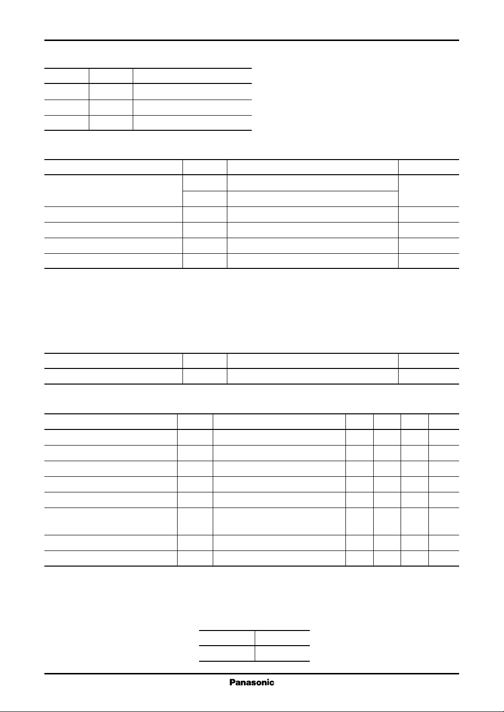
■ Pin Descriptions
Pin No. Symbol Description
1 Out Output pin
2VCCSupply voltage pin
3 GND Ground pin
■ Absolute Maximum Ratings
Parameter Symbol Rating Unit
Supply voltage V
Supply current I
Power dissipation P
Operating ambient temperature T
Storage temperature T
Note) 1. Except for the operating ambient temperature and storage temperature, all ratings are for Ta = 25°C.
2. The reverse insertion of this IC will cause its breakdown.
3. It will operate normally in several tens of ms after power on.
4. This IC is designed for a general use and if you want to use for an automotive use, please consult our staff of the nearby
sales office beforehand.
CC
V
OUT
CC
D
opr
stg
18 V
18
mA
120 mW
−40 to +85 °C
−55 to +125 °C
■ Recommended Operating Range
Parameter Symbol Range Unit
Supply voltage V
CC
2.7 to 14.4 V
■ Electrical Characteristics at Ta = 25°C
Parameter Symbol Conditions Min Typ Max Unit
1
Operating magnetic flux density 1
Operating magnetic flux density 2 BL-H VCC = 3 V −3mT
Hysteresis width BW VCC = 3 V 0.2 1.5 4.0 mT
Output voltage 1 V
Output voltage 2 V
Output current I
Supply current 1 I
Supply current 2 I
Note) 1. Symbol BH-L stands for the operating magnetic flux density where its output level varies from high to low.
2. Symbol BL-H stands for the operating magnetic flux density where its output level varies from low to high.
3. The variation of operating magnetic flux density does not depend on supply voltage due to its built-in stabilized power
source. (VCC should be confined to the range of 2.7 V to 14.4 V.)
4. A supply current changes by maximum 1 mA when its output level varies from high to low.
5.*1: Classified by BH-L as listed right:
*
BH-L VCC = 3 V −20 mT
VCC = 14.4 V, IO = 5 mA, B = −20 mT 0.07 0.30 V
OL1
VCC = 2.7 V, IO = 5 mA, B = −20 mT 0.07 0.30 V
OL2
VCC = 2.7 V to 14.4 V 10 µA
OH
VO = 14.4 V, B = −3 mT
VCC = 14.4 V, B = −3 mT 1.0 3.4 6.0 mA
CC1
VCC = 2.7 V, B = −3 mT 1.0 2.5 6.0 mA
CC2
Rank A
BH-L (mT) ≥ −15
2
 Loading...