

Panasonic DN8695 Datasheet
■ Overview
The DN8695 is a 9-circuit non-inverting type driver array com-
posed of TTL circuit and 1.5A NPN Darlington transistors.
■ Features
• 9 circuits
• High breakdown voltage : V
CE(SUS)
=50V (min)
• Large output current : I
O
=1.5A (max)
• Low active input
• TTL compatible input
■ Applications
• Driving of the printer motors, etc.
• Driving of the LEDs, lamps, and various relays
DN8695
9-circuit Darlington Driver Array (High Breakdown Voltage : 50V,
Large Drive Current : 1.5A)
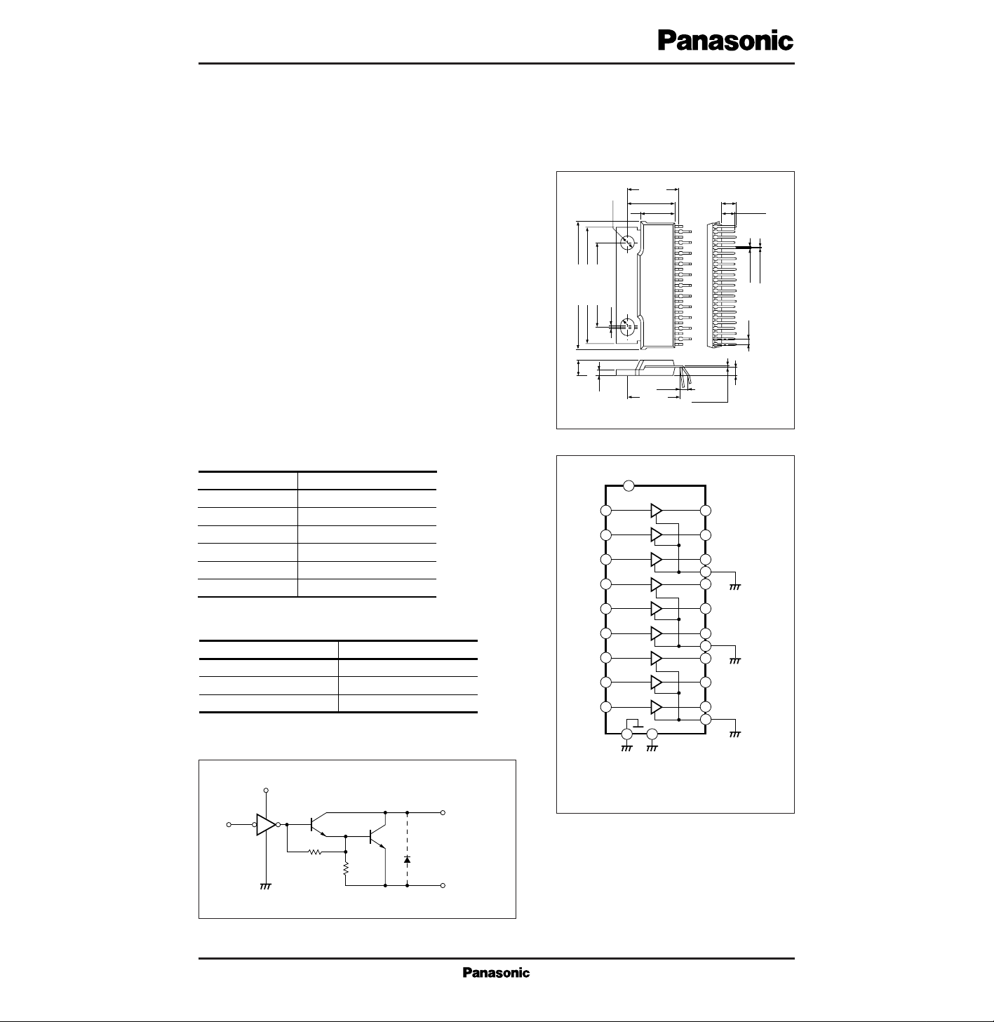
23-pin ZIP Plastic Package with Fin (HZIP023-P-0138)
(12.33)
11.3±0.25
4.5min
3.7min
8.2±0.3
20.0±0.2
ø3.6
123
28.0±0.3
3.5±0.3
29.96±0.3
0.6
R18
Unit : mm
1.27
0.6±0.1
0.3±0.1
1.2±0.15
1.8±0.25
(12.33)
(2.2)
0.25
+0.1
– 0.05
■ Schematic Circuit (1 Circuit)
7
5
9
11
15
13
17
21
1
3
8
10
4
6
16
18
23
20
19
22
12
14
2
V
CC
I
3
I
4
I
1
I
2
I
7
I
8
I
9
I
5
I
6
Q
3
P-GND
1
Q
1
Q
2
Q
7
Q
8
Q
9
Q
5
Q
4
Q
6
P-GND
2
P-GND
3
Fin
GND
Note) GND, Fin, P-GND 1, 2, and 3 are
connected inside the IC, but be sure
to connect them outside for use.
■ Block diagram
Input (In) Output (Qn)
■ Function Table
L
H
OPEN
L
H
H
Symbol Pin name
■ Pin Descriptions
Q1 to Q
9
P-GND1 to P-GND
3
I1 to I
9
GND
V
CC
Fin
Output pin
Driver ground pin
Input pin
Ground pin
Power pin
Fin
I
V
CC
P-GND
Q
1
R
Q
2
R
Q
GND
V
CC
V
CE (sus)
I
O
V
I
P
D
T
opr
T
stg
Supply voltage
Output breakdown
Output current
Input voltage
Power dissipation
Operating ambient temperature
Storage temperature
V
V
A
V
W
˚C
˚C
7
50
1.5
0 to V
CC
20
*
–20 to +75
–55 to +150
*
Ta=75˚C when the infinite heat sink is used
Parameter Symbol Rating Unit
■ Absolute Maximum Ratings (Ta=25˚C)
Input voltage
V
IH
V
V
CC
=4 to 6V
V
IL
V
V
CC
=4 to 6V
Output saturation voltage
V
CE (sat)
2.2 V
V
CC
=4V, VI=0.8V, IO=1A
Input current
I
IH
µA
V
I
=2.4V
I
IL
µA
V
I
=0V
mA
V
C
=6V, VCE=50V, VI=2V
Output leakage current
I
OLK
mA
V
CC
=5V, Total VI=2.4V
Supply current
I
CCH
mA
V
CC
=5V, Total VI=0V
I
CCL
V
Output suspending voltage
V
CE (sus)
µs
L=4mH, R=40Ω, I
O
=600mA
Propagation delay time
t
PHL
µs
V
H
=60V, RL=45Ω
5
5
50
10
0.8
10
1
45
50
2
–10
–100
t
PLH
VCC=5V, CL=15pF
Parameter Symbol Condition min typ max Unit
■ Electrical Characteristics (VCC=5V, Ta=25˚C)
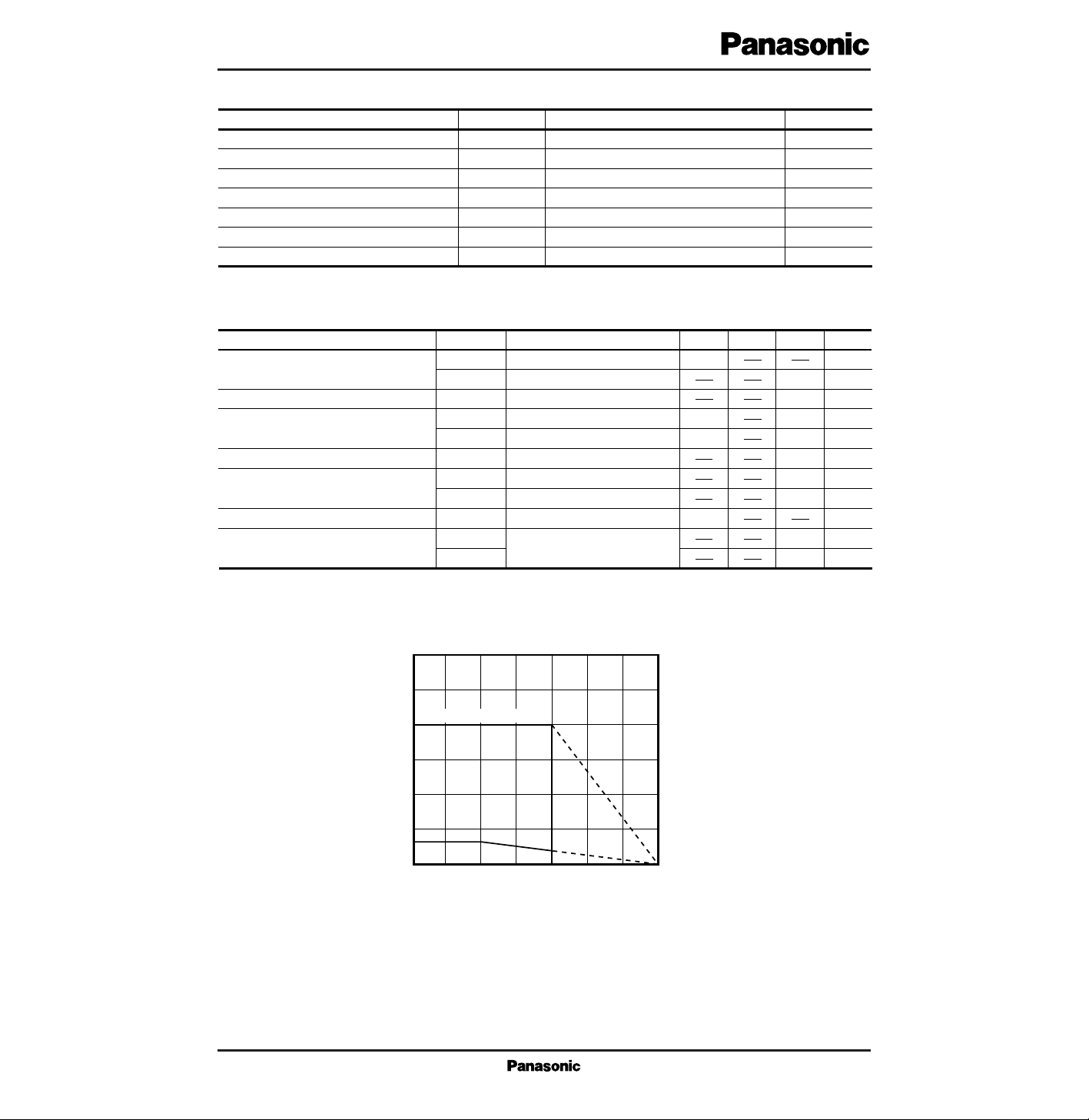
30
25
20
15
10
5
–20 0 25 50 75 100 125 150
When Infinite Heat Sink is used
Ambient Temperature Ta (˚C)
Power Dissipation P
D
(W)
PD – Ta
■ Characteristics Curve
 Loading...