

Panasonic DN6849UBS Datasheet
Hall ICs
DN6849UBS
Hall IC for alternative magnetic field
■ Overview
The DN6849UBS is a Hall IC in which a Hall element,
an amplifier circuit, Schmidt circuit, stabilized power supply and temperature compensation circuit are integrated
onto a single chip using IC technology. It amplifies Hall
element output in the amplifier, converts it into a digital
signal through the Schmidt circuit so as to drive the TTL
or MOS IC directly.
■ Features
• High sensitivity and low drift
• Stable temperature characteristics due to the built-in tem-
perature compensation circuit
• Wide operating supply voltage range
(V
= 4.5 V to 16 V)
CC
• Operating in alternative magnetic field
• Open collector output
■ Applications
• Speed sensor, position sensor, rotation sensor and key board switch
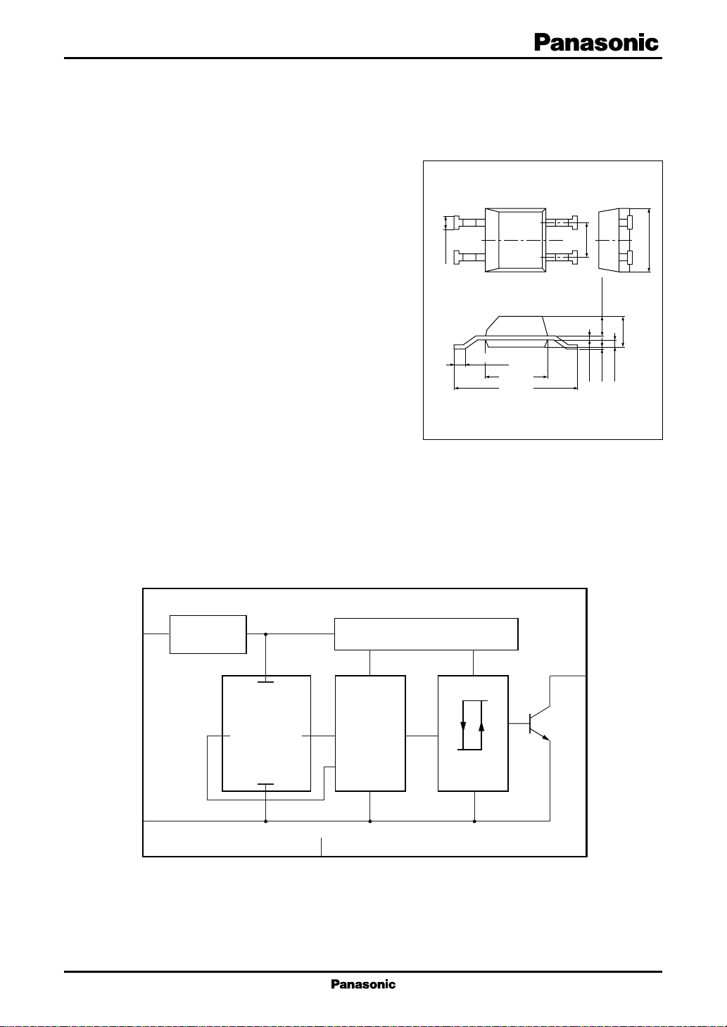
■ Block Diagram
0.6±0.2
1
2
0.4±0.15
4
3
3.0±0.3
5.4±0.4
ESOP004-P-0200
Unit: mm
1.6
0.95±0.2
+0.15
–0.05
0.2
0.1±0.1
3.0±0.3
1.5±0.3
0.4±0.2
V
CC
GND
1
Stabilized
power supply
4
Temperature compensation circuit
Hall element Amplifier
2
N.C.
Schmidt circuit
Output
stage
3
Out
1
DN6849UBS Hall ICs
■ Pin Descriptions
Pin No. Description
1 Supply voltage pin
2N.C.
3 Output pin
4 Ground pin
■ Absolute Maximum Ratings
Parameter Symbol Rating Unit
Supply voltage V
Supply current I
2
Power dissipation
Operating ambient temperature
Storage temperature
Note) 1. The reverse insertion of this IC will cause its breakdown.
2. It will operate normally in several tens of ms after power on.
3. Use it within 100 mT of magnetic flux density, because if 100 mT or more is applied, the output of Hall IC is likely to be
inverted.
4. Since this IC requires a special assembly, its anti-moisture characteristic is poor compared with other ordinary ICs.
If high reliability is required, you should dry PCB well after mounting and mold them with resin over the PCB.
5.*1: Except for the operating ambient temperature and storage temperature, all ratings are for Ta = 25°C.
2: Shows the allowable power consumption at Ta = 100°C.
*
*
1
*
1
*
If the operation condition exceeds 62.5 mW, take measure in mounting and etc.
CC
CC
P
D
T
opr
T
stg
− 0.3 to +18 V
8mA
62.5 mW
−40 to +100 °C
−55 to +125 °C
■ Recommended Operating Range
Parameter Symbol Range Unit
Supply voltage V
2
CC
4.5 to 16 V
 Loading...