

Panasonic DMR-ES20DEB User Manual

Operating Instructions
DVD Recorder
Model No. DMR-ES20DEB
Panasonic
This DVD Recorder is for viewing and recording free to view channels only, not pay TV or encrypted channels.
DVD RECORDER DMR-ES20D
DVD RECORDING
DVD-RAM / DVD-R / DVD-RW / +R
OPEN/CLOSE
/x1.3
Sales and Support Information
Direct Sales at Panasonic UK
î Order accessory and consumable items for your product with ease and confidence by phoning
our Customer Care Centre
Monday - Thursday 9:00am - 5:30pm, Friday 9:30am - 5:30pm (Excluding public holidays).
î Or go online through our Internet Accessory ordering application at www.panasonic.co.uk
î Most major credit and debit cards accepted.
î All enquiries, transactions and distribution facilities are provided directly by Panasonic UK Ltd.
î It couldn´t be simpler!
î Also available through our internet is direct shopping for a wide range of finished products,
take a browse on our website for further details.
REC
Customer Care Centre
î For customers within the UK: 08705 357357
î Visit our website for product information: www.panasonic.co.uk
î E-mail: customer.care@panasonic.co.uk
Before connecting, operating or adjusting this product, please read the instructions completely.
Please keep this manual for future reference.

Table of Contents
Page
Page Page
Important Safety Warnings / Caution
Before You Start 4-5
Included Accessories 4
Product Introduction 5
Single-frame playback
3
Quick View 23
Splitting a recording into chapters 24
Manual Skip 24
TIME SLIP 24
Remote control 6-7
Front Panel 8
Rear Panel 8
Delayed playback 24
MP3 playback 25
JPEG playback 26
Display 9
14
14
15
Recording
Recording television programmes 27
Pause during recording 27
One touch recording
(OTR)
Direct TV recording
Playback during recording
Simultaneous recording and playback
Recording modes and approximate
recording times in hours 28
Selecting an audio channel to be
recorded in two-channel sound 28
FLEXIBLE REC 28
Displaying the available recording time 28
21-pin Scart Socket 9
Connecting with a 21-pin Scart cable 10
Setup with Q Link 11
Setup without Q Link 11
Connecting with Audio/Video cable 12
Connecting with S Video cable 12
Connecting to Satellite Receiver 13
Connecting with RF cable (Aerial cable)
Auto-Setup with RF cable
(Aerial cable)
Removing Interference / Changing RF
output channel
Checking the Settings after Auto-Setup 15
COMPONENT VIDEO OUT 16
External devices 17
TIMER controlled recordings
TV Guide 18-19
Handling Discs 20
Disc formats 20-21
Options in the TIMER RECORDING menu 28
Manual programming
29
TIMER RECORDING in the TV Guide 30
TIMER RECORDING from
analogue channels 30
Programming recordings
Playback
Playback, PAUSE during playback 22
Cancelling playback 22
Resuming playback 22
A menu appears on the television screen
Direct playback
22
22
with VIDEO Plus+
31
TIMER recording from Sat
with VIDEO Plus+
31
TIMER recordings via external devices
Recording from an external device,
e.g. a camera 32
Selecting programmes/
titles for playback
FUNCTIONS Selection Menu
23
Slow-motion playback, FUNCTIONS Selection Menu 33
Fast forward/rewind 23 Symbols in the TIMER RECORDING menu 34
Skipping chapters, titles or pictures 23 Symbols in the DIRECT NAVIGATOR 34
Entering Text 34
23
DIRECT NAVIGATOR
Editing
Chapter View 37
PLAYLISTS
Creating a Playlist
Select/Edit Playlists
Edit Chapter 40
SETUP 41
Tuning 41-44
Disc 44
27
27
27
27
Language codes 44
Picture 45
Sound 45
Display 46
Connection 46
Others 47-48
DISC MAGEMENT
Disc Name, Disc Protection,
Erase all titles 49
Format Disc 49
Auto-Play Select, Finalize 50
STATUS displays 51-52
Informations 51
DISPLAY menus 53
Before requesting service 54-55
Specifications last page
32
Index last page
35-36
38
38-39
If you see this symbol
Information on disposal for users of waste electrical & electronic equipment (private households)
This symbol on the products and/or accompanying documents means that used electrical and electronic products
should not be mixed with general household waste. For proper treatment, recovery and recycling, please take
these products to designated collection points, where they will be accepted on a free of charge basis. Alternatively,
in some countries you may be able to return your products to your local retailer upon the purchase of an
equivalent new product. Disposing of this product correctly will help to save valuable resources and prevent any
potential negative effects on human health and the environment which could otherwise arise from inappropriate
waste handling. Please contact your local authority for further details of your nearest designated collection point.
Penalties may be applicable for incorrect disposal of this waste, in accordance with national legislation.
For business users in the European Union
If you wish to discard electrical and electronic equipment, please contact your dealer or supplier for further information.
Information on disposal in other countries outside the European Union
This symbol is only valid in the European Union. If you wish to discard this product, please contact your local authorities
or dealer and ask for the correct method of disposal.
2
Safety Precautions
Important Safety Warnings
!
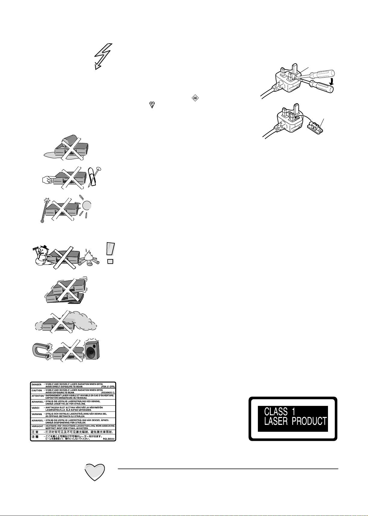
The moulded three pin mains plug is supplied for your safety and convenience
and must NOT be cut off.
!
A 5 amp fuse is fitted in the mains
plug. If the fuse has to be replaced,
it must be of the same rating and
1.Open the fuse
cover with a
screwdriver.
approved by ASTA or BSI to BS1362.
Check for the ASTA mark or the
BSI mark on the body of the fuse.
To replace the fuse, open the fuse
compartment with a screwdriver as
shown and replace the fuse and the
cover securely.
!
To prevent electric shock, do not remove cover. No user serviceable parts inside.
2.Replace the
fuse and close
or attach the
fuse cover.
Refer servicing to qualified service engineer only.
!
WARNING: To reduce the risk of fire, electric shock or product damage, do not
expose this apparatus to rain, moisture, dripping or splashing and that no
objects filled with liquids, such as vases, shall be placed on the apparatus.
!
Do not insert metal object into the slots or openings of the unit.
!
This unit is not disconnected from a.c. mains while it remains connected
to a live mains outlet, even if it has been turned off.
!
The socket outlet shall be installed near the equipment and easily accessible or
the mains plug or an appliance coupler shall remain readily operable.
!
This unit is intended for use in moderate climates.
Fuse cover
Fuse
(5 ampere)
Inside of product
Caution
!
Avoid exposing the unit to direct sunlight or other heat sources.
!
Avoid sudden change in temperature or humidity, dew or condensation may
form, causing malfunction.
!
Dispose of batteries in accordance with the instructions given in this book.
!
Place the unit on a flat, stable surface. Do not place heavy object on top of the unit.
!
Your attention is drawn to the fact that recording of pre-recorded tapes or discs
or other published or broadcast materials may infringe copyright laws.
!
This unit is designed for indoor use only.
!
Do not use in area with strong magnetic fields, e.g. near transmitting antenna.
!
This product may receive radio interference caused by mobile telephones during
use. If such interference is apparent, please increase separation between the
product and the mobile telephone.
!
Do not install or place this unit in a bookcase, built-in cabinet or in another
confined space. Ensure the unit is well ventilated. To prevent risk of electric
shock or fire hazard due to overheating, ensure that curtains and any other
materials do not obstruct the ventilation vents.
!
Do not obstruct the unit’s ventilation openings with newspapers, tablecloths,
curtains, and similar items.
!
Do not place sources of naked flames, such as lighted candles, on the unit.
!
Dispose of batteries in an environmentally friendly manner.
!
This product utilizes a laser. Use of controls
or adjustments or performance of procedures
other than those specified herein may result
in hazardous radiation exposure. Do not
open covers and do not repair yourself.
Refer servicing to qualified personnel.
Back of product, see page 8
Care and Maintenance
!
The cabinet can be wiped clean with a damp cloth, disconnect from mains before
cleaning. Do not use detergent or solution containing benzol or petroleum.
3
Before You Start
Dear customer
Thank you for your trust and your decision to purchase this top-quality device.
Panasonic is one of the leading manufacturers of entertainment electronics devices.
We are sure that you will be completely satisfied with this device.
With the new Quick Start feature, the unit is ready for use within approx. 1 second.
Thus, if a DVD-RAM was previously inserted, recording can begin immediately after
the unit is switched on from Standby mode.
Matsushita Electric Industrial Co., Ltd.
http://www.panasonic.co.jp/global/
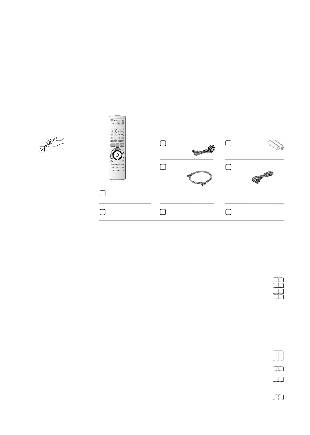
Check that you have the
accessories and items shown
DVD
TV
DIRECT TV REC
AV
1
2
4
5
8
7
INPUT SELECT
CANCEL
0
*
SKIP
PAUSE
STOP
T
X
E
T
R
ENTER
O
T
T
A
C
G
I
E
V
R
I
A
D
N
SUB MENU
S
MANUAL SKIP
REC
REC MODE
TIME SLIP
STATUS
Panasonic
A
DVD/TV
EUR7729KK0
Remote control
Included
VOLUME
CH
ccessories
PAGE
3
CH
6
VIDEO Plus+
9
DISPLAY
SLOW/SEARCH
PLAY/x1.3
F
U
N
C
T
I
O
N
S
RETURN
CREATE
CHAPTER
ERASE
EXT LINK
TIMER
PROG
STTL
CHECK
AC Mains Lead
RJA0044-3C
RF Cable
K1TWACC00001
Batteries for the
Remote Control
R6 size
Audio / Video Cable
K2KA6CA00001
EUR7729KK0
Guarantee Card
Quick Start Guide
Operating Instructions
Preparation
1. Read the operating instructions, the safety precautions and the information on setting
up the unit on page 3 thoroughly before you connect, operate or adjust any settings
on the unit.
2. Insert the batteries into the remote control.
3. Connect the device to your television.
Connecting with 21-pin Scart cable
Connecting with RF cable
(Aerial cable)
Connecting with Audio/Video cable
Connecting with S VIDEO cable
4. The automatic settings start after the unit is switched on.
The station settings of all receivable television stations are automatically transferred to
the DVD Recorder. The Auto-Setup begins with download of the digital data afterwards
starts the download of analogue data.
With Q Link function and 21-pin Scart socket:
First Auto-Setup begins with download of the digital data. Then during
[Download from
TV], the station settings of all receivable analogue television stations are automatically
transferred from your television set to the DVD Recorder.
Connecting with 21-pin Scart cable:
Setup with Q Link
Setup without Q Link (Automatic Tuning)
Connecting with RF cable :
Auto-Setup with RF cable (Automatic Tuning)
(Aerial cable)
(Aerial cable)
Connecting with Audio/Video cable / S VIDEO cable:
Setup without Q Link (Automatic Tuning)
10
14
12
12
14
11
11
11
5. The basic settings of the unit are complete.
You can change the basic settings in the menu.SETUP
41- 48
4
Before You Start
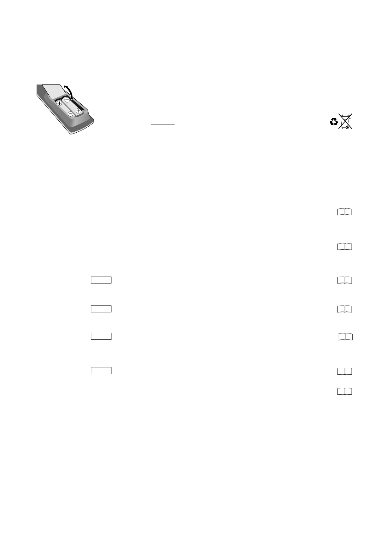
Fit the batteries into
the remote control
Inserting Batteries
The batteries last for about a year, depending on how often you use the remote control unit.
!
Do not mix old with new batteries, or batteries of different types.
!
Only use batteries without any harmful substances (lead, cadmium, mercury).
!
Do not use rechargeable type batteries.
!
Remove the batteries if the remote control unit will remain unused for longer periods of time.
!
Do not heat or short-circuit the batteries.
Immediately remove used-up batteries and replace with batteries of type AA, UM3 or R6.
!
Be sure to put in the batteries the right way round + and -.
Dispose of batteries, packaging material and the unit according to statutory
regulations. They must not be thrown into the household refuse.
Product Introduction
This unit is a DVD recorder with an integrated DVB tuner. This means that you can receive
and record both analogue and terrestrial digital channels without having to connect an
additional DVB receiving unit (set-top box). Your unit has many additional useful features
especially for the digital channels.
DVB only
DVB only
DVB only
DVB only
TV Guide
Electronic programme guide with current information on the programme and a
7-day preview. Broadcasts can also be sorted by categories.
Recording is easy by selecting the desired station.
Edit Profiles
Create profiles (station lists) in which your preferred stations can be sorted and
saved.
Find your favourite stations quickly at the accustomed programme locations.
Banner
When switching stations, Banners appear that immediately display the current
and next programme.
Subtitles
Your can show or hide subtitles (if available for the programme).
Subtitles can also be recorded.
Multi Audio
With Multi Audio, you can choose from different audio channels for a programme.
For example, if a movie is broadcast with Multi Audio, you can listen to the movie
either with the original sound or its English translation.
MHEG
The unit can receive MHEG service.
Q Link
With the Q Link feature, the television accepts analogue stations directly.
A station scan does not need to be performed for the analogue stations.
18
42
52
52
52
52
11
5
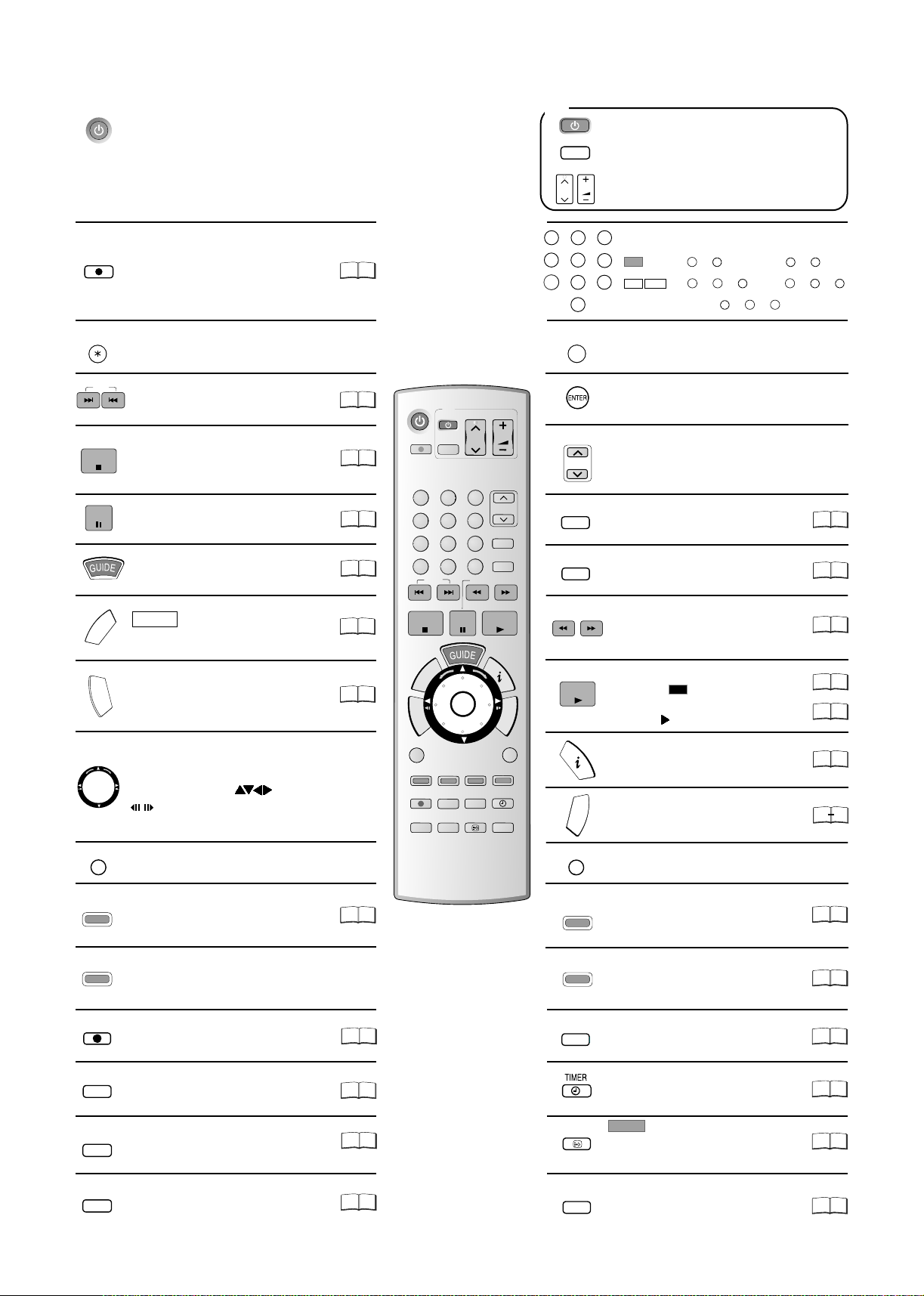
Remote control
Standby/on switch
Press to switch the unit from on to standby mode
or vice versa. In standby mode, the unit is still
consuming a small amount of power.
Switching this unit into standby mode does not
disconnect it from the mains.
TV
Turn the television set on and off.
AV
CH
Select the AV input on the television set.
CH: Select the channel on the television set.
VOLUME
VOLUME: Volume control of the television set.
DIRECT TV REC
Direct TV record to DVD
CANCEL
Cancel button
SKIP
SKIP: Skip chapters, titles or pictures.
Stop recording, replay or forward
STOP
reverse action
PAUSE
Pauses a recording or playback.
Launch the TV Guide.
DVB only
T
X
E
T
R
U
O
T
T
N
DIRECT NAVIGATOR TITLE VIEW
A
C
E
G
E
I
M
R
V
I
A
P
D
N
O
T
TOP MENU: Main menu of DVD-Video.
Direction buttons in the menu navigation.
Selection of groups or titles.
.
/
Launch the MHEG service.
Exit in the MHEG service.
Freeze frame or time loop playback.
1
27
4
7
INPUT SELECT
3
2
5
8
0
Numeric buttons - direct input, example
6
VCD
9
MP3
JPEG
Channel e.g. 800: + +
0
5
5: + 15: +
0 0
5: + + 15: + +
8
Switch button of the AV input between
5
0 0
1
5
0
1
5
AV1, AV2, AV3 (front) and AV4.
23
22
22
18
52
35
DVD
DIRECT TV REC
1
4
7
CANCEL
*
STOP
T
R
O
U
T
T
N
A
C
E
G
I
E
M
V
R
I
A
P
D
N
O
T
SUB MENU
S
MANUAL SKIP
REC
TIME SLIP
SKIP
E
T
X
TV
AV
2
5
8
0
REC MODE
STATUS
INPUT SELECT
PAUSE
ENTER
CREATE
CHAPTER
EXT LINK
VOLUME
CH
PAGE
3
CH
6
VIDEO Plus+
9
DISPLAY
SLOW/SEARCH
PLAY/x1.3
RETURN
ERASE
TIMER
PROG
STTL
CHECK
VIDEO Plus+
SLOW/SEARCH
F
U
N
C
T
I
O
N
S
Select or save a setting
PAGE
PAGE: Page in the electronic TV Guide.
CH
CH: Channel select button.
VIDEO Plus+ menu
DISPLAY
Launch the disc menu.
SLOW/SEARCH: Search or slow
motion playback
Starts playback.
PLAY/x1.3
PLAY/ x1.3
RAM
You can increase the playback speed.
Hold PLAY during playback.
Display the Banner.
F
U
N
C
T
I
O
FUNCTIONS selection menu.
N
S
31
53
23
22
23
52
50
33
SUB MENU
MANUAL SKIP
REC
REC MODE
TIME SLIP
STATUS
6
Launch sub menus.
S
Manual Skip: Jump forwards 30 seconds.
Red Button: Functions in MHEG Service,
Manual Tuning, TV Guide.
Green Button: Functions in MHEG Service,
Edit Profile, TV Guide.
Record
Record mode button (XP, SP, LP, EP)
TIME SLIP: Select the timeframe to
be skipped.
Detail information appears on the screen.
Panasonic
DVD/TV
EUR7729KK0
24
RETURN
Exit a menu.
Create Chapter: Split the recording into
CREATE
CHAPTER
chapters. Yellow Button: Functions in
24
MHEG Service, Edit Profile, TV Guide.
Erase: Erase a title during playback.
ERASE
Blue Button: Functions in MHEG
35
Service, Edit Profile, TV Guide, Banner.
27
28
24
EXT LINK
Record with external recording control.
Switch timer on and off.
STTL
DVB only
Displays or hides subtitles.
Audio L/R function: Press and hold
32
29
52
STTL for more than 5 seconds.
51
PROG
CHECK
TIMER RECORDING menu
29
Remote control
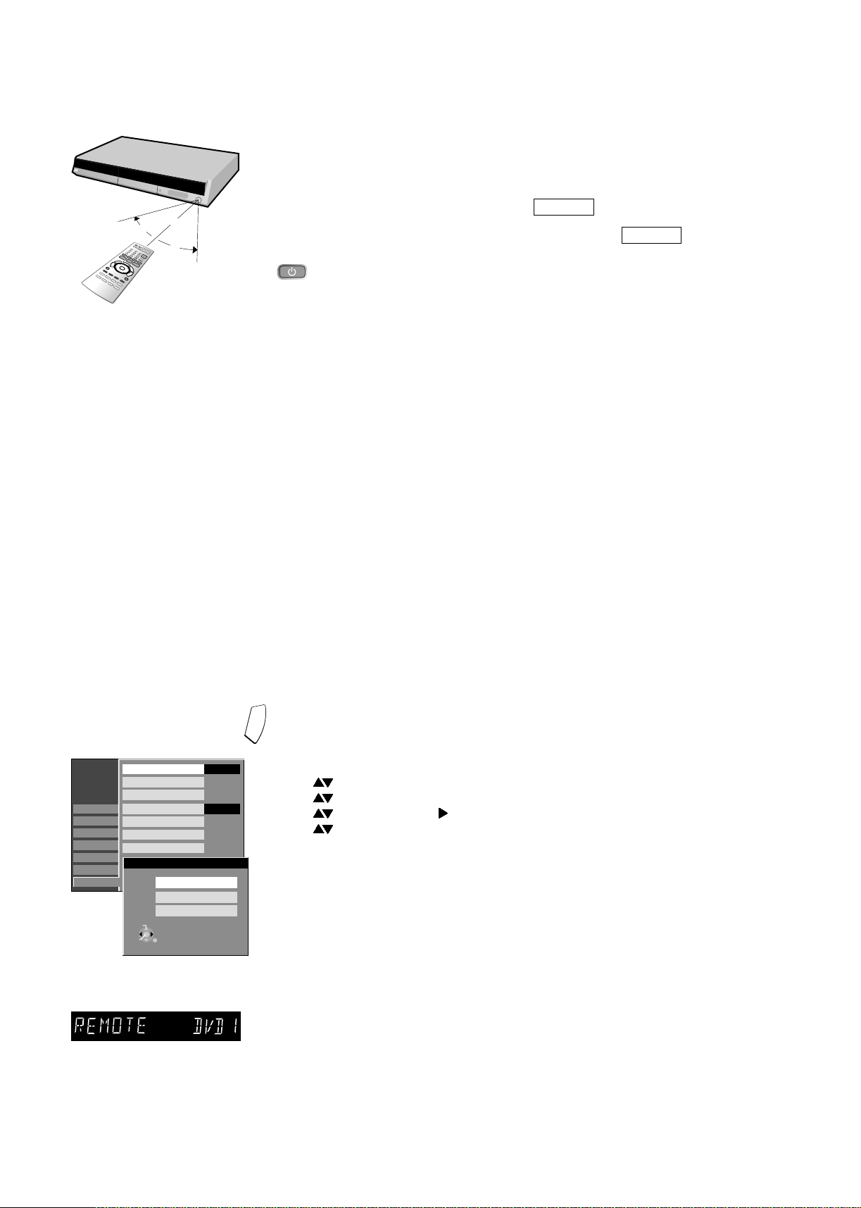
7m
30°
30°
Point the remote control at the unit’s sensor. Avoid obstacles in the path of the
transmission. The maximum range of the remote control is 7 m directly in front of the unit.
Keep the transmission window and the unit sensor clean. The procedure can be impaired
by direct sunlight or doors of glass cabinets.
Child lock
You can lock the buttons of the unit and the remote control.
!
Press and hold RETURN and ENTER until appears in the display.
The unit is now locked.
!
In order to unlock the child lock, repeat the procedure until disappears.
X HOLD
X HOLD
Remote control
signal sensor
Operating a television set
Change the remote control code to operate your television set.
!
Press and hold the TV on and off switch button.
!
Enter the two-digit code for your television set.
The input must be repeated after batteries are changed.
Trademark Code Trademark Code Trademark Code Trademark Code
Panasonic 01-04,45 GOLDSTAR/LG 31 MIVAR 24 SALORA 26
AIWA 35 GOODMANS 05,06,31 NEC 36 SAMSUNG 31,32,43
AKAI 27,30 GRUNDIG 09 NOKIA 25-27 SANSUI 05,31,33
BLAUPUNKT 09 HITACHI 22,23,31,40-42 NORDMENDE 10 SANYO 21
BRANDT 10,15 INNO HIT 34 ORION 37
BUSH 05,06 IRRADIO 30 PHILIPS 05,06
CURTIS 31 ITT 25 PHONOLA 31,33
DESMET 05,31,33 JVC 17,39 PIONEER 38
DUAL 05,06 LOEWE 07 PYE 05,06
ELEMIS 31 METZ 28,31 RADIOLA 05,06
FERGUSON 10 MITSUBISHI 06,19,20 SABA 10
SBR 06
SCHNEIDER 05,06,29-31
SELECO 06,25
SHARP 18
SIEMENS 09
SINUDYNE 05,06,33
SONY 08
TELEFUNKEN 10-14
THOMSON 10,15,44
Some television models of the brands listed above, (e.g. older Panasonic units), cannot
be operated using the remote control.
Switching to AV input on your Panasonic television set
!
Press AV. Each press of the button switches between TV reception and AV input.
If you use another Panasonic device at the same location, change the mode of the
remote control so that you can operate the units independently of each other.
SETUP
Tuning
Disc
Picture
Sound
Display
Connection
Others
Remote Control
Clock
Owner ID
Quick Start
System Update
Shipping Condition
Default Settings
Remote Control
SELECT
TAB
DVD 1
RETURN
SELECT
TAB
DVD 2
Deutsch
RETURN
DVD 3
SELECT
RETURN
ENTER
RETURN
Automatisch
Aus
DVD 1
On
F
U
N
C
T
I
O
Setting the remote control
N
S
Setting the remote control mode for unit.
!
Press FUNCTIONS in stop mode.
!
Use to select [To Others] and confirm with ENTER.
!
Use to select SETUP and confirm with ENTER.
!
Use to select [Others], to select [Remote Control] and confirm with ENTER.
!
Use to select the desired mode [DVD 1, 2 or 3] and confirm with ENTER.
Accept the desired mode on the remote control.
!
Press and hold the
ENTER button for approx. 2 seconds and, at the same time,
enter the number that corresponds to the selected mode (1, 2 or 3).
!
Press RETURN to exit the menu.
If the mode of the remote control does not correspond with that of the unit,
[REMOTE DVD 1 / 2 / 3] will appear on the unit display.
!
Press and hold the ENTER button for approx. 2 seconds and, at the same time,
enter the number that corresponds to the selected mode (1, 2 or 3).
If you want to operate two units independently of each other with the same remote
control, then change the mode of the remote control.
The input must be repeated after batteries are changed.
7
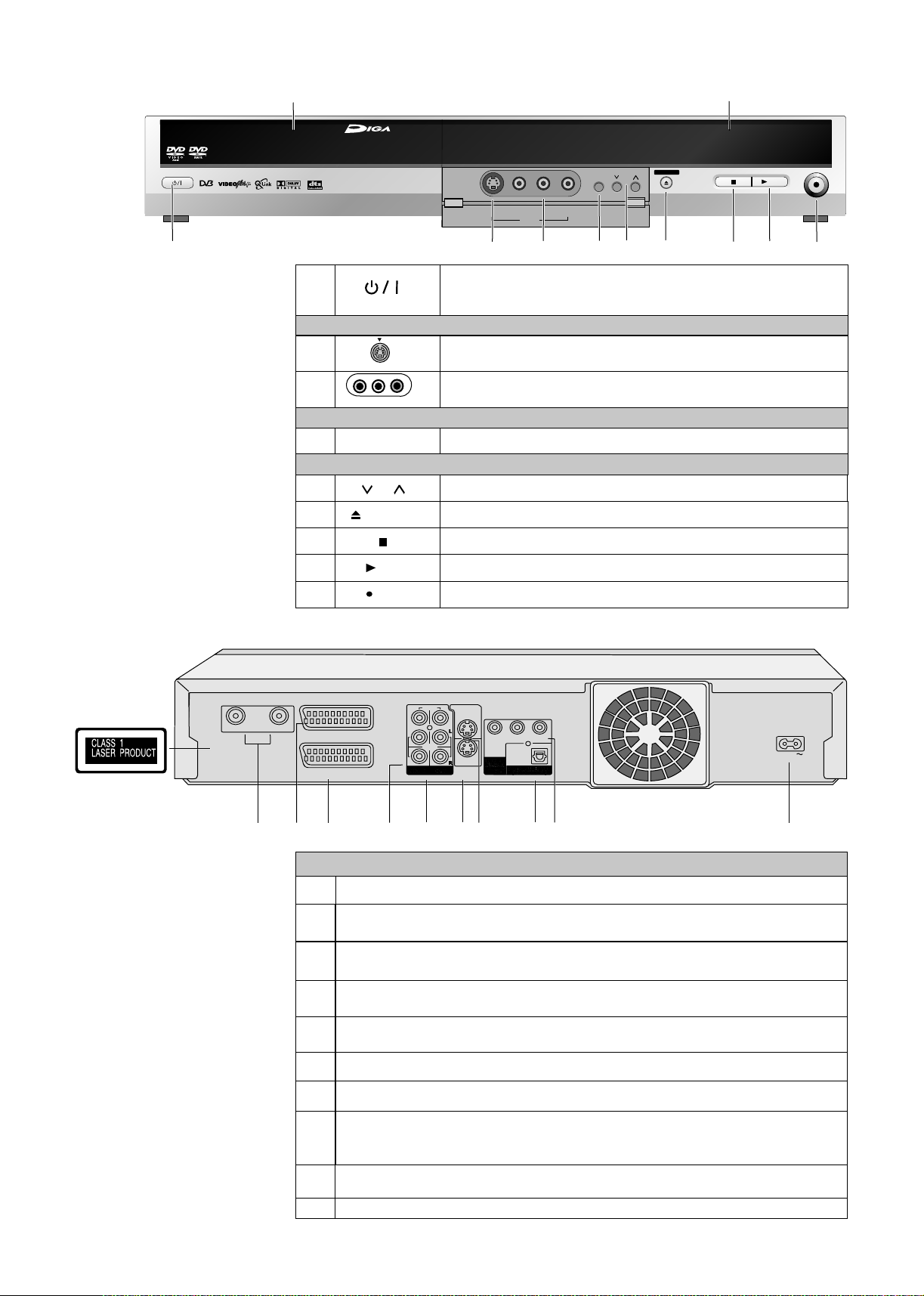
Front Panel
Disc Tray
Display
Panasonic
1
DVD RECORDER DMR-ES20D
1
2
3
4
5
6
7
8
9
S VIDEO IN
L/MONO-AUDIO IN-R
VIDEO IN
EXT LINK
CH
OPEN/CLOSE
/ x1.3
REC
DVD RECORDING
DVD-RAM / DVD-R / DVD-RW / +R
OPEN/CLOSE
CH
6
5
7
S VIDEO IN
2
VIDEO IN
L/MONO - AUDIO IN - R
AV3
3
EXT LINK
4
Standby/on switch
Press to switch the unit from on to standby mode or vice versa. In
standby mode, the unit is still consuming a small amount of power.
Front Connections
S VIDEO Input (AV3)
AV3
AV3 Input Terminal
Front Access
Recording with external recording control
DVD
Channel selector button
Open and close the disc tray
Stop
Playback / x1.3
Record
REC
/x1.3
8
9
Rear Panel
RF OUT
DVD Recorder
S VIDEO OUT
VIDEO
RF IN
AV1 (TV)
AV2 (EXT)
1
2
3
L
AUDIO
R
5
4
S VIDEO
AV4 IN
6
Y
PR
PB
OPTICAL
8
7
9
AC IN
10
Connections
RF OUT = Aerial output
1
AV1 (TV)
2
21-pin Scart socket = TV connection
AV2 (EXT)
3
21-pin Scart socket = connection to an external unit
AV4 IN = Audio input right/left channel
4
OUT = Audio output right/left channel
5
S VIDEO AV4 IN = S VIDEO input socket
6
Video input
Video output
RF IN = Aerial input
7
S VIDEO OUT = S VIDEO output socket
COMPONENT VIDEO OUT (PROGRESSIVE/INTERLACE)
Y
8
9
10
= Luminance signal (luminance)
P
= Chrominance signal (colour difference)
B
OPTICAL DIGITAL AUDIO OUT (PCM BITSTREAM)
= Digital audio output
AC IN~ = Power supply
P
= Chrominance signal (colour difference)
R
8
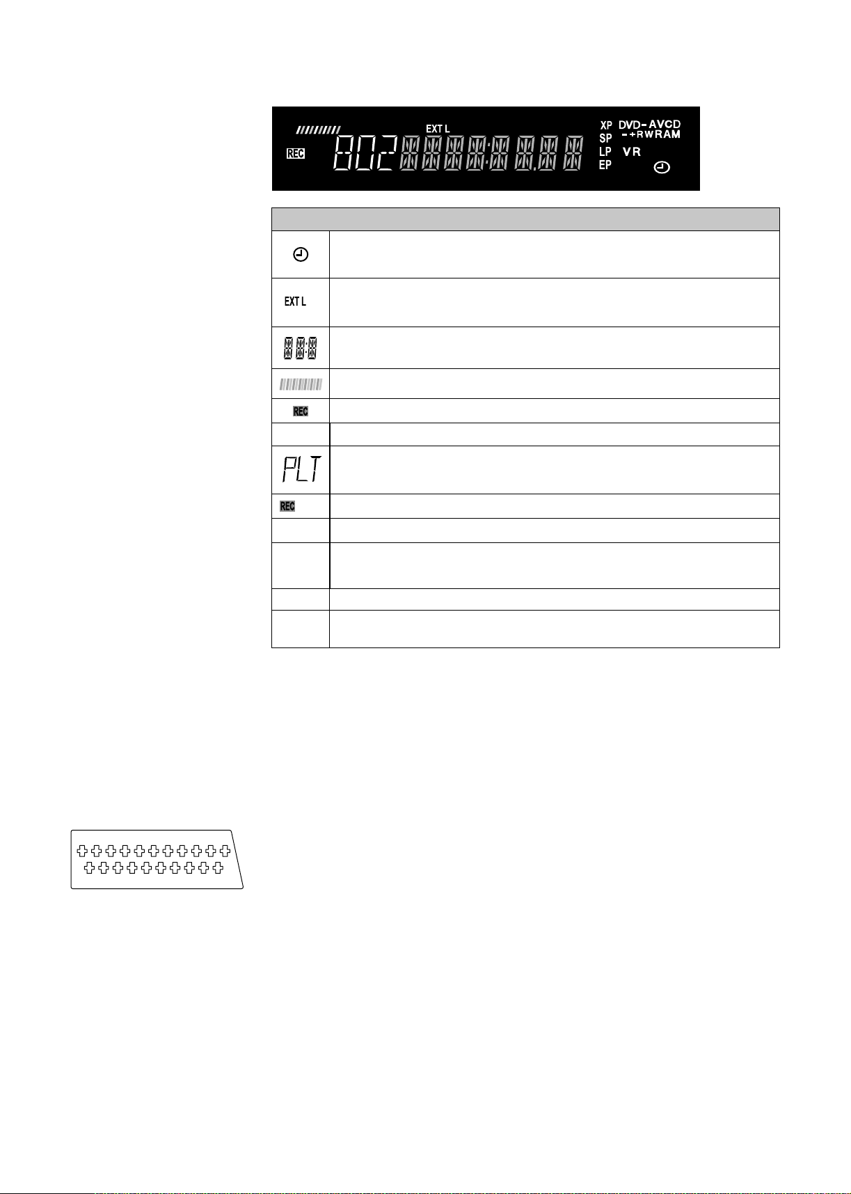
Display
PLAY
PLAY
D
PLAY
ink
D.MIX
Information on the display
TIMER-controlled recording.
Blinking: There are less than 10 minutes until the start of a programmed
TIMER recording. The device is not set to TIMER standby mode.
External-Link display
ink
On: A TIMER-controlled recording is being performed by an external device.
Current time, Disc recording and playback counter,
various messages.
Reading Disc.
Recording
Playback
PL Number of Playlist
T Track number
G Group number
Simultaneous Recording/Playback
T Title number
C Chapter number
100 Channel number
21-pin Scart Socket
21-pin Scart Socket
1 3 5 7 9 11 13 15 17 19
2 4 6 8 10 12 14 16 18 20
D.MIX
XP, SP
LP, EP
D
DVD-RAM
VCD +RW
VR
Down-Mix
Record mode
All on: FR mode (for flexible recordings or TIMER-controlled recordings).
Digital channel
Disc type e.g.: DVD-RAM, DVD-R, ,DVD-RW(VR), DVD-Video, Video-CD.
The 21-pin Scart socket transmits both input and output signals for picture and sound.
TVs equipped with the same type of socket can be connected here.
This type of socket is also called Peritel, Euro Connector and Euro AV.
AV1 Scart Socket (NORMAL)
1 Audio output CH2 (R)
2 Audio input CH2 (R)
21
3 Audio output CH1 (L)
4 Audio ground
5 Blue ground
6 Audio input CH1 (L)
7 Blue
8 Switching voltage
9 Green ground
10 Reserved
11 Green
12 No connection
13 Red ground
14 Blanking ground
15 Red
16 Blanking
17 Video output ground
18 Video input ground
19 Video output
20 Video input
21 Ground
AV2 Scart Socket
1 Audio output CH2 (R)
2 Audio input CH2 (R)
3 Audio output CH1 (L)
4 Audio ground
5 Blue ground
6 Audio input CH1 (L)
7 Blue
8 Switching voltage
9 Green ground
10 Control signal
11 Green
12 Reserved
13 Red ground
14 Blanking ground
15 Red
16 Blanking
17 Video output ground
18 Video input ground
19 Video output
20 Video input
21 Ground
9
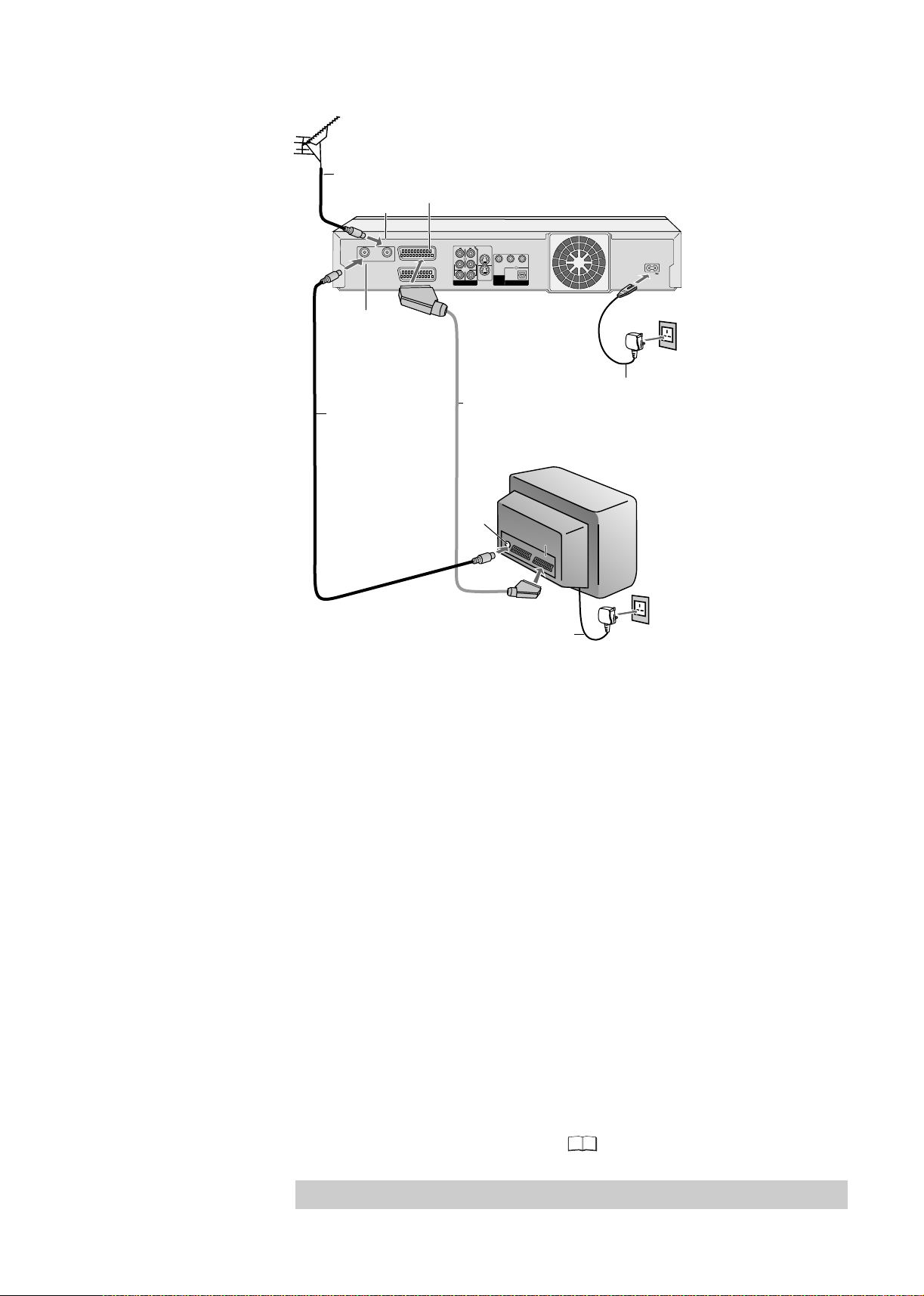
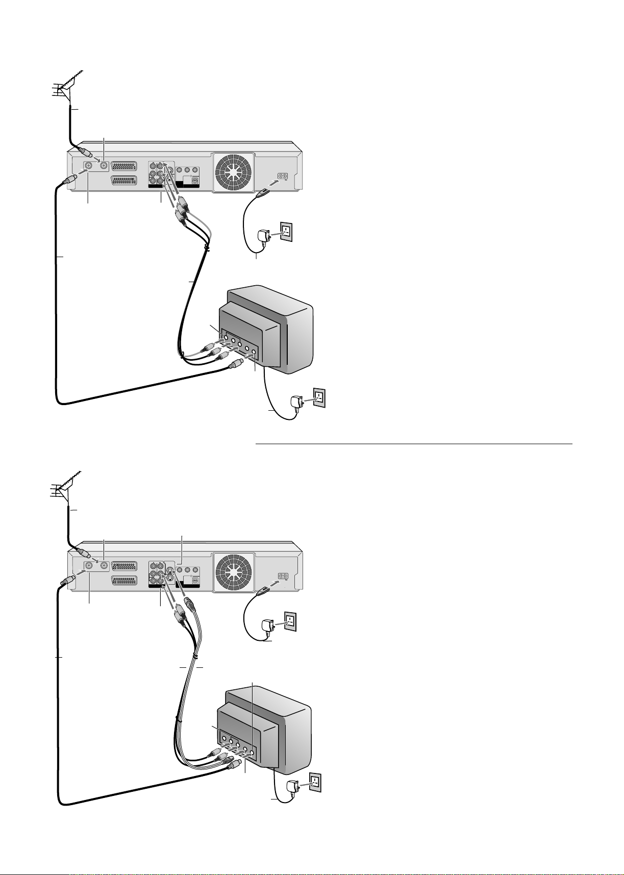
Connecting with a 21-pin Scart cable
1
Aerial
RF cable /
Aerial cable
RF IN
Aerial input
RF IN
RF OUT
Aerial output
RF cable /
2
Aerial cable
RF OUT
AV1 (TV)
AV2 (EXT)
AV1 21-pin Scart socket
DVD Recorder
S VIDEO OUT
VIDEO
L L
Y
AUDIO
COMPONENT
S VIDEO
R
R
VIDEO OUT
AV4 IN
(PROGRESSIVE/
AV4 IN
OUT
INTERLACE)
21-pin Scart cable
3
Necessary for TV with Q-Link
erialA
input
PB
OPTICAL
DIGITAL AUDIO OUT
(PCM/BITSTREAM)
PR
AC IN
AC IN~
AC mains lead
4
TV
AV
1
AC mains lead
4
Follow the steps below.
Disconnect AC mains from all units.
1 Connect the aerial to the RF IN (Aerial input) of the DVD Recorder.
2 Connect the RF OUT (Aerial output) of the DVD Recorder to the Aerial input
of the television set.
3 Connect the AV1 socket (21-pin Scart socket) of the DVD Recorder to the
Scart input of the television set.
4 Connect the DVD Recorder and the television set to the AC mains socket.
If your television supports Q Link follow the steps for Auto-Setup with Q Link on page 11
If your television doesn't support Q Link follow the steps for Auto-Setup without Q Link
on page 11..
10
If your television supports Q Link or RGB, connect it to the DVD Recorder with a fully
wired 21-pin Scart cable.
SETUP - Connection - [AV1 Output]
46
Note For all connections additional cables and equipment shown are not supplied.:
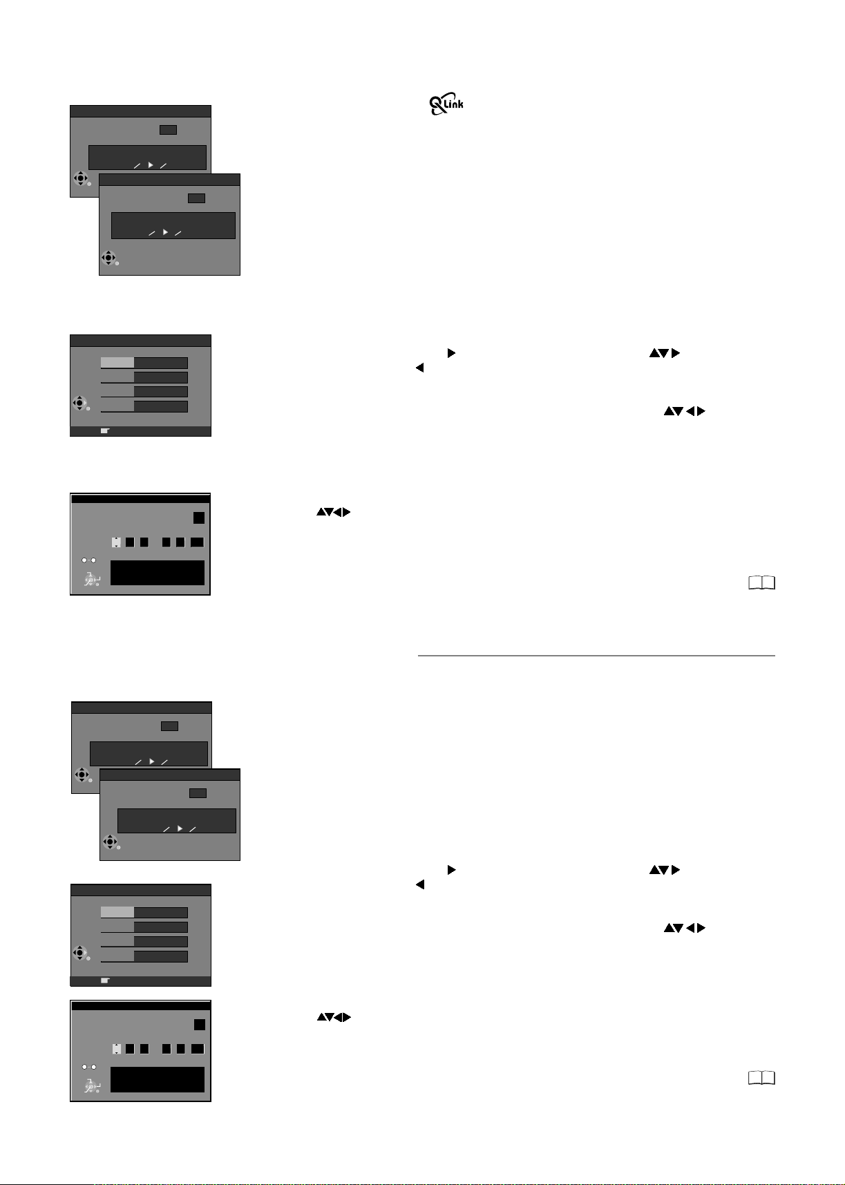
Setup with Q Link
Auto-Setup
4
35
Ch
Suche Sender, bitte warten.
Digital Auto-Setup in progress, please wait.
RETURN: abbrechen
RETURN: to abort
RETURN
RETURN
Download from TV
Pos
Download in progress, please wait.
RETURN: to abort
RETURN
Owner ID
PIN number
* * * *
Name
House No.
Postcode
RETURN : leave
4
Download from TV using
(Registered trademark of Panasonic)
You can download the tuning positions for analogue channels from the TV set.
Time and date will be set automatically by Auto Clock Setting function.
Note that you must first perform a station search if you use the TV for the first time.
If you have a Panasonic television, [Download from TV] will be displayed automatically at
the beginning of the station transfer.
!
Switch your television on and select the AV channel.
!
Switch the device on using the Standby/on switch.
The unit starts the station transfer. A station search for the digital channel starts first.
The number of channels found is displayed on the screen after the station search.
Then the analogue station positions are automatically transferred from the television.
The station transfer is complete when the Owner ID screen appears.
Owner ID
You can complete the Owner ID now or skip this step and do it later. To do it later, press the
RETURN button. Your DVD Recorder is now ready to use.
!
To set the Owner ID now, use and press the Numeric buttons or to enter a fourdigit PIN number. Press , to correct the digit.
!
Make sure that you will remember the PIN number (make a note of it).
!
Press the ENTER button twice to confirm.
!
Enter the [Name], [House No] and [Postcode] in the same way, using .
!
Press the ENTER button to confirm each entry.
!
Press the RETURN button to leave the Owner ID screen.
!
You will now see the TV picture. Your DVD Recorder is now ready to use.
If the clock setting menu appears
CHANGE
ENTER
No
0
9
SELECT
RETURN
Clock
Time Date
: : . .
0
00 00
1 1
Clock cannot be set automatically.
Please set the clock manually.
ENTER: store RETURN: leave
OffAutomatic
2005
(Auto clock set was not possible due to a weak signal)
!
Press to set the correct time and date and press ENTER to finish this setting.
Note: A wrong date or time will influence the programmed recording of TV programmes
(don't forget to change summer time and winter time).
If Auto-Setup has previously been completed the DVD Recorder will not start
Auto-Setup automatically. In this case you can re-start Auto-Setup again.
If you want to cancel Auto-Setup before it has finished, press the RETURN button.
You can restart Auto-Setup again.
Setup without Q Link (Automatic Tuning)
Auto-Setup
Auto-Setup
Ch
Suche Sender, bitte warten.
Digital Auto-Setup in progress, please wait.
RETURN: abbrechen
RETURN: to abort
RETURN
RETURN
CHANGE
ENTER
0
No
RETURN
RETURN
PIN number
House No.
Postcode
9
SELECT
Name
Time Date
Clock cannot be set automatically.
Please set the clock manually.
ENTER: store RETURN: leave
Auto-Setup
Suche Sender, bitte warten.
Analogue Auto-Setup in progress, please wait.
RETURN: abbrechen
RETURN: to abort
Owner ID
* * * *
RETURN : leave
Clock
: : . .
0
00 00
4
35
Ch
1 1
2005
4
35
OffAutomatic
The automatic setup saves all available TV stations. If the station also broadcasts date and
time, then the clock is also set automatically.
!
Switch on your television and select the AV channel.
!
With the Standby/on switch turn on the DVD Recorder.
Automatic tuning for all available TV stations begins. The search is first performed for the
digital and then the analogue stations. The number of channels found is displayed on the
screen after the station search. Approximate duration is 5 minutes.
After Automatic tuning has finished, the Owner ID screen will appear.
Owner ID
You can complete the Owner ID now or skip this step and do it later. To do it later, press the
RETURN button. Your DVD Recorder is now ready to use.
!
To set the Owner ID now, use and press the Numeric buttons or to enter a fourdigit PIN number. Press , to correct the digit.
!
Make sure that you will remember the PIN number (make a note of it).
!
Press the ENTER button twice to confirm.
!
Enter the [Name], [House No] and [Postcode] in the same way, using .
!
Press the ENTER button to confirm each entry.
!
Press the RETURN button to leave the Owner ID screen.
!
You will now see the TV picture. Your DVD Recorder is now ready to use.
If the clock setting menu appears
(Auto clock set was not possible due to a weak signal)
!
Press to set the correct time and date and press ENTER to finish this setting.
Note: A wrong date or time will influence the programmed recording of TV programmes
(don't forget to change summer time and winter time).
If Auto-Setup has previously been completed the DVD Recorder will not start AutoSetup automatically. In this case you can re-start Auto-Setup again. If you want to
cancel Auto-Setup before it has finished, press the RETURN button.
You can restart Auto-Setup again.
43
43
11
Connecting with Audio/Video cable
Aerial
1
RF cable /
Aerial cable
RF IN
Aerial input
DVD Recorder
S VIDEO OUT
VIDEO
L L
AUDIO
S VIDEO
R
R
AV4 IN
AV4 IN
OUT
Audio/Video
output
Audio/Video cable
Y
PR
PB
OPTICAL
COMPONENT
VIDEO OUT
(PROGRESSIVE/
DIGITAL AUDIO OUT
INTERLACE)
(PCM/BITSTREAM)
AC mains lead
4
3
TV
Audio/
Video
input
Aerial output
RF cable /
2
Aerial cable
RF OUT
RF OUT
RF IN
AV1 (TV)
AV2 (EXT)
AC IN
AC IN~
Follow the steps below.
Disconnect the AC mains from all units.
1 Connect the aerial to the RF IN (Aerial input) of
the DVD Recorder.
2 Connect the RF OUT (Aerial output) of the DVD
Recorder to the Aerial input of the television set.
3 Connect the AV4 OUT (AUDIO L/R, VIDEO) of
the DVD Recorder to the input of the television
set.
4 Connect the DVD Recorder and the television set
to the AC mains socket.
Follow the steps for Auto-Setup without Q Link on
page 11.
Aerial input
AC mains lead
Connecting with S VIDEO cable
Aerial
1
RF cable /
Aerial output
RF cable /
2
Aerial cable
Aerial cable
RF IN
Aerial input
RF IN
RF OUT
RF OUT
AV1 (TV)
AV2 (EXT)
Audio output
Audio/Video cable
VIDEO
L L
AUDIO
R
AV4 IN
S VIDEO OUT
S VIDEO
R
AV4 IN
OUT
3
S VIDEO
output
DVD-Recorder
Y
PR
PB
OPTICAL
COMPONENT
VIDEO OUT
(PROGRESSIVE/
DIGITAL AUDIO OUT
INTERLACE)
(PCM/BITSTREAM)
Audio
input
S VIDEO cable
3
Aerial input
4
TV
AC IN
AC IN~
AC mains lead
4
Follow the steps below.
Disconnect the AC mains from all units.
1 Connect the aerial to the RF IN (Aerial input)
of the DVD Recorder.
2 Connect the RF OUT (Aerial output) of the DVD
Recorder to the Aerial input of the television set.
3 Connect the AV4 OUT (AUDIO L/R) of the
DVD Recorder to the input of the television set.
Connect the S VIDEO OUT of the DVD Recorder
to the input of the television set.
4 Connect the DVD Recorder and the television
set to the AC mains socket.
Follow the steps for Auto-Setup without Q Link
on page 11.
12
S VIDEO
input
AC mains lead
4
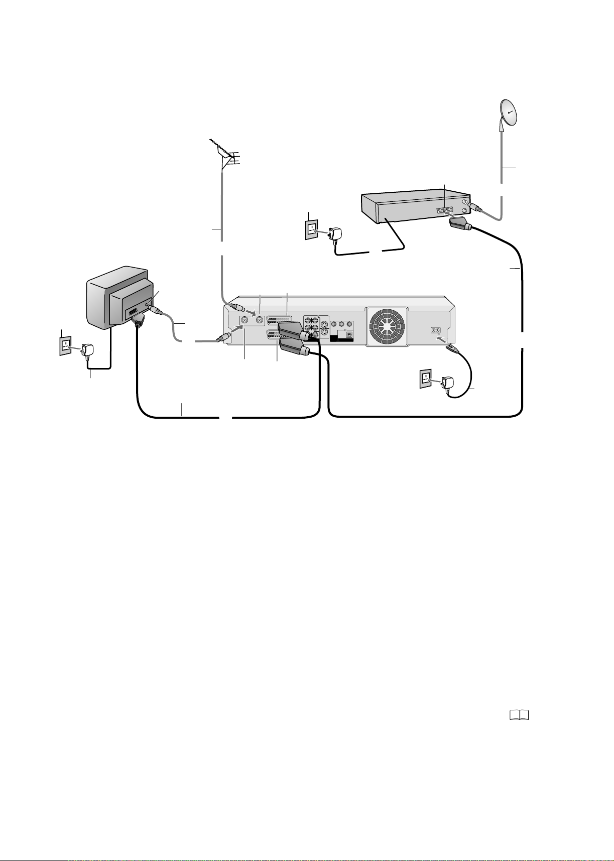
Connecting to a Satellite Receiver
Aerial
RF cable /
Aerial cable
2
AC mains
socket
AC mains lead
3
TV
Aerial input
RF cable /
Aerial cable
2
21-pin Scart cable
RF IN
Aerial input
RF OUT
RF OUT
Aerial output
1
RF IN
AV1 (TV)
AV2 (DECODER/EXT)
(AV2)
AC mains socket
(AV1)
DVD Recorder
VIDEO
L L
AUDIO
R
AV4 IN
To AC mains socket
S VIDEO OUT
Y
PB
OPTICAL
COMPONENT
S VIDEO
R
VIDEO OUT
AV4 IN
(PROGRESSIVE/
DIGITAL AUDIO OUT
OUT
INTERLACE)
(PCM/BITSTREAM)
Parabolic
antenna
Sat cable
21-pin Scart socket
t
li
l
e
t e r e v
a
S
er
i
ec
2
3
PR
21-pin Scart cable
AC IN
1
AC IN~
AC mains
3
lead
Follow the steps below.
Disconnect the all units.AC mains from
1
Connect a 21-pin Scart cable (fully wired) to the AV2 21-pin Scart socket of the DVD
Recorder and to the 21-pin Scart socket of the .
Connect a 21-pin Scart cable (fully wired) to the AV1 21-pin Scart socket of the DVD
Recorder and to the 21-pin Scart socket of the TV set.
Connect aerial to the RF IN (Aerial input) of the DVD Recorder.
2
Connect the parabolic antenna to the Aerial in connector of the satellite receiver.
Connect the DVD Recorder´s RF OUT (Aerial output) to the TV set’s Aerial in
connector.
3
Connect the s , DVD Recorder and TV set to the AC mains supply.atellite receiver
Switch on the TV set and DVD Recorder.
Set the settings for AV2 according to the connected .satellite receiver
Switch on the . Then follow page 11 for Auto-Setup with 21-pin Scart
satellite receiver
cable.
satellite receiver
46
13
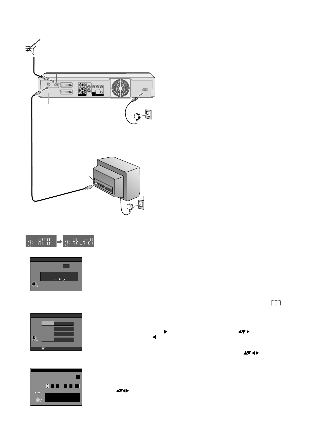
Connecting with RF cable (Aerial cable)
Aerial
1
RF cable /
Aerial cable
RF OUT
RF OUT
Aerial output
RF cable /
2
Aerial cable
RF IN
Aerial input
RF IN
AV1 (TV)
AV2 (EXT)
AC IN
DVD Recorder
S VIDEO OUT
VIDEO
L L
Y
AUDIO
OPTICAL
COMPONENT
S VIDEO
R
R
VIDEO OUT
AV4 IN
(PROGRESSIVE/
OUT
erialA
input
DIGITAL AUDIO OUT
INTERLACE)
AV4 IN
PB
(PCM/BITSTREAM)
PR
AC IN
AC IN~
AC mains lead
3
TV
Follow the steps below.
Disconnect the power of all units.
Connect aerial to the RF IN (Aerial input)
1
connector of the DVD Recorder.
2
Connect the DVD Recorder´s RF OUT (Aerial
output) to the TV set’s Aerial in connector.
Connect DVD Recorder and TV set to the AC
3
mains socket.
Follow the steps for Auto-Setup on page 14.
DVD Display
Suche Sender, bitte warten.
Auto-Setup in progress, please wait.
RETURN: abbrechen
RETURN: to abort
RETURN
PIN number
House No.
Postcode
RETURN
No
0
9
CHANGE
SELECT
ENTER
RETURN
Auto-Setup
4
35
Ch
Owner ID
* * * *
Name
RETURN : leave
Clock
Time Date
: : . .
0
00 00
1 1
Clock cannot be set automatically.
Please set the clock manually.
ENTER: store RETURN: leave
2005
AC mains socket
AC mains lead
3
Auto-Setup with RF cable (Aerial cable) (Automatic tuning)
!
Turn on your television set.
!
With the Standby/on switch turn on the DVD Recorder. Automatic tuning for all available
TV stations begins. Approximate duration is 5 minutes.
- While Auto-Setup is running the first digit of the DVD Recorder display will flash.
After a while it will stop flashing and the RF output channel number will be displayed.
- Select an unused channel pre-set on your TV and tune it to the RF output channel
number shown on the DVD Recorder display (or until you can clearly see the Auto-Setup
screen). Store the new RF output channel (refer to the instructions for your TV).
!
After Automatic tuning has finished, the Owner ID screen will appear.
In some cases, the RF output channel may interfere with the TV stations transmitted in
your area. This may prevent you from seeing the On-Screen Display clearly.
Please see page 15 for removing the interference before restarting Auto-Setup.
Owner ID
You can complete the Owner ID now or skip this step and do it later. To do it later, press the
RETURN button. Your DVD Recorder is now ready to use.
!
To set the Owner ID now, use and press the Numeric buttons or to enter a fourdigit PIN number. Press , to correct the digit.
!
Make sure that you will remember the PIN number (make a note of it).
!
Press the ENTER button twice to confirm.
!
Enter the [Name], [House No] and [Postcode] in the same way, using .
!
Press the ENTER button to confirm each entry.
!
Press the RETURN button to leave the Owner ID screen.
!
You will now see the TV picture. Your DVD Recorder is now ready to use.
OffAutomatic
If the clock setting menu appears
(Auto clock set was not possible due to a weak signal)
!
Press to set the correct time and date and press ENTER to finish this setting.
Note: A wrong date or time will influence the programmed recording of TV programmes
(don't forget to change summer time and winter time).
43
14

Removing Interference /
Changing RF output channel
In some cases, interference (lines or patterning) or a very poor picture may appear
on the TV when the DVD Recorder is connected. If this happens, follow the steps
below to change the RF output channel to remove the interference.
The picture with interference
TV screen
RF OUTPUT CHANNEL
ENTER
SELECT
DVD
CH:
RETURN
21
On-Screen Display
Test pattern indication
DVD display
Indication when the RF output
channel is 21 (example)
Indication after changing the RF
output channel to 31 (example)
RF OUTPUT CHANNEL
ENTER
SELECT
DVD
31
CH:
RETURN
Test pattern indication
The clear picture
F
U
N
C
!
Press the FUNCTIONS button for more than 5 seconds. The RF output channel
T
I
O
N
S
number is displayed on the DVD display.
PAGE
!
Press the Numeric buttons or use the Channel (CH) button to select
CH
a channel number, which differs at least by 2 or 3 from the present
channel number. (For example, if the original channel number was
28, enter 31.)
!
Retune your TV until you receive the Test pattern. It may be necessary to
repeat steps above until you can see the Test pattern clearly.
If using a Scart cable please see the note below.
!
Press ENTER to finish this setting.
Set the RF output channel of the DVD Recorder to [- -] (RF OFF) if the DVD
Recorder is connected to the TV via the 21-pin Scart cable.
!
FUNCTIONS
Press for about 5 seconds. The preset channel will be displayed on
the DVD display.
!
Press channel select buttons CH or 0 to invoke [- -].
!
Confirm with ENTER.
...
21
68
(RF OFF)
1
4
7
3
2
6
5
9
8
0
Checking the Settings after Auto-Setup
F
U
!
N
Press FUNCTIONS to display the FUNCTIONS Menu.
C
T
I
O
!
N
Press to select [To Others] and then press ENTER.
FUNCTIONS
ENTER
RETURN
SETUP
Tuning
Disc
Picture
Sound
Display
Connection
Others
DVD-RAM
DIRECT NAVIGATOR
TV Guide
TIMER RECORDING
VIDEO Plus+
To Others
Edit Profiles
Auto-Setup Restart
Digital
Add New DVB Service
Signal Quality
Analogue
Manual
Download from TV
SELECT
ENTER
RETURN
Delete
Disc Protection Off
PLAYLISTS
FLEXIBLE REC
SETUP
DISC MANAGEMENT
Name
Pos
901
BBC1
BBC2
902
903
ITV 24
CH4 25
904
CH5 26
905
906
* * * *
907
908
909
910
Return
Manual Tuning
Name
Pos
Ch
22
911
912
23
913
914
915
916
30
917
918
919
920
S
!
Press to select and then press ENTER.SETUP
!
Press to select Manual and then press ENTER to display the list of tuned TV
stations and confirm that all available TV stations have been set correctly.
If station name is [ ]:
The asterisks indicate that a station was found during Auto-Setup but has not been
named (due to weak signal).
The stations in the list with asterisk will need to be named manually.
If station name is [- - - -]:
The dashes represent unused channel positions.
You can set stations manually if you want to.
RETURN
!
Press RETURN to exit the On Screen Display.
Ch
When the station names have not been set correctly, see page 44 for details.
When no station has been found, confirm all connections of the DVD Recorder
again and restart the Auto-Setup. See page 43 for details.
!
Check and sort your digital channel in the Setup menu under [Edit Profiles].
See page 42 for details.
[]
44
44
TV Reception Channels
15
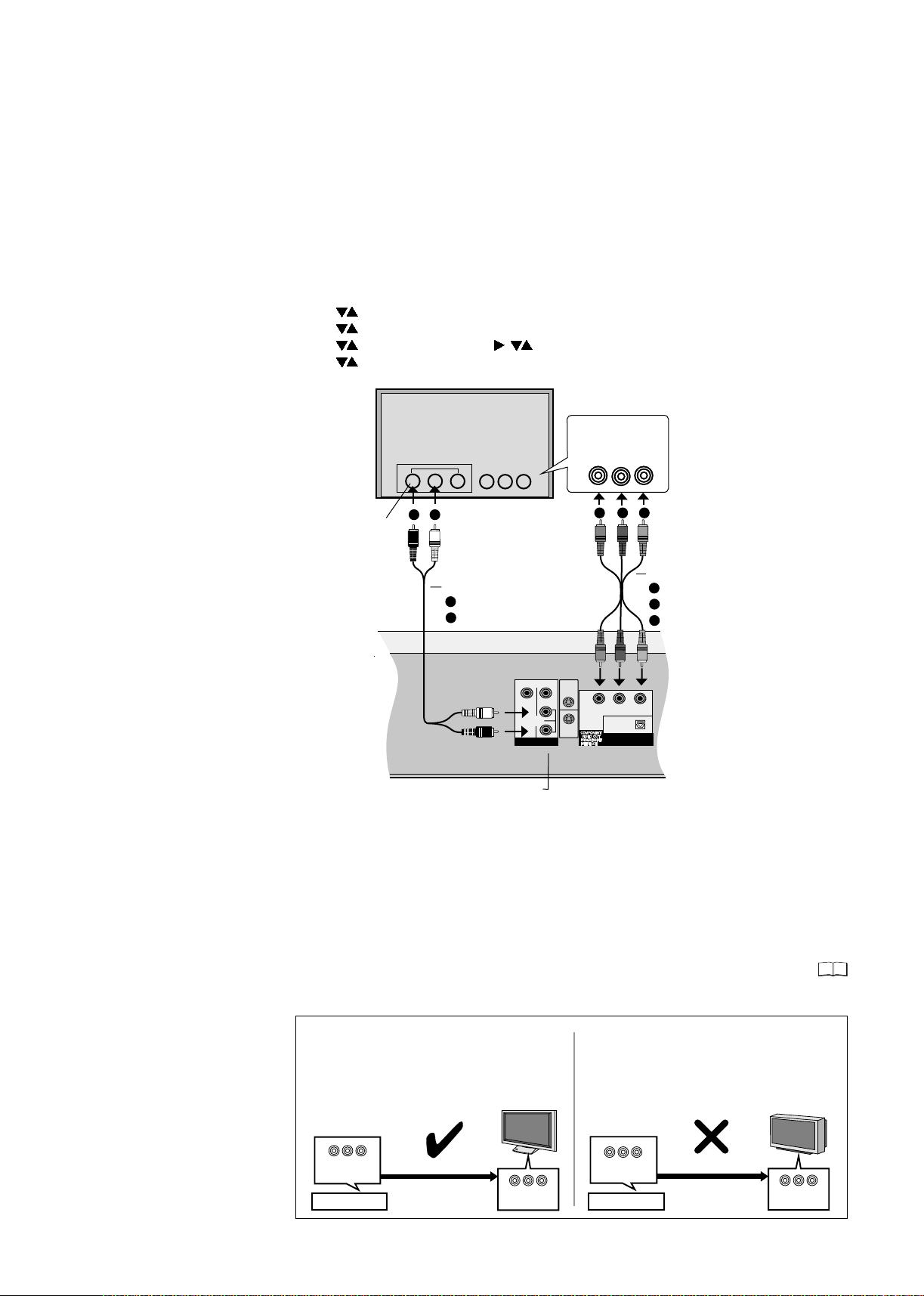
COMPONENT VIDEO OUT
COMPONENT VIDEO OUT socket
These sockets can be used for interlace or progressive output and deliver a clearer picture
than the S VIDEO OUT socket. Connections via these sockets output colour difference
signals (P /P ) and brightness signal (Y) separately. The properties of the COMPONENT
VIDEO input socket are dependent on the television set or screen.
Always connect sockets of the same colour.
Connect the Audio cable to the corresponding audio input sockets of the television.
Connecting a television with COMPONENT VIDEO input sockets
If your television with LCD or plasma screen supports the progressive procedure,
connect it to the COMPONENT VIDEO OUT sockets.
If you want to enjoy progressive-quality video, set Progressive to [On].
!
!
!
!
!
BR
Press FUNCTIONS in stop mode.
Use to select [To Others] and confirm with ENTER.
Use to select SETUP and confirm with ENTER.
Use to select [Connection], , to select [Progressive] and confirm with ENTER.
Use to the select the [On] option and confirm with ENTER.
TV
COMPONENT
VIDEO IN
Y
P
R
P
B
A
Audio
input
L/R
A
B
Audio cable
A
Red/R
B
White/L
B C
Video cable
A
Green/Y
B
Blue/PB
C
Red/PR
S VIDEO OUT
VIDEO
L
AUDIO
S VIDEO
AV4 IN
R
OUT
Y
DIGITAL AUDIO OUT
P
B
OPTICAL
(PCM BITSTREAM)
P
R
AUDIO OUT L/R
If the AV1 Output setting in the SETUP menu is set to [RGB (without component)], no
output will be available from the COMPONENT VIDEO OUT sockets. Set this option to
[Video (with component)].
If the unit is connected to the television via the VIDEO OUT, the S VIDEO OUT or the AV1
socket, output takes place in the interlace format regardless of the settings.
Progressive television picture
The progressive aspect ratio (height to width) is set to 16:9. DVD-Video with an aspect ratio
of 16:9 will be displayed properly. However, video material with an aspect ratio of 4:3 will be
displayed stretched to the right and left. If it is possible to adjust the aspect ratio of
your television for progressive images, set the Progressive setting to [On].
46
Information for Progressive-compatible televisions (PAL)
LCD/plasma TVs or LCD projectors
If Progressive output is used, videos can be viewed
at a high resolution, e.g. from DVD-Video. The
Component Video Output of this unit is connected
with the television set. Set Progressive to [On].
Conventional TVs
In normal televisions, progressive output can lead
to flickering, even if the television is progressivecompatible. Make sure that the Progressive
setting is set to [Off].
16
COMPONENT
VIDEO OUTPUT
DVD-Recorder
Progressive output
COMPONENT
VIDEO IN
COMPONENT
VIDEO OUTPUT
DVD-Recorder
Progressive output
COMPONENT
VIDEO IN
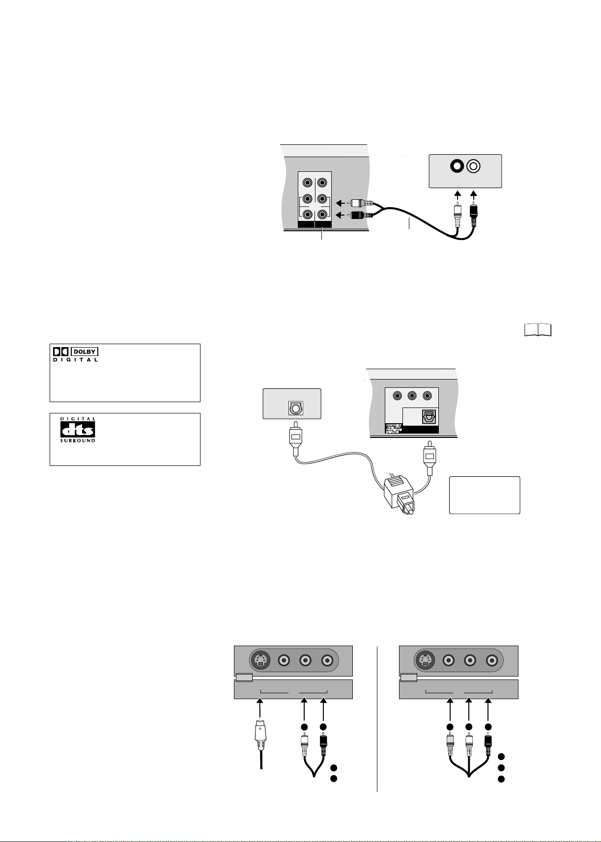
External devices
Connecting an analogue amplifier or an analogue system component
In order to enjoy stereo or Dolby Pro Logic, connect the appropriate amplifier
or an analogue audio component.
!
Connect the analogue output (L/R) e.g. to a Dolby Pro Logic amplifier.
!
As described, connect the Audio cable according to the colours and markings
of the connection sockets (white/L, red/R).
Amplifier (example)
VIDEO
L
R
AUDIO
AV4 IN OUT
L
R
AUDIO OUT (L/R)
White/L
Audio cable
R
AUDIO IN
L
Red/R
Connecting a digital amplifier or a digital system component
!
Connect an amplifier with a Dolby Digital-, DTS- or MPEG decoder.
!
Use an optical digital audio cable.
!
This device can playback
In the Sound SETUP menu, change the [Digital Audio Output] setting
according to your connected digital amplifier.
You cannot use DTS Digital Surround decoders that are not suitable for DVD.
45
stereo sound in Dolby Digital
(2 channels). Connect an
amplifier with built-in Dolby
Digital decoder in order to be
able to enjoy Surround Sound.
Connect this unit to a device
with a DTS decoder in order to
be able to play DVDs with this
symbol.
Amplifier (example)
OPTICAL
Optical digital
audio cable
Y
OPTICAL
DIGITAL AUDIO OUT
P
B
(PCM BITSTREAM)
P
R
Push the jack all the
way into the socket
with this side facing
up.
Connecting to the AV3 input sockets (e.g. Camcorder)
Before you connect the cable, make sure that the power to both devices is
turned off. After you have connected the cables, switch both devices on.
If the audio output of the other device is mono, connect it to the L/MONO socket.
Both the left and the right channels will be recorded if the connection is made via
the L/MONO socket.
Choose one of the two connection possibilities.
Connection with S VIDEO cable and audio cable (L/R) produces the best quality.
S VIDEO IN
VIDEO IN
L/MONO - AUDIO IN - R
AV3
A
B
S VIDEO IN
VIDEO IN
A
L/MONO - AUDIO IN - R
AV3
B
C
Audio/
Video cable
A
Yellow (Video)
B
White (L)
C
Red (R)
S VIDEO cable
Audio/
Video cable
A
White (L)
B
Red (R)
17
 Loading...