

Panasonic DMR-ES16PC /PL Schematic
Vol. 1
Colour
(S).......................Silver Type
ORDER NO.CHM0703009CE
DVD Recorder
© 2007 Matsushita Electric Industrial Co., Ltd. All
rights reserved. Unauthorized copying and
distribution is a violation of law.
DMR-ES16PC / DMR-ES16PL
CONTENTS
Page Page
1 Safety Precaution 4
1.1. General guidelines
1.2. Caution for fuse replacement (ES16PC ONLY)
2 Warning
2.1. Prevention of Electrostatic Discharge (ESD) to
Electrostatic Sensitive (ES) Devices
2.2. Precaution of Laser Diode
2.3. Service caution based on legal restrictions
2.4. How to replace the Lithium Battery (ES16PL ONLY)
3 Service Navigation
3.1. Service Information
4 Specifications
5 Feature
5.1. About DivX
6 Location of Controls and Components
7 Operation Instructions
7.1. Taking out the Disc from DVD-Drive Unit when the Disc
cannot be ejected by OPEN/CLOSE button
8 Service Mode
8.1. Self-Diagnosis and Special Mode Setting
9 Service Fixture & Tools
10 Disassembly and Assembly Instructions
10.1. Disassembly Flow Chart (ES16PC)
10.2. P.C.B. Positions (ES16PC)
10.3. Top Case (ES16PC)
10.4. Front Panel (ES16PC)
10.5. RAM/Digital P.C.B. Module (ES16PC)
10.6. DV Jack P.C.B. (ES16PC)
10.7. Front (L) P.C.B. (ES16PC)
10.8. Rear Panel (ES16PC)
10.9. Main P.C.B. (ES16PC)
10.10. Disas sembly Flow Chart (ES16PL)
10.11. P.C.B . Positions (ES16PL)
10.12. Top Case (ES16PL)
10.13. Front Panel (ES16PL)
10.14. RAM/ Digital P.C.B. Modu le (ES16PL)
10.15. DV Jack P.C.B. (ES16 PL)
10.16. Front (L) P.C.B. (ES16 PL)
10.17. Rear Panel (ES16PL)
10.18. Powe r P.C.B. (ES16 PL ONLY)
10.19. Main P.C.B. (ES16PL)
11 Measurements and Adjustments
11.1. Service Positions (ES16PC)
11.2. Service Positions (ES16PL)
11.3. Notice after replacing RAM/Digital P.C.B. Module
11.4. Caution for Replacing Parts
10
11
11
16
17
17
19
19
27
28
28
28
29
29
29
30
30
31
31
32
32
33
33
33
34
34
35
35
35
36
36
38
41
41
4
4
5
5
6
7
8
9
9
11.5. Standard Inspection Specifications after Making Repairs
(ES16PC)
11.6. Standard Inspection Specifications after Making Repairs
(ES16PL)
12 Block Diagram
12.1. Power Supply Block Diagram (ES16PC)
12.2. Power Supply Block Diagram (ES16PL)
12.3. Analog Video Block Diagram
12.4. Analog Audio Block Diagram
12.5. Analog Timer Block Diagram
13 Schematic Diagram
13.1. Interconnection Schematic Diagram
13.2. Power Supply Section (Main P.C.B. (1/3)) Schematic
Diagram (P) (ES16PC)
13.3. A/V I/O (1/4) Section (Main P.C.B. (2/3)) Schematic
Diagram (A) (ES16PC)
13.4. A/V I/O (2/4) Section (Main P.C.B. (2/3)) Schematic
Diagram (A) (ES16PC)
13.5. A/V I/O (3/4) Section (Main P.C.B. (2/3)) Schematic
Diagram (A) (ES16PC)
13.6. A/V I/O (4/4) Section (Main P.C.B. (2/3)) Schematic
Diagram (A) (ES16PC)
13.7. Timer (1/4) Section (Main P.C.B. (3/3)) Schematic
Diagram (FL) (ES16PC)
13.8. Timer (2/4) Section (Main P.C.B. (3/3)) Schematic
Diagram (FL) (ES16PC)
13.9. Timer (3/4) Section (Main P.C.B. (3/3)) Schematic
Diagram (FL) (ES16PC)
13.10. Timer (4/4) Section (Main P.C.B . (3/3)) Schem atic
Diagram (FL) (ES16PC)
13.11. Sub Power Section (Main P.C.B. (1/31)) Schematic
Diagram (P) (ES16PL)
13.12. A/V I/O (1/4) Sectio n (Main P.C.B . (2/3)) Schem atic
Diagram (A) (ES16PL)
13.13. A/V I/O (2/4) Sectio n (Main P.C.B . (2/3)) Schem atic
Diagram (A) (ES16PL)
13.14. A/V I/O (3/4) Sectio n (Main P.C.B . (2/3)) Schem atic
Diagram (A) (ES16PL)
13.15. A/V I/O (4/4) Sectio n (Main P.C.B . (2/3)) Schem atic
Diagram (A) (ES16PL)
13.16. Timer (1/4) Section (Main P.C.B . (3/3)) Schem atic
Diagram (FL) (ES16PL)
13.17. Timer (2/4) Section (Main P.C.B . (3/3)) Schem atic
Diagram (FL) (ES16PL)
13.18. Timer (3/4) Section (Main P.C.B . (3/3)) Schem atic
Diagram (FL) (ES16PL)
42
43
45
45
47
49
50
51
53
53
54
56
57
58
59
61
62
63
64
66
67
68
69
70
72
73
74
2

13.19. Timer (4/4) Section (Main P.C.B . (3/3)) Schem atic
Diagram (FL) (ES16PL)
13.20. Front (L) Schematic Diagram
13.21. DV Jack Schematic Diagram
14 Printed Circuit Board
14.1. Main P.C.B. (ES16PC)
14.2. Main P.C.B. (ES16PL)
14.3. Front (L) P.C.B.
14.4. DV Jack P.C.B.
15 Appendix for Schematic Diagram
75
77
77
79
79
84
89
15.1. Voltage and Waveform Chart
15.2. Waveform Chart (ES16PC)
15.3. Waveform Chart (ES16PL)
15.4. Abbreviations
16 Parts and Exploded Views
16.1. Exploded Views
16.2. Replacement Parts List
90
DMR-ES16PC / DMR-ES16PL
91
91
96
97
98
100
100
104
3
DMR-ES16PC / DMR-ES16PL
1 Safety Precaution
1.1. General guidelines
1. When servicing, observe the original lead dress. If a short circuit is found, replace all parts which have been overheated or
damaged by the short circuit.
2. After servicing, see to it that all the protective devices such as insulation barriers, insulation papers shields are properly
installed.
3. After servicing, make the following leakage current checks to prevent the customer from being exposed to shock hazards.
1.1.1. Leakage current cold check
1. Unplug the AC cord and connect a jumper between the two
prongs on the plug.
2. Measure the resistance value, with an ohmmeter, between
the jumpered AC plug and each exposed metallic cabinet
part on the equipment such as screwheads, connectors,
control shafts, etc. When the exposed metallic part has a
return path to the chassis, the reading should be between
1MW and 5.2MW.
When the exposed metal does not have a return path to the
chassis, the reading must be
.
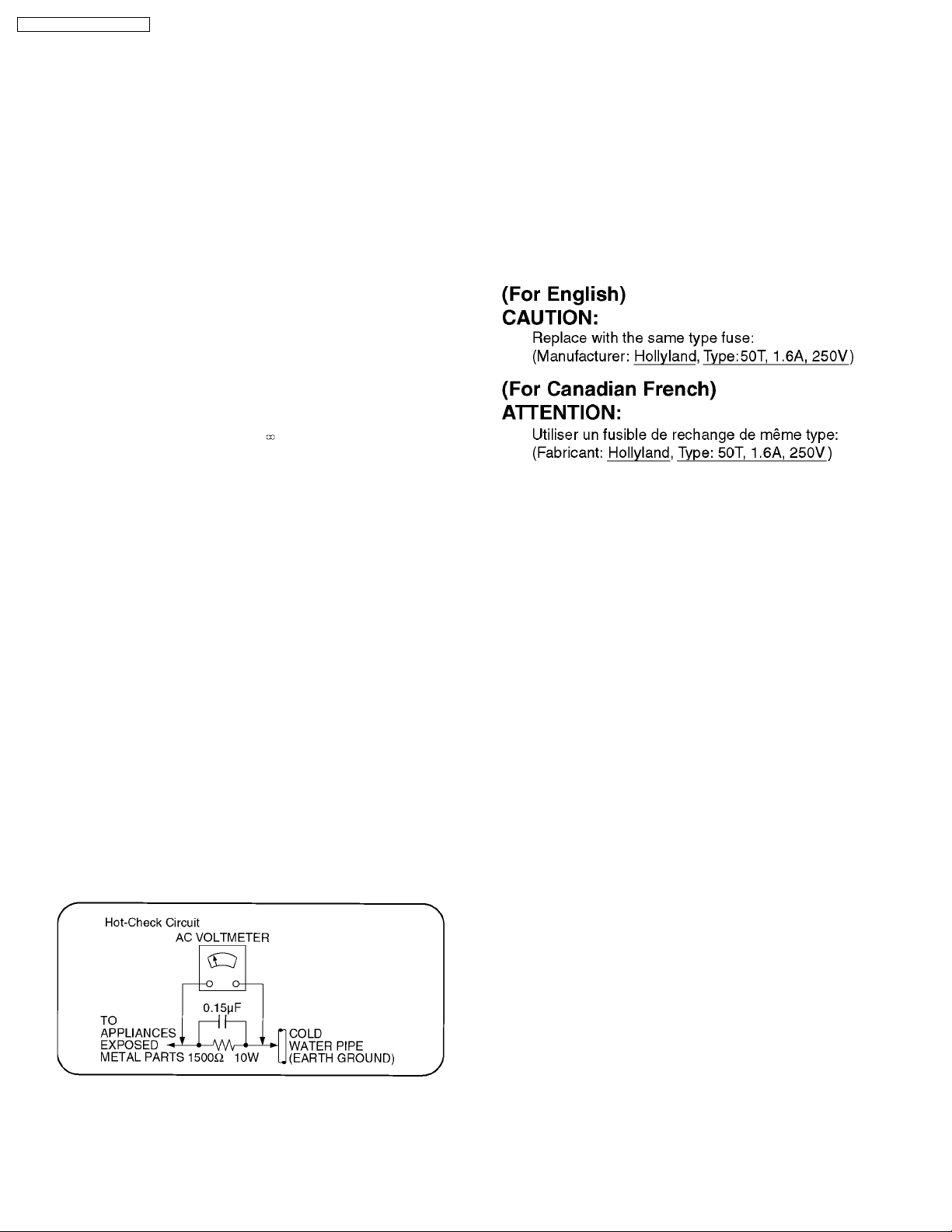
1.1.2. Leakage current hot check
(See Figure 1 .)
1. Plug the AC cord directly into the AC outlet. Do not use an
isolation transformer for this check.
2. Connect a 1.5kW, 10 watts resistor, in parallel with a 0.15µF
capacitors, between each exposed metallic part on the set
and a good earth ground such as a water pipe, as shown in
Figure 1.
3. Use an AC voltmeter, with 1000 ohms/volt or more
sensitivity, to measure the potential across the resistor.
4. Check each exposed metallic part, and measure the
voltage at each point.
5. Reverse the AC plug in the AC outlet and repeat each of the
above measurements.
6. The potential at any point should not exceed 0.75 volts
RMS. A leakage current tester (Simpson Model 229 or
equivalent) may be used to make the hot checks, leakage
current must not exceed 1/2 milliampere. In case a
measurement is outside of the limits specified, there is a
possibility of a shock hazard, and the equipment should be
repaired and rechecked before it is returned to the
customer.
1.2. Caution for fuse replacement
(ES16PC ONLY)
Figure 1
4
DMR-ES16PC / DMR-ES16PL
2 Warning
2.1. Prevention of Electrostatic Discharge (ESD) to Electrostatic Sensitive
(ES) Devices
Some semiconductor (solid state) devices can be damaged easily by static electricity. Such components commonly are called
Electrostatic Sensitive (ES) Devices. Examples of typical ES devices are integrated circuits and some field-effect transistor-sand
semiconductor "chip" components. The following techniques should be used to help reduce the incidence of component damage
caused by electrostatic discharge (ESD).
1. Immediately before handling any semiconductor component or semiconductor-equipped assembly, drain off any ESD on your
body by touching a known earth ground. Alternatively, obtain and wear a commercially available discharging ESD wrist strap,
which should be removed for potential shock reasons prior to applying power to the unit under test.
2. After removing an electrical assembly equipped with ES devices, place the assembly on a conductive surface such as
aluminum foil, to prevent electrostatic charge buildup or exposure of the assembly.
3. Use only a grounded-tip soldering iron to solder or unsolder ES devices.
4. Use only an anti-static solder removal device. Some solder removal devices not classified as "anti-static (ESD protected)" can
generate electrical charge sufficient to damage ES devices.
5. Do not use freon-propelled chemicals. These can generate electrical charges sufficient to damage ES devices.
6. Do not remove a replacement ES device from its protective package until immediately before you are ready to install it. (Most
replacement ES devices are packaged with leads electrically shorted together by conductive foam, aluminum foil or comparable
conductive material).
7. Immediately before removing the protective material from the leads of a replacement ES device, touch the protective material
to the chassis or circuit assembly into which the device will be installed.
Caution
Be sure no power is applied to the chassis or circuit, and observe all other safety precautions.
8. Minimize bodily motions when handling unpackaged replacement ES devices. (Otherwise hamless motion such as the brushing
together of your clothes fabric or the lifting of your foot from a carpeted floor can generate static electricity sufficient to damage
an ES device).
5
DMR-ES16PC / DMR-ES16PL
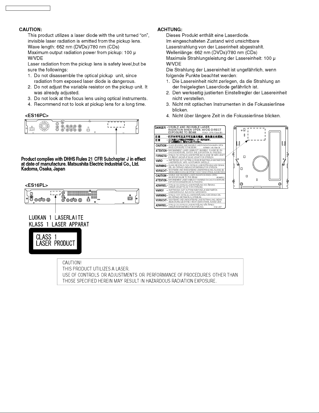
2.2. Precaution of Laser Diode
6
DMR-ES16PC / DMR-ES16PL
2.3. Service caution based on legal restrictions
2.3.1. General description about Lead Free Solder (PbF)
The lead free solder has been used in the mounting process of all electrical components on the printed circuit boards used for this
equipment in considering the globally environmental conservation.
The normal solder is the alloy of tin (Sn) and lead (Pb). On the other hand, the lead free solder is the alloy mainly consists of tin
(Sn), silver (Ag) and Copper (Cu), and the melting point of the lead free solder is higher approx.30 degrees C (86°F) more than that
of the normal solder.
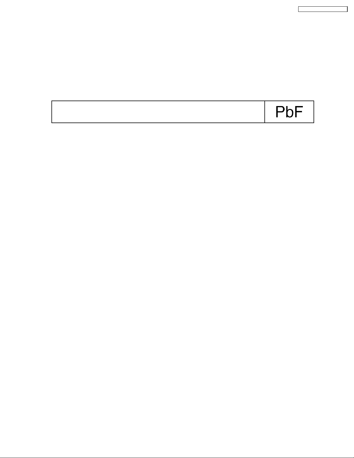
Definition of PCB Lead Free Solder being used
The letter of “PbF” is printed either foil side or components side on the PCB using the lead free solder.
(See right figure)
Service caution for repair work using Lead Free Solder (PbF)
·
· The lead free solder has to be used when repairing the equipment for which the lead free solder is used.
· ·
(Definition: The letter of “PbF” is printed on the PCB using the lead free solder.)
·
· To put lead free solder, it should be well molten and mixed with the original lead free solder.
· ·
·
· Remove the remaining lead free solder on the PCB cleanly for soldering of the new IC.
· ·
·
· Since the melting point of the lead free solder is higher than that of the normal lead solder, it takes the longer time to melt
· ·
the lead free solder.
·
· Use the soldering iron (more than 70W) equipped with the temperature control after setting the temperature at 350±30
· ·
degrees C (662±86°F).
Recommended Lead Free Solder (Service Parts Route.)
·
· The following 3 types of lead free solder are available through the service parts route.
· ·
RFKZ03D01K-----------(0.3mm 100g Reel)
RFKZ06D01K-----------(0.6mm 100g Reel)
RFKZ10D01K-----------(1.0mm 100g Reel)
Note
* Ingredient: tin (Sn), 96.5%, silver (Ag) 3.0%, Copper (Cu) 0.5%, Cobalt (Co) / Germanium (Ge) 0.1 to 0.3%
7
DMR-ES16PC / DMR-ES16PL
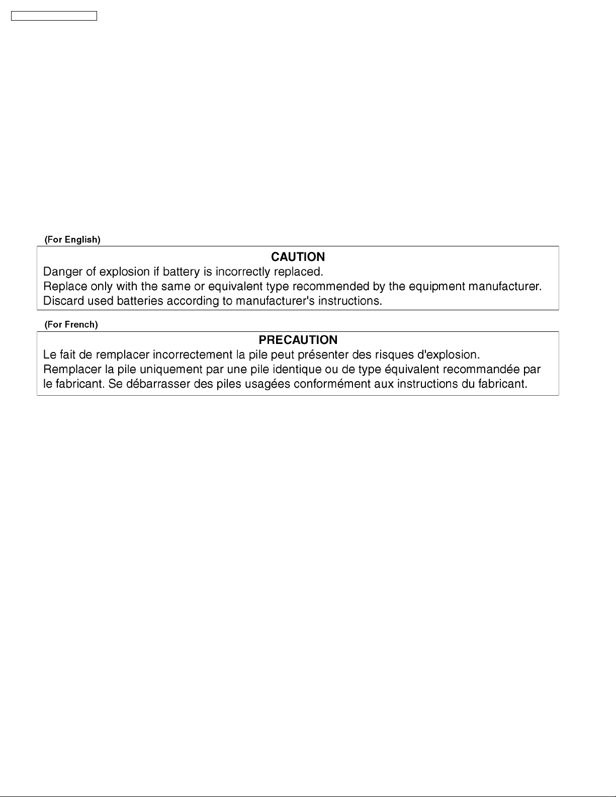
2.4. How to replace the Lithium Battery (ES16PL ONLY)
REPLACEMENT PROCEDURE
1. Remove the Top case, Front Panel, RAM/Digital P.C.B. Module, DV Jack, Rear Panel, Front (L) P.C.B. and Main P.C.B. by
referring the Disassembling Procedure.
2. Unsolder the Lithium Batteries: B7501 and then replace it into new one.
( As shown in 13.3.4. The Main P.C.B. )
NOTE:
The lithium battery is a critical component. ( Type No.: CR2354-1GUFE Manufactured by Panasonic.)
It must never be subjected to excessive heat or discharge.
It must therefore only be fitted in equipment designed specifically for its use.
Replacement batteries must be of the same type and manufacture.
They must be fitted in the same manner and location as the original battery, with the correct polarity contacts observed.
Do not attempt to re-charge the old battery or re-use it for any other purpose.
It should be disposed of in waste products destined for burial rather than incineration.
8
3 Service Navigation
3.1. Service Information
DMR-ES16PC / DMR-ES16PL
9
DMR-ES16PC / DMR-ES16PL
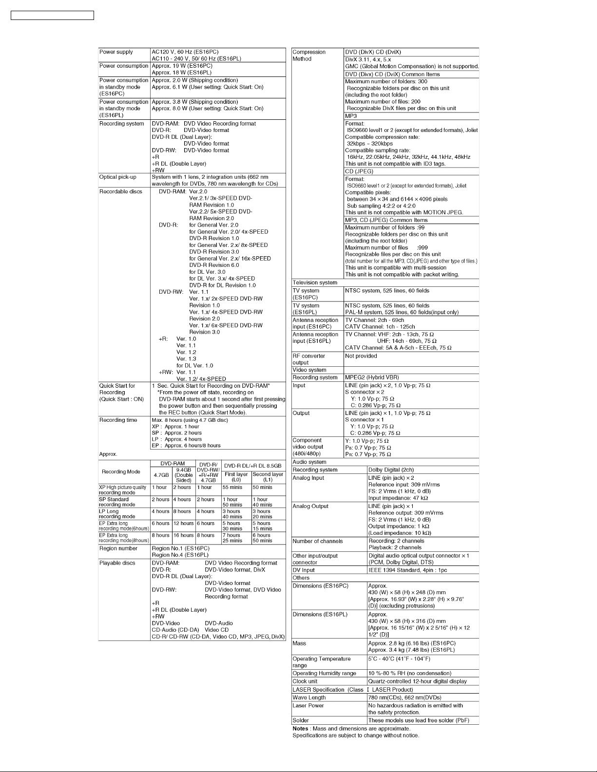
4 Specifications
10
DMR-ES16PC / DMR-ES16PL
5 Feature
5.1. About DivX
5.1.1. General
DivX is a new video compressing format that is applied MPEG4 technology to improve image quality and the compressibility, and
it is developed by the DivXNetworks, Inc., Video file of high resolution and the high picture quality can be made though it is a high
compressibility.
DivX codec is necessary for converting video to DivX file and .playback files made.
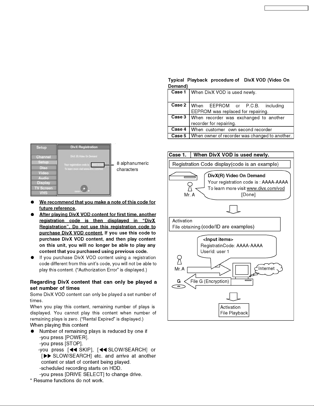
5.1.2. Operating Instructions about DivX
Video-on-Demand Content
DivX Video-on-Demand (VOD) content is encrypted for
copyright protection. In order to play DivX VOD content on this
unit, you first need to register the unit.
Follow the on line instructions for purchasing DivX VOD content
to enter unit´s registration code and register unit. Visit
www.divx.com/vod for more information.
Display unit´s registration code.
11
DMR-ES16PC / DMR-ES16PL
12
DMR-ES16PC / DMR-ES16PL
13
DMR-ES16PC / DMR-ES16PL
14

DMR-ES16PC / DMR-ES16PL
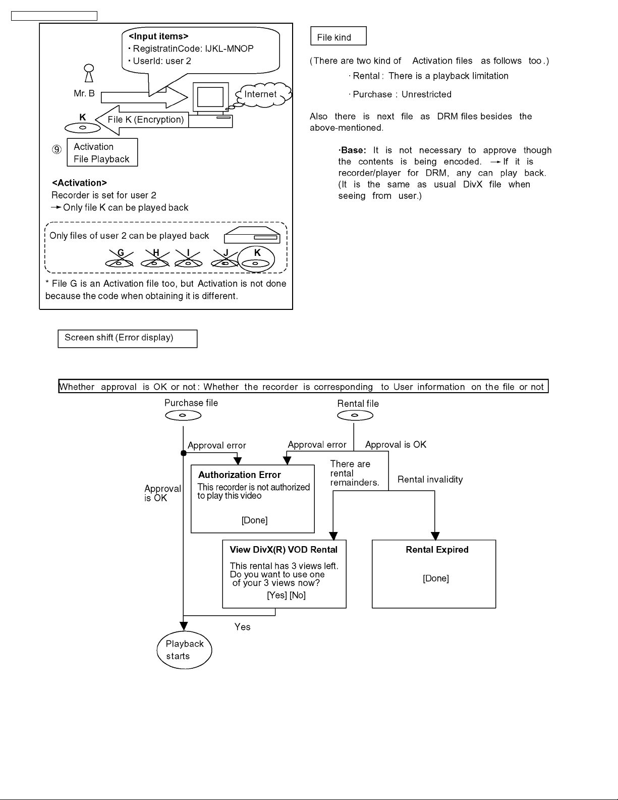
5.1.3. About DivX DRM
Divx file includes file to which DRM(Digital Right Management) is applied and file not applied.
This item is a content that relates only in treating file to which DRM is applied.
1. Registration Code display function
2. User´s registration and approval function
3. Rental management function
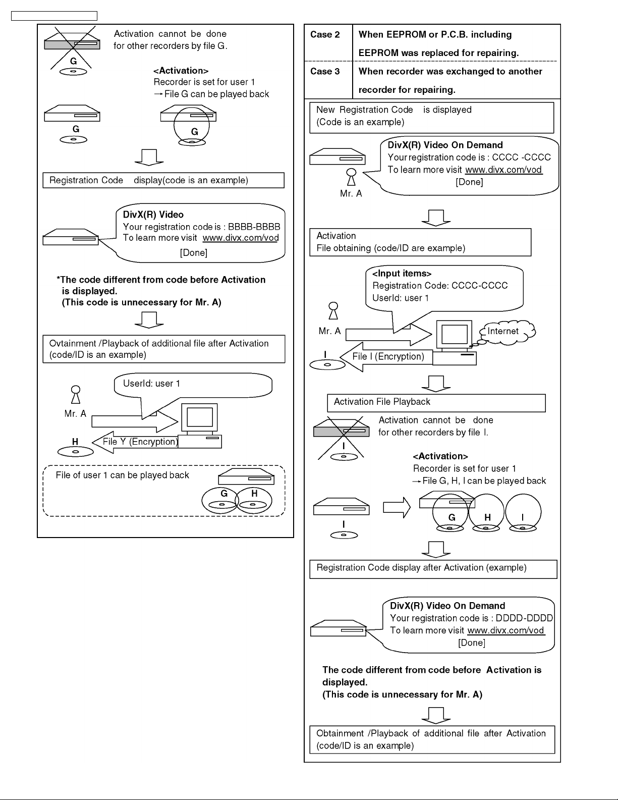
1) Registration Code display function
Registration Code is alphanumeric character sequence 8bytes inputted as recorder information, in case a use purchases or rent
a DivX DRM file in a network.
Registration code is a character sequence generated at random, and differs in each recorder.
Moreover, Registration code is updated by new user authentication ever if same recorder.
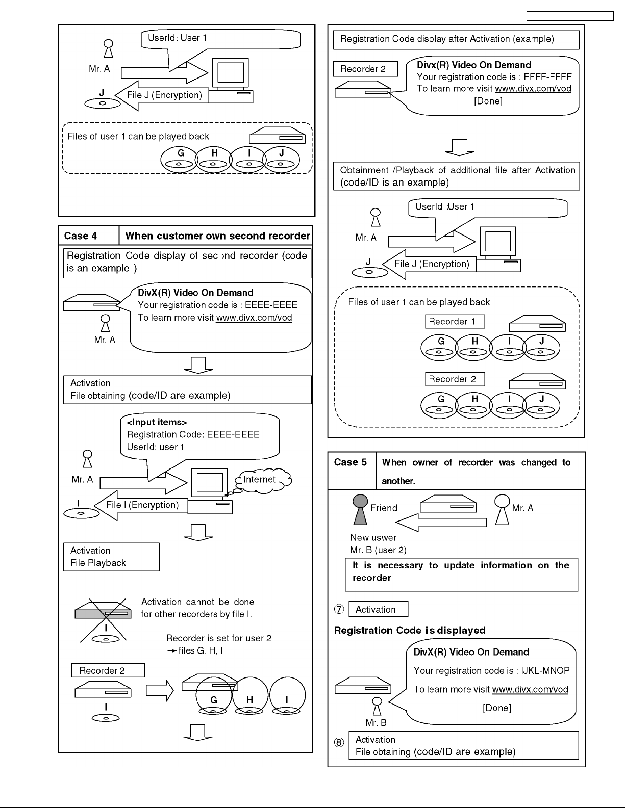
2) User´s registration and approval function
·
· Only one user can register for one recorder. If user´s registration is not done with the recorder, DivX file cannot be played
· ·
back.
·
· User´s registration is performed only when a DivX DRM file is first chosen by recorder
· ·
·
· DivX DRM file that can perform user´s registration is only a file that is registered Registration Code and purchased or rented.
· ·
·
· User authentication is performed whenever DivX DRM file is played back.
· ·
Error message is displayed when failing in user´s registration and approval.
3) Rental management function
There are purchase file without registration of number of playback and rental files with registration of number of playback as
Divx file. Number of playback of rental file is counted by the recorder.
When rental file is played, remaining number of times that can be played back will be shown to users, recorder requests users
to input yes or no.
Following specifications have been installed for the rental files in the purpose to clarify the count condition of number of times
of playback.
·
· Conditions on counting number of times of play.
· ·
1. When a file was opened successfully. (At the time of playback start)
2. When you have done review operation from the start. (Skip to file head)
-
- At this time, remaining number of times that can be played back and confirmation message [Do you play really?] are
- -
displayed.
-
- When the playback point has been skipped to the top of title, number of playback is not counted if the top of title was
- -
not recognized.
-
- Even if the power failure occurs after start of playback of rental file, number of times of playback counted at start of
- -
the playback is held as it is. (Though playback stops by power failure, the number of times of playback is not
counted.)
When it has reached head of title, the playback is ended, and screen becomes DivX menu (There is no resume) and then
cursor is located on title that has been played back.
Then if the same file was continuously played back, it begins to playback from the file head.
Note:
Above mentioned stored user information and number of times of playback are not erased by update of firmware or by
initialization by test mode.
15
DMR-ES16PC / DMR-ES16PL
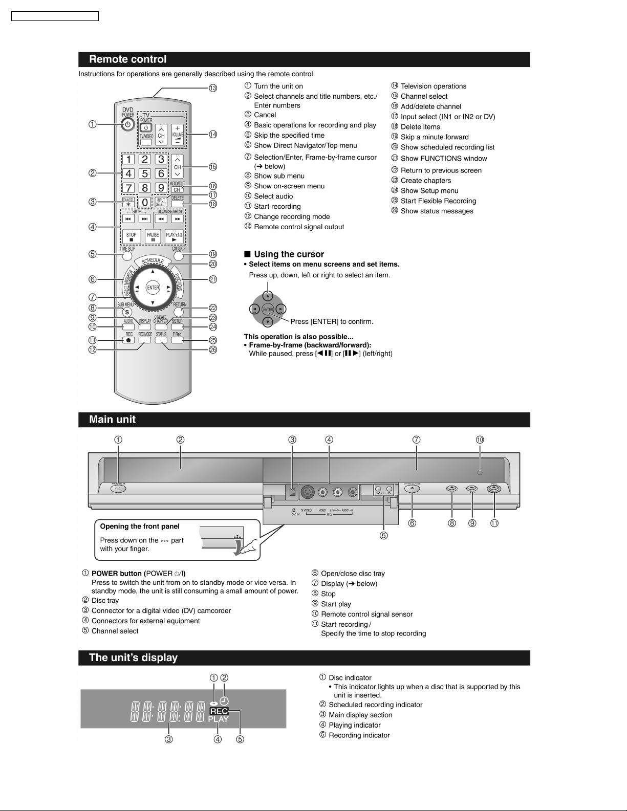
6 Location of Controls and Components
16
DMR-ES16PC / DMR-ES16PL
7 Operation Instructions
7.1. Taking out the Disc from DVD-Drive Unit when the Disc cannot be
ejected by OPEN/CLOSE button
7.1.1. Forcible Disc Eject
7.1.1.1. When the power can be turned off.
1. Turn off the power and press [STOP] [CH UP] keys on the front panel simultaneously for 5 seconds.
7.1.1.2. When the power can not be turned off.
1. Press [POWER] key on the front panel for over 10 seconds to turn off the power forcibly, and press [STOP] [CH UP] keys on
the front panel simultaneously for 5 seconds.
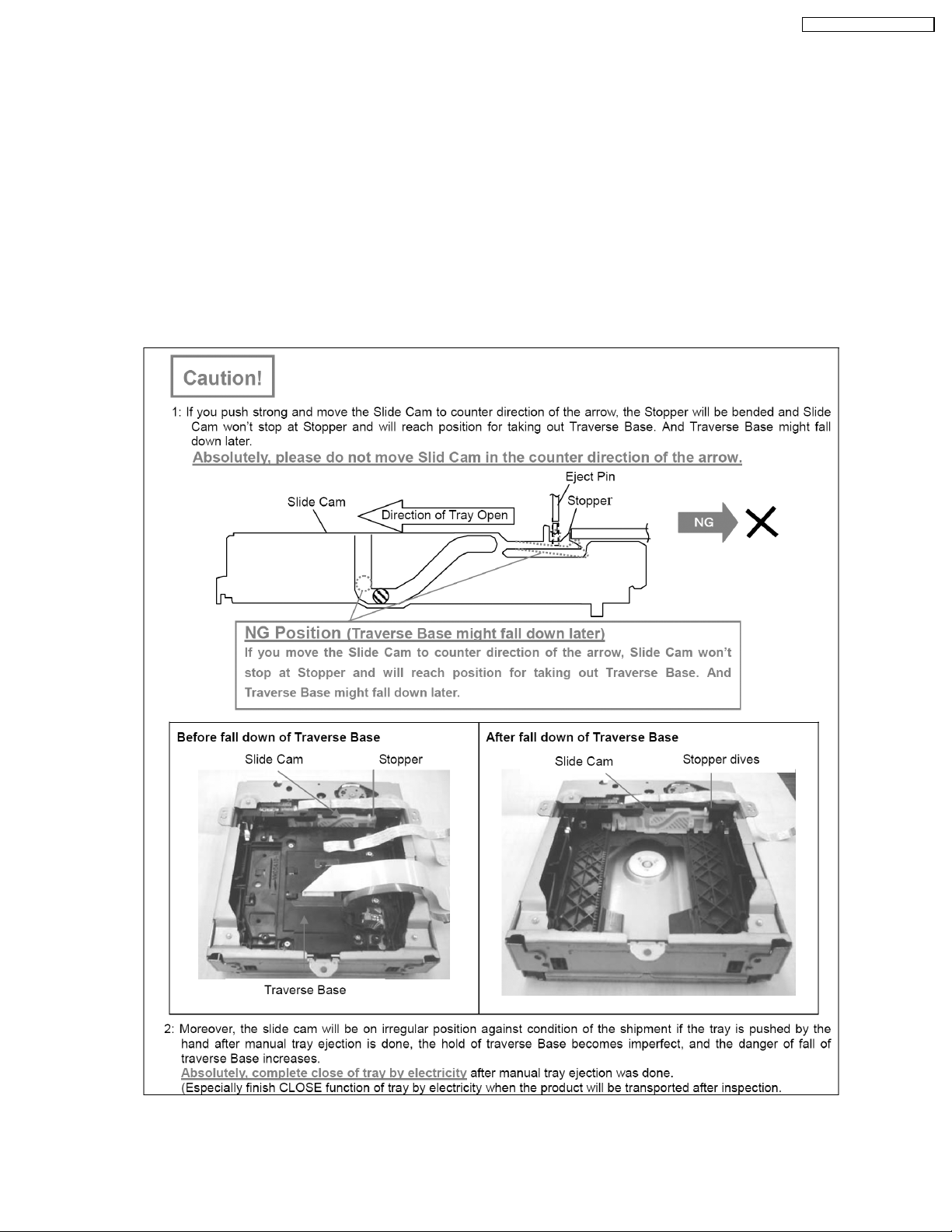
7.1.2. When the Forcible Disc Eject can not be done.
17
DMR-ES16PC / DMR-ES16PL
1. Turn off the power and pull out AC cord.
2. Remove the Top Case.
3. Put deck so that bottom can be seen.
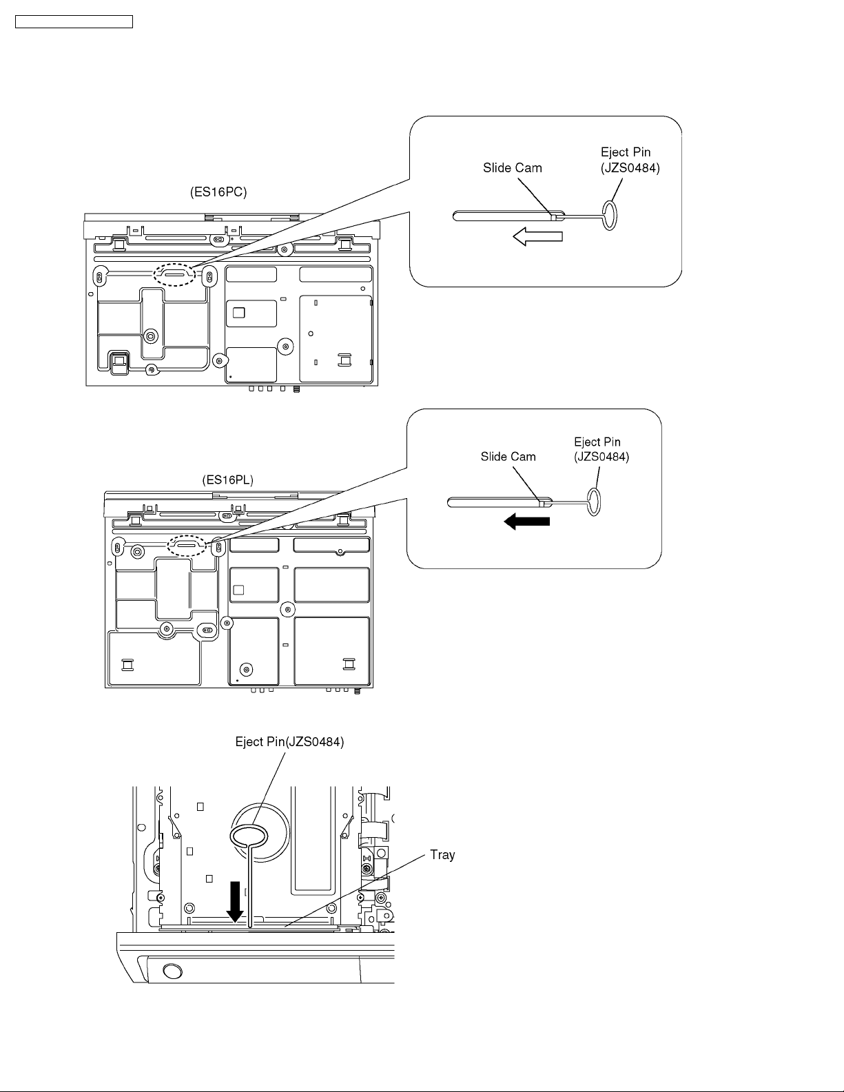
4. Slide SLIDE CAM by Eject Pin (JZJ0484) or minus screw driver (small) in the direction of arrow to eject tray slightly.
5. Put deck upward, and push out Tray by Eject Pin (JZS0484) or minus screw driver (small).
18
DMR-ES16PC / DMR-ES16PL
8 Service Mode
8.1. Self-Diagnosis and Special Mode Setting
8.1.1. Self-Diagnosis Functions
Self-Diagnosis Function provides information for errors to service personnel by “Self-Diagnosis Display” when any error has
occurred.
U**, H** and F** are stored in memory and held.
You can check latest error code by transmitting [0] [1] of Remote Controller in Service Mode.
Automatic Display on FL will be cancelled when the power is turned off or AC input is turned off during self-diagnosis display is ON.
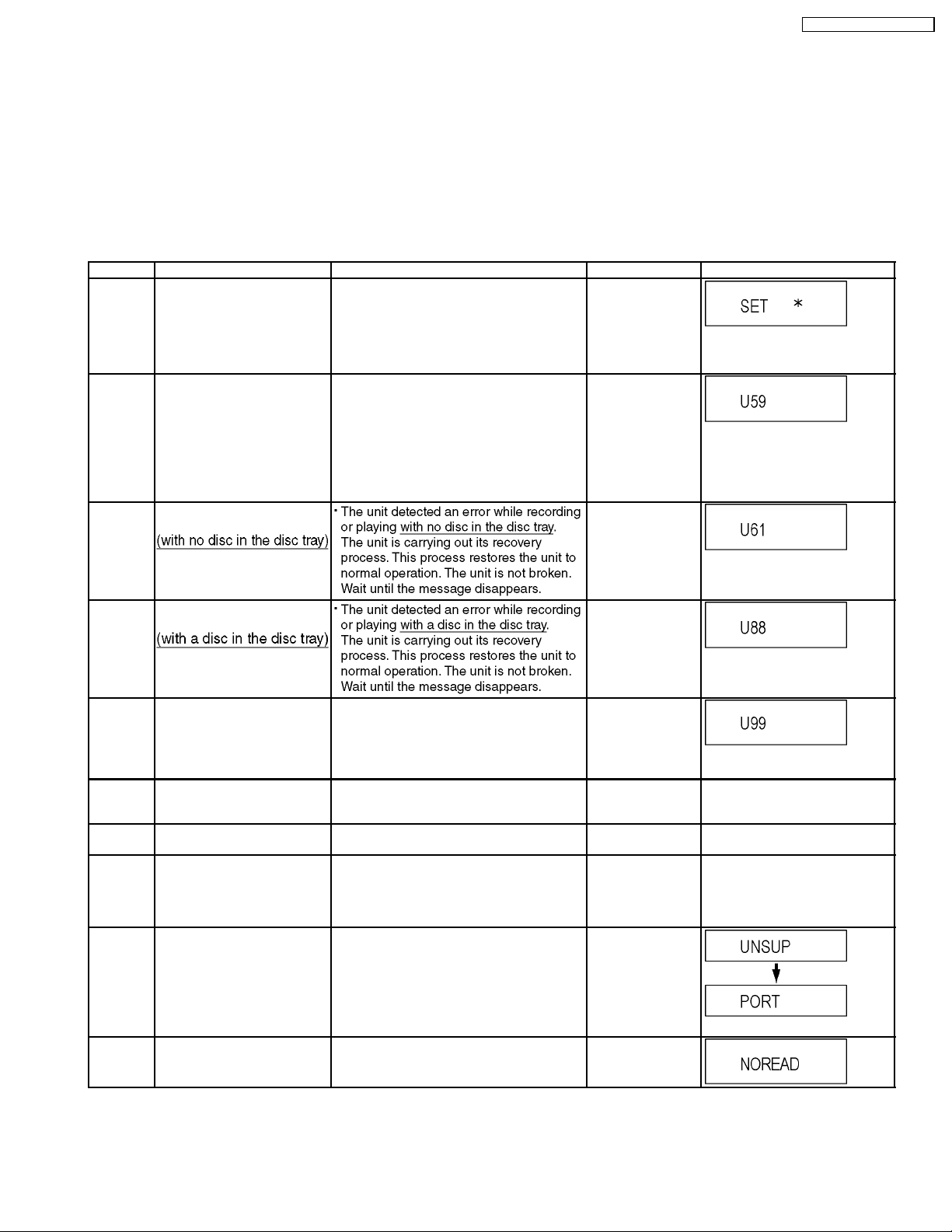
Error Code Diagnosis contents Description Monitor Display Automatic FL display
U30 Remote control code error Display appears when main unit and remote
U59 Abnormal inner temperature
detected
U61 The unit is carrying out its
recovery process.
controller codes are not matched.
Display appears when the drive temperature
exceeds 70°C.
The power is turned off forcibly.
For 30 minutes after this, all key entries are
disabled. (Fan motor operates at the highest
speed for the first 5 minutes. For the
remaining 25 minutes, fan motor is also
stopped.) The event is saved in memory as
well.
No display
“*” is remote controller code of the
main unit.
Display for 5 seconds.
No display
“U59 is displayed for 30 minutes.
No display
U88 The unit is carrying out its
U99 Hang-up Displayed when communication error has
F00 No error information Initial setting for error code in memory
F58 Drive hardware error When drive unit error is detected, the event is
F34 Initialization error when main
UNSUPPORTUnsupported disc error *An unsupported format disc was played,
NO READ Disc read error *A disc is flawed or dirty.
recovery process.
microprocessor is started up
for program recording
occurred between Main microprocessor and
Timer microprocessor.
(Error code Initialization is possible with error
code initialization and main unit initialization.)
saved in memory.
When initialization error is detected after
starting up main microprocessor for program
recording, the power is turned off
automatically.
The event is saved in memory.
although the drive starts normally.
*The data format is not supported, although
the media type is supported.
*Exceptionally in case of the disc is dirty.
*A poor quality failed to start.
*The track information could not be read.
No display
No display
Displayed is left until the
[POWER] key is pressed.
No display No display
No display No display
No display No display
“This disc is
incompatible.”
Display for 5 seconds.
“Cannot read.
Please check the
disc.”
19
DMR-ES16PC / DMR-ES16PL
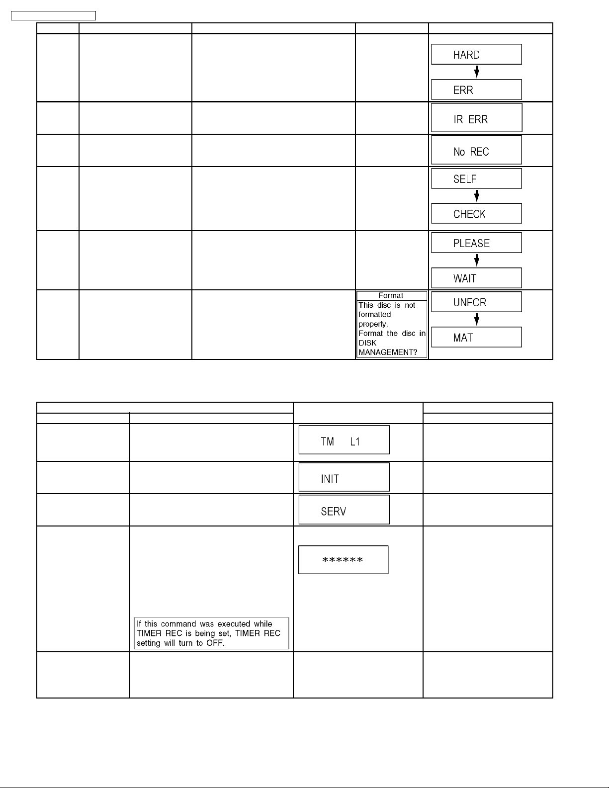
Error Code Diagnosis contents Description Monitor Display Automatic FL display
HARD
ERR
Drive error The drive detected a hard error. “DVD drive error.” Display for 5 seconds.
IR ERR IR communication error [IR ERR] is displayed when communication
No REC Recording is impossible [No REC] is displayed when recording is
SELF
CHECK
PLEASE
WAIT
UNFORMATUnformatted disc error You have inserted an unformatted DVD-RAM
Restoration operation Since the power cord fell out during a power
Unit is in termination process Unit is in termination process now.
between Timer microprocessor and IR
microprocessor fails.
impossible due to the defect, dirt or wound of
media.
failure or operation, it is under restoration
operation.
*It will OK, if a display disappears
automatically. If a display does not disappear,
there is the possibility that defective Digital
P.C.B. / RAM drive.
“BYE” is displayed and power will be turned
off.
In case “Quick Start” of setup menu is ON, it
is displayed in restoration operation for AC
off.
or DVD-RW that is unformatted or recorded
on other equipment.
8.1.2. Special Modes Setting
No display
No display
No display
No display
Item FL display Key operation
Mode name Description Front Key
TEST Mode *All the main unit´s parameters (include tuner)
are initialized.
Rating password The audiovisual level setting password is
initialized to “Level 8”.
Service Mode Setting every kind of modes for servicing.
*Details are described in “8.1.3. Service
Mode at a glance”.
Forced disc eject Removing a disc that cannot be ejected.
The tray will open and unit will shift to P-off
mode.
*When Timer REC is ON or EXT-LINK is ON,
execute " Forced disc eject " after releasing
Timer REC or EXT-LINK.
*This command is not effective during "Child
lock" is ON.
While Demonstration Lock is being set, this
Forced disc eject function is not accepted.
Forced power-off When the power button is not effective while
power is ON, turn off the power forcibly.
*When Timer REC is ON or EXT-LINK is ON,
execute “Forced Power-off” after releasing
Timer REC or EXT-LINK.
The display before execution
leaves.
Display in P-off mode. Press [Power] key over than 10
Press [STOP], [CH UP] and
[OPEN/CLOSE] keys
simultaneously for five seconds
when power is off.
Open the tray, and press [REC] and
[PLAY] simultaneously for 5
seconds.
When the power is off, press [CH
UP], [OPEN/CLOSE] and [REC]
keys simultaneously for 5 seconds.
When the power is off, press
[STOP] and [CH UP] keys
simultaneously for 5 seconds.
seconds.
20
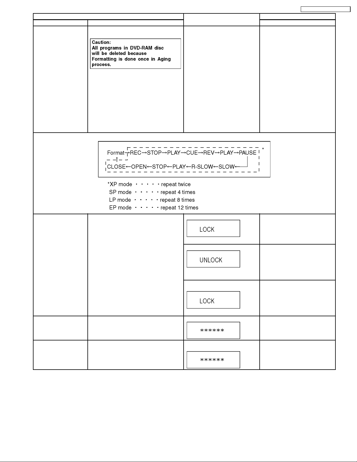
Item FL display Key operation
Mode name Description Front Key
Aging Perform sequence of modes as * Aging
Description shown below continually.
Display following the then mode. When the power is ON, press
[STOP], [POWER] and
[OPEN/CLOSE] simultaneously for
over 5 seconds and less than 10
seconds.
NOTE1:
If Unit has not turned into Aging
mode by operations shown above,
execute TEST MODE once and reexecute operation shown above.
(*All the main unit’s parameters
include tuner are initialized by TEST
mode.)
NOTE2:
If the unit has hung-up because of
pressing keys for over 10 seconds,
once turn off the power, and reexecute this command.
*When releasing Aging mode, press
[POWER] key.
Aging Contents (Example):
DMR-ES16PC / DMR-ES16PL
Demonstration
lock/unlock
ATP Initialization ATP setting is initialized, and the unit turns off
Progressive initialization The progressive setting is initialized to
Ejection of the disc is prohibited.
The lock setting is effective until unlocking the
tray and not released by “Main unit
initialization” of service mode.
automatically.
Interlace.
*When lock the tray.
“LOCK” is displayed for 3 seconds.
*When unlock the tray.
“UNLOCK” is displayed for 3
seconds.
*When press OPEN/CLOSE key
while the tray being locked.
Display “LOCK” for 3 seconds.
It is same with display in stop mode. When the power is on (E-E mode),
The display before execution
leaves.
When the power is on, press
[STOP] and [POWER] keys
simultaneously for 5 seconds.
When the power is on, press
[STOP] and [POWER] keys
simultaneously for 5 seconds.
Press [OPEN/CLOSE] key while the
tray being locked.
press [CH UP] and [CH DOWN]
simultaneously for 5 seconds.
When the power is on (E-E mode),
press [STOP ] and [PLAY]
simultaneously for 5 seconds.
21
DMR-ES16PC / DMR-ES16PL
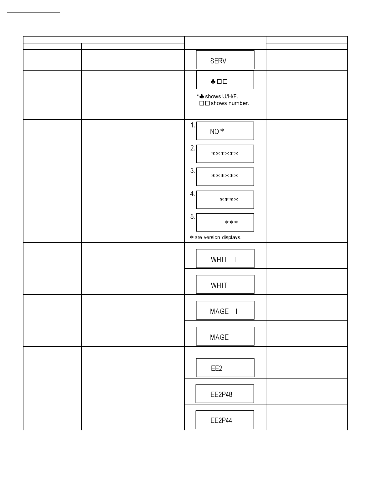
8.1.3. Service Modes at a glance
Service mode setting: While the power is off, press REC, CH UP and OPEN / CLOSE simultaneously for five seconds.
Item FL display Key operation
Mode name Description (Remote controller key)
Release Items Item of Service Mode executing is cancelled. Press [0] [0] or [Return] in service
mode.
Error Code Display Last Error Code of U/H/F held by Timer is
displayed on FL.
*Details are described in “8.1.1. Self-
Diagnosis Functions”.
ROM Version Display 1. Region code (displayed for 5 sec.)
2. Main firm version (displayed for 5 sec.)
3. Timer firm version (displayed for 5 sec.)
4. Drive firm version (displayed for 5 sec.)
5. ROM correction version (left displayed)
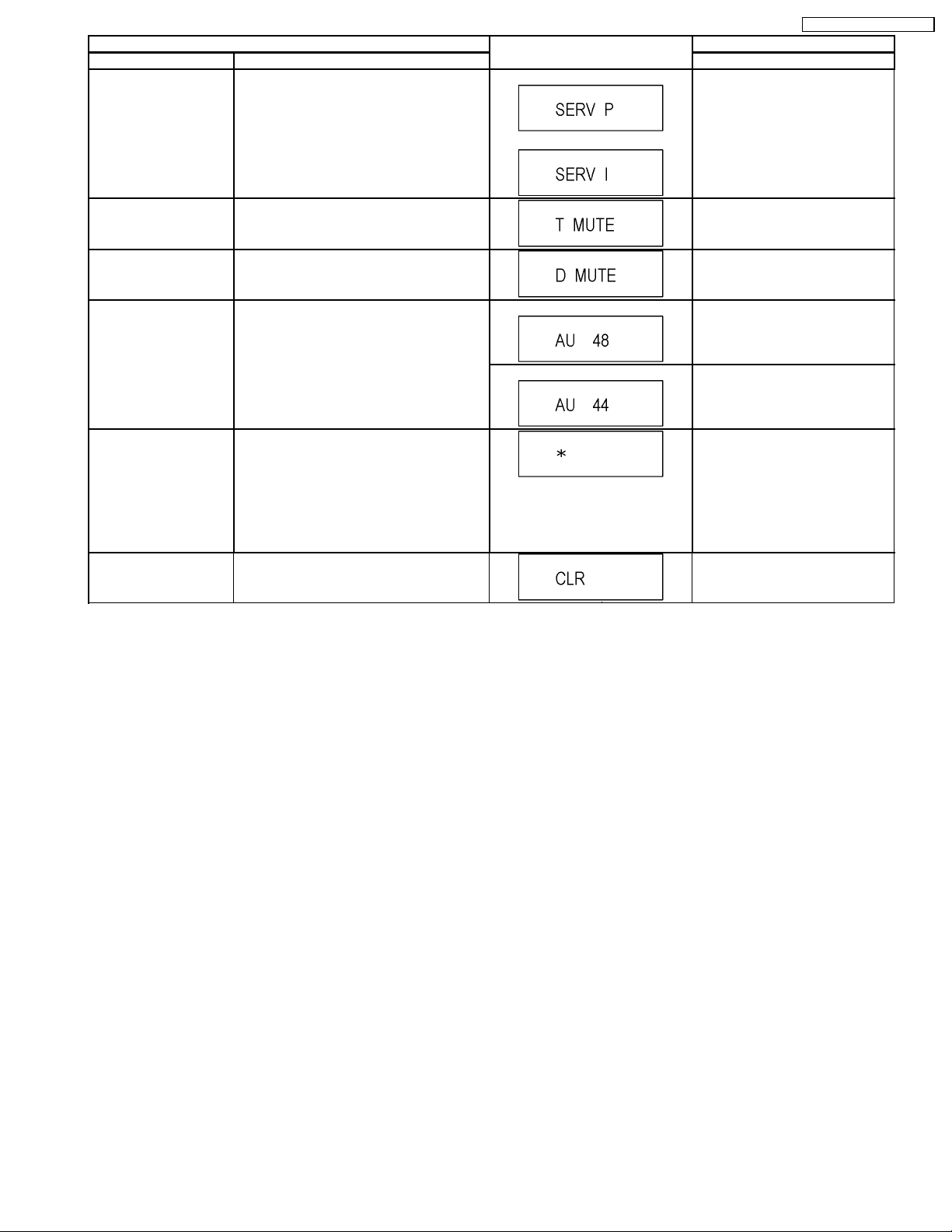
White Picture Output White picture is output as component Output
from AV Decoder.
*White picture
(Saturation rate : 100%)
*It is enable to switch Interlace/Progressive by
“I/P switch: [1] [4]”
Press [0] [1] in service mode
If any error history does not exist,
[F00] is displayed.
Press [0] [2] in service mode
*Initial mode is “Interlace”. Press [1] [1] in service mode.
Switch Interlace/Progressive Press [1] [4] in White Picture Output
mode.
*I/P are switched alternately.
Magenta Picture Output Magenta picture is output with Component
RTSC Return in XP
(A & V)
Output from AV Decoder.
*Magenta picture
(Saturation rate: 100%)
*It is enable to switch Interlace/Progressive by
“I/P switch: [1] [4]”
L1 input signal is encoded (XP), decoded
(XP) and output decoded signal to external
without DISC recording and DISC playback.
*Initial mode is “Interlace”. Press [1] [2] in service mode.
Switch Interlace/Progressive Press [1] [4] in Magenta Picture
Initial mode: EE2/ Interlace/ XP/
Audio 48kHz
Switch Interlace/Progressive Press [1] [4] in RTSC Return XP
Audio 44.1 kHz/ 48 kHz Switch Press [2] [4] in RTSC Return XP
Output mode.
*I/P are switched alternately.
Press [1] [3] in service mode.
mode.
*I/P are switched alternately.
mode.
*48 kHz / 44.1 kHz are switched
alternately.
22
Item FL display Key operation
Mode name Description (Remote controller key)
I/P Switch Switch Interlace and Progressive in EE mode.
*Initial setting is “Interlace”.
Initial mode is Interlace
Press [1] [4] in I/P Switch mode.
*I/P are switched alternately.
*This command is effective during executing
“White Picture Output”, “Magenta Picture
Output” and “RTSC Return in XP (A & V)”
modes.
Switch Interlace/Progressive
DMR-ES16PC / DMR-ES16PL
Audio Mute (XTMUTE) Check whether mute is applied normally by
the timer microprocessor.
Audio Mute (XDMUTE) Check whether mute is applied normally by
the Digital P.C.B..
Audio Pattern Output The audio pattern stored in the internal
memory is output
(Lch: 1kHz/-18dB)
(Rch: 400Hz/-18dB)
*Audio sound clock switching operation of
DAC can be confirmed by sub command [2]
[4].
Laser Used Time
Check laser used time (hours) of drive.
Indiction
Delete the Laser Used
Time
Laser used time stored in the memory of the
unit is deleted.
Press [2] [1] in service mode.
Press [2] [2] in service mode.
Initial mode (Audio 48kHz) Press [2] [3] in service mode.
Audio 44.1kHz/48kHz switching Press [2] [4] in Audio Pattern Output
mode.
*48 kHz / 44.1 kHz are switched
alternately.
Press [4] [1] in service mode.
l(*****) is the used time display in
hour.
lLaser used time of DVD/ CD in
Playback/Recording mode is
counted.
Press [9] [5] in service mode.
23
DMR-ES16PC / DMR-ES16PL
Item FL display Key operation
Mode name Description (Remote controller key)
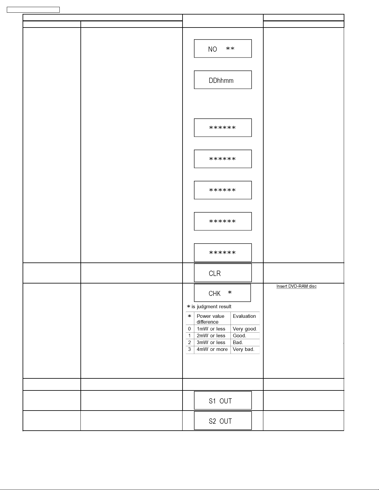
RAM Drive Last Error RAM Drive error code display.
*For details about the drive error code, refer
to the Service Manual for the specific RAM
Drive.
1. Error Number is displayed for 5
seconds.
2. Time when the error has occurred
is displayed for 5 seconds.
DD: Day
hh: Hour
mm: Minute
3. Last Drive Error (1/2) is displayed
for 5 seconds.
4. Last Drive Error (2/2) is displayed
for 5 seconds.
5. Error occurring Disc type is
displayed for 5 seconds.
Press [4] [2] in service mode.
When “INFO******” is being
displayed, past 19 error histories
can be displayed by pressing [0] [1]
- [1] [9]
Delete the Last Drive
Error
Delete the Last Drive Error information stored
on the DVD RAM-Drive.
Laser power confirmation Drive state is judged based on difference
between laser power value at shipping and
present laser power value.
Turn on all FL/LEDs All segments of FL and all LEDs are turned
on.
S1 signal output Forcibly superimpose the S1 signal (approx.
4.5V DC) on the EE chroma signal, and check
the output on the S terminal.
S2 signal output Forcibly superimpose the S2 signal (approx.
2V DC) on the EE chroma signal, and check
the output on the S terminal.
6. Disc Maker ID is displayed for 5
seconds.
In case that the maker cannot be
identified, display is black out.
7. Factor of Drive Error occurring is
left displayed
Press [9] [6] in service mode.
1. into RAM
Drive in service mode. (Other
media are assumed to be noncorrespondence.)
2. Press [4] [4].
If DVD-RAM disc in not inserted,
[NO DISC] is displayed.
If power value study was filed,
[ERROR] is displayed.
All segments are turned on. Press [5] [1] in service mode.
Press [5] [2] in service mode.
Press [5] [3] in service mode.
24
Item FL display Key operation
Mode name Description (Remote controller key)
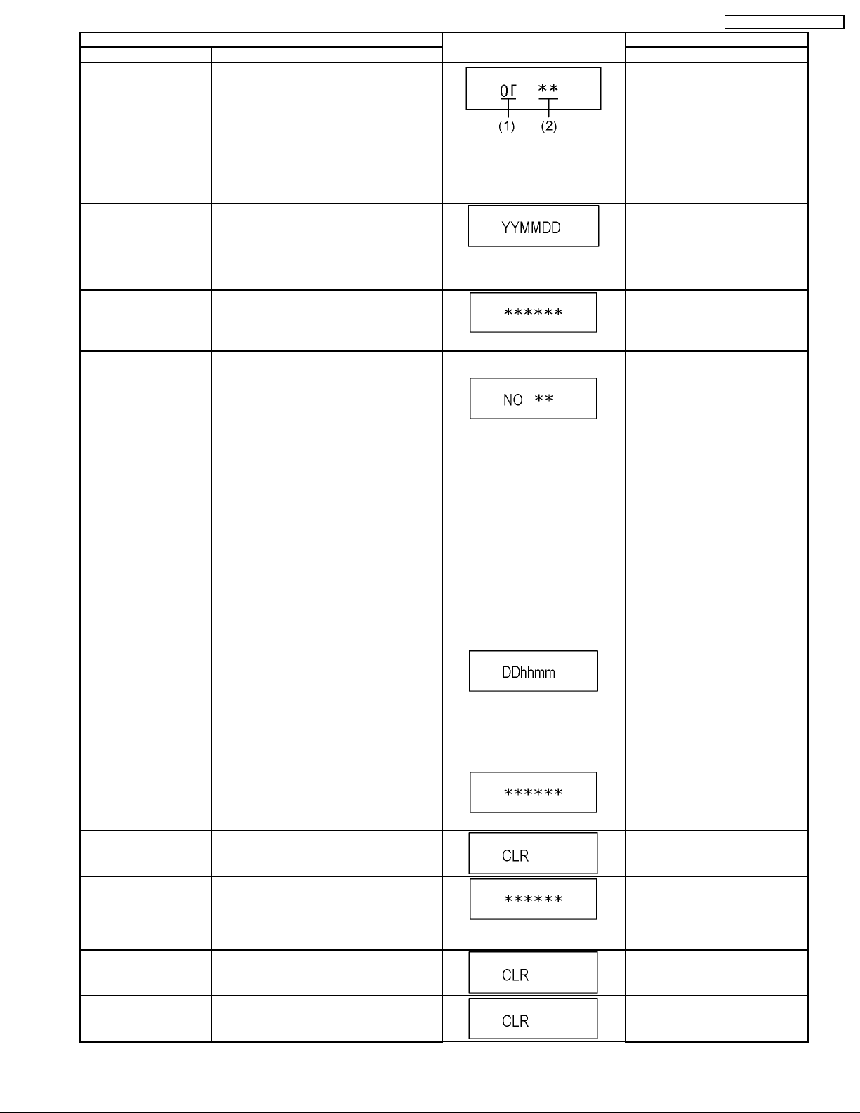
Front connection
inspection
Press all front keys and check the connection
between Main P.C.B. and Front key Switches.
Press [5] [4] in service mode.
(1) Each time a key is pressed,
segment turned on increases one
by one.
(2) Total number of keys that have
been pressed.
Production Date Display Display the date when the unit was produced.
Press [6] [1] in service mode.
YY: Year
MM: Month
DD: Day
Display the accumlated
Display the accumulated unit´s working time.
Press [6] [4] in service mode.
working time
(Indicating unit: Second)
Display the Error History Display the Error History stored on the unit. Display reason of error for 5
seconds.
Press [6] [5] in service mode.
Then press [0] [1] ~ [1] [9], the past
19 error histories are displayed.
DMR-ES16PC / DMR-ES16PL
Delete the Error History Delete Error History information stored on the
unit.
01:
Defect of Digital P.C.B.
(AV DEC / MAIN CPU)
02:
Defect of RAM Drive.
03:
Defect of Disc.
04:
Defect of Digital P.C.B. or
Communication Error.
05:
Defect of Digital P.C.B.
(AV DEC / MAIN CPU)
06:
Defect of HDD.
Display the time when the error has
occurred for 5 seconds.
DD: Day
hh: Hour
mm: Minute
Accumulated working time till
occuring of the error is left
displayed.
(Indicating unit: Second)
Press [9] [7] in service mode.
Tray OPEN/CLOSE Test The RAM drive tray is opened and closed
repeatedly.
Error code initialization Initialization of the last error code held by
timer (Write in F00)
Initialize Service Last Drive Error, Error history and Error
Codes stored on the unit are initialized to
factory setting.
“*” is number of open/close cycle
times.
25
Press [9] [1] in service mode
*When releasing this mode, press
the [POWER] button of Remote
Controller more than 10 seconds.
Press [9] [8] in service mode.
Press [9] [9] in service mode.

DMR-ES16PC / DMR-ES16PL
Item FL display Key operation
Mode name Description (Remote controller key)
Finishing service mode Release Service Mode. Display in STOP (E-E) mode. Press power button on the front
panel or Remote controller in
service mode.
26

9 Service Fixture & Tools
Part Number Description Compatibility
RFKZ0365 Extension Cable (MainP.C.B. - Digital P.C.B. / 64 Pin) Same as ES15 Series
JZS0484 Eject Pin Same as E50 Series
RFKZ03D01K Lead Free Solder (0.3mm/100g Reel) Same as ES15 Series
RFKZ06D01K Lead Free Solder (0.6mm/100g Reel) Same as ES15 Series
RFKZ10D01K Lead Free Solder (1.0mm/100g Reel)) Same as ES15 Series
RFKZ0316 Solder Remover (Lead free low temperature Solder/50g) Same as ES15 Series
RFKZ0328 Flux Same as ES15 Series
RFKZ0329 Bottle of Flux Same as ES15 Series
DMR-ES16PC / DMR-ES16PL
27
DMR-ES16PC / DMR-ES16PL
10 Disassembly and Assembly Instructions
10.1. Disassembly Flow Chart (ES16PC)
The following chart is the procedure for disassembling the casing and inside parts for internal inspection when carrying out the
servicing.
To assemble the unit, reverse the steps shown in the chart below.
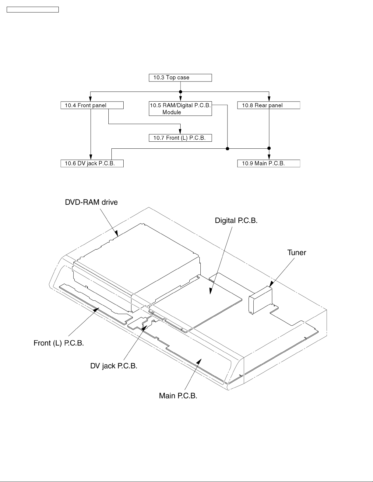
10.2. P.C.B. Positions (ES16PC)
28
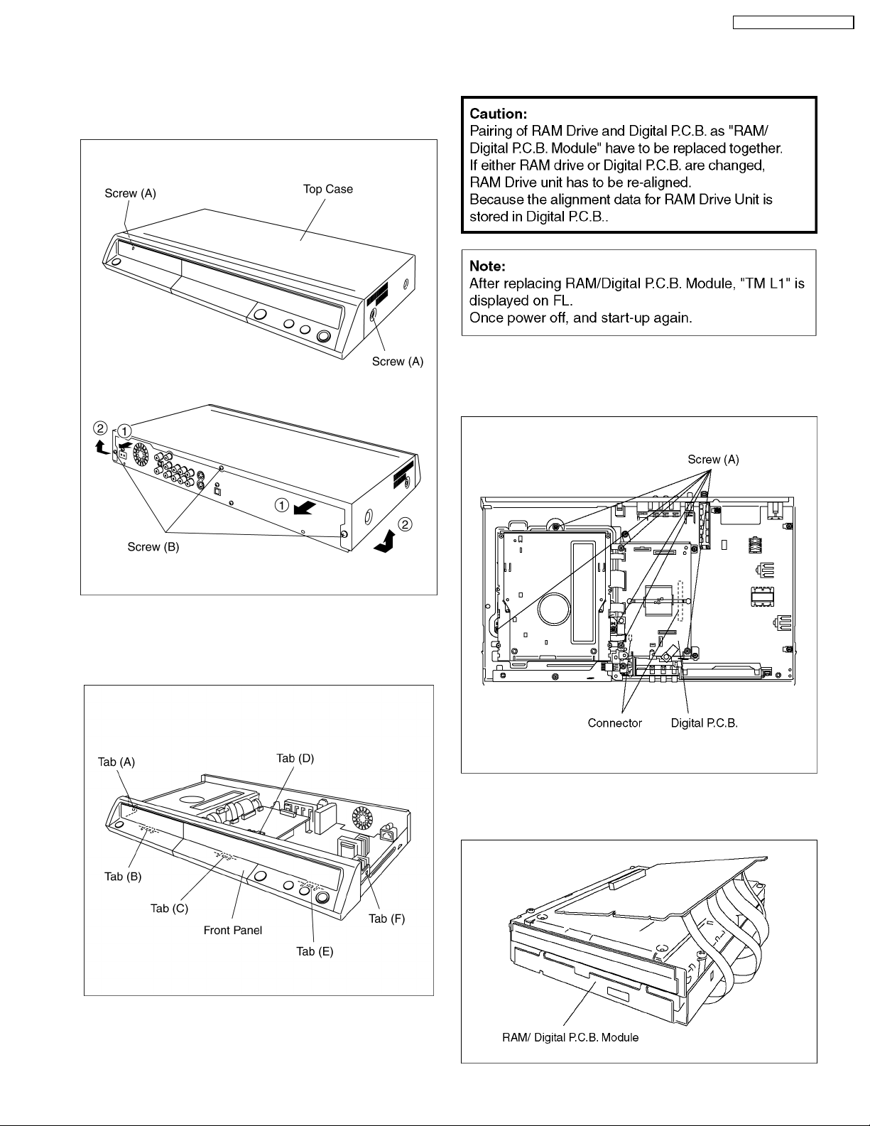
10.3. Top Case (ES16PC)
1. Remove the 2 screws (A) and 3 screws (B).
2. Slide Top Case rearward and open the both ends at rear
side of the Top Case a little and lift the Top Case in the
direction of the arrows.
DMR-ES16PC / DMR-ES16PL
10.5. RAM/Digital P.C.B. Module
(ES16PC)
1. Remove 6 Screws (A).
2. Lift up Digital P.C.B. slightly so to disconnect Connectors to
remove Digital P.C.B.
10.4. Front Panel (ES16PC)
1. Unlock 6 tabs in (A) - (F) turn.
Pull with the front panel in the direction of your side.
3. Put Digital P.C.B. on RAM Drive and remove RAM/Digital
P.C.B. Module.
29
DMR-ES16PC / DMR-ES16PL
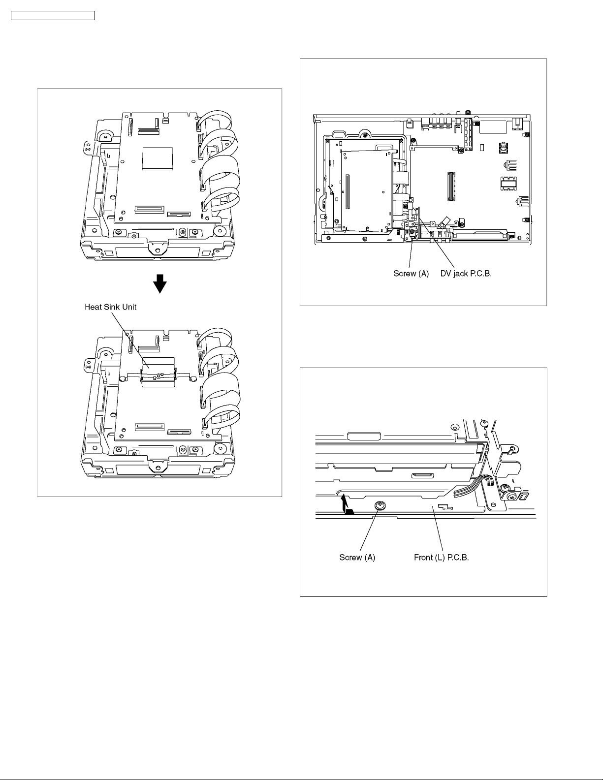
Note:
RAM/Digital P.C.B. Module as service part has no heat sink
unit.
Before returning to customer, heat sink unit should be
installed on Digital P.C.B..
10.6. DV Jack P.C.B. (ES16PC)
1. Remove a Screw (A) to remove DV jack P.C.B.
10.7. Front (L) P.C.B. (ES16PC)
1. Remove a Screw (A) and connector.
2. Front (L) P.C.B. is removed in the direction of the arrow.
30
 Loading...