

Panasonic DMR-BST700EG, DMR-BST701EG, DMR-BST800EG Service Manual
ORDER NO.DSD1107027CE
Blu-ray Disc Recorder
Model No. DMR-BST700EG
DMR-BST701EG
DMR-BST800EG
Vol. 1
Colours
(S)..................Silver Type (Only BST701EG)
(K)..................Black Type (Only BST700EG, BST800EG)
© Panasonic Corporation 2011.
Unauthorized copying and distribution is a violation
of law.

234


TABLE OF CONTENTS
PAGE PAGE
1 Safety Precautions -----------------------------------------------5
1.1. General guidelines-----------------------------------------5
2Warning--------------------------------------------------------------6
2.1. Prevention of Electrostatic Discharge (ESD)
to Electrostatic Sensitive (ES) Devices---------------6
2.2. Precaution of Laser Diode -------------------------------7
2.3. Service caution based on legal restrictions----------8
3 Service Navigation------------------------------------------------9
3.1. How to format for HDD when replacement of
HDD or Main P.C.B. ---------------------------------------9
3.2. Combination of Multiple Pressing on the
Remote Control---------------------------------------------9
3.3. Entering Special Modes with Combination of
Multiple Pressing on the Remote Control---------- 10
3.4. Service Information--------------------------------------11
3.5. Caution for DivX------------------------------------------ 11
3.6. Micro Fuse conducting check------------------------- 13
3.7. (HDD/BD Drive) Service Navigation----------------- 14
3.8. Operation check when a USB device is
connected-------------------------------------------------- 16
3.9. Wi-Fi Module (Internal) Malfunction Check
(Simplified Method)--------------------------------------17
3.10. Check with Tuner Service Mode ---------------------18
4 Specifications----------------------------------------------------23
5 Location of Controls and Components------------------26
6 Installation Instructions---------------------------------------28
6.1. Taking out the Disc from BD-Drive Unit when
the Disc cannot be ejected by OPEN/CLOSE
button--------------------------------------------------------28
7 Service Mode-----------------------------------------------------29
7.1. Self-Diagnosis and Special Mode Setting----------29
8 Service Fixture & Tools---------------------------------------49
9 Disassembly and Assembly Instructions---------------50
9.1. Unit-----------------------------------------------------------50
9.2. BD Drive----------------------------------------------------57
10 Measurements and Adjustments --------------------------64
10.1. Service Positions-----------------------------------------64
10.2. Caution for Replacing Parts ---------------------------69
10.3. Standard Inspection Specifications after
Making Repairs-------------------------------------------70
1 Safety Precautions
1.1. General guidelines
1. When servicing, observe the original lead dress. If a short circuit is found, re place all parts which have been overheated or
damaged by the short circuit.
2. After servicing, see to it that all the protective devices such as insulation barriers, insulation papers shields are properly
installed.
3. After servicing, make the following leakage current checks to prevent the customer from being exposed to shock hazards.
1.1.1. Leakage current cold check
1. Unplug the AC cord and connect a jumper between the
two prongs on the plug.
2. Measure the resistance value, with an ohmmeter,
between the jumpered AC plug and each exposed metallic cabinet part on the equipment such as screwheads,
connectors, control shafts, etc. When the exposed metallic part has a return path to the chassis, the reading
should be between 1MΩ and 5.2MΩ.
When the exposed metal does not have a return path to
the chassis, the reading must be .
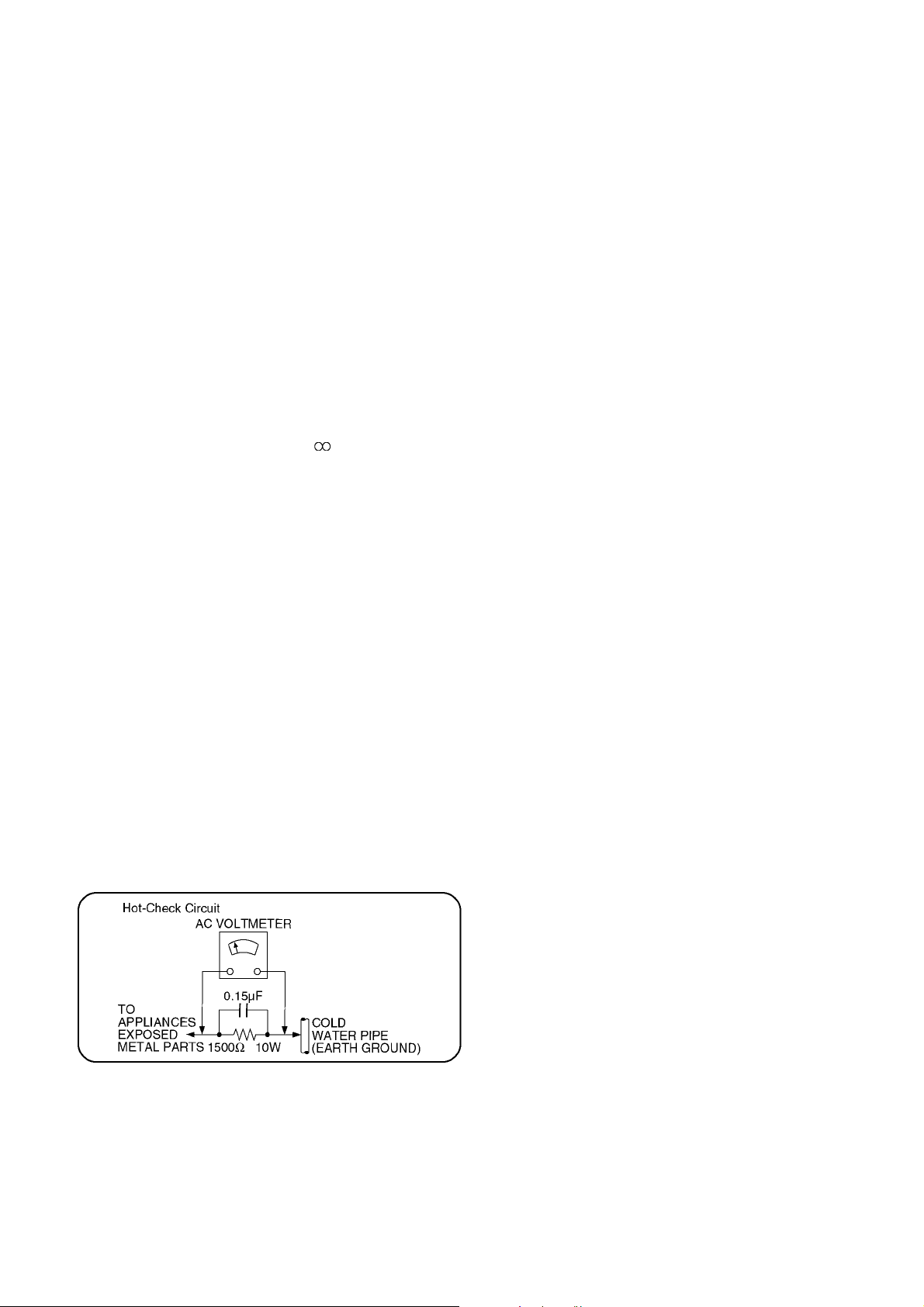
1.1.2. Leakage current hot check
(See Figure 1.)
1. Plug the AC cord directly into the AC outlet. Do not use
an isolation transformer for this check.
2. Connect a 1.5kΩ, 10 watts resistor, in parallel with a
0.15μF capacitors, between each exposed metallic part
on the set and a good earth ground such as a water pipe,
as shown in Figure 1.
3. Use an AC voltmeter, with 1000 ohms/volt or more sensitivity , to measure the potential across the resistor.
4. Check each exposed metallic part, and measure the voltage at each point.
5. Reverse the AC plug in the AC outlet and repeat each of
the above measurements.
6. The potential at any point should not exceed 0.75 volts
RMS. A leakage current tester (Simpson Model 229 or
equivalent) may be used to make the hot checks, leakage
current must not exceed 1/2 milliampere. In case a measurement is outside of the limits specified, there is a possibility of a shock hazard, and the equipment should be
repaired and rechecked before it is returned to the customer.
Figure 1
5
2Warning
2.1. Prevention of Electrostatic Discharge (ESD) to Electrostatic Sensitive
(ES) Devices
Some semiconductor (solid state) devices can be damaged easily by static electricity. Such components commonly are called Electrostatic Sensitive (ES) Devices. Examples of typical ES devices are integrated circuits and some field-effect transistor-sand semiconductor "chip" components. The following techniques should be used to help reduce the incidence of component damage caused
by electrostatic discharge (ESD).
1. Immediately before handling any semiconductor component or semiconductor-equipped assembly, drain off any ESD on your
body by touching a known earth ground. Alternatively, obtain and wear a commercially available discharging ESD wrist strap,
which should be removed for potential shock reasons prior to applying power to the unit under test.
2. After removing an electrical assembly equipped with ES devices, place the assembly on a conductive surface su ch as a luminum foil, to prevent electrostatic charge buildup or exposure of the assembly.
3. Use only a grounded-tip soldering iron to solder or unsolder ES devices.
4. Use only an anti-static solder removal device. Some solder removal devices not classified as "anti-static (ESD protected)" can
generate electrical charge sufficient to damage ES devices.
5. Do not use freon-propelled chemicals. These can generate electrical charges sufficient to damage ES devices.
6. Do not remove a replacement ES device from its protective package until immediately before you are ready to install it. (Most
replacement ES devices are packaged with leads electrically shorted together by conductive foam, aluminum foil or comparable conductive material).
7. Immediately before removing the protective material from the leads of a replacement ES device, touch the protective material
to the chassis or circuit assembly into which the device will be installed.
Caution
Be sure no power is applied to the chassis or circuit, and observe all other safety precautions.
8. Minimize bodily motions when handling unpackaged replacement ES devices. (Otherwise harmless motion such as the
brushing together of your clothes fabric or the lifting of your foot from a carpet ed floor can generate static electricity sufficient
to damage an ES device).
6
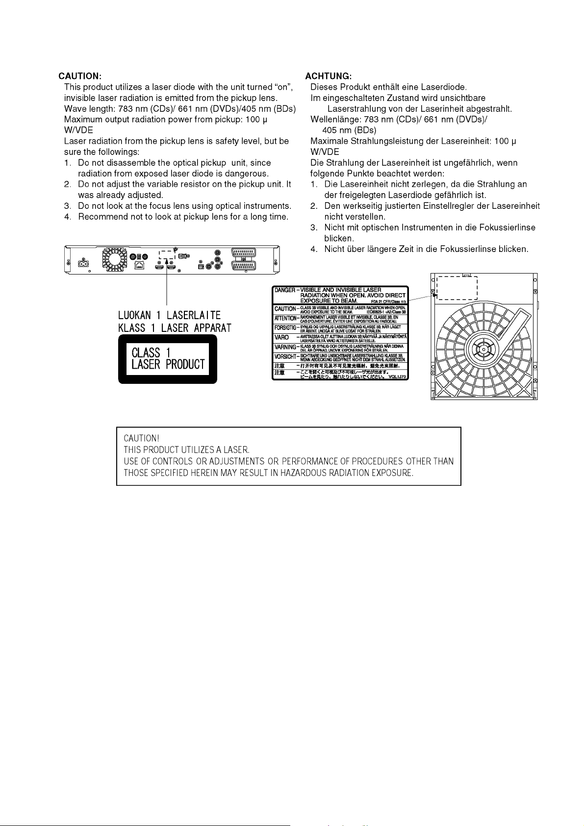
2.2. Precaution of Laser Diode
7

2.3. Service caution based on legal restrictions
2.3.1. General description about Lead Free Solder (PbF)
The lead free solder has been used in the mounting process of all electrical comp onents on the printed circuit boards us ed for this
equipment in considering the globally environmental conservation.
The normal solder is the alloy of tin (Sn) and lead (Pb). On the other hand, the lead free solder is the alloy mainly consists of tin
(Sn), silver (Ag) and Copper (Cu), and the melting point of the lead free solder is higher approx.30 degrees C (86°F) more than that
of the normal solder.
Definition of PCB Lead Free Solder being used
The letter of "PbF" is printed either foil side or components side on the PCB using the lead free solder.
(See right figure)
Service caution for repair work using Lead Free Solder (PbF)
• The lead free solder has to be used when repairing the equipment for which the lead free solder is used.
(Definition: The letter of "PbF" is printed on the PCB using the lead free solder.)
• To put lead free solder, it should be well molten and mixed with the original lead free solder.
• Remove the remaining lead free solder on the PCB cleanly for soldering of the new IC.
• Since the melting point of the lead free solder i s higher than that of the normal lead solder, it takes the longer time to melt the
lead free solder.
• Use the soldering iron (more than 70W) e quipped with the tempe rature control after setting the te mperature at 350±30 degrees
C (662±86°F).
Recommended Lead Free Solder (Service Parts Route.)
• The following 3 types of lead free solder are available through the service parts route.
RFKZ03D01KS-----------(0.3mm 100g Reel)
RFKZ06D01KS-----------(0.6mm 100g Reel)
RFKZ10D01KS-----------(1.0mm 100g Reel)
Note
* Ingredient: tin (Sn), 96.5%, silver (Ag) 3.0%, Copper (Cu) 0.5%, Cobalt (Co) / Germanium (Ge) 0.1 to 0.3%
8
3 Service Navigation
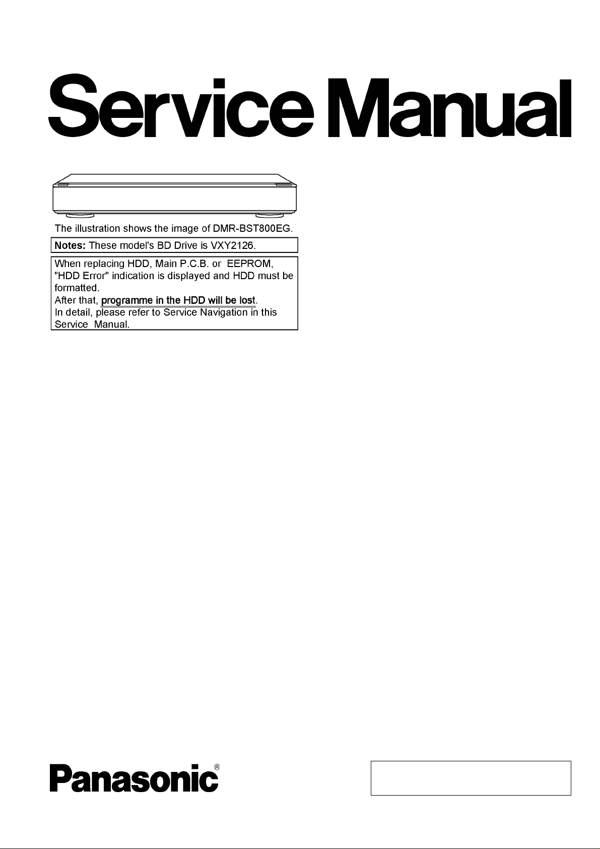
3.1. How to format for HDD when replacement of HDD or Main P.C.B.
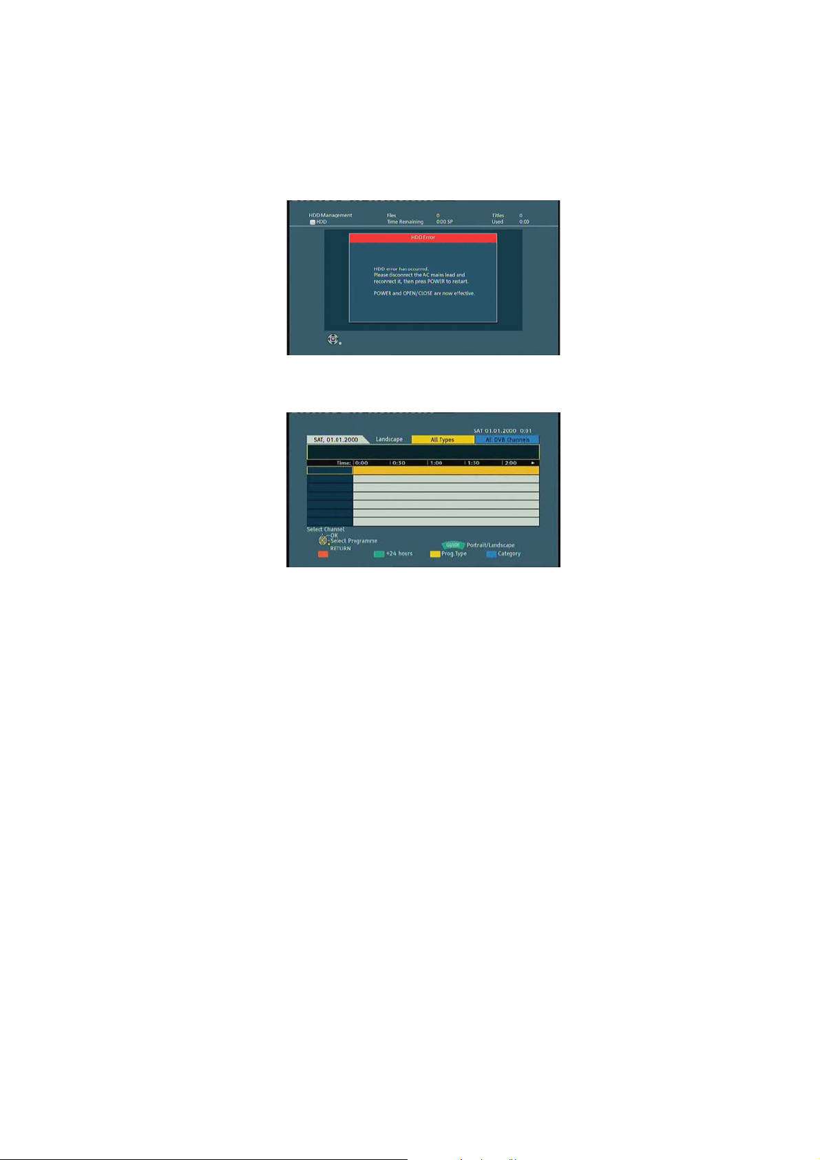
3.1.1. How to escape " HDD Error " indication on GUI display.
1. When exchange HDD or Main P.C.B., the " HDD Error " screen is displayed, but, according to a foll owing procedure, please
format HDD.
2. Press power button to turn off the power first, then turn on the power with the [ GUIDE ] button on remote-controller.
(Shown in Reference screen 1)
(Reference screen 1)
3. Press [ RETURN ] button to move to the normal display.
3.1.2. Procedure of the " HDD format ".
1. Press [FUNCTION MENU].
2. Select " Others " and press [OK].
3. Select " Setup " and press [OK].
4. Select " HDD/Disc " and press [OK].
5. Select " HDD Management " and press [OK] for 3 seconds.
6. Select " Format HDD " and press [OK].
7. Select " Yes " and press [OK].
8. Select " Start " and press [OK]. Then formatting starts.
9. Press [OK] after formatting completed.
10. Press [RETURN] to exit setting mode.
3.2. Combination of Multiple Pressing on the Remote Control
Press multi-buttons (in combination) on the remote control simultaneously for operations, such as initialization or service mode, etc.
There are no multiple pressing functions on the previous remote controls, thus, please be sure to use the supplied remote control.
9
3.3. Entering Special Modes with Combination of Multiple Pressing on the
Remote Control
Enter the following special modes by multiple pressing functions on the supplied remote control.
After entering each mode, switch to the desired menus for operation.
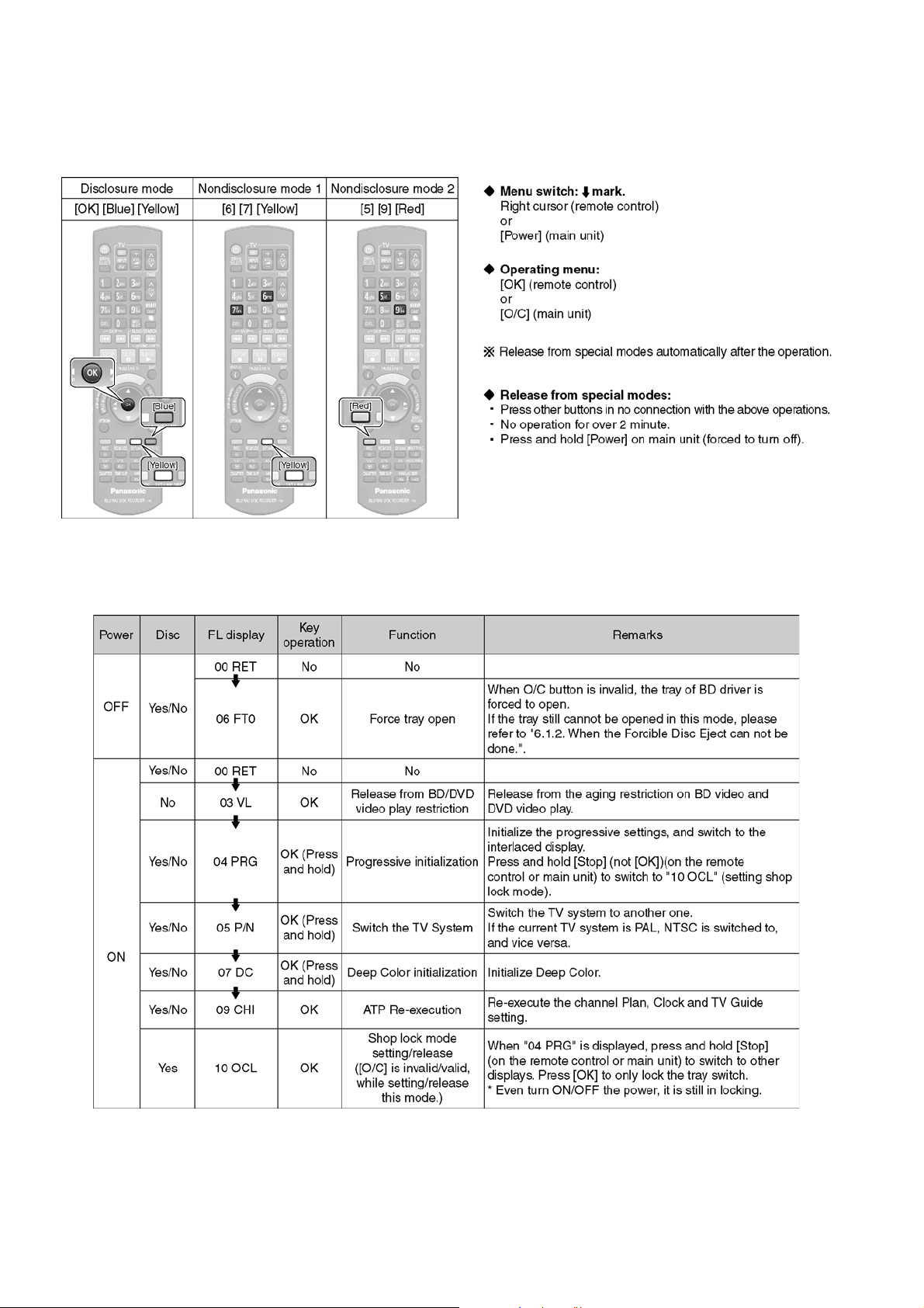
3.3.1. Disclosure mode (Combination of multiple pressing: [OK] [Blue] [Yellow])
Press and hold [OK] [Blue] [Yellow] on the remote control simultaneously for 5 sec., then "00 RET" is displayed on FL display window.
10
3.3.2. Nondisclosure mode 1 (Combination of multiple pressing: [6] [7] [Yellow])
Press and hold [6] [7] [Yellow] on the remote control simultaneously for 5 sec., then "50 RET" is displayed on FL display window.
3.3.3. Nondisclosure mode 2 (Combination of multiple pressing: [5] [9] [Red])
Press and hold [5] [9] [Red] on the remote control simultaneously for about 5 sec., then "70 RET" is displayed on FL display window.
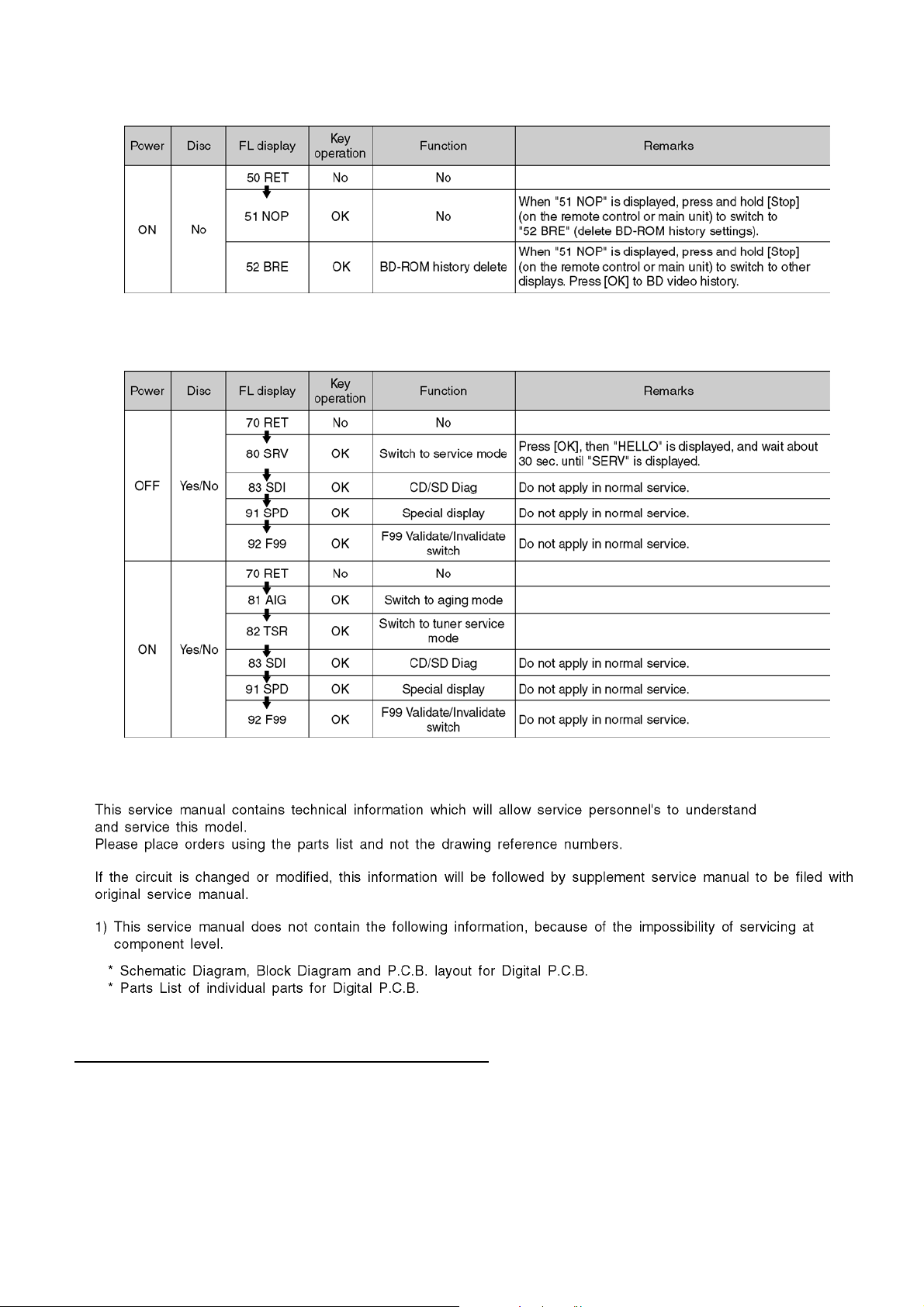
3.4. Service Information
3.5. Caution for DivX
"Warning for Customers Who Use DivX Video-on-Demand content" when replacing the FLASH ROM or EEPROM or P.C.B.
First, copy the Last part of this page for the customers who continue to use DivX Video-on-Demand service.
11

12
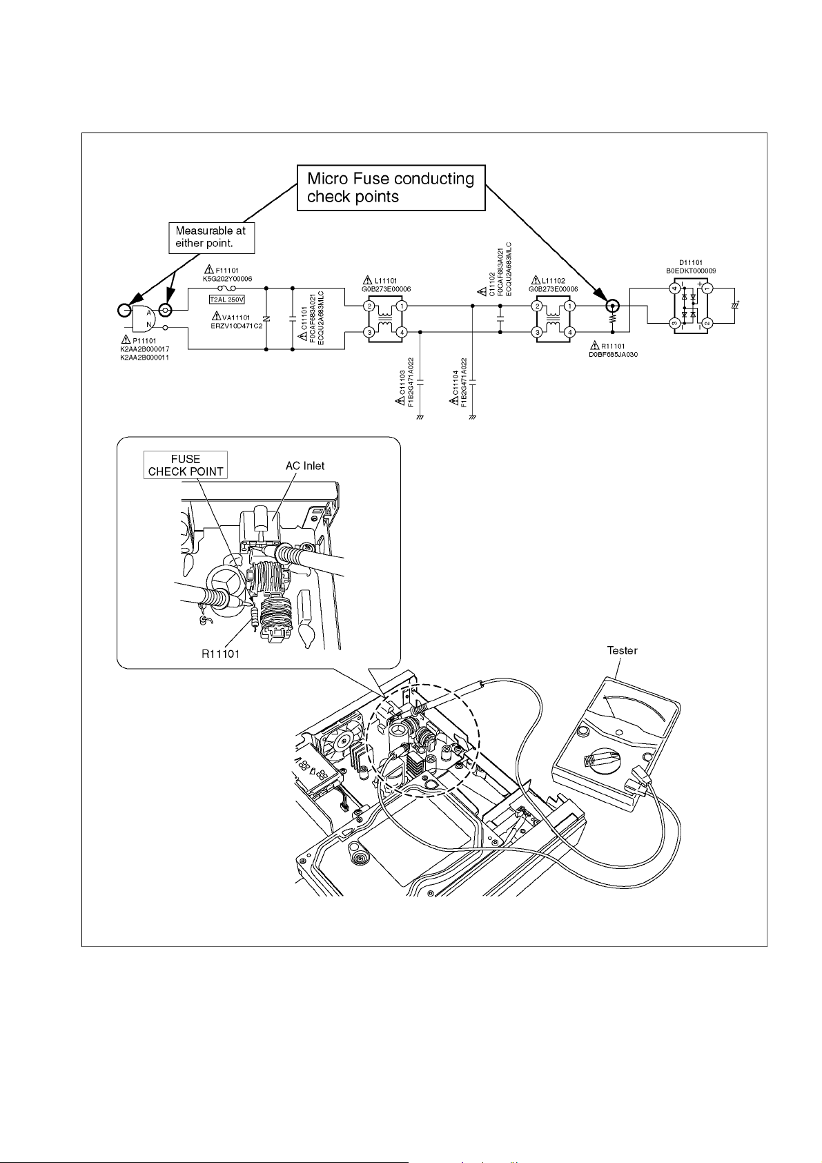
3.6. Micro Fuse conducting check
This unit uses the Micro Fuse.
Check the Micro Fuse conducting using the Tester at the check points below.
13
3.7. (HDD/BD Drive) Service Navigation
3.7.1. HDD/BD Drive Malfunction check (Simplified Method)
Perform simple quality judgement process of HDD/BD Drive according to the following operations.
1. Execute Service Mode
1) Turn the power off.
2) Press the [5] [9] and [RED] button simultaneously for five seconds, then [70 RET] is displayed on FL.
3) Press the [ ] button to select until [80 SRV] is displayed on FL.
4) Press the [OK] button.
5) It is displayed on FL as [HELLO-->SERV].: It is shown to have entered the service mode.
2. Press [3] [8] of remote controller keys in service mode.
3. Judge the quality on FL display.
14
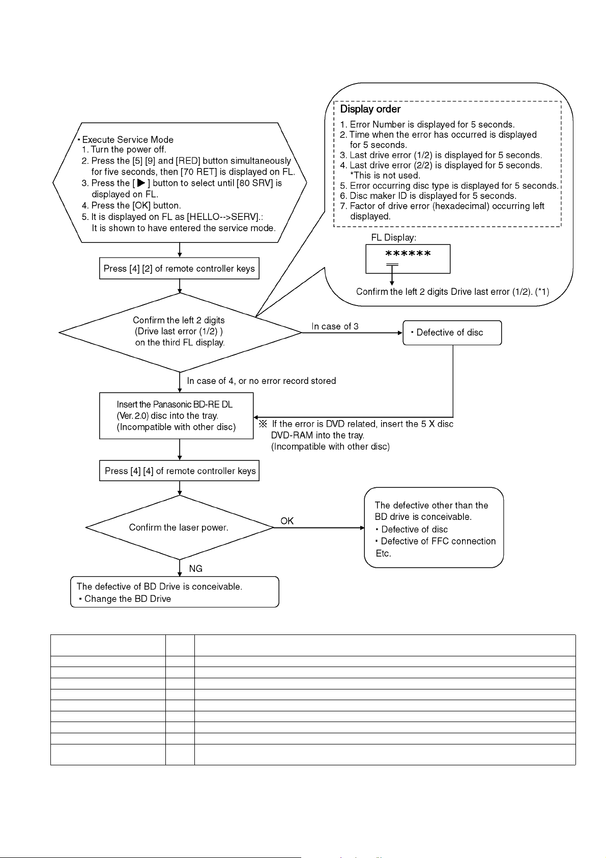
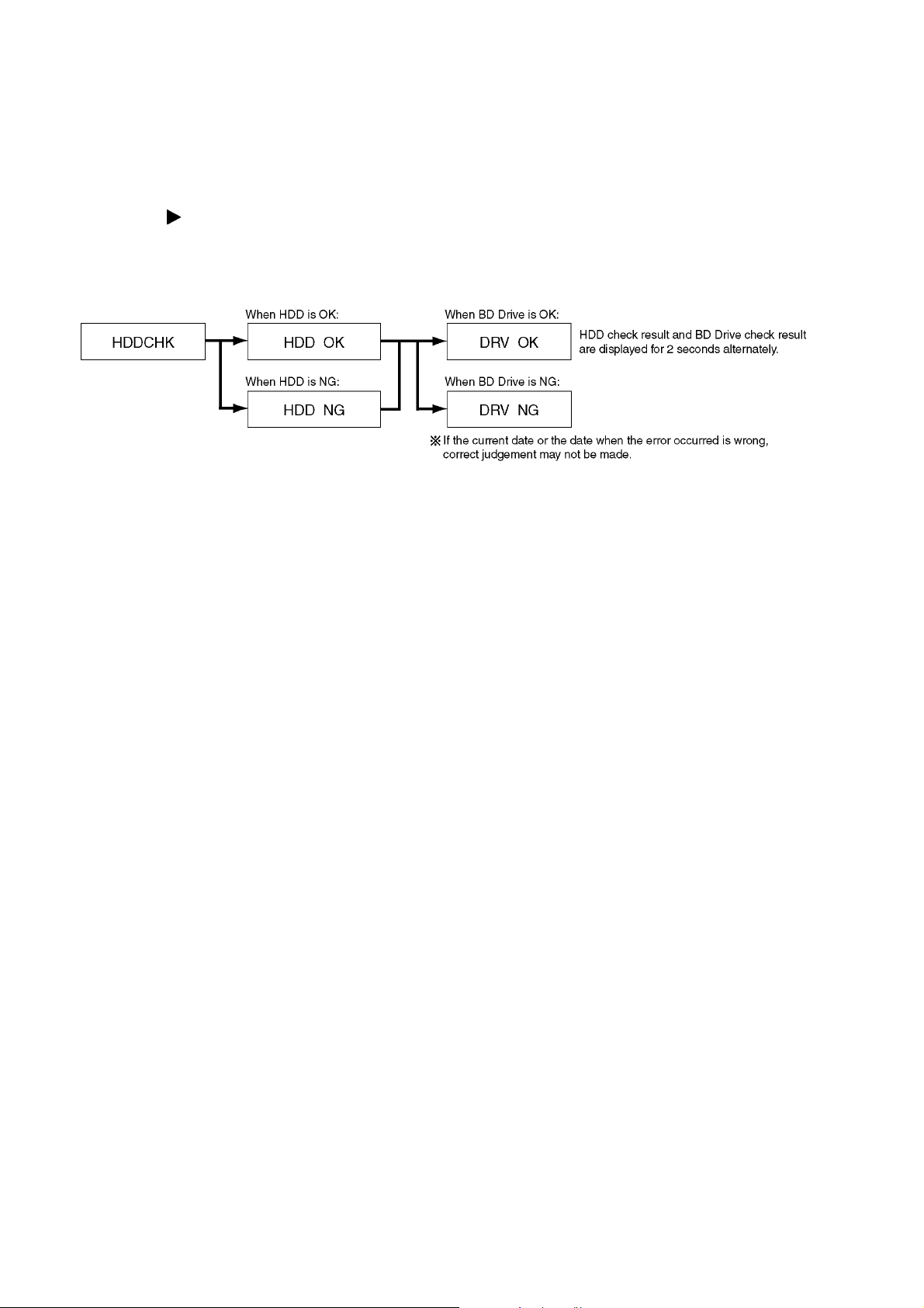
3.7.2. BD Drive Operation check flow
Perform quality judgement process of BD Drive according to the following operation.
*1: The drive supports the following error sense keys:
Contents Sense
key
NO SENSE 00 Successful completion.
RECOVERED ERROR 01 Successful completion through recovery.
NOT READY 02 The drive is unable to access the disc.
MEDIUM ERROR 03 An error caused by medium error has occurr ed.
HARDWARE ERROR 04 An error caused by the drive hardware has occurred.
ILLEGAL REQUEST 05 The CDB or parameter is illegal.
UNIT ATTENTION 06 The drive is alerting the host to some event.
DATA PROTECTED 07 The disc is read-protected or write-protected.
ABORTED COMMAND 0B The drive has aborted an I/O process or command execution due to a reason not relevant to any other
sense key, for example, a protocol violation on the interface.
Description
15

3.8. Operation check when a USB device is connected
You can check the operation status (normal or abn ormal) of the USB connection part of this unit easily as shown below.
Connect each device to the USB terminal on the front panel and check the operation status on the TV monitor.
Normal operation:
Automatically displayed when the USB connection is made to a digital camera, etc.
(Example below: When DivX materials have been recorded)
(*Displayed items differ depending on the recorded contents.)
Abnormal operation (Example 1):
Warning is displayed automatically if overcurrent is detected when a USB device is connected.
(*When a USB device or this unit's USB terminal shorts out or the power supply type of USB device is connected)
Abnormal operation (Example 2):
When the terminal of USB device is damaged or open, there is no display on the TV monitor.
16
3.9. Wi-Fi Module (Internal) Malfunction Check (Simplified Method)
3.9.1. Procedure of the Wi-Fi Module (Internal) Malfunction Check
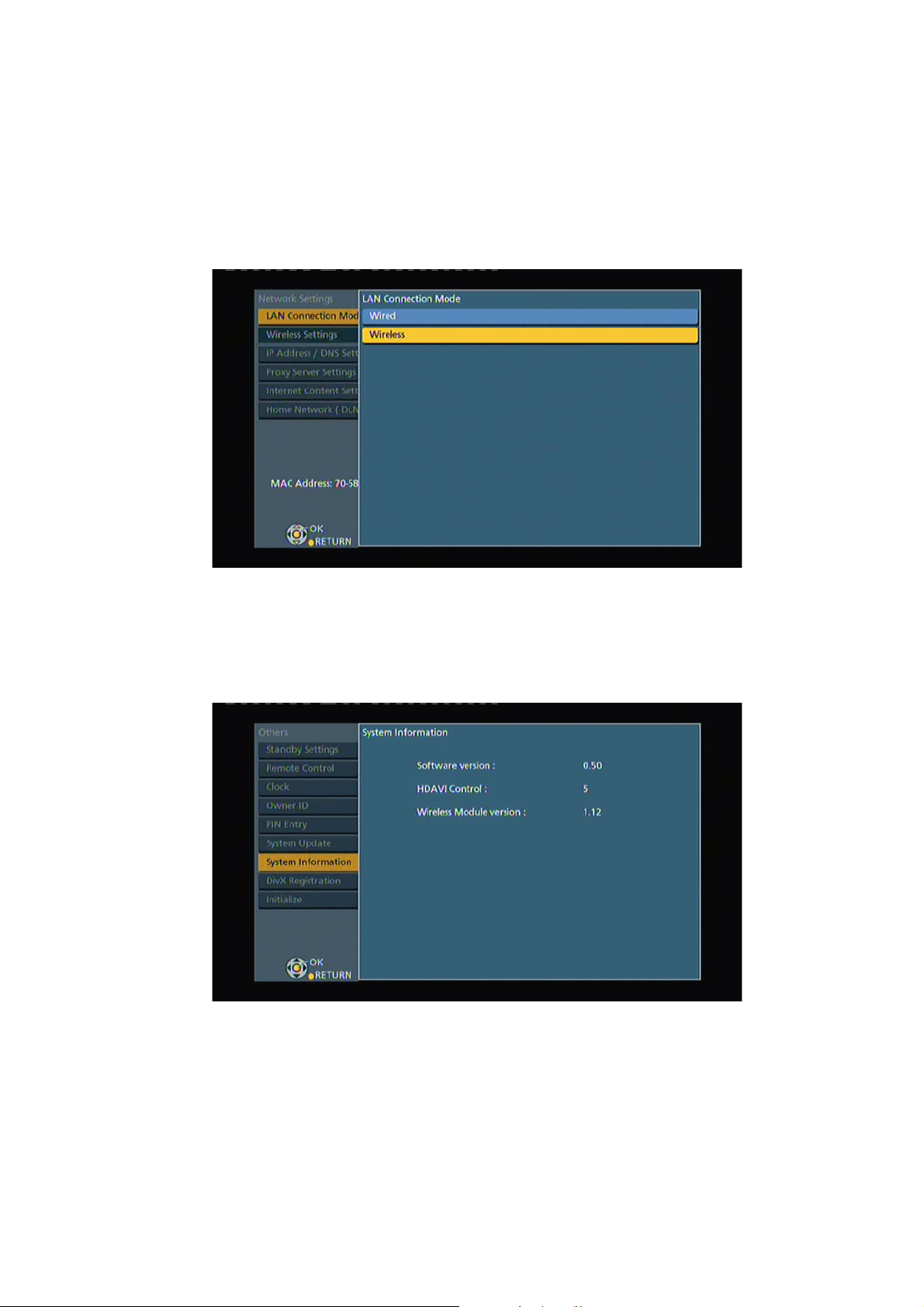
3.9.1.1. Method of Wireless LAN Setting
1. Press [FUNCTION MENU].
2. Select "Setup" in "Others", then press [OK].
3. Select "Network Setting" in "Network", then press [OK].
4. Select "Wireless" in "LAN Connection Mode".
5. Press [OK]. The following "Wireless Setting screen (example)" is displayed.
3.9.1.2. Method of displaying Wireless LAN Module Version
1. Press [FUNCTION MENU].
2. Select "Setup" in "Others", then press [OK].
3. Select "System Information" in "Others".
4. Press [OK]. The following "System Information screen (example)" is displayed.
17
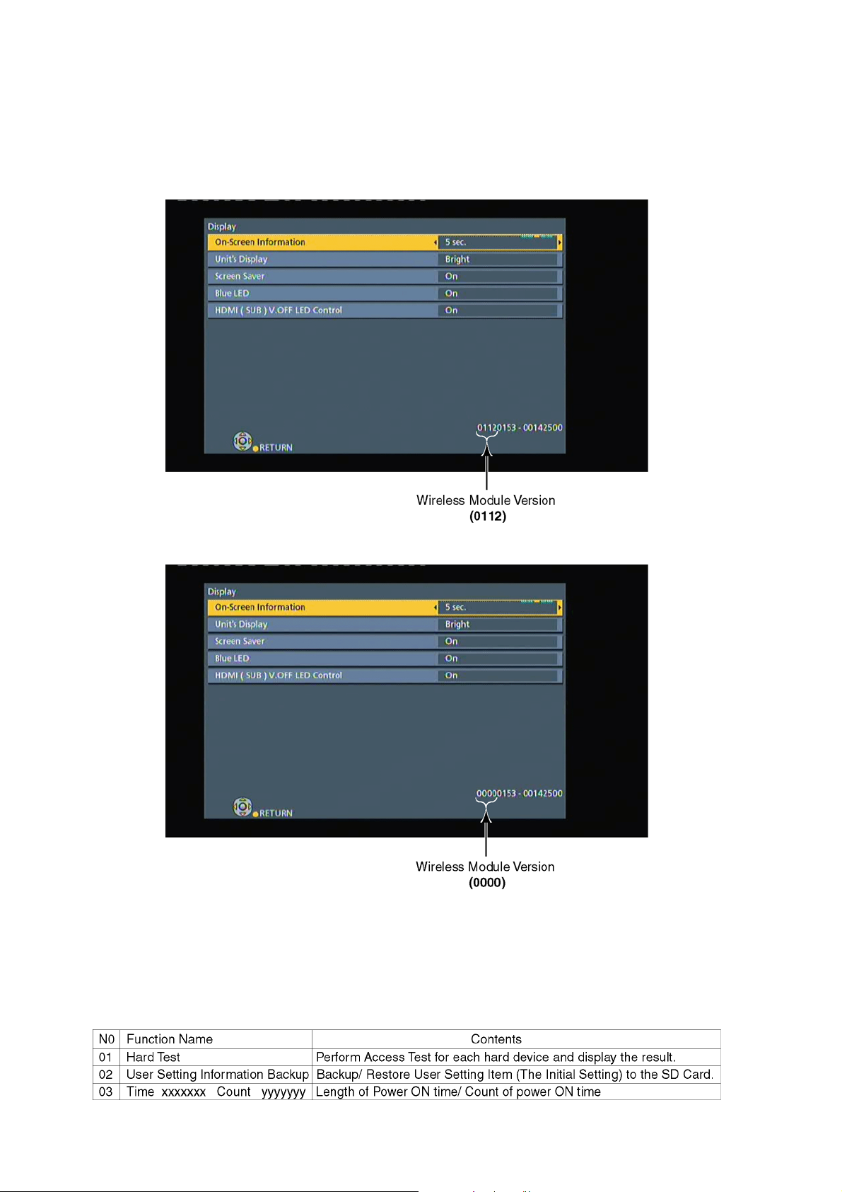
3.9.1.3. Confirm method of Wireless LAN Module invalidity/effective
1. Press [FUNCTION MENU].
2. Select "Setup" in "Others", then press [OK].
3. Select "Display" and press [OK].
4. Press [STATUS], over than 5seconds. The following "Display screen (example)" is displayed.
In case of Wireless LAN Module effective.
In case of Wireless LAN Module invalid.
5. In case of Wireless LAN Module effective, Wireless LAN Module or Wireless LAN Module connection cable may be the
source of problem.
6. Please finally check the operation of the fact.
3.10. Check with Tuner Service Mode
Inspect the inside components using the application for inspections by service personnel.
Main functions
18
1. Execute Tuner Service Mode
1) Turn the power on to receive digital broadcasting (HD broadcasting).
2) Press the [5] [9] and [RED] button simultaneously for five seconds, then [70 RET] is displayed on FL.
3) Press the [ ] button to select until [82 TSR] is displayed on FL.
4) Press the [OK] button.
5) It is shown to have entered the tuner service mode.
6) The command is transmitted by attached remote control.
2. Finishing Tuner Service Mode
Method 1: After turning the unit "OFF", pull out the AC cord.
Method 2: Repeat turning ON and OFF twice: P-OFF → P-ON → P-OFF → P-ON.
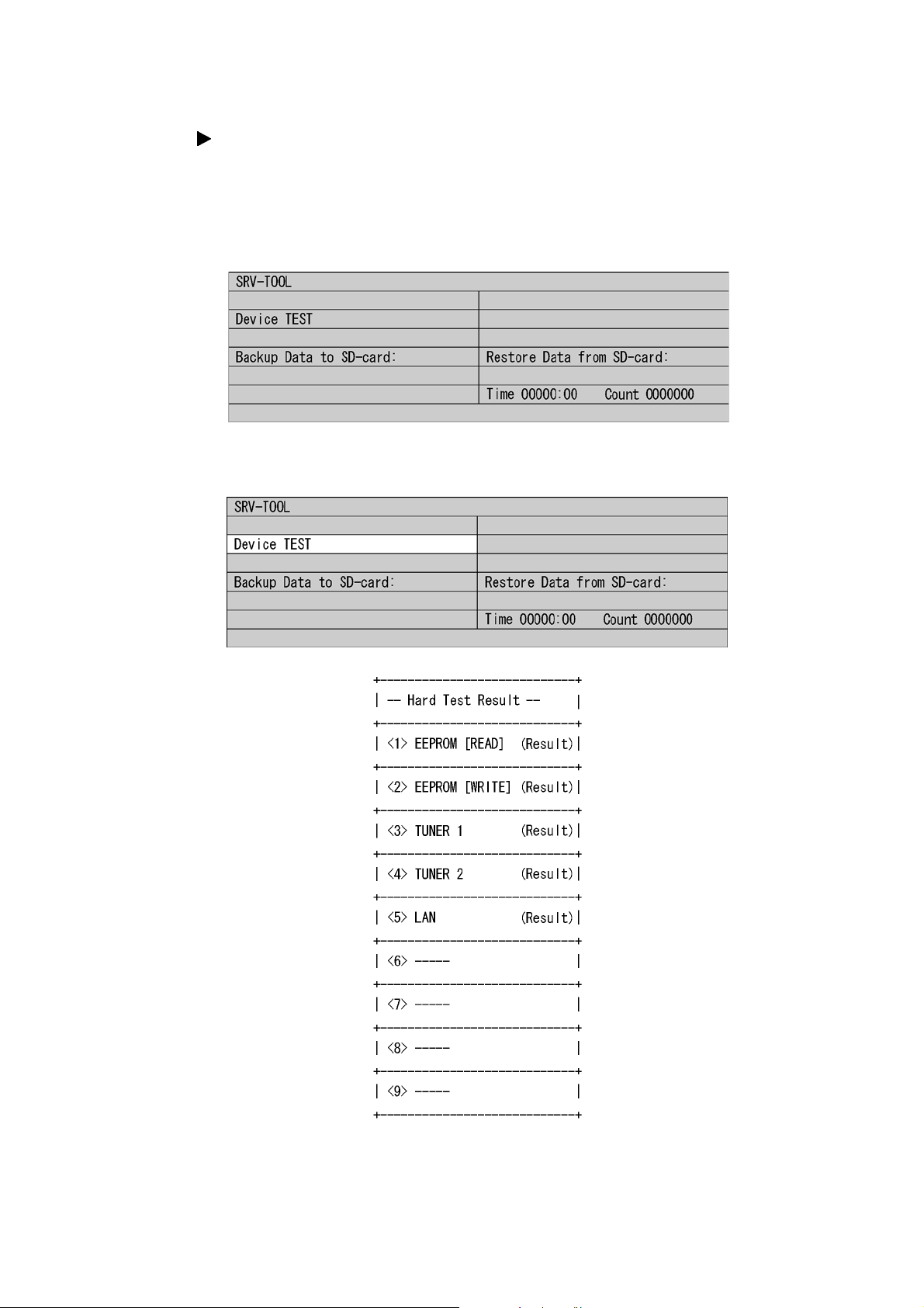
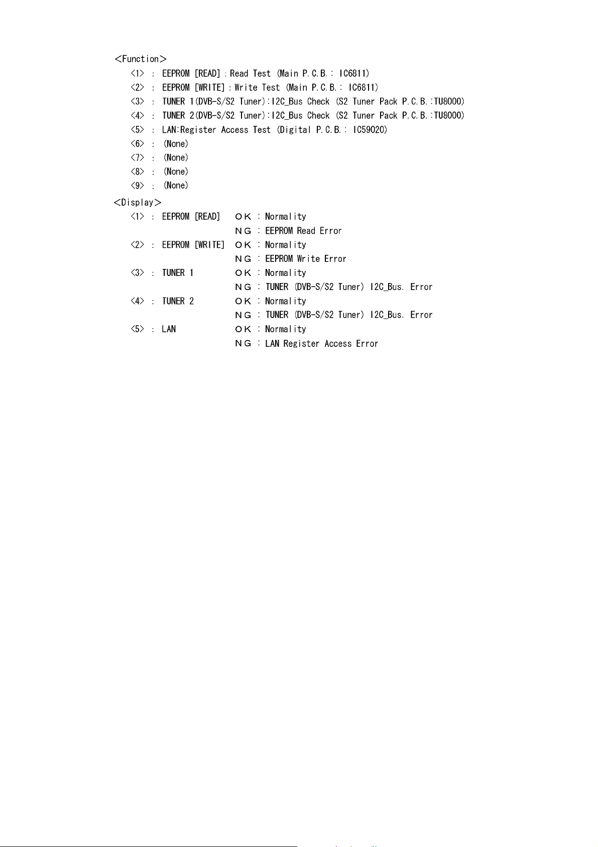
3.10.1. Hard Test (Device Test)
Perform Access Test for each hard device and display the result.
19
Note:
Hard test result does not guarantee that problems do not exist even if the result is OK.
The result is used as reference when any trouble occurs.
20

3.10.2. Use times and number of times of Power ON/OFF
Display accumulated time of Power ON and display number of times of Power ON/OFF.
*1 : Display accumulated time of Power ON
Display on a 15-minute basis
Example: 00123:15 → 123 hour 15 minute
*2 : Display number of times of Power ON/OFF
Example: 0000123 →123
3.10.3. User Setting Information Backup
Purpose
After the recorder is repaired, the restored setting information is not default, but the information before repaired.
Operation summary
Before starting repa ir, import data on memory of the unit to export the da ta to SD card on Tuner Service Mode display.
After the repair is finished, import the data on SD card to export the data to the me mory on th e unit by opera ting on Tuner Service
Mode display again.
• Data to be backed up
Each setting item that a user can set at "SET UP" (*1) and "DVB TUNING" (FUNCTION MENU → OTHERS → SET UP,
DVB TUNING, and "Program timer setting", "History information" etc.
* The following data cannot be backed up.
• Program chart data
• Dedicated areas for Internet site service providers (unique information for each company), broadcast mail, two-way
communication list, board, or favorite page
• Status saving systems (last channel except for UHF, drive selection status, etc.)
etc.
Note:
Of user setting information, only items selected and set on the initial Setup display can be backed up and restored.
*1: Of user setting information, except items selected and set on the initial Setup display.
21
Operation procedure
Preparation:
Prepare a SD card to export data stored in this unit.
Create the following directory on the SD card.
EEPBAKSD
Boot:
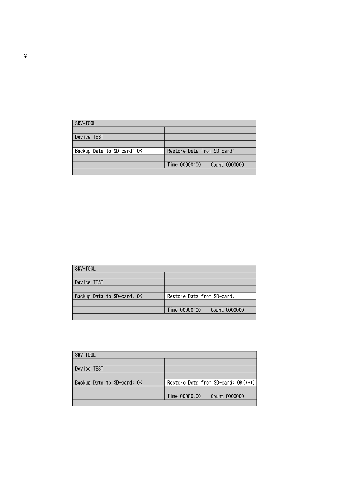
1. On Tuner Service Mode display
Using Remote Controller, move the cursor to user's setting information backup display position (Refer to below) on Tuner
Service Mode display.
2. Press [OK].
After "Try → OK" is displayed, the data is exported to SD card.
(Refer to below)
When OK(***) is displayed, the data is successfully exported.
Note:
If the backup file already exists in the SD card, the data is overwritten and "OK" is displayed.
3. Remove the SD card from the unit.
4. Turn the unit OFF to finish Tuner Service Mode.
Restoring the back up data to the unit
1. Turn the unit ON.
Perform the following: Function MENU - To Others - Setup - Others - Initialize - Shipping Condition.
2. Start Tuner Service Mode.
3. Insert the SD Card in save data to the unit.
4. Using Remote Controller, move the cursor to user's setting information backup display position (Refer to below) on Tuner Service Mode display.
5. Press [ENTER].
After "Try → OK" is displayed, the data is restored to SD card.
(Refer to below)
When OK(***) is displayed, the data is successfully exported.
6. Remove the SD card from the unit.
7. Turn the unit OFF to finish Tuner Service Mode.
22
4 Specifications
General
Power supply: AC 220 - 240V 50Hz
Power consumption: Approx. 64W (BST800), 60W (BST700/
BST701)
Power consumption
in standby mode:
Operating temperature:
Operating humidity
range:
Tuner system: DVB-S/S2
Antenna receive
frequency:
Input level: -65dBm to -25dBm
Input impedance Nominal 75 ohm
Demodulation QPSK, 8PSK
LNB input: F shape terminal female, power supply 13V/
LNB output: Not provided
RF Converter output:
DiSEqC Version 1.0 or Tone burst A/B, 22KHz 0.65vp-p
Video system: PAL/NTSC/SECAM(IN)
Recording system: MPEG2 (Hybrid VBR)/MPEG-4 AVC/H.264
Video in (PAL/
NTSC):
S-Video in (PAL/
NTSC):
RGB in (PAL): AV2 (21 pin) 0.7 Vp-p 75 ohm
Video out (PAL/
NTSC):
S-Video out (PAL/
NTSC):
RGB out (PAL): AV1 (21 pin) 0.7 Vp-p 75 ohm
Recording system: Dolby Digital (XP, SP, LP, EP mode: 2ch)
Audio in: AV1/AV2 (21 pin)
Input level: Standard: 0.5 Vrms, Full scale: 2.0 Vrms at 1
Input impedance: More than 10k ohm
Audio out: AV1/AV2 (21 pin), Audio Out L/R (pin jack)
Output level: Standard: 0.5 Vrms, Full scale: 2.0 Vrms at 1
Output impedance: Less than 1k ohm
Digital audio out: Optical terminal (PCM, Dolby Digital, DTS,
19 pin type A: 2 pcs (BST800)
19 pin type A: 1 pc (BST700/BST701)
• This unit supports "HDAVI Control 5" function.
500GB (BST800), 320GB (BST700/BST701)
Approx. 0.2W (Power save mode: ON)
Approx. 6.0W (Power save mode: OFF)
5°C - 40°C
10% - 80% RH (no condensation)
Television system
950MHz to 2150MHz
18V max. 400mA
Not provided
Video
AV1/AV2 (21 pin)
1 Vp-p 75 ohm
AV2 (21 pin)
1 Vp-p 75 ohm
AV1/AV2 (21 pin), Video out (pin jack)
1 Vp-p 75 ohm
AV1 (21 pin)
1 Vp-p 75 ohm
Audio
Dolby Digital (DR, HG, HX, HE, HL, HM mode:
Max 5.1 ch)
Dolby Digital Plus (DR mode: Max 5.1 ch)
MPEG 2ch (DR mode)
kHz
kHz
MPEG)
Coaxial terminal (PCM, Dolby Digital, DTS,
MPEG)
HDMI terminal (PCM, Dolby Digital, DTS,
MPEG, Dolby Digital Plus, Dolby TrueHD, DTS-
HD Master Audio, DTS-HD High Resolution
Audio)
HDMI Output
Internal HDD Capacity
Other terminals
USB Port: Type A: 2 pcs
SD Card Slot: 1 pc
Common Interface
slot:
LAN (Ethernet)
Port:
Approx.
Approx.
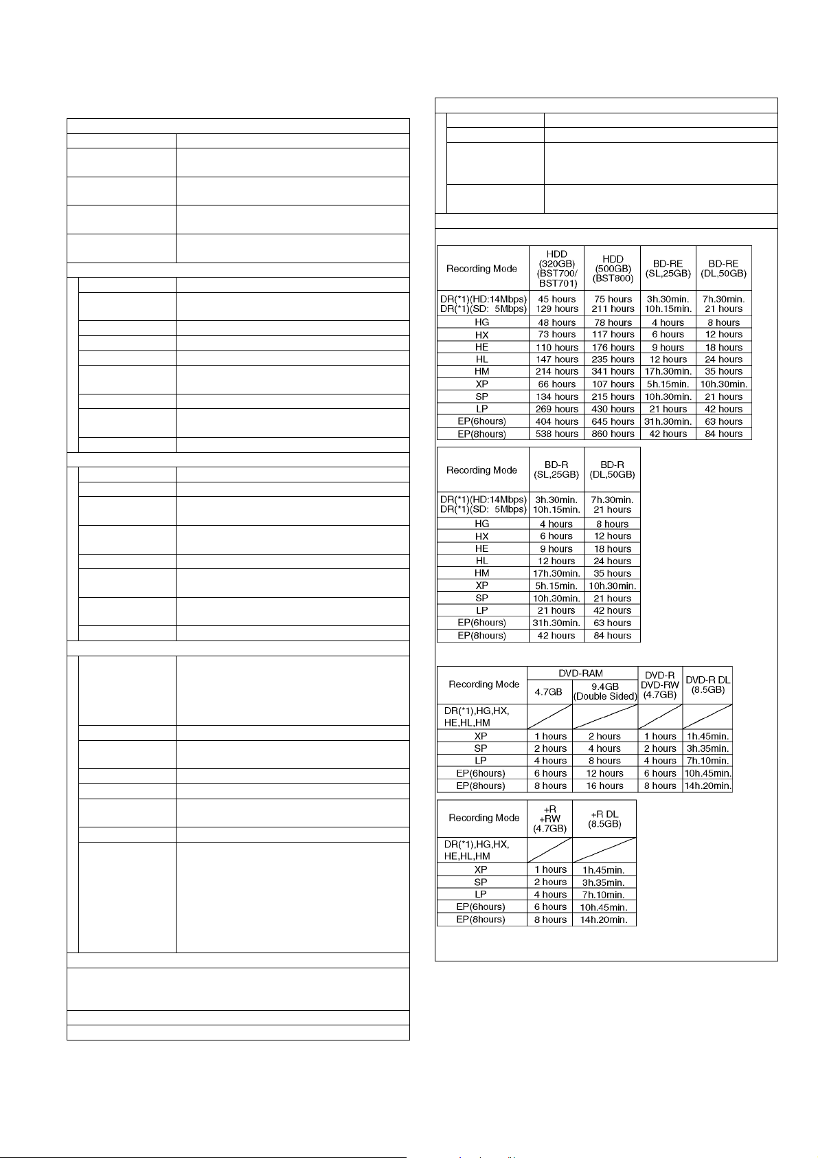
*1: Recording time of DR mode may vary depending on bit rate of
broadcasting.
2 pc
*Compliant with CENELEC EN 50221: February, 1997.
10BASE-T/100BASE-TX
Recording time
23
Maximum writing speed of discs
BD-RE (DL): Up to 2x speed
BD-RE (SL): Up to 2x speed
BD-R (DL): Up to 6x speed
BD-R (SL): Up to 6x speed
DVD-RAM: Up to 5x speed
DVD-R (SL): Up to 16x speed
DVD-R (DL): Up to 8x speed
DVD-RW: Up to 6x speed
+R (SL): Up to 16x speed
+R (DL): Up to 8x speed
+RW: Up to 4x speed
Maximum supporting speed of drive for each discs: Refer "Recordable
discs".
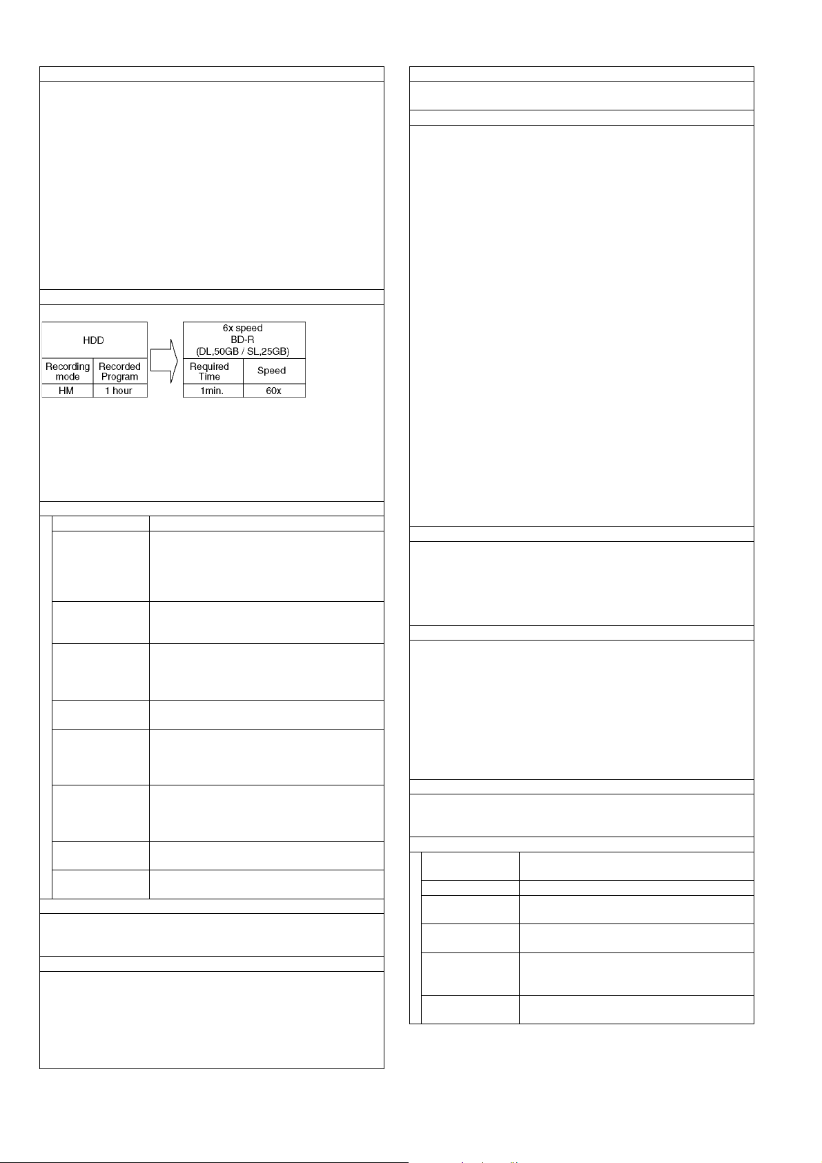
Copying speed HDD to BD-R in High Speed Copy
Approx.
Note)
The above rate in the list indicates the shortest time and fastest speed
required for copying one-hour title from HDD to the disc by HighSpeed copying.
The required amount of time and speed may vary depending on the
conditions such as the area where information is written or unique feature on the disc.
Recordable discs
BD-RE (SL/DL): 1-2X SPEED (Ver. 2.1)
BD-R (SL/DL): 1-2X SPEED (Ver. 1.1)
1-4X SPEED (Ver. 1.2)
1-6X SPEED (Ver. 1.3)
1-2X SPEED LTH type (Ver. 1.2)
1-6X SPEED LTH type (Ver. 1.3)
DVD-RAM: 2X SPEED (Ver. 2.0)
2-3X SPEED (Ver. 2.1)
2-5X SPEED (Ver. 2.2)
DVD-R (SL): 1X SPEED (Ver. 2.0)
1-4X SPEED (Ver. 2.0)
1-8X SPEED (Ver. 2.0)
1-16X SPEED (Ver. 2.1)
DVD-R (DL): 2-4X SPEED (Ver. 3.0)
2-8X SPEED (Ver. 3.0)
DVD-RW: 1X SPEED (Ver. 1.1)
1-2X SPEED (Ver. 1.1)
2-4X SPEED (Ver. 1.2)
2-6X SPEED (Ver. 1.2)
+R (SL): 2.4X SPEED (Ver. 1.0)
2.4-4X SPEED (Ver. 1.1)
2.4-8X SPEED (Ver. 1.2)
2.4-16X SPEED (Ver. 1.3)
+R (DL): 2.4X SPEED (Ver. 1.0)
2.4-8X SPEED (Ver. 1.1)
+RW: 2.4X SPEED (Ver. 1.1)
2.4-4X SPEED (Ver. 1.2)
Optical pick-up
System with 2 lens, 3 integration units
(405 nm wavelength for BDs, 661 nm wavelength for DVDs, 783 nm
wavelength for CDs)
LASER specification
Class 1 LASER Product (Pickup)
Wave length:
CD 783 nm wave length
DVD 661 nm wave length
BD 405 nm wave length
Laser power: No hazardous radiation is emitted with the safety protection
Regional Code
DVD: #2
BD: Region B
Playable discs
• BD-Video (Blu-ray 3D, BD-Live)
• BD-ROM Ver. 2.4
• BD-RE: Ver. 2.1, JPEG, MPO
• BD-RE DL: Ver. 2.1, JPEG, MPO
• BD-R: Ver. 1.3, LTH type Ver. 1.3, DivX (*5), MKV (*5)
• BD-R DL: Ver. 1.3, DivX (*5), MKV(*5)
• DVD-RAM: DVD-Video Recording format, AVCHD format, JPEG,
MPO
• DVD-R: DVD-Video format (*2), DVD-Video Recording format (*2),
AVCHD format (*2), JPEG (*3), MPO (*3), MP3 (*3), DivX (*3)(*4),
MKV (*3)(*4)
• DVD-R DL: DVD-Video format (*2), DVD-Video Recording format
(*2), AVCHD format (*2), JPEG (*3), MPO (*3), MP3 (*3), DivX
(*3)(*4), MKV (*3)(*4)
• DVD-RW: DVD-Video format (*2), DVD-Video Recording format
(*2), AVCHD format (*2)
• +R: Video (*2), AVCHD format (*2)
• +R DL: Video (*2), AVCHD format (*2)
• +RW: Video (*2), AVCHD format (*2)
• DVD-Video: DVD-Video format
• CD-Audio: CD-DA
• CD-R/CD-RW: CD-DA, JPEG (*3), MPO (*3), MP3 (*3), DivX (*3),
MKV (*3)
*2: Finalizing is necessary.
*3: ISO9660 level 1 or 2 (except for extended formats) and Joliet
This unit is compatible with multi-session.
This unit is not compatible with packet-writing.
*4: UDF 1.02 without ISO9660, UDF 1.5 with ISO9660
*5: UDF 2.5
Recording System
• BD-RE (SL/DL): Blu-ray Disc Rewritable format
• BD-R (SL/DL): Blu-ray Disc Recordable format
• DVD-RAM: DVD-Video Recording format
• DVD-R (SL/DL): DVD-Video format
• DVD-RW: DVD-Video format
• +R (SL/DL), +RW
SD Card
• SD Card Slot: SD Memory Card slot; 1 pc
• Compatible media: SD Memory Card (*6)
• Format: FAT12, FAT16, FAT32 (*7)
exFAT (In case of SDXC Memory Card)
• Data that can be played: JPEG, MPO, AVCHD format, MPEG-2
*6: Includes SDHC, SDXC Card
Includes miniSD™ Cards. (need a miniSD™ Adaptor.)
Includes microSD™/microSDHC/microSDXC Cards. (need a
microSD™ Adaptor.)
*7: Long file name is unsupported
USB device
• standard: USB 2.0 High Speed
• Format: FAT12, FAT16, FAT32
• Data that can be played: MP3, JPEG, MPO, DivX, MKV
MP3
Playable media: HDD, DVD-R, DVD-R DL, CD-R, CD-RW, USB
device
Compression rate: 32 kbps - 320 kbps
File format: • MP3 files must have the extension ".mp3" or
".MP3".
Sampling frequency:
Number of folders: Maximum number of folders recognizable
Number of files:
(tracks)
16 kHz, 22.05 kHz, 24 kHz, 32 kHz, 44.1 kHz,
48 kHz
(except for folders: HDD): 300 folders (including the root folder)
Maximum number of files recognizable (except
for HDD): 3000 files, HDD: 40000 files
24
JPEG/MPO
Playable media: HDD, BD-RE (SL/DL), DVD-RAM, DVD-R,
DVD-R DL, CD-R, CD-RW, SD Card, USB
device
File format: JPEG conforming DCF (Design rule for Cam-
era File system)
MPO conforming MPF (Multi Picture Format)
• JPEG files must have the extension ".jpg" or
".JPG".
• MPO files must have the extension ".mpo"
or ".MPO".
Compatible pixels: Between 34 x 34 and 8192 x 8192 pixels
Sub sampling is 4:2:2 or 4:2:0
This unit is not Compatible with MOTION JPEG
or PROGRESSIVE JPEG.
Number of folders: Maximum number of folders recognizable: 500
folders (including the root folder)
Number of files: BD-RE, DVD-RAM, DVD-R, CD-R, CD-RW , SD
Card, USB device:
Maximum number of files recognizable: 10000
files
HDD:
Maximum number of files recognizable: 20000
files
MOTION JPEG,
PROGRESSIVE
JPEG:
Playable media: BD-R (SL/DL), DVD-R, DVD-R DL, CD-R, CD-
File format: DivX files must have the extension ".DIVX" or
Number of folders: Maximum number of folders recognizable: 300
Number of files: Maximum number of files recognizable: 200
Support version:
Playable media: BD-R (SL/DL), DVD-R, DVD-R DL, CD-R, CD-
File format: • MKV files must have the extension ".MKV"
Number of folders: Maximum number of folders: 300 folders
Number of files: Maximum number of files: 200 files
Playable media: SD Card (*8), USB device (*9)
Codec: MPEG2
File format: SD-Video format (*10) used on Standard Defi-
*8: Video Recording conversion and transfer is possible from SD
card to HDD or DVD-RAM disc.
After Video Recording conversion and transfer to HDD or DVDRAM disc is completed, the playback becomes possible.
*9: Video Recording conversion and transfer is possible from USB
device to HDD or DVD-RAM disc.
After Video Recording conversion and transfer to HDD or DVDRAM disc is completed, the playback becomes possible.
*10: SD-Video Entertainment Video Profile.
Not supported
DivX
RW, USB device
".divx", ".AVI" or ".avi".
folders (including the root folder)
files
Official DivX
DivX Certified to play DivX video up to HD
1080p, including premium content.
GMC (Global Motion Compensation) is not sup-
ported.
DivX, DivX Certified, and associated logos are
trademarks of DivX, Inc. and are used under
license.
RW, USB device
MPEG-4 AVC (H.264) profile is up to HIGH
Profile, Level 4.
AAC-LC, MP3, Dolby Digital audio, DTS and
PCM can be decoded.
or ".mkv".
(including the root folder)
SD (Standard Definition)-Video
nition Camera (Panasonic and some other's)
®
Certified product.
MKV
HD (High Definition)-Video
Playable media: SD Card, USB device (*11)
Codec: MPEG-4 AVC/H.264
File format: AVCHD format conforming
*11: V ideo Recording conversion and transfer is possible from USB
device to HDD, BD-RE (SL/DL) or BD-R (SL/DL) disc.
After Video Recording conversion and transfer to HDD, BD-RE (SL/
DL) or BD-R (SL/DL) disc is completed, the playback becomes possible.
WLAN (BST800)
Antenna: Tx1, Rx2
Standard compliance:
Transmission system:
Frequency Range: IEEE802.11n / IEEE802.11a
Transfer rate (standard)(*12):
Access mode: Infrastructure mode
Security (*13): WPA2-PSK (TKIP/AES) / WPA-PSK (TKIP/
*12: Transfer rates are theoretical values; however, actual communication rate will vary according to communication environment or
connected equipment.
*13: This unit supports WPA and WPA2 encryption.
430 mm (W) × 66 mm (H) × 238 mm (D) (BST800)
(excluding the projecting parts)
430 mm (W) × 66 mm (H) × 249 mm (D) (BST800)
(including the projecting parts)
430 mm (W) × 59 mm (H) × 238 mm (D) (BST700/BST701)
(excluding the projecting parts)
430 mm (W) × 59 mm (H) × 249 mm (D) (BST700/BST701)
(including the projecting parts)
Approx. 3.3 kg (BST800)
Approx. 3.2 kg (BST700/BST701)
These models use lead free solder (PbF)
IEEE802.11n / IEEE802.11a / IEEE802.11g /
IEEE802.11b
MISO-OFDM system / OFDM system / DSSS
system
5.15 GHz-5.35 GHz, 5.47 GHz-5.725 GHz
EEE802.11g / IEEE802.11b/ /IEEE802.11n
2.4 GHz-2.4835 GHz
IEEE802.11n Tx Max 150 Mbps / Rx Max
300Mbps
IEEE802.11g / IEEE802.11a Max 54 Mbps
IEEE802.11b Max 11 Mbps
AES) / WEP (64 bit/128bit)
Dimensions
Mass
Solder
Note:
Specifications are subject to change without notice.
25

5 Location of Controls and Components
26
27
6 Installation Instructions
6.1. Taking out the Disc from BD-Drive Unit when the Disc cannot be ejected
by OPEN/CLOSE button
6.1.1. Forcible Disc Eject
6.1.1.1. When the power can be turned off.
1. Turn off the power, press and hold [OK], [BL UE] and [YELLOW] on the remote co ntrol at the same time for mo re than 5 seconds.-"00 RET" is displayed on the unit's display.
2. Repeatedly press [ ] on the remote control or [POWER] on the unit until "06 FTO" is displayed on the unit's display.
3. Press [OK] on the remote control or [OPEN/CLOSE] on the unit.
6.1.1.2. When the power can not be turned off.
1. Press [POWER] key on the front panel for over 4 seconds to turn off the power forcibly, press and hold [OK], [BLUE] and
[YELLOW] on the remote control at the same time for more than 5 seconds.
-"00 RET" is displayed on the unit's display.
2. Repeatedly press [ ] on the remote control or [POWER] on the unit until "06 FTO" is displayed on the unit's display.
3. Press [OK] on the remote control or [OPEN/CLOSE] on the unit.
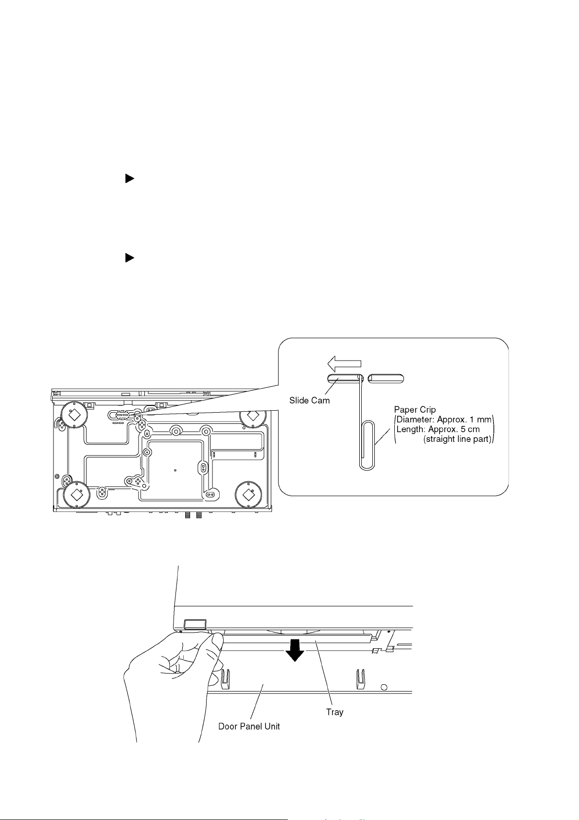
6.1.2. When the Forcible Disc Eject can not be done.
1. Turn off the power and pull out AC cord.
2. Put deck so that bottom can be seen.
3. Slide SLIDE CAM by Paper Clip or minus screw driver (small) in the direction of arrow to eject tray slightly.
4. Put deck upward, and pick out Tray by finger.
28
7 Service Mode
7.1. Self-Diagnosis and Special Mode Setting
7.1.1. Self-Diagnosis Functions
Self-Diagnosis Function provides information for errors to service personnel by "Self-Diagnosis Display" when any error has
occurred.
U**, H** and F** are stored in memory and held.
You can check latest error code by transmitting [0] [1] of Remote Controller in Service Mode.
Automatic Display on FL will be cancelled when the power is turned off or AC input is turned off during self-diagnosis display is ON.
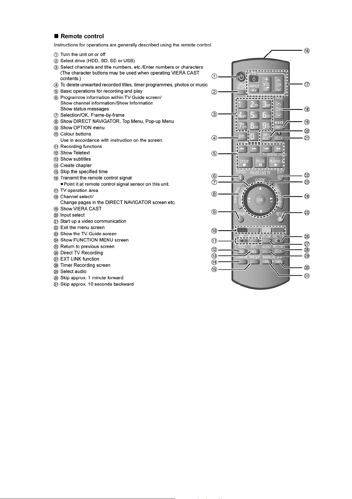
Remote Control:
[R] = [RED]
[Y] = [YELLOW]
[B] = [BLUE]
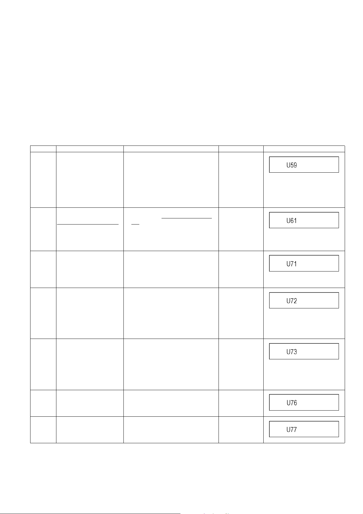
Error Code Diagnosis contents Description Monitor Display Automatic FL display
U59 Abnormal inner temperature
detected
U61 The unit is carrying out its
recovery process.
(with no disc in the disc tray)
U71 HDMI incompatible error
(HDCP incompatible)
U72 HDMI connection error
(communication error)
U73 HDMI connection error
(authentication error)
U76 HDMI connection error HDMI cannot be output because you are
Display appears when internal temperature
of deck reaches limit temperature.
The power is turned off forcibly.
For 30 minutes after this, all key entries are
disabled. (Fan motor operates at the highest speed for the first 5 minutes. For the
remaining 25 minutes, fan motor is also
stopped.) The event is saved in memory as
well.
• The unit detected an error while recording or playing with no disc in the disc
tray. The unit is carrying out its recovery
process. This process restores the unit
to normal operation. The unit is not broken.
Wait until the message disappears.
Display this error when the equipment
(compatible with DVI such as TV, amplifier
etc.) connected to the unit by HDMI is
incompatible with HDCP.
*HDCP=High-bandwidth Digital Content
Protection
This error is displayed when there are any
communication problems with the unit and
the equipments (TV, amplifier etc.) connected to the unit by HDMI. (or when there
is a problem with the HDMI cable)
When authentication error occurs while the
equipments (TV, amplifier etc.) are connected by HDMI. (or when there is a problem with the HDMI cable)
connected to a model that does not support
copyright protection.
No display
U59 is displayed for 30 minutes.
No display
No display
No display
U72 display disappears when error
has been solved by Power OFF/ON
of connecting equipment or by
inserting/removing of HDMI cable.
No display
U73 display disappears when error
has been solved by Power OFF/ON
of connecting equipment or by
inserting/removing of HDMI cable.
No display
U77 Illegal disc error Due to the current disc not having autho-
rized copyright information, video output is
not performed.
29
No display
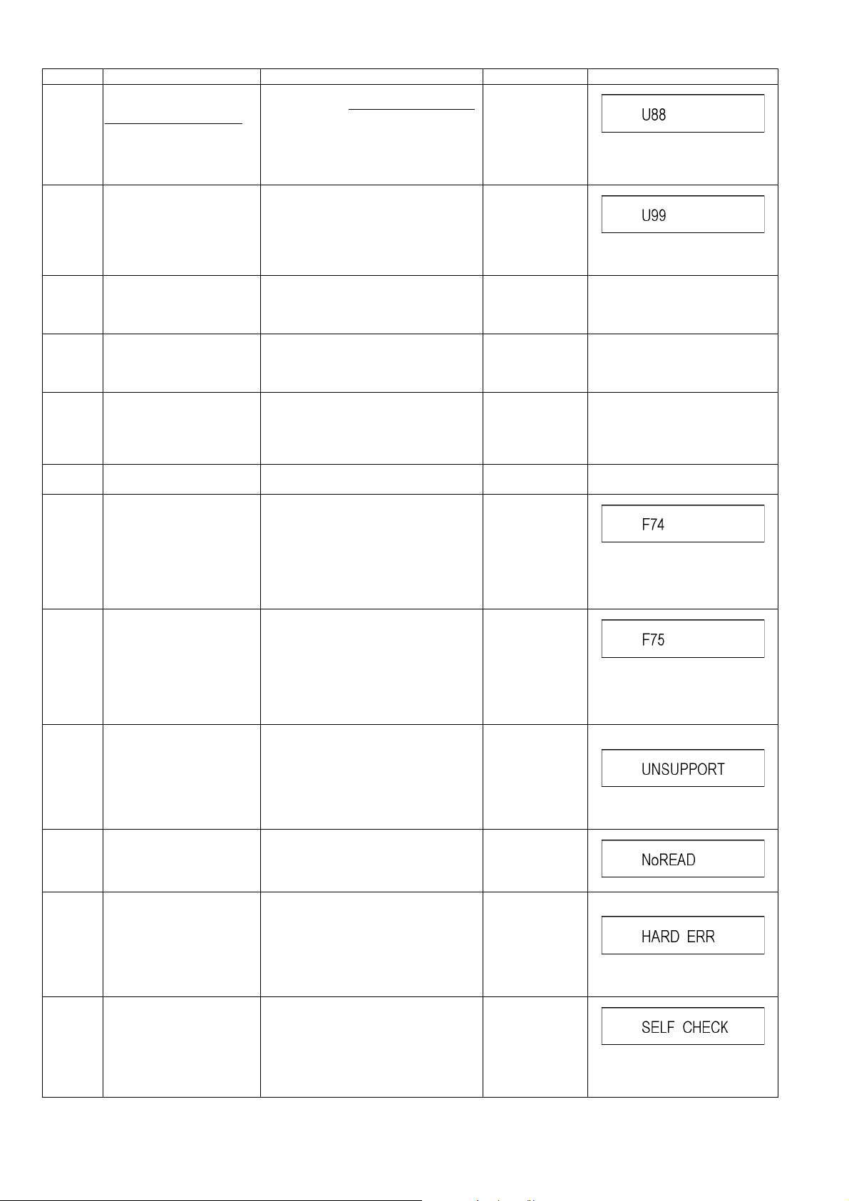
Error Code Diagnosis contents Description M onitor Display Automatic FL display
U88 The unit is carrying out its
recovery process.
(with a disc in the disc tray)
U99 Hang-up Displayed when communication error has
H19 02 Inoperative fan motor When inoperative fan motor is detected
F00 No error information Initial setting for error code in memory
F34 Initialization error when main
microprocessor is started up
for program recording
F58 Drive hardware error When drive unit error is detected, the event
F74 HDMI Device Key Communi-
cation error.
F75 HDMI Device Key Information
UNSUPPORT
NO READ Disc read error *A disc is flawed or dirty.
error
Unsupported disc error *An unsupported format disc was played,
• The unit detected an error while recording or playing with a disc in the disc tray
The unit is carrying out its recovery process. This process restores the unit to
normal operation. The unit is not broken.
Wait until the message disappears.
occurred between Main microprocessor
and Timer microprocessor.
after powered on, the power is turned off
automatically.
The event is saved in memory.
(Error code Initialization is possible with
error code initialization and main unit initialization.)
When initialization error is detected after
starting up main microprocessor for program recording, the power is turned off
automatically.
The event is saved in memory.
is saved in memory.
HDMI connection could not be authenticated due to a transfer malfunction.
Factor of HDMI Device key-road failure
• When HDMI LSI is damaged.
• When the bus line of I2C doesn't operate normally.
• When device key information recorded
is damaged.
HDMI connection could not be authenticated due to an internal data malfunction.
Factor of HDMI Device key-road failure
• When HDMI LSI is damaged.
• When the bus line of I2C doesn't operate normally.
• When device key information recorded
is damaged.
although the drive starts normally.
*The data format is not supported, although
the media type is supported.
*Exceptionally in case of the disc is dirty.
*A poor quality failed to start.
*The track information could not be read.
No display
.
No display
Displayed is left until the [POWER]
key is pressed.
No display No display
No display No display
No display No display
No display No display
No display
No display
"This disc is
incompatible."
"Cannot read.
Please check the
disc."
Display for 5 seconds.
The character indication flows sideways.
HARD
ERR
SELF
CHECK
Drive error The drive detected a hard error. "BD drive error." Display for 5 seconds.
The character indication flows sideways.
Restoration operation Since the power cord fell out during a
power failure or operation, it is under restoration operation.
*It will OK, if a display disappears automatically. If a display does not disappear, there
is the possibility that defective Digital P.C.B.
/ BD drive.
No display
The character indication flows sideways.
30
 Loading...