

Panasonic DMP-BDT165EB, DMP-BDT165EF, DMP-BDT165EG, DMP-BDT166EB, DMP-BDT166EG Service Manual
Page 1
ORDER NO.CHM1501004CE
Blu-ray Disc Player
Model No. DMP-BDT165EB
DMP-BDT165EF
DMP-BDT165EG
DMP-BDT166EB
DMP-BDT166EG
Colour
(K).......................Black Type (DMP-BDT165EG/EB/EF)
(S).......................Silver Type (DMP-BDT166EG/EB)
Panasonic Corporation © 2015.
Unauthorized copying and distribution is a violation
of law.
Page 2
234
Page 3
Page 4

TABLE OF CONTENTS
PAG E PAG E
1 Safety Precautions -----------------------------------------------5
1.1. General guidelines -----------------------------------------5
2Warning--------------------------------------------------------------6
2.1. Prevention of Electrostatic Discharge (ESD)
to Electrostatic Sensitive (ES) Devices---------------6
2.2. Precaution of Laser Diode -------------------------------7
2.3. Service caution based on legal restrictions----------8
2.4. Static Electricity Protection Measures ----------------9
2.5. Ground for electrostatic breakdown
prevention----------------------------------------------------9
3 Service Navigation---------------------------------------------- 10
3.1. Combination of Multiple Pressing on the
Remote Control------------------------------------------- 10
3.2. The display position of TV ----------------------------- 10
3.3. Entering Special Modes with Combination of
Multiple Pressing on the Remote Control ---------- 10
3.4. How to Update Firmware------------------------------- 12
4 Specifications ---------------------------------------------------- 15
5 Location of Controls and Components------------------ 16
6 Operating Instructions ---------------------------------------- 17
6.1. Taking out the Disc from BD-Drive Unit when
the Disc cannot be ejected by OPEN/CLOSE
button-------------------------------------------------------- 17
7 Service Mode ----------------------------------------------------- 18
7.1. Special Mode Setting and Service mode----------- 18
8 Service Fixture & Tools --------------------------------------- 30
9 Disassembly and Assembly Instructions --------------- 31
9.1. Unit----------------------------------------------------------- 31
9.2. Drive Unit--------------------------------------------------- 34
9.3. Disassembly from the traverse unit, assembly
of the optical pick-up unit, and precautions on
ESD-preventive------------------------------------------- 39
9.4. Adjustment of BD Drive--------------------------------- 44
10 Measurements and Adjustments -------------------------- 47
10.1. Service Positions -----------------------------------------47
10.2. Caution for Replacing Parts ---------------------------48
11 Block Diagra m --------------------------------------------------- 49
11.1. Overall Block Diagram ----------------------------------49
11.2. Digital P.C.B. Regulator Block Diagram ------------ 50
11.3. Digital (Back End Section) Block Diagram --------- 51
11.4. Digital (Front End Section) Block Diagram -------- 52
12 Wiring Connection Diagram --------------------------------- 53
12.1. Interconnection Schematic Diagram ---------------- 53
Page 5
1 Safety Precautions
1.1. General guidelines
1. When servicing, observe the original lead dress. If a short circuit is found, replace all parts which have been overheated or
damaged by the short circuit.
2. After servicing, see to it that all the protective devices such as insulation barriers, insulation papers shields are properly
installed.
3. After servicing, make the following leakage current checks to prevent the customer from being exposed to shock hazards.
1.1.1. Leakage current cold check
1. Unplug the AC cord and connect a jumper between the
two prongs on the plug.
2. Measure the resistance value, with an ohmmeter,
between the jumpered AC plug and each exposed metallic cabinet part on the equipment such as screwheads,
connectors, control shafts, etc. When the exposed metallic part has a return path to the chassis, the reading
should be between 1MΩ and 5.2MΩ.
When the exposed metal does not have a return path to
the chassis, the reading must be .
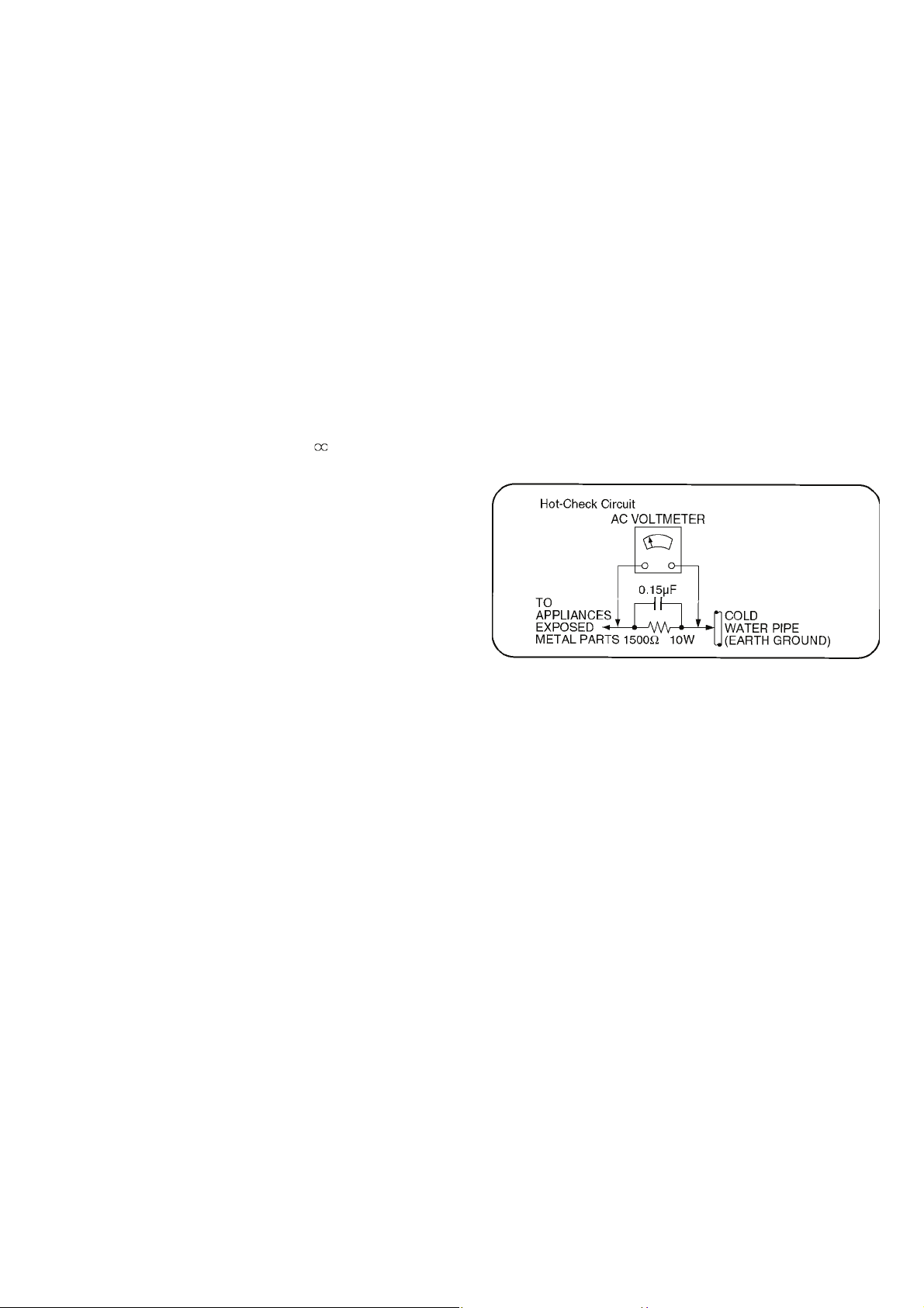
1.1.2. Leakage current hot check (See Figure 1.)
1. Plug the AC cord directly into the AC outlet. Do not use
an isolation transformer for this check.
2. Connect a 1.5kΩ, 10 watts resistor, in parallel with a
0.15μF capacitors, between each exposed metallic part
on the set and a good earth ground such as a water pipe,
as shown in Figure 1.
3. Use an AC voltmeter, with 1000 ohms/volt or more
sensitivity, to measure the potential across the resistor.
4. Check each exposed metallic part, and measure the
voltage at each point.
5. Reverse the AC plug in the AC outlet and repeat each of
the above measurements.
6. The potential at any point should not exceed 0.75 volts
RMS. A leakage current tester (Simpson Model 229 or
equivalent) may be used to make the hot checks, leakage
current must not exceed 1/2 milliampere. In case a measurement is outside of the limits specified, there is a possibility of a shock hazard, and the equipment should be
repaired and rechecked before it is returned to the customer.
5
Page 6
2Warning
2.1. Prevention of Electrostatic Discharge (ESD) to Electrostatic Sensitive (ES) Devices
Some semiconductor (solid state) devices can be damaged easily by static electricity. Such components commonly are called Electrostatic Sensitive (ES) Devices. Examples of typical ES devices are integrated circuits and some field-effect transistors and semiconductor "chip" components. The following techniques should be used to help reduce the incidence of component damage
caused by electrostatic discharge (ESD).
1. Immediately before handling any semiconductor component or semiconductor-equipped assembly, drain off any ESD on your
body by touching a known earth ground. Alternatively, obtain and wear a commercially available discharging ESD wrist strap,
which should be removed for potential shock reasons prior to applying power to the unit under test.
2. After removing an electrical assembly equipped with ES devices, place the assembly on a conductive surface such as aluminum foil, to prevent electrostatic charge buildup or exposure of the assembly.
3. Use only a grounded-tip soldering iron to solder or unsolder ES devices.
4. Use only an anti-static solder removal device. Some solder removal devices not classified as "anti-static (ESD protected)" can
generate electrical charge sufficient to damage ES devices.
5. Do not use freon-propelled chemicals. These can generate electrical charges sufficient to damage ES devices.
6. Do not remove a replacement ES device from its protective package until immediately before you are ready to install it. (Most
replacement ES devices are packaged with leads electrically shorted together by conductive foam, aluminum foil or comparable conductive material).
7. Immediately before removing the protective material from the leads of a replacement ES device, touch the protective material
to the chassis or circuit assembly into which the device will be installed.
Caution
Be sure no power is applied to the chassis or circuit, and observe all other safety precautions.
8. Minimize bodily motions when handling unpackaged replacement ES devices. (Otherwise harmless motion such as the
brushing together of your clothes fabric or the lifting of your foot from a carpeted floor can generate static electricity sufficient
to damage an ES device).
6
Page 7
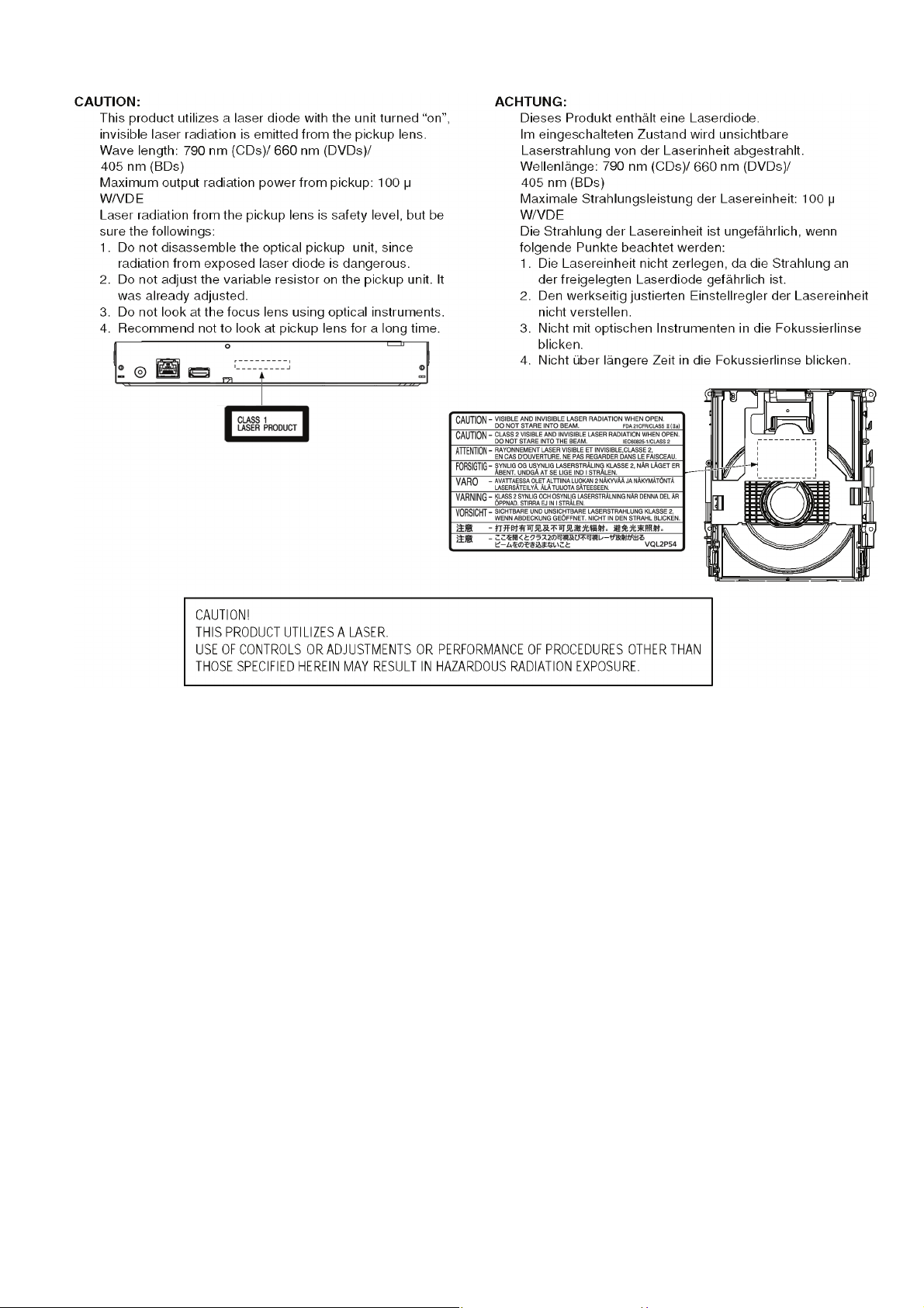
2.2. Precaution of Laser Diode
7
Page 8

2.3. Service caution based on legal restrictions
2.3.1. General description about Lead Free Solder (PbF)
The lead free solder has been used in the mounting process of all electrical components on the printed circuit boards used for this
equipment in considering the globally environmental conservation.
The normal solder is the alloy of tin (Sn) and lead (Pb). On the other hand, the lead free solder is the alloy mainly consists of tin
(Sn), silver (Ag) and Copper (Cu), and the melting point of the lead free solder is higher approx.30 degrees C (86°F) more than that
of the normal solder.
Definition of PCB Lead Free Solder being used
The letter of “PbF” is printed either foil side or components side on the PCB using the lead free solder.
(See right figure)
Service caution for repair work using Lead Free Solder (PbF)
• The lead free solder has to be used when repairing the equipment for which the lead free solder is used.
(Definition: The letter of “PbF” is printed on the PCB using the lead free solder.)
• To put lead free solder, it should be well molten and mixed with the original lead free solder.
• Remove the remaining lead free solder on the PCB cleanly for soldering of the new IC.
• Since the melting point of the lead free solder is higher than that of the normal lead solder, it takes the longer time to melt the
lead free solder.
• Use the soldering iron (more than 70W) equipped with the temperature control after setting the temperature at 350±30 degrees
C (662±86°F).
Recommended Lead Free Solder (Service Parts Route.)
• The following 3 types of lead free solder are available through the service parts route.
SVKZ000001-----------(0.3mm 100g Reel)
SVKZ000002-----------(0.6mm 100g Reel)
SVKZ000003-----------(1.0mm 100g Reel)
Note
* Ingredient: Tin (Sn) 96.5%, Silver (Ag) 3.0%, Copper (Cu) 0.5%. (Flux cored)
8
Page 9
2.4. Static Electricity Protection Measures
• The laser diode in the traverse unit (optical pick-up) may break down due to potential difference caused by static electricity of
clothes or human body.
So, be careful of electrostatic breakdown during repair of the traverse unit (optical pick-up).
2.5. Ground for electrostatic breakdown prevention
• As for parts that use optical pick-up (laser diode), the optical pick-up is destroyed by the static electricity of the working environment.
Repair in the working environment that is grounded.
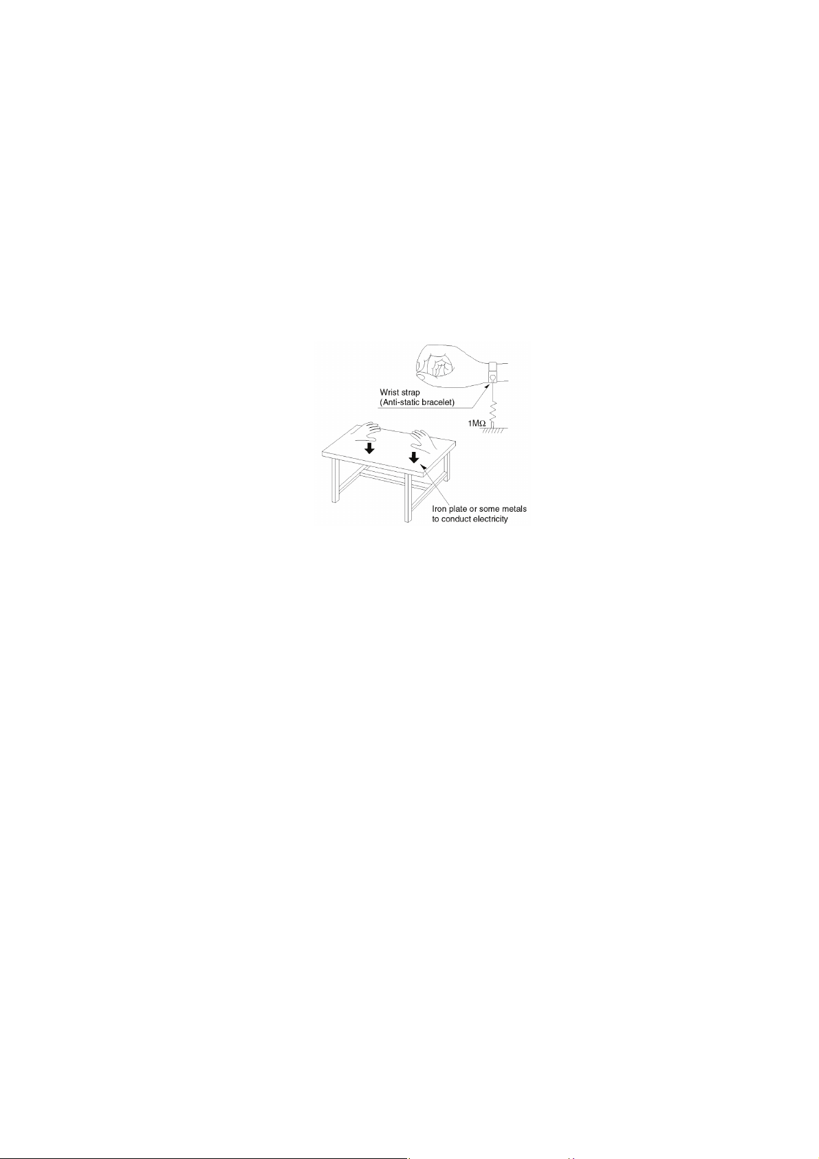
2.5.1. Work table grounding
• Put a conductive material (sheet) or steel sheet on the area where the traverse unit (optical pick-up) is placed, and ground the
sheet.
2.5.2. Human body grounding
• Use the anti-static wrist strap to discharge the static electricity from your body.
2.5.3. When exchange the BDP Drive
• Before remove the ESD prevention bag, make sure to use the anti-static wrist strap to discharge the static electricity when
replace the BDP Drive.
Note:
The ESD prevention bag is used to replace the original short-circuit point.
It can be removed while placing the BDP Drive.
9
Page 10
3 Service Navigation
3.1. Combination of Multiple Pressing on the Remote Control
Press multi-buttons (in combination) on the remote control simultaneously for operations, such as initialization or service mode, etc.
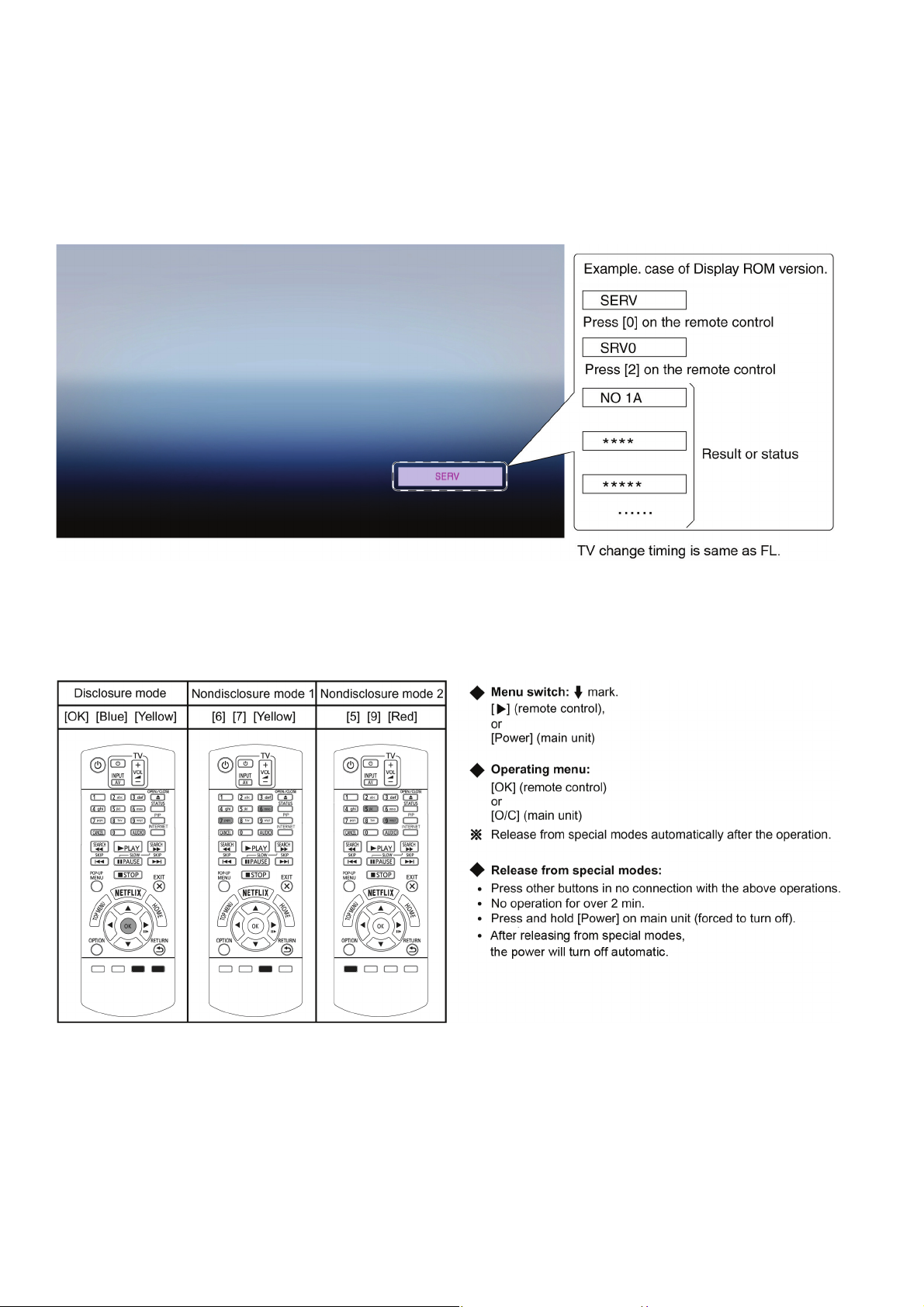
3.2. The display position of TV
Special modes display of this unit changes to TV display from the original FL display.
3.3. Entering Special Modes with Combination of Multiple Pressing on the Remote Control
Enter the following special modes by multiple pressing functions on the supplied remote control.
After entering each mode, switch to the desired menus for operation.
10
Page 11
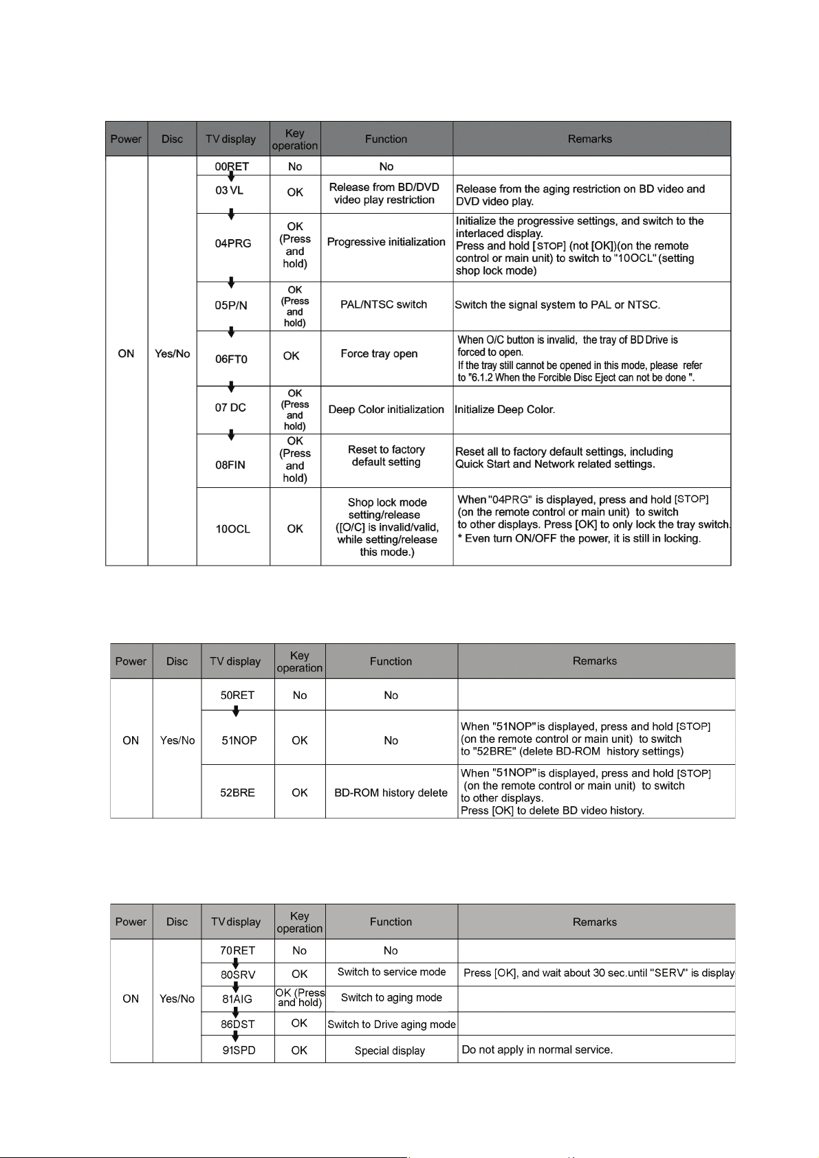
3.3.1. Disclosure mode (Combination of multiple pressing: [OK] [Blue] [Yellow])
Press and hold [OK] [Blue] [Yellow] on the remote control simultaneously for 5 sec., then "00RET" is displayed on TV display
window.
3.3.2. Nondisclosure mode 1 (Combination of multiple pressing: [6] [7] [Yellow])
Press and hold [6] [7] [Yellow] on the remote control simultaneously for about 5 sec., then "50RET" is displayed on TV display
window.
3.3.3. Nondisclosure mode 2 (Combination of multiple pressing: [5] [9] [Red])
Press and hold [5] [9] [Red] on the remote control simultaneously for about 5 sec., then "70RET" is displayed on TV display
window.
11
Page 12
3.4. How to Update Firmware
The firmware of the unit may be renewed to improve the quality including operational performance and playability.
Make sure to refer the following procedure when performing version-up.
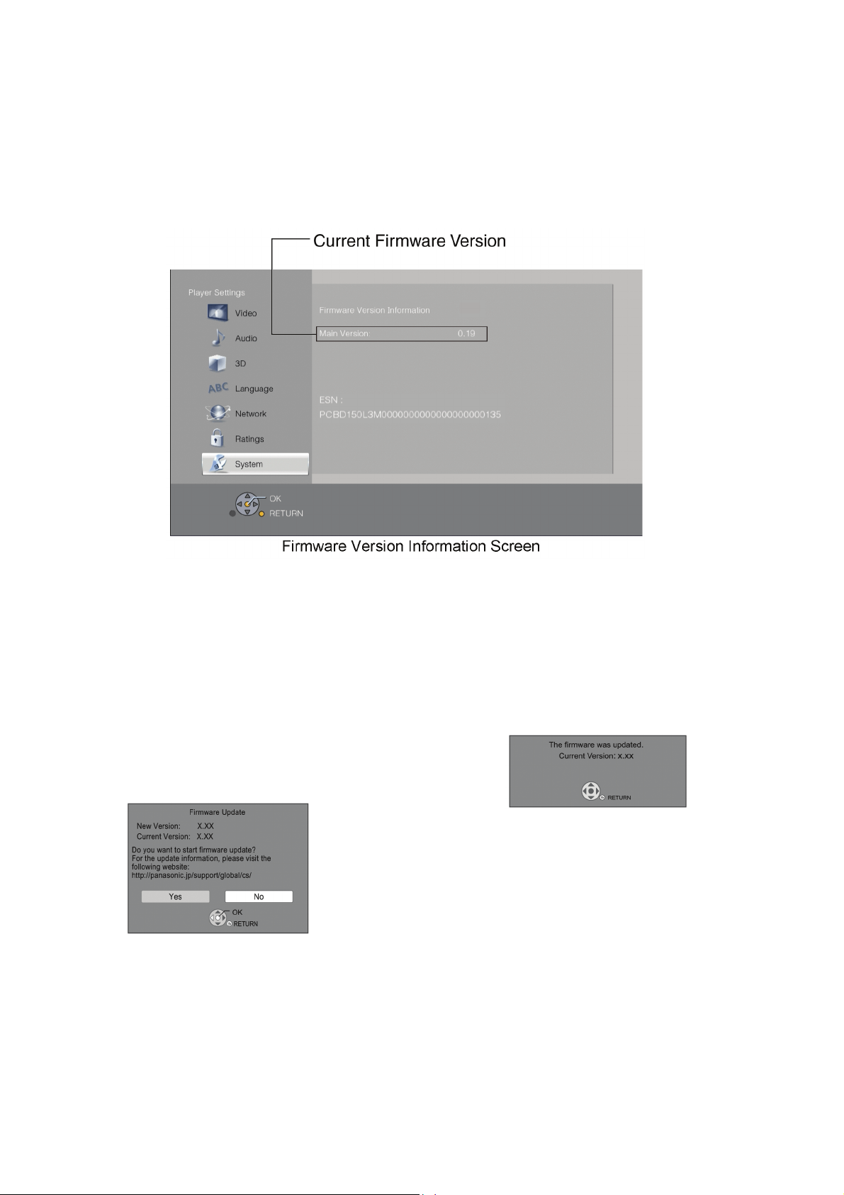
3.4.1. Confirmation of the Firmware Version
Perform following steps to checking the firmware version currently installed in the unit.
1. Turn the unit on and wait the Home screen is displayed.
2. Select [Setup] → [Player Settings] → [System] → [System Information] → [Firmware Version Information].
3. Firmware Version Information screen is displayed.
3.4.2. Updating Firmware
This unit has 2 updating method, one way to update via the internet, the other way to update using CD-R or USB device which is
stored pre-downloaded firmware update file.
3.4.2.1. Updating firmware via the internet
Occasionally, Panasonic may release updated firmware for this
unit that may add or improve the way a feature operates. These
updates are available free of charge.
This unit is capable of checking the firmware automatically
when connected to the Internet via a broadband connection.*
When a new firmware version is available, the following
message is displayed.
You can also download the latest firmware from the following
website and store it to a USB device to update the firmware.
http://panasonic.jp/support/global/cs/
(This site is in English only.)
DO NOT DISCONNECT the unit from the AC power or perform
any operation while the update takes place.
After the firmware is installed, unit will restart and the following
screen will be displayed.
12
Page 13

3.4.2.2. Updating firmware using the USB device
When updating firmware using USB device, perform following procedures.
(When using CD-R instead of USB device, perform same procedures)
1. Download the latest firmware file of the unit
The latest firmware required for version-up can be downloaded from "Support Information from AVC"
web-site in "TSN system".
Click file name to download.
After download, click file to decompress.
2. Decompress the downloaded file.
The decompressed file will be named as "PANA_DVD.FRM".
Copy the file to root folder of the USB device.
(If using CD-R instead of USB device, burn the file to a blank CD-R by writing software.)
13
Page 14
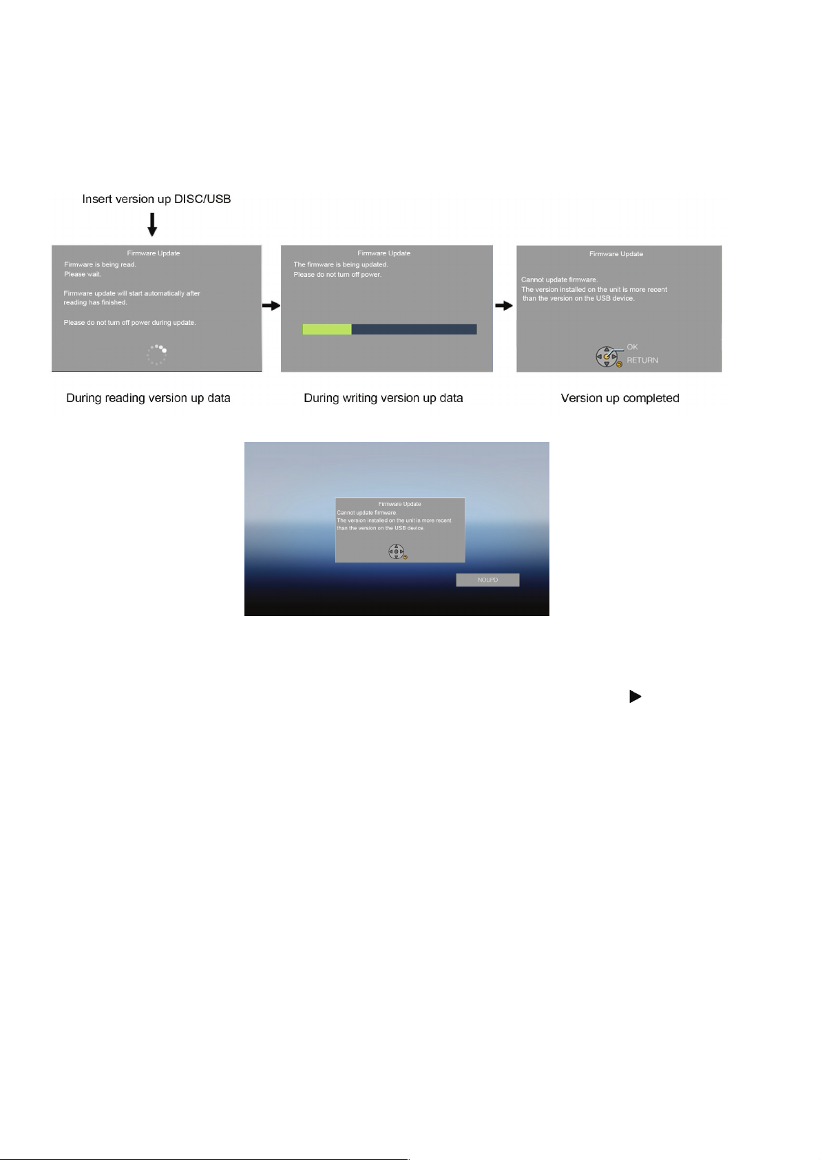
3. Update the unit
(1)Turn the unit power on.
(2)After the home screen is displayed, insert the USB device stored downloaded latest firmware file to front USB port of the
unit.(or set the CD-R into the unit and playback it.)
(3)The screens are displayed as below.
[Screen transition]
(if the following screen is displayed, the unit has already been update the latest version of firmware.)
Firmware update is not needed
(4)Remove the USB device (or the CD-R) and press the [POWER] button to turn the unit off.
(5)Turn the unit on and home screen is displayed, the firmware update is completed.
NOTE:
After updating finishing, press [Y] [B] [OK] into Disclosure mode and hold the right button of remote control [ ]
displayed, then long press [OK] and make factory setting. (Refer to "3.3.1".)
until [08FIN] is
14
Page 15

4 Specifications
Power supply: DC12V, 0.8A(DC IN terminal)
Power consumption: Approx. 11W
in standby mode: Approx. 0.5W
in Network standby mode: Approx. 3.5W
Operating temperature range: +5°C to +35°C (+41 to +95°F)
Operating humidity range: 10% to 80%RH (no condensation)
Signal system: PAL /NTSC
HDMI AV output:
Output connector: TypeA (19pin)
1 system
USB slot:
USB2.0: 1 system
Ethernet:
10BASE-T/100BASE-TX: 1 system
Media:
Playable disc:
BD-Video
(Blu-ray 3D, BD-LIVE,
BONUSVIEW):
BD-RE: Version3 (Single Layer/Dual Layer),
BD-R: Version2 (Single Layer/ Dual
DVD-R:
DVD-R DL:
DVD-RW: DVD-Video format(*1), DVD Video
+R: Video(*1), AVCHD format(*1)
+R DL: Video(*1), AVCHD format(*1)
+RW: Video(*1), AVCHD format(*1)
DVD-Video: DVD-Video format
CD-Audio: CD-DA
CD-R/CD-RW:
*1: Finalizing is necessary.
*2: ISO9660 level 1 or 2 (except for extended formats), Joliet.
This unit is compatible with multi-session.
This unit is not compatible with packet writing.
*3: UDF1.02 without ISO9660, UDF1.5 with ISO9660.
*4: UDF2.5.
*5: MPEG-4 ASP Level 4.
MPEG2 Video, AAC-LC, MP3, Dolby Digital audio, DTS,
PCM, FLAC and Vorbis can be decoded.
*6: Subtitle text support.
SD card: no SD card slot
USB device:
USB Standard: USB2.0 High Speed
Format:
Contents:
BD-ROM Part3 Version 2.4
JPEG, MPO:MP3, FLAC,
WAV, AAC, WMA, DSD, ALAC
Layer), MKV(*4,*5,*6),
:MP3, FLAC, WAV, AAC, WMA,
DSD, ALAC
DVD-Video format(*1), DVD Video
Recording format(*1), AVCHD
format(*1), JPEG(*2), MPO(*2),
MP3(*2), WAV(*2), FLAC(*2),
AAC(*2), WMA(*2),
MKV(*2,*3,*5,*6), Xvid(*6), DSD,
ALAC
DVD-Video format(*1), DVD Video
Recording format(*1), AVCHD
format(*1), JPEG(*2), MPO(*2),
MP3(*2), WAV(*2), FLAC(*2),
AAC(*2), WMA(*2),
MKV(*2,*3,*5,*6), Xvid(*6), DSD,
ALAC
Recording format(*1), AVCHD
format(*1)
CD-DA, JPEG(*2),
WAV(*2), FLAC(*2), AAC(*2),
WMA(*2), MKV(*2,*5,*6), Xvid(*6),
ALAC
FAT12, FAT16, FAT32, NTFS
Xvid(*6)
MPO(*2),
MP3(*2),
JPEG:
CD-R/RW, BD-RE, DVD-R, USB device:
Pixcels: 34x34~8172x8172
Sub Sampling: 4:2:2, 4:2:0
Motion JPEG not supported
MP3:
BD-R/RE, CD-R, CD-RW, DVD-R, USB device:
Compression rate: 32kbps~320kbps
Sampling rate: 44.1kHz, 48kHz
AVCHD (H.264):
DVD: AVCHD format V1.0
HDMI: 480p(525p)/1080i(1125i)/
720p(750p)/1080p(1125p)
HDMI (V.1.4a with 3D, Content
Type)
This unit supports “HDMI-CEC”
function.
Playable disc:
BD-ROM (SL/DL): Compliant Ver. 1.3
(SL: Single Layer/DL: Dual Layer)
BD-RE (SL/DL): BD-MV
(SL: Single Layer/DL: Dual Layer)
BD-R (SL/DL): BD-MV
(SL: Single Layer/DL: Dual Layer)
DVD-ROM (SL/DL): DVD-Video
(SL: Single Layer/DL: Dual Layer)
DVD-R: DVD-Video, DVD-VR
DVD-R(DL): DVD-Video, DVD-VR
DVD-RW: DVD-Video, DVD-VR
+R: Video
+R(DL): Video
+RW: Video
CD: CD-DA, CD-R/RW
Optical pick-up:
Wave length: System with 1 lenses
790 nm (CDs)/660 nm (DVDs)/
405 nm (BDs)
LASER Specification:
Class I LASER Product
Wave length: 790nm (CDs)/660 nm (DVDs)/405
nm (BDs)
Laser power: No hazardous radiation is emitted
with the safety protection
Regional Code: DVD: #2
BD: Region B
Dimensions:
245mm(W) [Approx. 9 10/16''(W)]
38.5mm(H) [Approx. 1 8/16''(H)]
175mm(D) [Approx. 6 14/16''(D)]
Mass: Approx. 0.8 kg ( 1.7 lbs)
Solder: This model uses lead free
solder(PbF).
Note: Specifications are subject to
change without notice.
15
Page 16
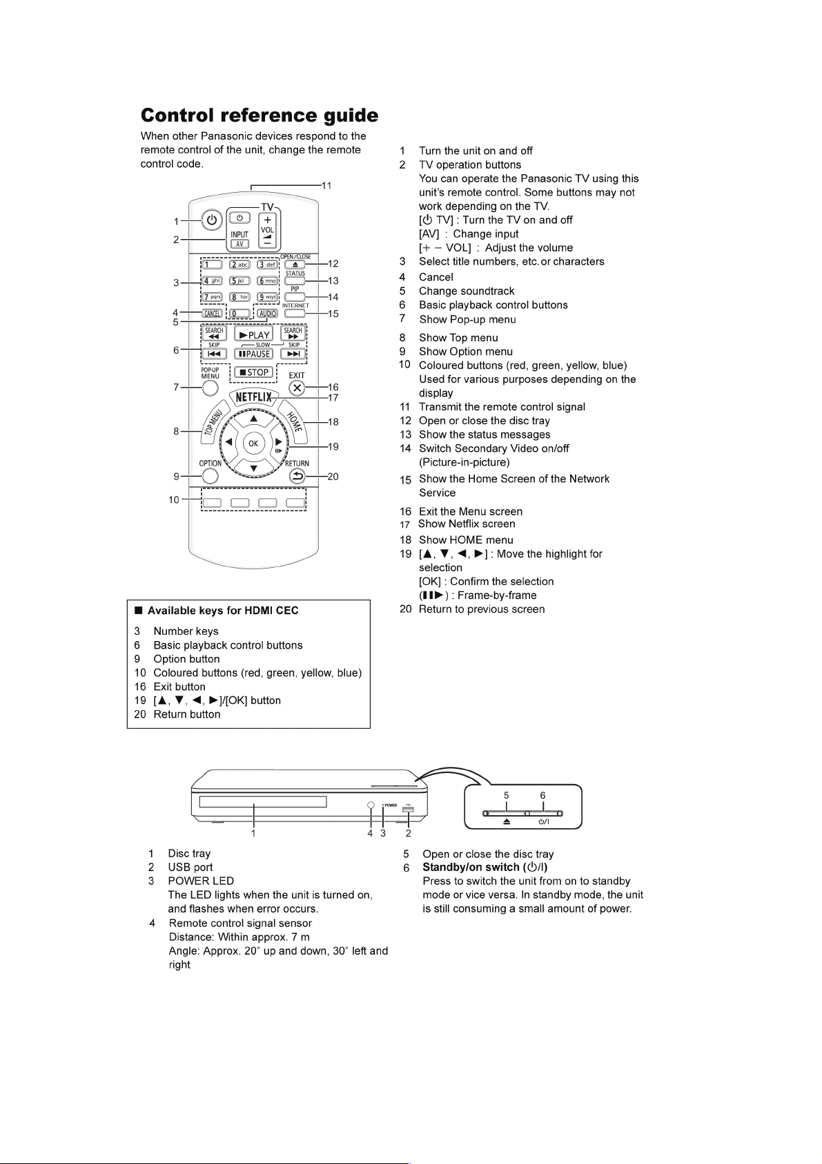
5 Location of Controls and Components
16
Page 17
6 Operating Instructions
6.1. Taking out the Disc from BD-Drive Unit when the Disc cannot be ejected by OPEN/CLOSE button
6.1.1. Forcible Disc Eject
1. Turn on the power, press and hold [OK], [B] and [Y] on the remote control at the same time for more than 5 seconds.
"00RET" is displayed on the TV.
2. Repeatedly press [ ] on the remote control or [POWER] on the unit until "06FT0" is displayed on the TV.
3. Press [OK] on the remote control or [OPEN/CLOSE] on the unit.
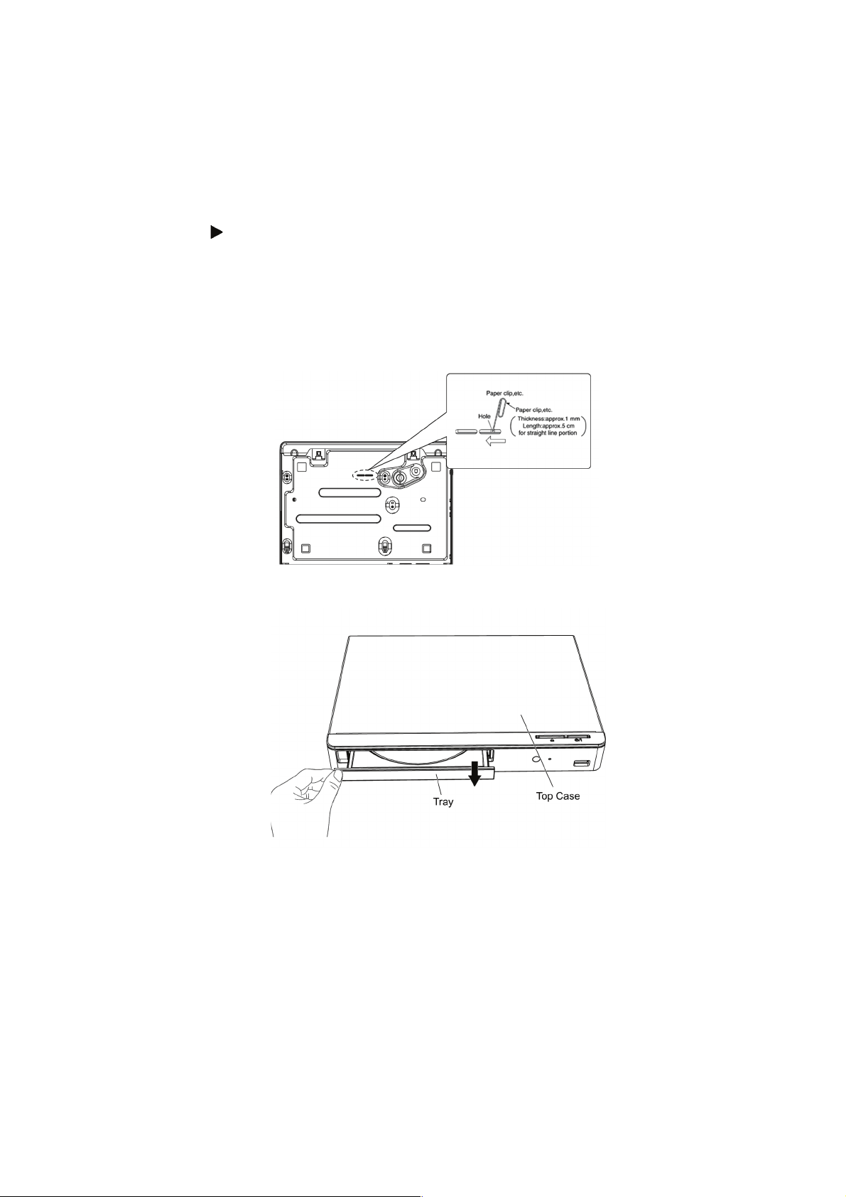
6.1.2. When the Forcible Disc Eject can not be done.
1. Turn off the power and pull out AC cord.
2. Put deck so that bottom can be seen.
3. Insert the Paper clip, etc. into the hole on the bottom of BD Drive and slide the Paper clips, etc. in the direction of the arrow to
eject tray slightly.
4. Put deck upward, and pick out Tray by finger.
17
Page 18
7 Service Mode
7.1. Special Mode Setting and Service mode
7.1.1. Self-Diagnosis Functions
Self-Diagnosis Function provides information for errors to service personnel by “Self-Diagnosis Display” when any error has
occurred.
U**
and F** are stored in memory and held.
You can check latest error code by transmitting [0] [1] of Remote Controller in Service Mode.
Automatic Display on TV will be cancelled when the power is turned off or AC input is turned off during self-diagnosis display is ON.
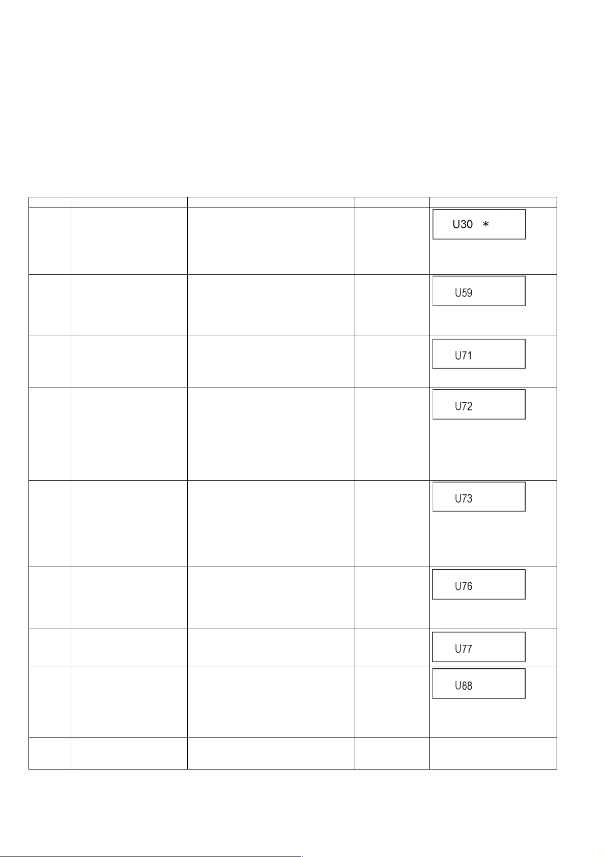
Error Code Diagnosis contents Description Monitor Display Automatic TV display
U30 Remote control code error Display appears when main unit and remote
controller codes are not matched.
U59 Abnormal inner temperature
detected
U71 HDMI incompatible error
(HDMI incompatible)
U72 HDMI connection error
(communication error)
U73 HDMI connection error
(authentication error)
U76 Connection error This error is displayed when equipment such
U77 Illegal disc error This error is displayed when it becomes
U88 Restoration is operation.
(When the disc is in the disc
tray)
F00 No error information Initial setting for error code in memory (Error
Display appears when the drive temperature
exceeds 70°C.
The power is turned off forcibly.
For 30 minutes after this, all key entries are
disabled.
The event is saved in memory as well.
Display this error when the equipment (compatible with DVI such as TV, amplifier etc.)
connected to the unit by HDMI is incompatible
with HDCP (High-bandwidth Digital Content
Protection).
Display this error when there are any communication problems with the unit and the equipments (TV, amplifier ect.) connected to the
unit by HDMI. (or when there is a problem
with the HDMI cable).
The display disappears only when the
connection is released. Neither the button
operation nor the passage of the fixed time
disappear the display.
When authentication error occurs while the
equipments (TV, amplifier etc.) are connected
by HDMI. (or when there is a problem with the
HDMI cable)
The display disappears only when the connection is released. Neither the button operation nor the passage of the fixed time
disappear the display.
as TVs or amplifiers connected to the unit
with the HDMI cable do not correspond to the
copyright protection. (The BD/DVD video
where the copyright is protected cannot be
played.)
impossible to reproduce because of copyright
illegal information.
This error is displayed when there is a disc in
the disc tray or abnormality is confirmed
during playback. It is shown that the
restoration to return the main unit operation
normally is operating. It becomes possible to
use as soon as not the breakdown but the
U88 display disappears.
code Initialization is possible with error code
initialization and main unit initialization).
No display
* is remote controller code of the
main unit.
Display for 5 seconds.
No display
"U59" is displayed for 30 minutes.
No display
No display
"U72" display disappears when
error has been solved by Power
OFF/ON of connecting equipment
or by inserting/removing of HDMI
cable.
No display
"U73" display disappears when
error has been solved by Power
OFF/ON of connecting equipment
or by inserting/removing of HDMI
cable.
No display
No display
No display
Display for 30 seconds.
No display No display
18
Page 19
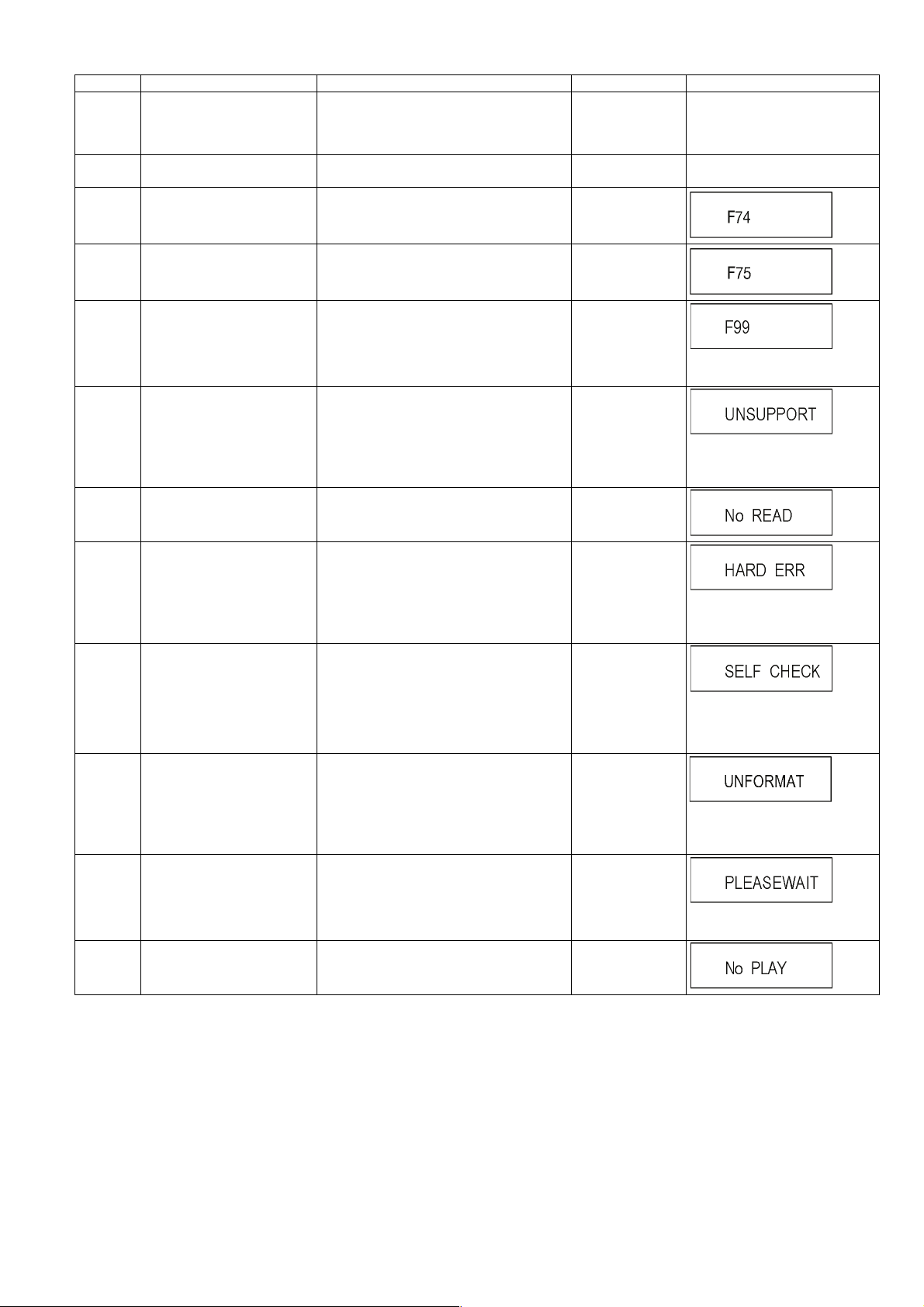
Error Code Diagnosis contents Description Monitor Display Automatic TV display
F34 Initialization error When initialization error is detected after start-
ing up main microprocessor, the power is
turned off automatically. The event is saved in
memory.
F58 Drive hardware error When drive unit error is detected, the event is
saved in memory.
F74 HDMI Device Key Communica-
tion error
This error is displayed when the information
error is occurred at HDMI device key loading.
No display No display
No display No display
No display
F75 HDMI Device Key Loading
error
F99 Hang-up Displayed when communication error has
UNSUPPORT
NO READ Disc read error *A disc is flawed or dirty.
HARD
ERR
SELF
CHECK
UNFORMAT
PLEASE
WAIT
No PLAY When there is a viewing restric-
Unsupported disc error *An unsupported format disc was played,
Drive error The drive detected a hard error. “BD drive error.”
Restoration operation Since the power cord fell out during a power
Unformatted disc error This error is displayed when the unformatted
Unit is in termination process Unit is in termination process now.
tion on a BD-Video or
DVD-Video.
This error is displayed when the key of loaded
is illegal at HDMI device key loading.
occurred between Main microprocessor and
Timer microprocessor.
although the drive starts normally.
*The data format is not supported, although
the media type is supported.
*Exceptionally in case of the disc is dirty.
*A poor quality failed to start.
*The track information could not be read.
failure or operation, it is under restoration
operation.
*It will OK, if a display disappears automatically. If a display does not disappear, there is
the possibility that defective Digital P.C.B. /
BD Drive.
DVD-RAM/DVD-RW or the DVD-RW
recorded by another make of recorder is
inserted.
[BYE] is displayed and power will be turned
off.
Rating password is set. No display
No display
No display
"F99" is displayed utill the
[POWER] key is pressed.
“This disc is
incompatible.”
It is displayed for 5 seconds.
The character indication flows
sideways.
“Cannot read.
Please check the
disc.”
It is display for 5 seconds.
The character indication flows
sideways.
No display
The character indication flows
sideways.
No display
This disc is not formatted properly.
Format the disc in DISC
MANAGEMENT?
No display
The character indication flows
sideways.
19
Page 20
7.1.2. Special Modes Setting
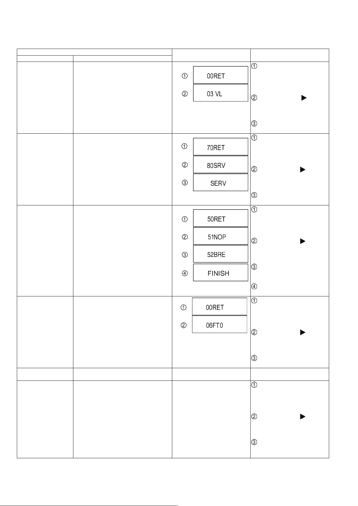
Item
Mode name Description
Rating password The audiovisual level setting password is
initialized to Level 8.
Service Mode Setting every kind of modes for servicing.
*Details are described in 7.1.3. Service Mode
at a glance.
BD-ROM history cleaning <Persistent Storage> of BD-ROM standard is
cleaned.
Forced disc eject Removing a disc that cannot be ejected.
The tray will open and unit will shift to P-off
mode.
While Demonstration Lock is being set, this
Forced disc eject function is not accepted.
Forced power-off When the power button is not effective while
power is ON, turn off the power forcibly.
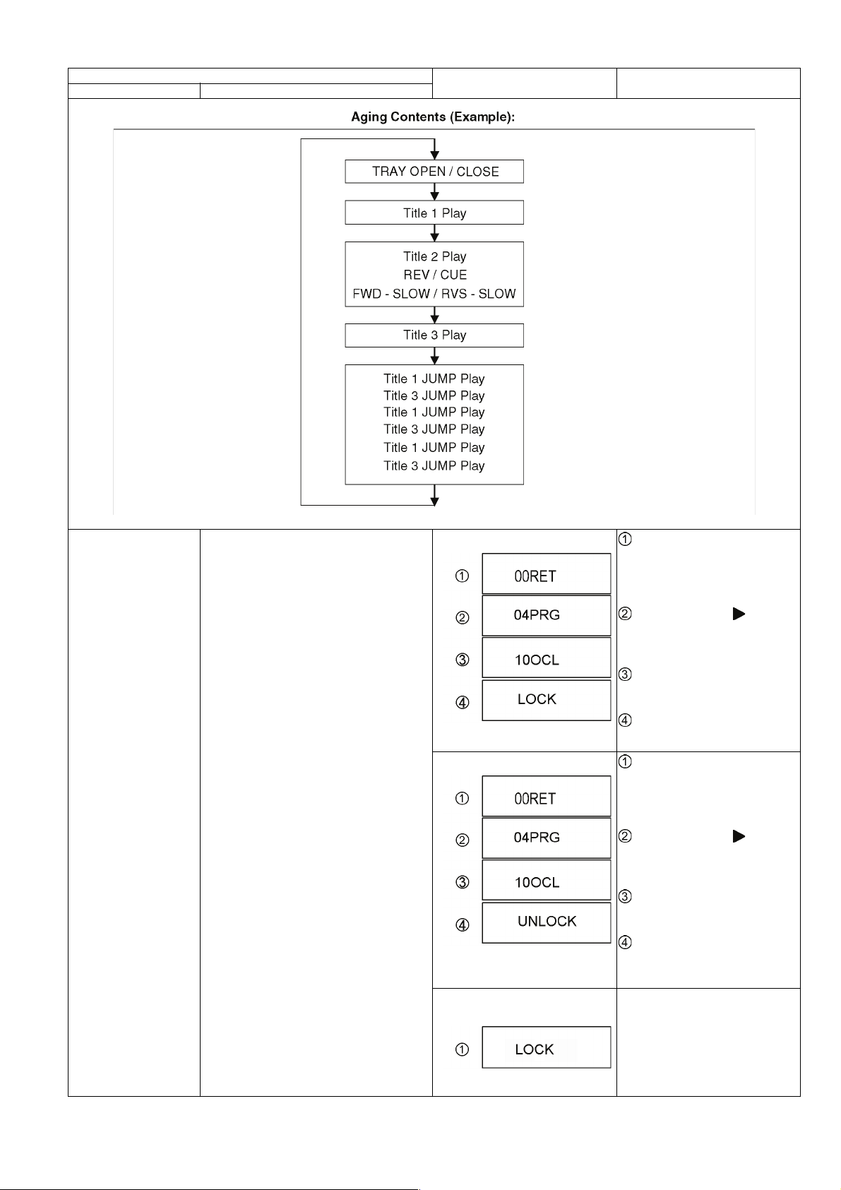
Aging Perform sequence of modes as * Aging
Description shown below continually.
TV display Key operation
While the unit is on, press and
hold [OK], [B] and [Y] on the remote
control at the same time for more
than 5 seconds.
-"00RET" is displayed on the TV.
Repeatedly press
remote control or [POWER] on the
unit until "03 VL" is displayed on the
TV.
Press [OK] on the remote control
or [OPEN/CLOSE] on the unit.
While the unit is on, press and
hold [5], [9] and [R] on the remote
control at the same time for more
than 5 seconds.
-"70RET" is displayed on the TV.
Repeatedly press
remote control or [POWER] on the
unit until "80SRV" is displayed on
the TV.
Press [OK] on the remote control
or [OPEN/CLOSE] on the unit.
While the unit is on, press and
hold [6], [7] and [Y] on the remote
control at the same time for more
than 5 seconds.
-"50RET" is displayed on the TV.
Repeatedly press
remote control or [POWER] on the
unit until "51NOP" is displayed on
the TV.
Press and hold [STOP] on the
remote control until "52BRE" is displayed on the TV.
Press [OK] on the remote con-
trol or [OPEN/CLOSE] on the unit.
While the unit is on, press and
hold [OK], [B] and [Y] on the remote
control at the same time for more
than 5 seconds.
-"00RET" is displayed on the TV.
Repeatedly press
remote control or [POWER] on the
unit until "06FT0" is displayed on
the TV.
Press [OK] on the remote control
or [OPEN/CLOSE] on the unit.
Display in P-off mode. Press [POWER] key over than 10
Display following the then mode.
seconds.
While the unit is on, press and
hold [5], [9] and [R] on the remote
control at the same time for more
than 5 seconds.
-"70RET" is displayed on the TV.
Repeatedly press
remote control or [POWER] on the
unit until "81AIG" is displayed on the
TV.
Press [OK] on the remote control
or [OPEN/CLOSE] on the unit for at
least 3 seconds.
[ ] on the
[ ] on the
[ ] on the
[ ] on the
[ ] on the
20
Page 21
Item
Mode name Description
TV display Key operation
Demonstration
lock / unlock
Ejection of the disc is prohibited.
The lock setting is effective until unlocking the
tray and not released by Main unit initialization of service mode.
*When lock the tray.
"LOCK" is displayed for 3 seconds.
*When lock the tray.
"UNLOCK" is displayed for 3 seconds.
*When press [OPEN/CLOSE] key
while the tray being locked.
While the unit is on, press and
hold [OK], [B] and [Y] on the remote
control at the same time for more
than 5 seconds.
-"00RET" is displayed on the TV.
Repeatedly press
remote control or [POWER] on the
unit until "04PRG" is displayed on
the TV.
Press and hold [STOP] on the
remote control until "10OCL" is displayed on the TV.
Press [OK] on the remote con-
trol or [OPEN/CLOSE] on the unit.
While the unit is on, press and
hold [OK], [B] and [Y] on the remote
control at the same time for more
than 5 seconds.
-"00RET" is displayed on the TV.
Repeatedly press
remote control or [POWER] on the
unit until "04PRG" is displayed on
the TV.
Press and hold [STOP] on the
remote control until "10OCL" is displayed on the TV.
Press [OK] on the remote con-
trol or [OPEN/CLOSE] on the unit.
Press [OPEN/CLOSE] key while the
tray is being locked.
[ ] on the
[ ] on the
Display "LOCK" on the screen.
21
Page 22
Item
Mode name Description
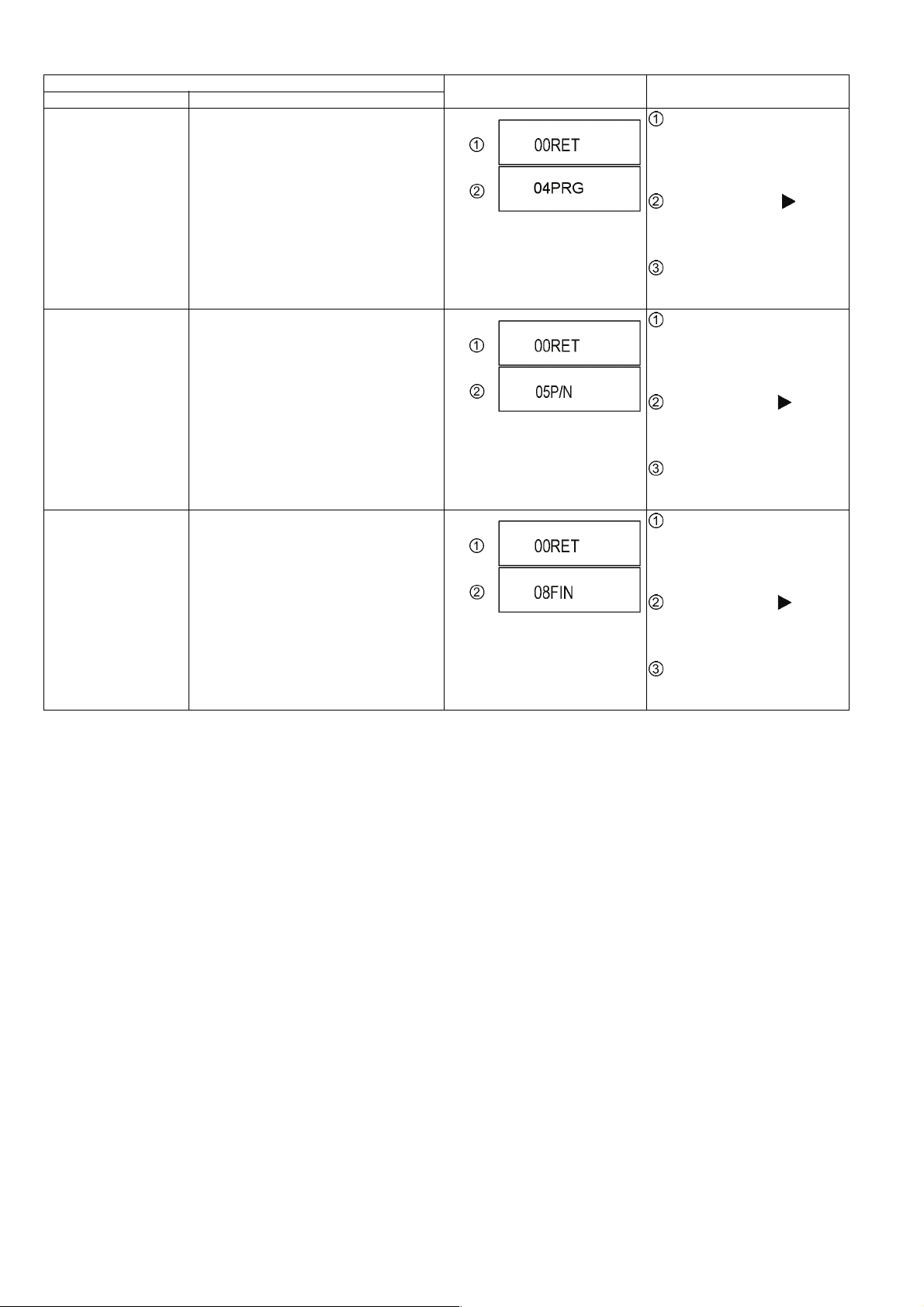
Progressive initialization The progressive setting is initialized to inter-
lace.
PAL/NTSC switch The signal system is switched to PAL or
NTSC.
Default setting The date of Menu, Mode and EEPROM set-
ting, etc. is set to the default condition in factory.
TV display Key operation
While the unit is on, press and
hold [OK], [B] and [Y] on the remote
control at the same time for more
than 5 seconds.
-"00RET" is displayed on the TV.
Repeatedly press
remote control or [POWER] on the
unit until "04PRG" is displayed on
the TV.
Press and hold [OK] on the
remote control or [OPEN/CLOSE]
on the unit for at least 3 seconds.
While the unit is on, press and
hold [OK], [B] and [Y] on the remote
control at the same time for more
than 5 seconds.
-"00RET" is displayed on the TV.
Repeatedly press
remote control or [POWER] on the
unit until "05P/N" is displayed on the
TV.
Press and hold [OK] on the
remote control or [OPEN/CLOSE]
on the unit for at least 3 seconds.
While the unit is on, press and
hold [OK], [B] and [Y] on the remote
control at the same time for more
than 5 seconds.
-"00RET" is displayed on the TV.
Repeatedly press
remote control or [POWER] on the
unit until "08FIN" is displayed on the
TV.
Press and hold [OK] on the
remote control or [OPEN/CLOSE]
on the unit for at least 3 seconds.
[ ] on the
[ ] on the
[ ] on the
22
Page 23
7.1.3. Service Mode at a glance
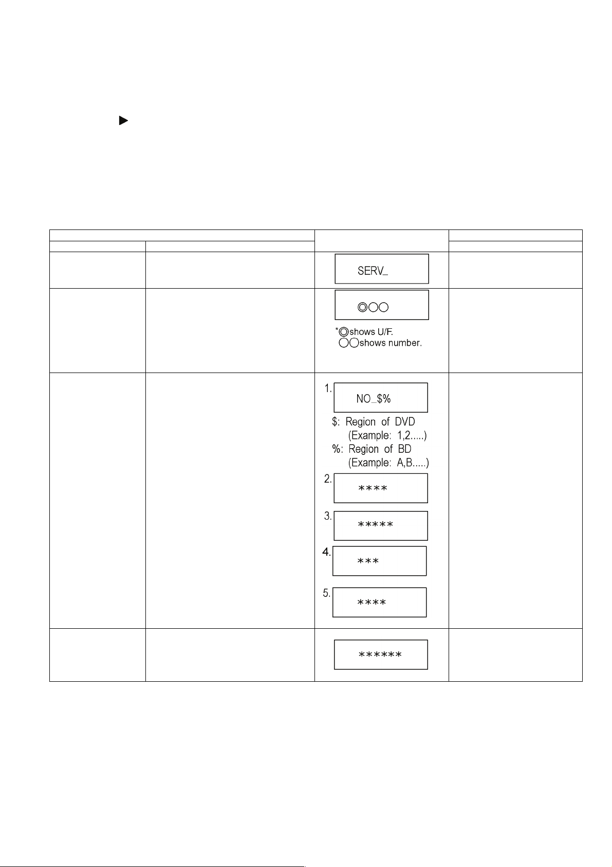
Information necessary for service can be displayed.
Service mode setting:
1. Turn the power on.
2. Press the [5] [9] and [R] button simultaneously for five seconds, then [70RET] is displayed on TV.
3. Press the
4. Press the [OK] button.
5. It is displayed on TV as [SERV]: It is shown to have entered the service mode.
6. The command is transmitted by attached remote control.
Method of making clear service mode: Press the power button (power off).
The display of information to each command is as follows.
NOTE:
Do not use it excluding the designated command.
[ ] button to select until [80SRV] is displayed on TV.
Item
Mode name Description (Remote controller key)
Release Items Item of Service Mode executing is cancelled. Press [0] [0] or [Return] in service
Error Code Display Last Error Code of U/F held by Timer is dis-
played on TV.
*Details are described in
7.1.1. Self-Diagnosis Functions.
If any error history does not exist,
[F00] is displayed.
ROM Version Display The display contents are switched over every
5 seconds.
1. Region code
2. Main firm version
3. Boot View version
4. Timer firm version
5. Drive firm version
TV display
mode.
Press [0] [1] in service mode
Press [0] [2] in service mode
Key operation
Display Engineering
Adjusted Value
Displays the Engineering Adjusted Value. Press [0] [9] in service mode.
23
Page 24

Item
Mode name Description (Remote controller key)
Laser Used Time
Indication
Check laser used time (hours) of drive.
(****) is the used time display in
hour. Laser used time of BD/DVD/
CD in Playback mode is counted.
TV display
Press [4] [1] in service mode.
Key operation
24
Page 25

Item
Mode name Description (Remote controller key)
BD Drive last error BD Drive error code display. 1. Error Number is displayed for 5
seconds.
2. Time when the error has occurred
is display for 5 seconds.
YY: Year
MM: Month
DD: Date
3. Last drive error (1/2) is displayed
for 5 seconds.
00 : Bad disc
03 : Bad disc
04 : Bad disc or drive malfunction
4. Last drive error (2/2) is displayed
for five seconds.
TV display
Press [4] [2] in service mode.
Key operation
5. Error occurring disc type is displayed for 5 seconds.
25
Page 26

Item
Mode name Description (Remote controller key)
TV display
Key operation
6. Disc maker ID is displayed for 5
seconds.
26
In case that the maker cannot be
identified, display is blackout.
Page 27

Item
Mode name Description (Remote controller key)
7. Factor of drive error (hexadecimal) occurring is left displayed.
TV display
Key operation
8. When the last error doesn't exist .
PD Balance Measuring the PD balance.
Formalize FE (0~99999)
FE symmetry (0~99999)
Number of reflection surface (0~2)
Measurements failure
CEC (H) Output The CEC terminal high output of HDMI. Press [5] [5] in service mode.
1.Insert the Panasonic BD-VIDEO
SL Disc(Ver 1.0/Ver 2.0) into the
tray.
(Incompatible with other media)
2.Press [4] [8].
27
Page 28

Item
Mode name Description (Remote controller key)
CEC (L) Output The CEC terminal low output of HDMI. Press [5] [6] in service mode.
TV display
Key operation
Manufacturing Date Read out the manufacturing date of the unit.
Save the error history to
USB storage device
Update Engineering
Adjusted value
The error and user operation history of the
remote control are saved to the USB storage
device.
NANDFlash is updated with the 6-figure input
value of a remote control.
YY: Year
MM: Month
DD: Date
The USB storage device cannot be
recognized
During saving
Save end
Press [6] [1] in service mode.
Press [6] [9] in service mode.
Press [7] [2] in service mode.
Tray OPEN/CLOSE Test The BD Drive tray is opened and closed
repeatedly.
Delete the Laser Used
Time
Laser used time information stored in the
memory of the unit is deleted.
Input the 6 digits adjust value, that
is in the Drive or OPU replacement
part,with the remote control's number keys in the service mode.
When register successful:
When register fail:
Press [9] [1] in service mode.
*When releasing this mode, pull out
AC cord.
"*" is number of open/ close cycle
times.
Press [9] [5] in service mode.
Delete the Last Drive
Error
Laser Drive Error information stored on the
BD Drive is deleted.
Press [9] [6] in service mode.
28
Page 29

Item
Mode name Description (Remote controller key)
Delete the Error History Error History information stored on the unit is
deleted.
TV display
Press [9] [7] in service mode.
Key operation
Initialization of Error code Last Error Code information stored by timer is
deleted. (Write in F00)
Initialization of the
Service Mode
Release Service Mode Release Service Mode and turns the Power
Last Drive Error, Error History and Error code
information stored on the unit are initialized to
factory setting.
Off.
Press [9] [8] in service mode.
Press [9] [9] in service mode.
Display in STOP (SS) mode. Press [POWER] button on the front
panel or Remote controller in service mode.
29
Page 30

8 Service Fixture & Tools
Part Number Description Pcs Compatibility
SVKZ000001 Lead Free Solder (0.3mm/100g Reel) New
SVKZ000002 Lead Free Solder (0.6mm/100g Reel) New
SVKZ000003 Lead Free Solder (1.0mm/100g Reel)) New
RFKZ0316 Solder Remover (Lead free low temperature Solder/50g) Same as BDT360 Series
RFKZ0328 Flux Same as BDT360 Series
* The above parts are supplied by AVC-CSC-SPC.
30
Page 31

9 Disassembly and Assembly Instructions
9.1. Unit
9.1.1. Disassembly Flow Chart
The following chart is the procedure for disassembling the casing and inside parts for internal inspection when carrying out the
servicing.
To assemble the unit, reverse the steps shown in the chart below.
9.1.2. P.C.B. Positions
31
Page 32

9.1.3. Top Case
1. Remove the 3 Screws (A).
2. Slide the Top Case rearward and open the both ends at
rear side of the Top Case a little and lift the Top Case in
the direction of the arrows.
9.1.4. Front Panel Ass'y
9.1.4.1. Tray Top
1. Put deck so that bottom can be seen.
2. Insert the Paper clip, etc. into the hole on the bottom of
BD Drive and slide the Paper clips, etc. in the direction of
the arrow to eject tray slightly.
3. Unlock 2 tabs to remove the tray top from the tray section.
32
Page 33

9.1.4.2. Front Panel
1. Unlock 6 tabs (A)-(E) turn. Pull with the Front Panel in the
direction of your side.
NOTE:
1. The LED SHEET is easy to fall off when removing the
front panel, please be careful when disassembling.
9.1.5. BD Drive
1. Remove the OPU FFC, and isolate it with an ESD prevention bag (RPFC0114) to prevent the laser diode from
the ESD damage.
2. Remove the FFC(A), FFC(B), FFC(C).
3. Remove the 2 Screws (A), remove 2 tabs (B) of BD Drive
in the direction of the arrow, to remove BD Drive.
2. When installing the FUNCTION BUTTON, insert the front
half part of FUNCTION BUTTON into the front hole
obliquely, and then press down till claw, snaps in to place.
NOTE:
The metal side of the FFC(C) should be inserted in the
direction of the Front Panel during installation as shown.
33
Page 34

9.1.6. Digital and Operation P.C.B.
1. Remove the 2 Screws (A) to remove Digital and Operation P.C.B..
2. Desoldering the Digital P.C.B. end of solder joint, and
then removing the Operation P.C.B..
9.2. Drive Unit
9.2.1. Tray Unit
1. Insert the Paper clips, etc. into the hole of the bottom
side, and slide it to the direction of arrow until it can be.
2. Pull the Tray Unit to the direction of arrow until it can be.
NOTE:
After removing the digiboard and Front Panel, do not
bend the cable repeatedly shown in the illustration, in
case of breaking off.
3. Insert the paper clips, screw drivers, etc. to open the 2
tabs, and pull the Tray Unit.
34
Page 35

Notes when attaching the tray:
• Push Slide cam to the left side slightly, and make sure
the tray band is between the two posts of Slide cam
when attaching the tray.
3. Remove the Pulley Gear and Belt.
9.2.3. Slide Cam, Traverse Base
1. Perform the step "9. 2. 2. Pulley Gear, Belt".
2. Open the connector lock, and disconnect the FFC.
9.2.2. Pulley Gear, Belt
1. Perform the step "9. 2. 1. Tray Unit".
2. Push the Post to the direction of arrow by using the slotted screwdriver.
3. Turn over the drive unit then unlock the 2 tabs.
35
Page 36

4. Slide the FFC and remove it.
5. Slide the Slide Cam to right, then lift up the Traverse
base.
6. Remove the Traverse base with spreading the 2 hooks to
direction of arrows.
7. Slide the Slide Cam to right, then open the 2 tabs and
remove the Slide Cam.
9.2.4. Drive Gear and Loading Motor Unit
1. Perform the step "9. 2. 3. Slide Cam, Traverse Base".
2. Remove the Drive Gear.
3. Turn over the Drive Unit, then remove the Loading Motor
unit with spreading the 2 tabs.
36
Page 37

4. Pull out the SW FFC.
5. Push the tab to the direction of arrow by using the slotted
screwdriver and slide the SW Ass'y to remove.
37
Page 38

9.2.5. Grease
38
Page 39

9.3. Disassembly from the traverse unit, assembly of the optical pick-up unit, and precautions on ESD-preventive
9.3.1. Disassemly
1. Before removing the optical pick-up unit, please apply an
ESD prevention bag(RPFC0114) to the OPU FFC, and
weld the short-circuit solder.
a. Set the temperature of iron is 350°C.
b. When using the iron head,do not apply a force more
than 1N to the pad. Do not touch any other components around the welding spot.
c. Welding should be applied less than 3 seconds.
2. Remove the connector, and take out the OPU FFC.
4. Unlock 2 Damper Springs of the Screw Shaft side.
5. Slightly lift up the Drive Shaft (A) by the end, pull it out of
the Damper Spring, and remove the Drive Shaft (A) as
well as the Optical Pick-Up Unit with the Nut Piece Unit.
3. Slide the Middle Base horizontal and remove the Middle
Base from the Traverse Unit.
39
Page 40

6. Remove 1 screw (A), and remove the Nut Piece Unit.
9.3.2. Assembly
1. Attach the Nut Piece Unit sufficiently onto the Optical
pickup Unit, and tighten 1 screw (A).
NOTE:
1. In this action, finger stab needs to be put on. Do not
touch any parts other than the positions marked in the
Figure 1.
40
Page 41

2. After applying a small amount of lubricants to the both
ends of Drive Shaft (A), insert the Optical Pick-Up Unit
into the Drive Shaft (A), then insert them into shaft hole of
the base.
Attach the other side of Optical Pick-Up on the Drive
Shaft (B), then set 2 damper springs and lock the drive
shaft (A) to the base.
4. Insert FFC, and desolder the solder spot.
a. Use the iron head with an angle as shown in
Fig,remove the solder in the direction as shown.
b. Set the temperature of iron below 350° C.
c. When using the iron head,do not apply a force more
than 1N to the pad. Do not touch any other compo-
nents around the welding spot.
d. Welding should be applied less than 3 seconds.
Caution:
Do not stick any foreign bodies to the shaft duringassembly.
3. Attach the Middle Base to the traverse unit.
41
Page 42

9.3.3. How to Clean the Lens of Optical Pick-UP
After performing the step "9. 2. 3. Slide Cam, Traverse Base", clean the lens of the Optical Pick-UP.
42
Page 43

9.3.4. How to Clean up the Turntable
When "NoREAD" is displayed in TV display, after performing the step "9. 2. 3. Slide Cam, Traverse Base", clean up the Turntable
according to the following steps.
1. Blow the dust from the Turntable in the blower.
(Do not strongly blow it.)
2. Put one drop of isopropyl or ethyl alcohol to clean cotton swab.
(Using a fresh cotton swab does not use chemicals or additives.)
3. Using the cotton swab, wipe out the dust on the Turntable.
(Be careful not touching the surface of Turntable directly.)
43
Page 44

9.4. Adjustment of BD Drive
9.4.1. Repair Flowchart
44
Page 45

9.4.2. Adjustment
9.4.2.1. The adjustment value setting of Drive Unit/OPU replacement
1. Power ON
2. Press and hold [5] [9] [Red] button on the remote control concurrently for 5 sec.
3. Display "70RET"
4. Press
5. It reboots automatically.
6. Display "SERV" (Service Mode)
7. Input the number of 6 sdigits adjust value that is wrote on
8. Input [7] [2] in "SERV" then display "DQR" total 6 digits
9. It will be OK if "DQR OK"is displayed.
10. Input [0] [0],return to "SERV".
11. Input [0] [9],the adjustment value is confirmed.
[ ] button on the remote control then display "80SRV". Press [OK] button.
Drive Unit/OPU replacement part.
that is the adjustment value write-in state.
---The confirmation method ---
If the same as the inputted adjustment value of 6 digits, it
is write-in OK.
45
Page 46

9.4.2.2. The Drive Unit's adjustment value setting while Digital PCB/Drive replacement without 6-digit adjustment value.
1. Power ON
2. Press and hold [5] [9] [Red] button on the remote control concurrently for 5 sec.
3. Display "70RET"
4. Press
5. It reboots automatically.
6. Display "SERV" (Service Mode)
7. Input [7] [2] in "SERV" then display "DQR" that is the
8. Input the 6 digits "999999".
9. Take the Power OFF(Exit service mode)
10. Take the Power ON.
11. BD-VIDEO SL Disc
12. Repeat 1-6 procedures and then enter into service mode
13. Input [0] [9],the adjustment value is confirmed.
[ ] button on the remote control then display "80SRV". Press [OK] button.
adjustment value write-in mode.
"DQR OK"is displayed.
(The normal press disc product saled in market)
Play the disc then reproduction is carried out.
(Several seconds may be sufficient)
(Adjustment is completed by reproducing)
Reference:
(The confirmation method of 1 layer's BD Disc)
7. Operate the above-mentioned 1-6.
Insert the BD-VIDEO SL Disc.
(BD-R and BD-RE can't be used)
8. Input [4] [8] in "SERV"(Service Mode)
Display the following three kinds of content.
A
B
C1 OR C2 C1: 1 layer's Disc/C2: 2 layers' Disc
---The confirmation method ---
again.
9.4.2.3. In the Case of Necessity the Adjustment
1. When the OPU is replaced.
2. When the Drive unit is replaced.
3. When the Digital PCB is replaced.
46
Page 47

10 Measurements and Adjustments
10.1. Service Positions
NOTE:
For description of the disassembling procedure, see the section 9.
10.1.1. Checking and Repairing of BD Drive and Digital P.C.B.
47
Page 48

10.2. Caution for Replacing Parts
10.2.1. Items that should be done after replacing parts
Note 1:
About the details of updating firmware,please see the chapter 3.4. How to Update Firmware.
10.2.2. Standard Inspection Specifications after Making Repairs
After making repairs, we recommend performing the following inspection, to check normal operation.
No. Procedure Item to Check
1 Turn on the power, and confirm items pointed out. Items pointed out should reappear.
2 Insert RAM disc. The Panasonic RAM disc should be recognized.
3 Perform playback for one minute using the RAM disc. No abnormality should be seen in the picture, sound or operation.
*Panasonic DVD-RAM disc should be used when recording and
playback.
4 Perform playback for one minute using the BD-Video disc. No abnormality should be seen in the picture, sound or operation.
5 If a problem is caused by a BD-Video disc, VCD, DVD-R,
DVD-Video, Audio-CD, or MP3, playback the test disc.
6 After checking and making repairs, upgrade the firmware to the
latest version.
7 Transfer [9][9] in the service mode setting, and initialize the service
settings (return various settings and error information to their
default values. The laser time is not included in this initialization).
8 After replacing the Drive Unit, transfer [9][5] in the service mode
setting, and initialize the laser used time.
Use the following checklist to establish the judgement criteria for the picture and sound.
No abnormality should be seen in the picture, sound or operation.
Make sure that [FIN] appears in the TV displays.
*[NO UPD] display means the unit is already updated to
newest same version. Then version up is not necessary.
Make sure that [CLR] appears in the TV display.
After checking it, turn the power off.
Make sure that [CLR] appears on the FL display. After checking it,
turn the power off.
Item Contents Check Item Contents Check
Picture
Block noise
Crosscut noise Noise (static, background noise, etc.)
Dot noise The sound level is too low.
Picture disruption The sound level is too high.
Not bright enough The sound level changes.
Too bright
Flickering colour
Colour fading
Sound
Distorted sound
48
Page 49

11 Block Diagram
TRAVERSE MECHANISM UNIT
OPTIACL
PICK-UP
UNIT
X5001
IC8001
IC4001
SERVO CONTROLLER/
AV DECODER/
SYSTEM CONTROLLER
OPTICAL DISC CONTROLLER/
OVERALL BLOCK DIAGRAM
KEY
USB PORT
JK2001
LED
LASER DIODE
MOTOR DRIVE
FOCUS COIL
BEAM EXPANDER
TRACKING COIL
TRAVERSE
MOTOR
SPINDLE
MOTOR
LOADING
MOTOR
IC7201
ETHERNET
ISOLATION
TRANSFORMER
IC6001
ETHERNET
PORT
JK7201
NAND FLASH
ROM/2Gb
REMOTE
SENSOR
HDMI
JK5001
TERMINAL
)TUOV/A(
SDRAM
2Gb
IC4002
DMP-BDT166EG/EB
DMP-BDT165EG/EB/EF
11.1. Overall Block Diagram
49
Page 50

11.2. Digital P.C.B. Regulator Block Diagram
DIGITAL P.C.B. REGULATOR BLOCK DIAGRAM
PW_12V
PW_5V
(REG.5V)
IC3101
Vin
EN
1
8
SW
6
PW_1.5V
IC4002-VDDQ,VDD
(REG.1.5V)
IC3201
Vin
EN
1
8
SW
6
IC4001-
PW_1.2V
(REG.1.2V)
IC3301
Vin
EN
1
8
SW
6
JK3001
DDRVCCIO_01-09
IC4001-
B18
F16
A18 C7
,DVCC12_K
/
//
(REG.3.3V)
IC3501
Vin
EN
1
4
Vo
5
P_ON_H
IC3601-
FROM MTK
SECTION
(REG.3.3V)
IC3601
VDD
CE
1
4
Vout
3
(REG.5V)
IC3701
VI
EN
3
1
Vo
6
(REG.5V)
IC5001
VDD
CE
1
4
VOUT
3
PW_3.3V
STD_3.3V
(REG.3.3V)
IC3602
VDD
CD
1
2
OUT
4
USB_5V
IC3701-
4
IC4001-
V23
IC6001-
19
12
/
37
/
7
/
/
B19
/
E20
/
D10
/
A19
/
V22
P7001-
7
IC4001-
J20
/
G19
/
G21
/
N17
/
P17
/
R21
/
J21
B5
/
M19
IC4001-
P18
P7001-
4
JK5001-
HDMI_VCC
RESET
18
DMP-BDT166EG/EB
DMP-BDT165EG/EB/EF
3
50
Page 51

11.3. Digital (Back End Section) Block Diagram
IC4001
(MT8563)
DIGITAL BLOCK DIAGRAM
(BACK END SECTION)
HDMISCK
HDMISD
HTPLG
1
3
4
6
7
9
10
12
16
15
LB5001
LB5002
JK5001
HDMI JACK
TX2+
TX2TX1+
TX1-
TX0+
CLK+
TX0-
CLK-
HDMISDA
HDMISCL
13
CEC
19
HTPLG
CH2_P
CH2_M
CH1_P
CH1_M
CH0_P
CH0_M
CLK_P
CLK_M
CEC
F15
D15
C15
D16
B17
A17
B16
A16
B15
A15
B14
A14
S2002
POWER
GPIO3
R21
P2001P7001
8
OPEN/CLOSE_SW
S2001
GPIO0
N20
P2001P7001
6
P2001P7001
9
P21
IR
OPERATION P.C.B.
IR2001
JK2001
(USB PORT)
SENSOR
REMOTE CTL.
2
1
STD_3.3V
G_REMOCON
4
3
USB_DM_P1
2
USB_DP_P1
IC6001
(8bit NAND)
IC4002
DDR SDRAM
2Gbit
64M X 8bit NAND
FLASH MEMORY
IC4001-C:NFD0-7
IC4001-A: RDQ0-15, 1_RA0-13
DDR3_I/F
HOST I/F
J7
K7
CK
CK#
RCLK0
RCLK0_
JK7201
(ETHERNET PORT)
IC7201
(ETHERNET ISOLATION TRANSFORMER)
G23
TXVN_0
TXVP_0
H21
TXVP_1
H22
TXVN_1
1
2
3
6
1
3
6
8
16
14
11
9
RX-
RX+
TX-
TX+
RX-
RX+
TX-
TX+
RD-
RD+
TD-
TD+
1 VBUS
DM
DP
DM
USB_5V
DP
P2001
D2001
YELLOW GREEN
POWER
P7001
Q6001
LED DRIVE
5
N23
VSTB
2
3
G22
AB15
AC15
T21
T22
P2001
P2001
P2001
P7001
P7001
P7001
DMP-BDT166EG/EB
DMP-BDT165EG/EB/EF
51
Page 52

11.4. Digital (Front End Section) Block Diagram
IC4001
(OPTICAL DISC CONTROLLER)
RFIN
RFIP
INA
INB
INC
IND
INE
INF
ING
INH
VWDC2O
FEGIO4
FETRAYPWM
FEFMO
FEFMO2
SODC
G1
G2
A1
B2
B1
C3
D2
D3
C2
C3
C4
P1
P3
L6
L5
G_VWDC2O
FEGIO4
FETRAYPWM
FEFMO
FEFMO2
3.3V
IC8001
(MOTOR/PWM/DRIVER)
VLDDIN
21
SSZ
14
SCLK
15
SIMO
16
SIOV
SIMO
17
18
SIOV
SOMI_HIZ
LD
select
SPI I/F
Digital core
V/I
V/I
V/I
LDD_MSEL
LDD_AMODE
DAC
STP_ENA
TLT_ENA
DAC
PWM
DAC
PWM
DAC
PWM
DAC
PWM
F/B
F/B
ENDDET
V
pre-
driver
pre-
driver
V
pre-
driver
V
pre-
driver
PUMP2
PUMP2
PUMP2
V
PUMP2
V
DD
power
FET
DD
V
power
FET
STEP END
detection
V
DD
power
FET
V
DD
power
FET
ILDD_DVD
ILDD_CD
ILDD_BD
STP1+
STP1-
STP2+
STP2-
TLT+
TLT-
FCS+
FCS-
G_LDI_DVD
27
G_LDI_CD
26
G_LDI_BD
25
G_SA+
52
G_SA-
53
G_SB+
54
G_SB-
55
G_FO1+
36
G_FO1-
35
G_FO2+
39
G_FO2-
40
LD CONTROL SIGNAL
BEAM EXPANDER
OPTICAL PICK-UP/TRAVERSE
J8001
BD/DVD
RF SIGNAL
DVD FOCUS AND TRACKING SIGNAL
BD FOCUS AND TRACKING SIGNAL
CD MAIN AND SUB SIGNAL
LASER DIODE
DRIVE(LDD)
FOCUS/TRACKING ACTUATOR
LASER
DETECTOR
LASER
DETECTOR
LASER
DETECTOR
DVD
CD
BD
FO/TR
ACTUATOR
SPINDLE
MOTOR
RF SIGNALMOTOR DRIVE SIGNALTRACKING ERROR SIGNALFOCUS ERROR SIGNAL
FEGIO0
FEFG
V
PUMP2
V
M2
XRSTINFEGIO0
19
F/B
DAC
TRK_ENA
PWM
LOAD_ENA
F/B
RDY
power
13
monitor
P3.3V
P12V
P5V
DAC
PWM
SLD_ENA
SLD_ENA
DAC
PWM
SIOV
P4
FEFG
XFG
12
XSLEEP
SPM Logic
DAC PWM
ENDDET
F/B
ENDDET
F/B
pre-
driver
V
pre-
driver
V
pre-
driver
V
pre-
driver
V
pre-
driver
PUMP1
PUMP
PUMP1
PUMP1
DD
power
FET
V
DD
power
FET
TRAY Lock
detection
V
DD
power
FET
SLED END
detection
DD
V
power
FET
V
DD
power
FET
BEMF
detector
TRK+
TRK-
LOAD+
LOAD-
SLED1+
SLED1-
SLED2+
SLED2-
MCOM
G_TR+
37
G_TR-
38
29
30
G_LDM+
G_LDM-
J8003
J8003
1
2
LOADING
MOTOR
J8002
G_TRVA+
1
G_TRVA-
2
STEPPING
MOTOR
G_TRVB+
4
G_TRVB-
5
STEPPING MOTOR DRIVE
J8004
49
G_U
U
47
G_V
V
45
G_W
W
43
SPINDLE MOTOR DRIVE
DMP-BDT165EG/EB/EF
DMP-BDT166EG/EB
DIGITAL BLOCK DIAGRAM
(FRONT END SECTION)
52
Page 53

12 Wiring Connection Diagram
DIGITAL P.C.B.
BD DRIVE
OPERATION P.C.B.
J8001
JK3001
INTERCONNECTION SCHEMATIC DIAGRAM
F
E
D
1
C
B
A
98765432
40
39
38
37
36
45
44
43
42
41
35
34
33
32
31
30
29
28
27
26
25
24
5
6
7
8
9
10
11
12
13
14
15
16
17
18
19
20
21
22
23
2
1
3
4
40
39
38
37
36
45
44
43
42
41
35
34
33
32
31
30
29
28
27
26
25
24
5
6
7
8
9
10
11
12
13
14
15
16
17
18
19
20
21
22
23
2
1
3
4
J8004
2
1
3
4
2
1
3
4
P1102
5
6
7
8
9
2
1
3
4
GND1
TEMP
VCC(HFM)
LDI_CD
RF-
SWB2(BD)
SWB1(BD)
B
D
SA
C
A
SC
SD
SB
RF+
GND_CLSFT
SW3(BD)
GND_PD
GND1
LDI_BD
LDI_DVD
SEL_HFA_DVD
NC
GND1
SEL_HFA_CD
MON_CD/DVD
MON_BD
SEL_CD
SEL_DVD
VREF_PD
SW(DVD/CD)
VCC_+5PD
FCS1+
TRK-
FCS2+
TRK+
FCS2-
VCC_CLSFT
SIG_P0
BA-
B+
A+
FCS1-
GND1
TEMP
VCC(HFM)
LDI_CD
RF-
SWB2(BD)
SWB1(BD)
B
D
SA
C
A
SC
SD
SB
RF+
GND_CLSFT
SW3(BD)
GND_PD
GND1
LDI_BD
LDI_DVD
SEL_HFA_DVD
NC
GND1
SEL_HFA_CD
MON_CD/DVD
MON_BD
SEL_CD
SEL_DVD
VREF_PD
SW(DVD/CD)
VCC_+5PD
FCS1+
TRK-
FCS2+
TRK+
FCS2-
VCC_CLSFT
SIG_P0
BA-
B+
A+
FCS1-
TPIC_B-
TPIC_A+
TPIC_A+
TPIC_B+
J8002
2
1
3
4
5
2
1
3
4
5
TPIC_V
TPIC_U
TPIC_W
TPIC_COMMON
GND
J8003
2
1
3
4
5
2
1
3
4
5
GND
TRAYIN#
TPIC_LOAD
TRAYIN#
TPIC_LOAD+
TPIC_B-
TPIC_A+
TPIC_A+
TPIC_B+
TPIC_V
TPIC_U
TPIC_W
TPIC_COMMON
GND
GND
TRAYIN#
TPIC_LOAD
TRAYIN#
TPIC_LOAD+
DP
DM
USB_5V
GND
STD_3R3V
O/C_KEY
PW_LED
PW_KEY
REMOCON
DMP-BDT166EG/EB
DMP-BDT165EG/EB/EF
1
2
3
4
5
6
7
8
9
DP
DM
USB_5V
GND
STD_3R3V
O/C_KEY
PW_LED
PW_KEY
REMOCON
12.1. Interconnection Schematic Diagram
53
Page 54

Model No. : DMP-BDT165EB/DMP-BDT165EF/DMP-BDT165EG/DMP-BDT166EB/DMPBDT166EG Schematic Diagram Notice
Page 55

Model No. : DMP-BDT165EB/DMP-BDT165EF/DMP-BDT165EG/DMP-BDT166EB/DMPBDT166EG PartList Notice
Page 56

Model No. : DMP-BDT165EB/DMP-BDT165EF/DMP-BDT165EG/DMP-BDT166EB/DMPBDT166EG Abbreviation
Page 57

Model No. : DMP-BDT165EB/DMP-BDT165EF/DMP-BDT165EG/DMP-BDT166EB/DMPBDT166EG OPERATION SECTION(OPERATION P.C.B.)
Page 58

Model No. : DMP-BDT165EB/DMP-BDT165EF/DMP-BDT165EG/DMP-BDT166EB/DMPBDT166EG DIGITAL POWER SECTION(DIGITAL P.C.B.)
Page 59

Model No. : DMP-BDT165EB/DMP-BDT165EF/DMP-BDT165EG/DMP-BDT166EB/DMPBDT166EG FE SECTION(DIGITAL P.C.B.)
Page 60

Model No. : DMP-BDT165EB/DMP-BDT165EF/DMP-BDT165EG/DMP-BDT166EB/DMPBDT166EG FLASH POWER SECTION(DIGITAL P.C.B.)
Page 61

Model No. : DMP-BDT165EB/DMP-BDT165EF/DMP-BDT165EG/DMP-BDT166EB/DMPBDT166EG HDMI TX/PLL POWER SECTION(DIGITAL P.C.B.)
Page 62

Model No. : DMP-BDT165EB/DMP-BDT165EF/DMP-BDT165EG/DMP-BDT166EB/DMPBDT166EG DDR SECTION(DIGITAL P.C.B.)
Page 63

Model No. : DMP-BDT165EB/DMP-BDT165EF/DMP-BDT165EG/DMP-BDT166EB/DMPBDT166EG WiFi ETHER SECTION(DIGITAL P.C.B.)
Page 64

Model No. : DMP-BDT165EB/DMP-BDT165EF/DMP-BDT165EG/DMP-BDT166EB/DMPBDT166EG OPERATION P.C.B.(COMPONENT SIDE)
Page 65

Model No. : DMP-BDT165EB/DMP-BDT165EF/DMP-BDT165EG/DMP-BDT166EB/DMPBDT166EG OPERATION P.C.B.(FOIL SIDE)
Page 66

Model No. : DMP-BDT165EB/DMP-BDT165EF/DMP-BDT165EG/DMP-BDT166EB/DMPBDT166EG DIGITAL P.C.B.(COMPONENT SIDE)
Page 67

Model No. : DMP-BDT165EB/DMP-BDT165EF/DMP-BDT165EG/DMP-BDT166EB/DMPBDT166EG DIGITAL P.C.B.(FOIL SIDE)
Page 68

Model No. : DMP-BDT165EB/DMP-BDT165EF/DMP-BDT165EG/DMP-BDT166EB/DMPBDT166EG Parts List
Change Safety
Ref.
No.
■ SEP0405AA OPERATION P.C.B. (RTL) E.S.D.
C2001 F1H1A105A143 10V 1U 1
D2001 B3AAA0001018 DIODE 1 E.S.D.
IR2001 PNJ4881M02VT REMOTE SENSOR 1
JK2001 K1FY104B0104 JACK USB 1
P2001 SEE0157 FFC 1
R2001 D0GD911JA052 1/8W 910 1
R2002 D0GB330JA065 1/16W 33 1
S2001 EVQ11A05R OPEN/CLOSE KEY 1
S2002 EVQ11A05R POWER KEY 1
ZA2001 K9ZZ00002324 EARTH PLATE 1
■ SUKB0404AGGT DIGITAL P.C.B. E.S.D. ADJ BDT165EG/BDT166EG
■ SUKB0404AGBT DIGITAL P.C.B. E.S.D. ADJ BDT166EB/BDT165EB
■ SUKB0404AGFT DIGITAL P.C.B. E.S.D. ADJ BDT165EF
C3001 F1H1E105A153 25V 1U 1
C3101 F1J1C106A269 16V 10U 1
C3102 F1H1A105A143 10V 1U 1
C3103 F1H0J1060006 6.3V 10U 1
C3104 F1G1E682A134 25V 6800P 1
C3105 F1H0J1060006 6.3V 10U 1
C3106 F1H1C104A209 16V 0.1U 1
C3201 F1J1C106A269 16V 10U 1
C3202 F1H1A105A143 10V 1U 1
C3203 F1J0J2260004 6.3V 22U 1
C3204 F1G1E682A134 25V 6800P 1
C3205 F1J0J2260004 6.3V 22U 1
C3206 F1H1C104A209 16V 0.1U 1
C3301 F1J1C106A269 16V 10U 1
C3302 F1H1A105A143 10V 1U 1
C3303 F1J0J2260004 6.3V 22U 1
C3304 F1G1E682A134 25V 6800P 1
C3305 F1J0J2260004 6.3V 22U 1
C3306 F1H1C104A209 16V 0.1U 1
C3501 F1J1A2250011 10V 2.2U 1
C3502 F1J1A2250011 10V 2.2U 1
C3503 F1G1C103A127 16V 0.01U 1
C3601 F1H1E223A050 25V 0.022U 1
C3602 F1H1A105A143 10V 1U 1
C3603 F1H1A105A143 10V 1U 1
C3604 F1H1C104A209 16V 0.1U 1
C3605 F1H1C104A209 16V 0.1U 1
C3701 F1J0J106A098 6.3V 10U 1
C3702 F1J0J106A098 6.3V 10U 1
C3801 F1H1A105A143 10V 1U 1
C4001 F1G0J105A030 6.3V 1U 1
C4002 F1G1C104A124 16V 0.1U 1
C4003 F1G1C104A124 16V 0.1U 1
C4004 F1G1C104A124 16V 0.1U 1
C4005 F1G1C104A124 16V 0.1U 1
C4006 F1G1C104A124 16V 0.1U 1
C4007 F1G0J105A030 6.3V 1U 1
C4008 F1G1C104A124 16V 0.1U 1
C4009 F1G1C104A124 16V 0.1U 1
C4010 F1G1C104A124 16V 0.1U 1
C4011 F1G1C104A124 16V 0.1U 1
C4012 F1J0J2260004 6.3V 22U 1
C4022 F1H1A4750004 10V 4.7U 1
C4024 F1G0J105A030 6.3V 1U 1
C4025 F1G1C104A124 16V 0.1U 1
C4026 F1G1C104A124 16V 0.1U 1
C4027 F1G1C104A124 16V 0.1U 1
C4028 F1G1C104A124 16V 0.1U 1
Part No. Part Name & Description Q'ty Remarks
Page 69

Model No. : DMP-BDT165EB/DMP-BDT165EF/DMP-BDT165EG/DMP-BDT166EB/DMPBDT166EG Parts List
Change Safety
Ref.
No.
C4029 F1G1C104A124 16V 0.1U 1
C4030 F1G1C104A124 16V 0.1U 1
C4032 F1G1C104A124 16V 0.1U 1
C4033 F1G1C104A124 16V 0.1U 1
C4034 F1G1C104A124 16V 0.1U 1
C4035 F1G1C104A124 16V 0.1U 1
C4036 F1H0J1060006 6.3V 10U 1
C4037 F1G0J105A030 6.3V 1U 1
C4038 F1G1C104A124 16V 0.1U 1
C4039 F1G1C104A124 16V 0.1U 1
C4040 F1G1C104A124 16V 0.1U 1
C4041 F1G1C104A124 16V 0.1U 1
C4042 F1G1C104A124 16V 0.1U 1
C4043 F1G1C104A124 16V 0.1U 1
C4044 F1G1C104A124 16V 0.1U 1
C4045 F1H0J1060006 6.3V 10U 1
C4046 F1J0J2260004 6.3V 22U 1
C4047 F1G1C104A124 16V 0.1U 1
C4048 F1H1A4750004 10V 4.7U 1
C5003 F1G1C104A124 16V 0.1U 1
C5005 F1G1C104A124 16V 0.1U 1
C5006 F1H1A4750004 10V 4.7U 1
C5007 F1G0J105A030 6.3V 1U 1
C5008 F1G1C104A124 16V 0.1U 1
C5009 F1G0J4750005 6.3V 4.7U 1
C5011 F1G1H220A774 50V 22P 1
C5012 F1G1C104A124 16V 0.1U 1
C5013 F1G1H220A774 50V 22P 1
C5016 F1G1C104A124 16V 0.1U 1
C5017 F1G1C104A124 16V 0.1U 1
C5018 F1G0J105A030 6.3V 1U 1
C5019 F1G1C104A124 16V 0.1U 1
C5021 F1G1C104A124 16V 0.1U 1
C5022 F1G0J105A030 6.3V 1U 1
C5028 F1G1C104A124 16V 0.1U 1
C6002 F1G1C104A124 16V 0.1U 1
C6003 F1G0J105A030 6.3V 1U 1
C6004 F1G1C104A124 16V 0.1U 1
C6005 F1G1C104A124 16V 0.1U 1
C6006 F1G1C104A124 16V 0.1U 1
C6007 F1G0J105A030 6.3V 1U 1
C6012 F1G1C104A124 16V 0.1U 1
C6013 F1G1C104A124 16V 0.1U 1
C6014 F1G1C104A124 16V 0.1U 1
C6015 F1G1C104A124 16V 0.1U 1
C6016 F1G0J105A030 6.3V 1U 1
C6017 F1G1C104A124 16V 0.1U 1
C7201 F1G1C104A124 16V 0.1U 1
C7204 F1G1C104A124 16V 0.1U 1
C8001 F1J1A106A024 10V 10U 1
C8002 F1H0J225A085 6.3V 2.2U 1
C8003 F1H1A4750004 10V 4.7U 1
C8004 F1G1A104A058 10V 0.1U 1
C8005 F1H1A4750004 10V 4.7U 1
C8006 F1G1E102A134 25V 0.001U 1
C8008 F1J1A106A024 10V 10U 1
C8009 F1H0J225A085 6.3V 2.2U 1
C8010 F1G1C104A124 16V 0.1U 1
C8011 F1G1C104A124 16V 0.1U 1
C8014 F1G1A104A058 10V 0.1U 1
C8023 F1G1E1040001 25V 0.1U 1
C8024 F1J1A106A145 10V 10U 1
Part No. Part Name & Description Q'ty Remarks
Page 70

Model No. : DMP-BDT165EB/DMP-BDT165EF/DMP-BDT165EG/DMP-BDT166EB/DMPBDT166EG Parts List
Change Safety
Ref.
No.
C8026 F1K1E1060001 25V 10U 1
C8027 F1G1E1040001 25V 0.1U 1
C8029 F1G1E1040001 25V 0.1U 1
C8030 F1G1E1040001 25V 0.1U 1
C8031 F1G1E102A134 25V 0.001U 1
C8032 F1G1E102A134 25V 0.001U 1
C8034 F1G1A104A058 10V 0.1U 1
C8036 F1J0J2260004 6.3V 22U 1
C8037 F2G0J221A065 6.3V 220U 1
C8038 F1G1E1040001 25V 0.1U 1
C8039 F1G1E102A134 25V 0.001U 1
C8040 F1G1C104A124 16V 0.1U 1
C8041 F1G1E102A134 25V 0.001U 1
C8044 F1G0J105A030 6.3V 1U 1
C8045 F1G1A104A058 10V 0.1U 1
C8047 F1K1E1060001 25V 10U 1
C8048 F1G1E1040001 25V 10U 1
C8049 F2G1E470A066 25V 47U 1
C8051 F1G1E1040001 25V 0.1U 1
C8052 F1G1E1040001 25V 0.1U 1
C8053 F1J1A106A024 10V 10U 1
C8054 F1G1C104A124 16V 0.1U 1
C8055 F1G1A104A058 10V 0.1U 1
C8056 F1H1H682B153 50V 0.0068U 1
C8057 F1G1E103A134 25V 0.01U 1
C8058 F1G1E103A134 25V 0.01U 1
C8065 F1G1E102A134 25V 0.001U 1
C8066 F1J1C106A269 16V 10U 1
C8068 F1K1E105A029 25V 1U 1
C8069 F1K1E1060001 25V 10U 1
C8070 F1G1A104A058 10V 0.1U 1
C8078 F1H1A225A051 10V 2.2U 1
C8079 F1J1C106A269 16V 10U 1
C8080 F1J1C106A269 16V 10U 1
FB8000 G1C100KA0101 COIL 1
FB8001 G1C100KA0101 COIL 1
FB8002 G1C220MA0291 COIL 1
FB8003 J0JYC0000743 COIL 1
FB8004 J0JYC0000743 COIL 1
IC3101 C0DBAYY02083 IC 1 E.S.D.
IC3201 C0DBAYY02083 IC 1 E.S.D.
IC3301 C0DBAYY02083 IC 1 E.S.D.
IC3501 C0DBGYY03592 IC 1 E.S.D.
IC3601 C0DBGYY03975 IC 1 E.S.D.
IC3602 C0EBY0000679 IC 1 E.S.D.
IC3701 C0DBZYY00723 IC 1 E.S.D.
IC4001 SUKB0404AGGT IC 1 E.S.D. ADJ BDT165EG/BDT166EG
IC4001 SUKB0404AGBT IC 1 E.S.D. ADJ BDT166EB/BDT165EB
IC4001 SUKB0404AGFT IC 1 E.S.D. ADJ BDT165EF
IC4002 C3ABVY000026 IC 1 E.S.D.
IC5001 C0DBGYY03992 IC 1 E.S.D.
IC6001 SUKB0404AGGT IC 1 E.S.D. ADJ BDT165EG/BDT166EG
IC6001 SUKB0404AGBT IC 1 E.S.D. ADJ BDT166EB/BDT165EB
IC6001 SUKB0404AGFT IC 1 E.S.D. ADJ BDT165EF
IC7201 G5BYC0000040 IC 1 E.S.D.
IC8001 C0GBY0000130 IC 1 E.S.D.
IC8002 C0DBGYY02449 IC 1 E.S.D.
IP3001 K5H252Z00003 SURFACE MOUNTING FUSE 1
J8001 K1MY45AA0310 CONNECTOR(45P) 1
J8002 K1MN05AA0046 CONNECTOR(5P) 1
J8003 K1MN05AA0046 CONNECTOR(5P) 1
J8004 K1MN04AA0046 CONNECTOR(4P) 1
Part No. Part Name & Description Q'ty Remarks
Page 71

Model No. : DMP-BDT165EB/DMP-BDT165EF/DMP-BDT165EG/DMP-BDT166EB/DMPBDT166EG Parts List
Change Safety
Ref.
No.
JK3001 K2EDYB000005 JACK DC 1
JK5001 K1FY119E0067 JACK HDMI 1
JK7201 K2LC108E0016 JACK LAN 1
L3101 G1C4R7MA0654 COIL 1
L3201 G1C3R3ZA0367 COIL 1
L3301 G1C3R3ZA0367 COIL 1
LB5001 J0ZZB0000194 COIL 1
LB5002 J0ZZB0000194 COIL 1
LB5003 J0JCC0000287 COIL 1
P5002 K1KY06AA1485 CONNECTOR(6P) 1
Q3801 B1CHRD000092 TRANSISTOR 1 E.S.D.
Q5001 B1GBCFJN0039 TRANSISTOR 1 E.S.D.
Q6001 B1GDCFEJ0010 TRANSISTOR 1 E.S.D.
QR3801 B1GBCFNN0041 TRANSISTOR 1 E.S.D.
R3101 D0GB220JA065 1/16W 22 1
R3102 D1BA1203A022 1/32W 120K 1
R3103 D1BA2202A022 1/32W 22K 1
R3104 D1BA1801A022 1/32W 1.8K 1
R3105 D0GA103JA023 1/16W 10K 1
R3201 D0GB220JA065 1/16W 22 1
R3202 D1BA2202A022 1/32W 22K 1
R3203 D1BA2202A022 1/32W 22K 1
R3301 D1BA2202A022 1/32W 22K 1
R3302 D0GB470JA065 1/10W 47 1
R3303 D1BA1002A022 1/32W 10K 1
R3304 D1BA2701A022 1/16W 2.7K 1
R3601 D0GA103JA023 1/16W 10K 1
R3701 D0GA474JA023 1/16W 470K 1
R3702 D0GA183JA023 1/16W 18K 1
R3703 D0GBR00J0004 1/16W 0 1
R3704 D0GA103JA023 1/16W 10K 1
R3705 D0GA103JA023 1/16W 10K 1
R3801 D0GA473JA023 1/16W 47K 1
R3802 D0GA103JA023 1/16W 10K 1
R3803 D0GDR00J0004 1/8W 0 1
R4001 D0GAR00J0005 1/16W 0 1
R4004 D1BA4992A022 1/32W 49.9K 1
R4006 D0GA241JA023 1/16W 240 1
R4007 D1BA4992A022 1/32W 49.9K 1
R4011 D0GAR00J0005 1/16W 0 1
R4015 D1BA1001A022 1/32W 1K 1
R4016 D1BA1000A022 1/32W 100 1
R4018 D1BA1001A022 1/32W 1K 1
R4019 D1BA1200A022 1/32W 120K 1
R4020 D1BA1001A022 1/32W 1K 1
R4021 D0GAR00J0005 1/16W 0 1
R4023 ERJ2RKD510X 1/16W 51 1
R5001 D0GA105JA023 1/16W 1000K 1
R5002 D0GA100JA023 1/16W 10 1
R5004 D0GA182JA023 1/16W 1.8K 1
R5005 D0GA182JA023 1/16W 1.8K 1
R5006 D0GAR00J0005 1/16W 0 1
R5010 D0GA103JA023 1/16W 10K 1
R5011 D0GA103JA023 1/16W 10K 1
R5013 D0GA472JA023 1/16W 4.7K 1
R5016 D0GA472JA023 1/16W 4.7K 1
R5019 D0GA330JA023 1/16W 33 1
R5029 D0GA103JA023 1/16W 10K 1
R5030 D0GA103JA023 1/16W 10K 1
R5031 D0GA103JA023 1/16W 10K 1
R5032 D0GA103JA023 1/16W 10K 1
R5033 D0GA182JA023 1/16W 1.8K 1
Part No. Part Name & Description Q'ty Remarks
Page 72

Model No. : DMP-BDT165EB/DMP-BDT165EF/DMP-BDT165EG/DMP-BDT166EB/DMPBDT166EG Parts List
Change Safety
Ref.
No.
R5034 D0GA103JA023 1/16W 10K 1
R6001 D1BA5101A022 1/16W 5.1K 1
R6002 D1BA5101A022 1/16W 5.1K 1
R6003 D1BA2402A022 1/32W 24K 1
R6004 D0GA472JA023 1/16W 4.7K 1
R6005 D0GAR00J0005 1/16W 0 1
R6006 D0GA472JA023 1/16W 4.7K 1
R6008 D0GA103JA023 1/16W 10K 1
R6009 D0GA103JA023 1/16W 10K 1
R6010 D0GA103JA023 1/16W 10K 1
R6011 D1BA5101A022 1/16W 5.1K 1
R6012 D0GA103JA023 1/16W 10K 1
R6013 D0GA153JA023 1/16W 15K 1
R6014 D0GA153JA023 1/16W 15K 1
R6015 D0GA153JA023 1/16W 15K 1
R6016 D0GA153JA023 1/16W 15K 1
R6017 D0GA103JA023 1/16W 10K 1
R7201 D0GA750JA023 1/16W 75 1
R7202 D0GA750JA023 1/16W 75 1
R7203 D0GA750JA023 1/16W 75 1
R7204 D0GA750JA023 1/16W 75 1
R8002 D0GA121JA023 1/16W 120 1
R8004 D0GA121JA023 1/16W 120 1
R8005 D0GA121JA023 1/16W 120 1
R8013 D0GFR39ZA043 1/2W 0.39 1
R8014 D0GA103JA023 1/16W 10K 1
R8015 D0GFR39ZA043 1/2W 0.39 1
R8019 D0GA103JA023 1/16W 10K 1
R8023 D0GB913JA065 1/10W 91K 1
RX8000 D1H81024A042 RESISTOR-RESISTOR 1
X5001 H0J270500185 OSCILLATOR 1
Part No. Part Name & Description Q'ty Remarks
Page 73

Model No. : DMP-BDT165EB/DMP-BDT165EF/DMP-BDT165EG/DMP-BDT166EB/DMPBDT166EG Exploded View
Page 74

Model No. : DMP-BDT165EB/DMP-BDT165EF/DMP-BDT165EG/DMP-BDT166EB/DMPBDT166EG Mechanism View
Page 75

Model No. : DMP-BDT165EB/DMP-BDT165EF/DMP-BDT165EG/DMP-BDT166EB/DMPBDT166EG Packing View
Page 76

Model No. : DMP-BDT165EB/DMP-BDT165EF/DMP-BDT165EG/DMP-BDT166EB/DMPBDT166EG Parts List
Change Safety
Ref.
No.
1 SXY0013T BD DRIVE 1 ADJ
2 SEP0405AA OPERATION P.C.B. 1 (RTL) E.S.D.
3 SUKB0404AGGT DIGITAL P.C.B. 1 E.S.D. ADJ BDT165EG/BDT166EG
3 SUKB0404AGBT DIGITAL P.C.B. 1 E.S.D. ADJ BDT166EB/BDT165EB
3 SUKB0404AGFT DIGITAL P.C.B. 1 E.S.D. ADJ BDT165EF
6 RGK2298-K TRAY PANEL 1 BDT165EG/BDT165EB/BDT165EF
6 RGK2298-S TRAY PANEL 1 BDT166EG/BDT166EB
10 RKA0243-KU FOOT RUBBER 1
11 RKA0243-KU FOOT RUBBER 1
12 RKA0243-KU FOOT RUBBER 1
13 RKA0243-KU FOOT RUBBER 1
14 RGP1736C-K FRONT PANEL 1 BDT165EG/BDT165EB/BDT165EF
14 RGP1736A-S FRONT PANEL 1 BDT166EG/BDT166EB
15 RGL0823-Q LED SHEET 1
16 RGU2987-Q1 FUNCTION BUTTON 1 BDT165EG/BDT165EB/BDT165EF
16 RGU2987-S1 FUNCTION BUTTON 1 BDT166EG/BDT166EB
17 RKM0767-K TOP CASE 1 BDT165EG/BDT165EB/BDT165EF
17 RKM0767-S TOP CASE 1 BDT166EG/BDT166EB
18 RGR0476B-T2 BOTTOM CASE 1 BDT165EG/BDT165EB/BDT165EF
18 RGR0476B-C2 BOTTOM CASE 1 BDT166EG/BDT166EB
50 RHD30168-J SCREW 1
51 RHD30168-J SCREW 1
52 RHD30168-J SCREW 1
53 RHD30168-J SCREW 1
59 RHD30119-U SCREW 1
60 RHD30119-U SCREW 1
61 RHD30119-U SCREW 1
101 VQL2P54 LASER CAUTION LABEL 1
102 VMA0V86 YOKE 1
103 VMD6392-J CLAMPER 1
104 VMD6881-1 TRAY 1
105 VMD6580 MID BASE 1
106 VDG1756-1J PULLEY GEAR 1
107 VDG1757-J MID GEAR 1
108 VEM0896-J LOADING MOTOR U 1
109 VMD6390-J SLIDE CAM 1
110 VMD6882-2 MECHA CHASSIS 1
111 VMG1720 BELT 1
112 VWJ2400-3 PICKFFC 1
113 VHD2268 NUT PIECE SCREW 1
114 VMB4004-J NUT PIECE SPRING 1
115 VMD6754 NUT PIECE 1
116 SXA0045-SER OPU 1 ADJ
117 K0L1CE000001 SWITCH 1
118 VWJ2304 SW FFC 1
119 SXA0044-SER TRAVERSE UNIT 1
119-1 L6KAYYYH0010 STEPPING MOTOR 1
119-2 VMS8126 SHAFT 1
119-3 VMB4682 SHAFT SPRING 1
119-4 VMB4682 SHAFT SPRING 1
119-5 XTN2+4FFJ STEPPING MOTOR SCREW 1
119-6 XTN2+4FFJ STEPPING MOTOR SCREW 1
119-7 VMG2037 DAMPER 1
119-8 VMG2037 DAMPER 1
119-9 VMG2037 DAMPER 1
119-10 VMG2037 DAMPER 1
A1 SAE0002AA AC ADAPTOR 1 BDT165EG/BDT166EG/BDT165EF
A1 SAE0003AA AC ADAPTOR 1 BDT166EB/BDT165EB
A2 N2QAYB001029 REMOTE CONTROL UNIT 1
A4 RPF0749 POLYETHYLENE BAG 1
Part No. Part Name & Description Q'ty Remarks
■ CASING
■ ACCESSORY
Page 77

Model No. : DMP-BDT165EB/DMP-BDT165EF/DMP-BDT165EG/DMP-BDT166EB/DMPBDT166EG Parts List
Change Safety
Ref.
No.
A5 SQT0703-P OPERATING INSTRUCTIONS 1 (En) BDT166EB/BDT165EB
A5 SQT0754-P OPERATING INSTRUCTIONS 1 (En, Sw) BDT165EG/BDT166EG
A5 SQT0769-P OPERATING INSTRUCTIONS 1 (Fr) BDT165EF
A6 SQT0755-P OPERATING INSTRUCTIONS 1 (Fr, It) BDT165EG/BDT166EG
A7 SQT0756-P OPERATING INSTRUCTIONS 1 (Sp, Du) BDT165EG/BDT166EG
A8 SQT0757-P OPERATING INSTRUCTIONS 1 (Da Fin) BDT165EG/BDT166EG
A9 SQT0758-P OPERATING INSTRUCTIONS 1 (Cz, Po) BDT165EG/BDT166EG
A10 SQT0759-P OPERATING INSTRUCTIONS 1 (Ge, Hu) BDT165EG/BDT166EG
A12 RPQF0374 INSULATION BOARD 1
PC1 RYQ1533-Z PACKING CASE 1 BDT165EG
PC1 RYQ1534-Z PACKING CASE 1 BDT166EG
PC1 RYQ1536-Z PACKING CASE 1 BDT166EB
PC1 RYQ1537-Z PACKING CASE 1 BDT165EB
PC1 RYQ1535-Z PACKING CASE 1 BDT165EF
PC2 RPF0662 POLYETHYLENE BAG 1
PC3 RPN2736 CUSHION 1
PC4 RPN2736 CUSHION 1
Part No. Part Name & Description Q'ty Remarks
■ PACKING
 Loading...