

Panasonic FP-D250, D350, D450, D600, FP-D350 User Manual
...
Introduction
Sub
Assemblies
Preventive
Maintenance
PCB Connector and
Signal Information
Troubleshooting
Unpacking/
Installation
Glossary
of Terms
Contents / Index
WARNING
I. Introduction
1. 1 Specifications....................................................................................... 1-1
1. 2 Features............................................................................................... 1-4
1. 3 New functions ...................................................................................... 1-6
1. 4 System Configuration .......................................................................... 1-7
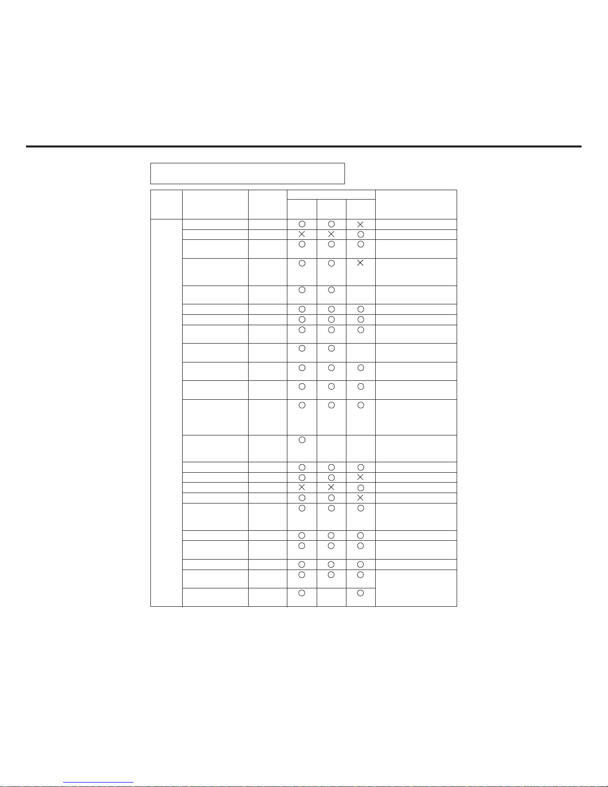
1. 5 Commonality of accessories ................................................................ 1-8
1. 6 Operation ............................................................................................. 1-11
1. 7 Component Location............................................................................ 1-13
1. Outer view........................................................................................ 1-13
2. Inner view......................................................................................... 1-14
3. Fan/Motor Location (FP-D250/D350/D350H) .................................. 1-16
4. Fan/Motor Location (FP-D450/D600)............................................... 1-17
5. Sensor Location............................................................................... 1-18
6. Solenoid/Clutch/Discharge lamp Location ....................................... 1-19
7. PCB Location (FP-D250/D350/D350H) ........................................... 1-20
8. PCB Location (FP-D450/D600)........................................................ 1-20
9. Hard Disk Drive/Zip Drive Location.................................................. 1-21
1. 8 Copy Process....................................................................................... 1-22
1. 9 Precautions with Consumables ........................................................... 1-23
1. 10
Digital Image Control Qualitative Reasoning Based Adaptive Controller..
1-25
II. Sub Assemblies
2. 1 Main Drive............................................................................................ 2-1
2. 2 Operation ............................................................................................. 2-2
1. Sheet bypass paper feed................................................................. 2-2
2. Paper feed unit................................................................................. 2-5
3. Developer unit.................................................................................. 2-8
4. Toner hopper unit............................................................................. 2-16
5. Paper transport unit and separation unit.......................................... 2-20
6. Fuser unit......................................................................................... 2-21
7. Optics unit........................................................................................ 2-26
8. Automatic duplex unit (ADU)............................................................ 2-33
Back to Model ListFP-D250/D350/D450/D600

III. Preventive Maintenance
3. 1
Precautions for Preventive Maintenance Service .................................
3-1
3. 2 Precautions for handling ...................................................................... 3-3
3. 3 Maintenance chart ............................................................................... 3-5
1. Replacement (For FP-D250)............................................................ 3-5
2. Replacement (For FP-D350/D350H) ............................................... 3-7
3. Replacement (For FP-D450/D600).................................................. 3-9
3. 4 Cleaning Method.................................................................................. 3-11
3. 5 Disassembly......................................................................................... 3-14
1. Multi-feed bypass............................................................................. 3-15
2. Paper feed unit................................................................................. 3-18
3. Developer unit.................................................................................. 3-21
4. Fuser unit......................................................................................... 3-25
5. Optics unit ........................................................................................ 3-30
6. Automatic duplex unit (ADU) (Option).............................................. 3-33
7. Main body ........................................................................................ 3-36
3. 6 Removal of back up battery ................................................................. 3-40
3. 7 Adjustment ........................................................................................... 3-41
1. Exposure Standard Adjustment ....................................................... 3-42
2. Copy density Sensor contamination adjustment.............................. 3-43
3. Skew / Side to side Adjustments (Printer Section) .......................... 3-44
4. Skew / Registration Adjustments (Scanner Section) ....................... 3-46
5. Lead edge / Trail edge void adjustment (Printer Section)................ 3-47
6. Laser power (PWM circuit)............................................................... 3-48
IV. PCB Connector and Signal Information
4. 1 Glossary of electrical abbreviations ..................................................... 4-1
4. 2 Main CPU PCB (FP-D250/D350 Series) ............................................. 4-7
4. 3 System Control PCB (FP-D250/D350 Series) ..................................... 4-53
4. 4 Control Panel PCB (FP-D250/D350 Series) ........................................ 4-71
1. Control Panel CPU PCB (FP-D250/D350 Series)............................ 4-71
2. Control Panel PCB A (FP-D250/D350 Series)................................. 4-77
3. Control Panel PCB B (FP-D250/D350 Series)................................. 4-81
4. Control Panel PCB C (FP-D250/D350 Series)................................. 4-82
5. Control Panel PCB D (FP-D250/D350 Series)................................. 4-84
4. 5 CCD PCB (FP-D250/D350 Series) ...................................................... 4-85
4. 6 SO DIMM PCB (FP-D250/D350 Series) .............................................. 4-88
4. 7 16 M Flash DIMM PCB (FP-D250/D350 Series) ................................. 4-94

Introduction
Sub
Assemblies
Preventive
Maintenance
PCB Connector and
Signal Information
Troubleshooting
Unpacking/
Installation
Glossary
of Terms
4. 8 LSU Image Data Control PCB (FP-D250/D350 Series)....................... 4-100
4. 9
Automatic Duplex Unit (ADU) Driver PCB (Option) (FP-D250/D350 Series)...
4-104
4. 10 Low Voltage Power Supply PCB (FP-D250/D350 Series)................... 4-109
4. 11 High Voltage Power supply PCB (FP-D250/D350 Series)................... 4-117
4. 12 AC Drive PCB (FP-D250/D350 Series) ............................................... 4-118
4. 13 Printer controller PCB (Option) (FP-D250/D350 Series) ..................... 4-120
4. 14 Network card (Option) (FP-D250/D350 Series) ................................... 4-140
4. 15 Hard Disk Drive for Filing/Back-up (FP-D250/D350 Series) ................ 4-148
4. 16 Zip Drive (FP-D250/D350 Series)........................................................ 4-152
4. 17 Main CPU PCB (FP-D450/D600 Series) ............................................. 4-156
4. 18 System Control PCB (FP-D450/D600 Series) ..................................... 4-187
4. 19 Control Panel PCB (FP-D450/D600 Series) ........................................ 4-205
1. Control Panel CPU PCB (FP-D450/D600 Series)............................ 4-205
2. Control Panel PCB A (FP-D450/D600 Series)................................. 4-211
3. Control Panel PCB B (FP-D450/D600 Series)................................. 4-215
4. Control Panel PCB C (FP-D450/D600 Series)................................. 4-216
5. Control Panel PCB D (FP-D450/D600 Series)................................. 4-218
4. 20 CCD PCB (FP-D450/D600 Series) ...................................................... 4-219
4. 21 SO DIMM PCB (FP-D450/D600 Series) .............................................. 4-222
4. 22 16 M Flash DIMM PCB (FP-D450/D600 Series) ................................. 4-228
4. 23 LSU Image Data Control PCB (FP-D450/D600 Series)....................... 4-234
4. 24
Automatic Duplex Unit (ADU) Driver PCB (Option) (FP-D450/D600 Series)...
4-238
4. 25 Low Voltage Power Supply PCB (FP-D450/D600 Series)................... 4-243
4. 26 High Voltage Power supply PCB (FP-D450/D600 Series)................... 4-251
4. 27 AC Drive PCB (FP-D450/D600 Series) ............................................... 4-252
4. 28 Printer controller PCB (Option) (FP-D450/D600 Series) ..................... 4-254
4. 29 Network card (Option) (FP-D450/D600 Series) ................................... 4-274
4. 30 Hard Disk Drive for Filing/Back-up (FP-D450/D600 Series) ................ 4-282
4. 31 Zip Drive (FP-D450/D600 Series)........................................................ 4-286
4. 32 Image processing PCB (FP-D450/D600 Series) ................................. 4-290

V. Troubleshooting
5. 1 Service Mode....................................................................................... 5-1
1. Service mode functions.................................................................... 5-1
2. Service mode procedure.................................................................. 5-3
3. F4 mode input/output check............................................................. 5-3
4. F5 mode Copier function programming ........................................... 5-17
5. F6 mode Adjustment and programming .......................................... 5-24
6. F7 mode electronic counter ............................................................. 5-32
7. F8 mode copier operation adjustment ............................................. 5-37
8. F9 mode system administration ....................................................... 5-39
5. 2 Self-diagnostics / Machine Malfunctions.............................................. 5-40
1. User error......................................................................................... 5-40
2. Paper Jam........................................................................................ 5-45
3. Machine error................................................................................... 5-50
5. 3 User Preset Mode................................................................................ 5-73
1. Operation procedure........................................................................ 5-73
2. Example: Paper size setting ............................................................ 5-73
5. 4 Program Update .................................................................................. 5-87
1. Update procedure of the printer controller SIMM............................ 5-87
VI. Unpacking/Installation
6. 1 Precautions on Set Up......................................................................... 6-1
6. 2 Unpacking............................................................................................ 6-2
6. 3 Installation Procedure .......................................................................... 6-3
6. 4 Adjustment ........................................................................................... 6-10
6. 5 Printer Unit/DD Filing Unit Mounting kit (FA-PK30) ............................. 6-13
6. 6 Printer Unit (FA-PC350) / Multi PDL Controller (FA-MC350)............... 6-19
6. 7 Network Adapter Card for Ethernet (FA-NE35) ................................... 6-22
6. 8 Hard Disk Driver for Printer (FA-HD01) ............................................... 6-25
6. 9 DD filing unit (FA-WA01/WA02)........................................................... 6-27
6. 10 Hard Disk Driver for back up (FA-HD02) ............................................. 6-35
6. 11 Hard Disk Driver for Image memory (FA-HD03/HD04)........................ 6-37
VIl. Glossary of Terms
Network, Printing, Copying and imaging Terms .................................. 7-1
TORANO-MAKI (FP-D250/D350 Series)
TORANO-MAKI (FP-D450/D600 Series)
Electrical schematic diaglam

WARNING
This service information is designed for experienced repair technicians only and
is not designed for use by the general public.
It does not contain warnings or cautions to advise non-technical individuals of
potential dangers in attempting to service a product.
Products powered by electricity should be serviced or repaired only by experienced
professional technicians. Any attempt to service or repair the product or products
dealt with in this service information by anyone else could result serious injury or
death.
For U.S.A
This equipment has been tested and found to comply with the limits for a Class A
digital device, pursuant to part 15 of the FCC Rules. These limits are designed to
provide reasonable protection against harmful interference when the equipment
is operated in a commercial environment. This equipment generates, uses, and
can radiate radio frequency energy and, if not installed and used in accordance
with the instruction manual, may cause harmful interference to radio
communications. Operation of this equipment on a residential area is likely to
cause harmful interference in which case the user will be required to correct the
interference at his/her own expense.
Any unauthorized changes or modifications to this equipment would void the users
authority to operate this device.
For U.S.A
This manual was developed and is supplied to authorized servicing dealers by
Panasonic Document Imaging Co. for the sole purpose of providing information
necessary for the equipment’s proper support. It is intended that this information
be confidential and may not reproduced without prior written consent from
Panasonic Document imaging Co. Panasonic Document imaging Co. reserves
the right to change any information enclosed herein without prior notification.
This manual was developed and is supplied to authorized servicing dealers by
Panasonic Co. for the sole purpose of providing information necessary for the
equipment’s proper support. It is intended that this information be confidential
and may not be reproduced without prior written consent from Panasonic Co.
Panasonic Co. reserves the right to change any information enclosed herein without
prior notification.
For U.S.A
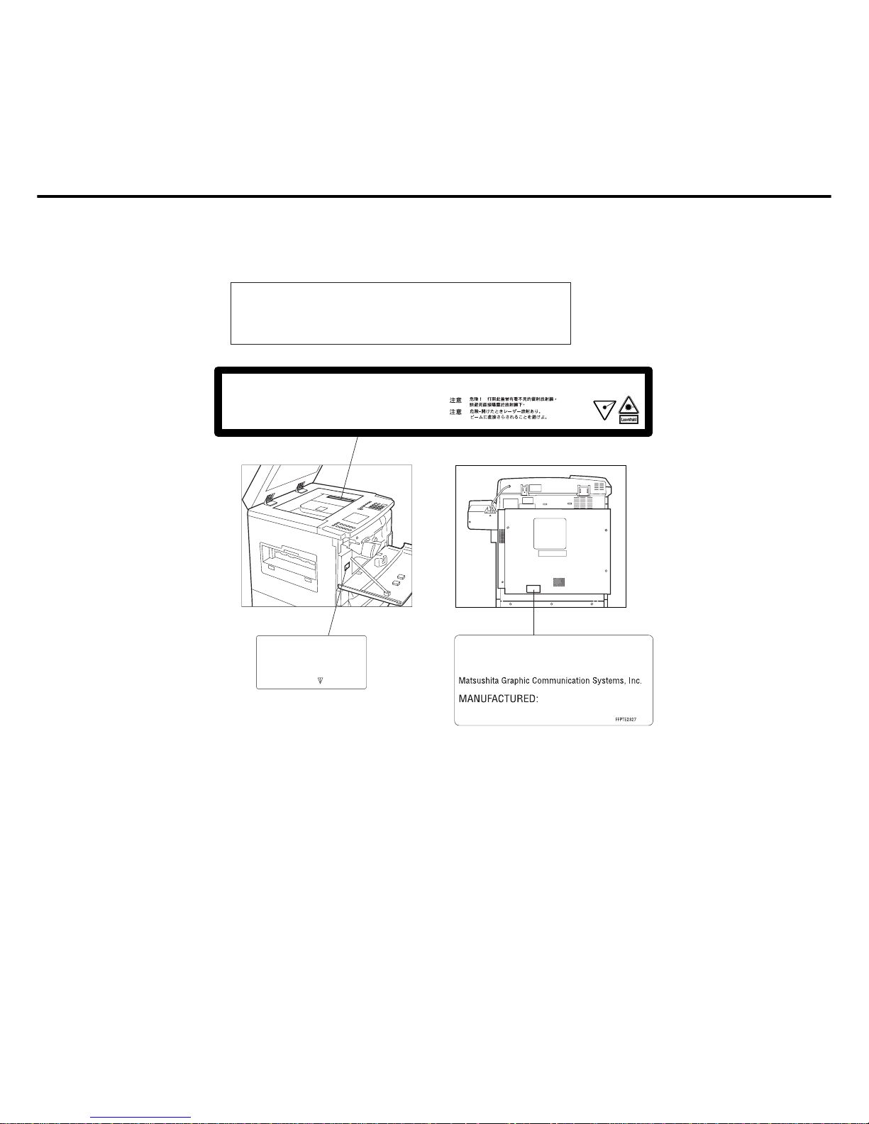
For your safety
Caution
This product utilizes a laser.
Use of controls or adjustments or performance of procedures other than
those specified herein may result in hazardous radiation exposure.
DANGER
CAUTION
ATTENTION
VORSICHT
PRECAUTION
Invisible laser radiation when open.
Avoid direct exposure to beam.
Invisible laser radiation when open.
Avoid direct exposure to beam.
Rayonnement laser invisible si ouvert.
Dangereux de regarder a l'interieur.
Unsichtbare laserstrahlen wenn geöffnet.
Nicht hinensehen.
Peligro-Cuando la cubierta esté abierta se
podrá escapar radiación de rayo láser.
Evite la exposición directa al rayo láser.
FFPTE
DANGER-Invisible laser
radiation when open and
interlock defeated.
AVOID DIRECT EXPOSURE
TO BEAM.
Product complies with DHHS Rules 21
CFR Subchapter J in effect of date
of manufacture.
Utsunomiya, Tochigi, Japan
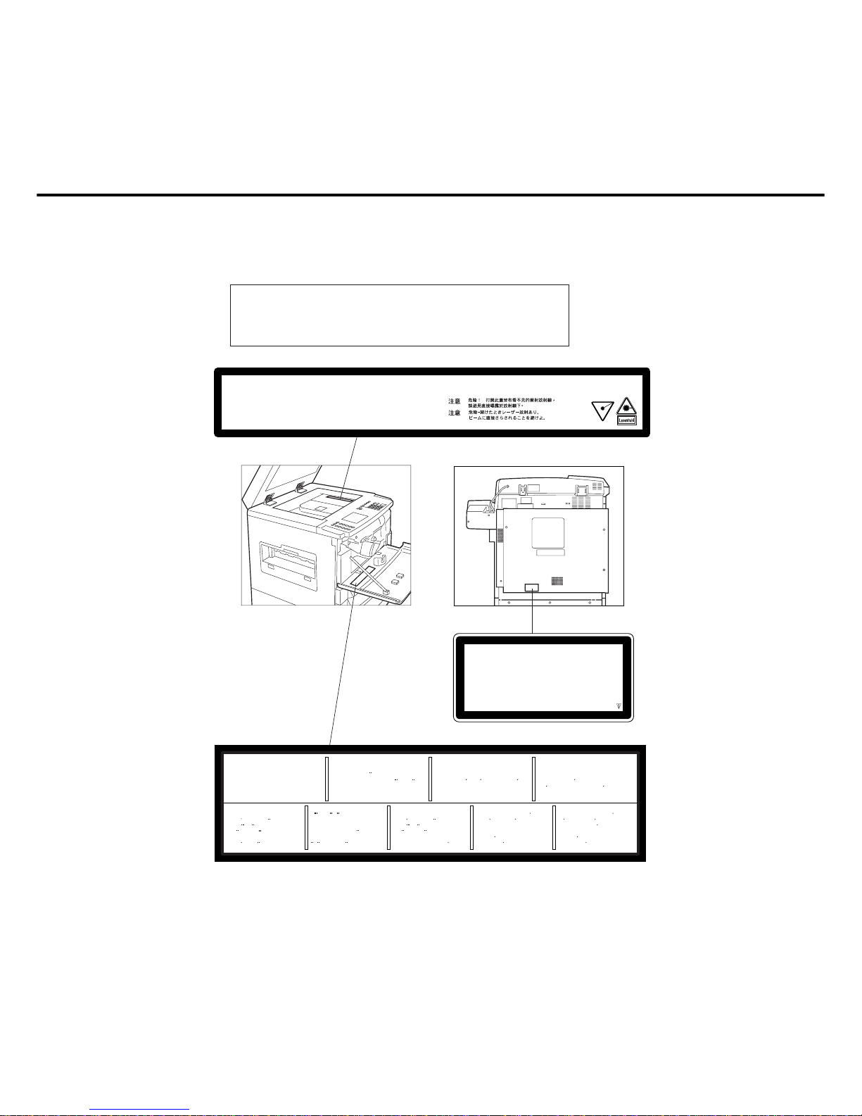
For your safety
Caution
This product utilizes a laser.
Use of controls or adjustments or performance of procedures other than
those specified herein may result in hazardous radiation exposure.
DANGER
CAUTION
ATTENTION
VORSICHT
PRECAUTION
Invisible laser radiation when open.
Avoid direct exposure to beam.
Invisible laser radiation when open.
Avoid direct exposure to beam.
Rayonnement laser invisible si ouvert.
Dangereux de regarder a l'interieur.
Unsichtbare laserstrahlen wenn geöffnet.
Nicht hinensehen.
Peligro-Cuando la cubierta esté abierta se
podrá escapar radiación de rayo láser.
Evite la exposición directa al rayo láser.
CAUTION
:
Invisible laser radiation when open
and interlocks defeated.
AVOID EXPOSURE TO BEAM.
VARO!
:
NAKYMATON AVATTAESSA
JA SUOJALUKITUS
OHITETTAESSA OLET
ALTTIINA LASERSATEIL
YLLE.
ALA KATSO SATEESEN.
VORSICHT
:
Unsichtbare Laserstrahlung, wenn
Abdeckung geoffnet und
Sicherheitsverriegelung uberbruckt.
NICHT DEM STRAHL
AUSSETZEN.
ATTENTION
:
Rayonnement laser invisible
dangereux en cas d'ouverture et
lorsque la securite est neutralisee.
EXPOSITION DANGEREUSE AU
FAISCEAU.
PELIGRO
:
Cuando se abre y se invalida el
bloqueo, se producen radiaciones
invisibles de laser.
EVITESE LA EXPOSICION
DIRECTA A TALES RAYOS.
VARNING
:
OSYNLIG LASERSTRALNING NAR DENNA
DEL AR OPPNAD OCH
SPARRAR AR
URKOPPLADE.
STRALEN AR FARLIG.
VARNING
:
OSYNLIG LASERSTRALNING NAR DENNA
DEL AR OPPNAD OCH
SPARREN AR
URKOPPLAD.
BETRAKTA EJ STRALEN.
ADVARSEL
:
USYNLIG LASERSTRALING
VED ABNING NAR
SIKKERHEDSAFBRYDERE ER
UDE AF FUNKTION.
UNDGA UDSÆTTELSE
FOR STRALING.
ADVARSEL
:
USYNLIG LASERSTRALING
NAR DEKSEL APNES OG
SIKKERHEDSLAS BRYTES.
UNNGA EKSPONERING
FOR STRALEN.
FFPTE2412
LASER KLASSE 1
LASER CLASSE 1
RANGO LASER 1
CLASS 1 LASER P
R
ODUCT
(
TO IEC 825
)
FFPTE1538
For Sweden, and Denmark
SPECIALSÄKRING: ENDAST AV APPARATFABRINKANTEN LEVERERAD
SÄKRING FåR ANVÄNDAS.
VARNING!
Explosionsfara vid felaktigt batteribyte.
Använd samma batterityp eller ekvivalent typ som rekommenderas av
apparattillverkaren. Kassera använt batteri enligt fabrikantens instruktion.
ADVARSEL!
Lithiumbatteri—Eksplosionsfare ved
fejlagtig håndtering.
Udskiftning må kun ske med batteri
af samme fabrikat og type.
Lever det brugte batteri tilbage til
leverrandoren.
CAUTION!
Danger of explosion if battery is incorrectly replaced. Replace only with the
same or equivalent recommended by the manufacturer. Dispose of used
batteries according to the manufacturer’s instructions.
For Holland
Batterij niet
weggooien, maar
inleveren als KCA.
NL
Caution: Danger of explosion if battery is incorrectly replaced.
Replace only with the same or equivalent type recommended by the manufacturer.
Dispose of used batteries according to the manufacturer’s instructions.

For U.K.
FOR YOUR SAFETY PLEASE READ THE FOLLOWING TEXT CAREFULLY.
This appliance is supplied with a moulded three pin mains plug for your safety and
convenience. A 13 amp fuse is fitted in this plug.
Should the fuse need to be replaced please ensure that the replacement fuse has a rating
of 13 amps and that it is approved by ASTA or BSI to BS1362.
Check for the ASTA mark or the BSI mark on the body of the fuse.
If the plug contains a removable fuse cover you must ensure that it is refitted when the fuse
is replaced.
If you lose the fuse cover the plug must not be used until a replacement cover is obtained.
A replacement fuse cover can be purchased from your local Panasonic Dealer.
IF THE FITTED MOULDED PLUG IS UNSUITABLE FOR THE SOCKET OUTLET IN YOUR
OFFICE THEN THE FUSE SHOULD BE REMOVED AND THE PLUG CUT OFF AND
DISPOSED OF SAFELY.
THERE IS A DANGER OF SEVERE ELECTRICAL SHOCK IF THE CUT OFF PLUG IS
INSERTED INTO ANY 13 AMP SOCKET.
If a new plug is to be fitted please observe the wiring code as shown below.
If in any doubt please consult a qualified electrician.
WARNING: THIS APPLIANCE MUST BE EARTHED.
IMPORTANT: The wires in this mains lead are coloured in accordance with the following
code:
Green and Yellow :Earth
Blue :Neutral
Brown :Live
As the colours of the wires in the main lead of this appliance may not correspond with the
coloured markings identifying the terminals in your plug, proceed as follows:
The wire which is coloured GREEN-AND-YELLOW must be connected to the terminal in the
plug which is marked by letter E or by the safety EARTH symbol “ ” or coloured GREEN or
GREEN-AND-YELLOW.
The wire which is coloured BLUE must be connected to the terminal in the plug which is
marked with the letter N or coloured BLACK.
The wire which is coloured BROWN must be connected to the terminal in the plug which is
marked with the letter L or coloured RED.
How to replace the fuse.
Open the fuse compartment with a screwdriver and replace the fuse.
Fuse
Fuse

Introduction
1-1
Section I Introduction
1. 1 Specifications
<Basic Specifications>
Type Desk Top
Platen Fixed
Copy / Print process Laser / Electrostatic photographic method
Development process Two component magnetic brush
Image control process Digital QUANTUM (QUARC) control
Photoreceptor Organic Photo Conductor (OPC)
Fusing system Heat and Pressure
Maximum original size Ledger (11" × 17") / A3 (297 × 420mm)
Paper feed Front loading universal paper cassette
Multi-feed bypass tray
Paper capacity Cassette :
550 sheet × 2 (FP-D250/D350 Series)
:
550 sheet × 1 (FP-D450/D600)
Bypass : 50 sheets
Copy size Ledger / A3 – Invoice / A5
Paper exit tray capacity 250 sheets
Ambient conditions Temperature : 50–86°F / 10–30 °C
Relative humidity : 30–80%
Noise level Stand-by : 32 dB
Operation : 49 dB (FP-D250/D350 series)
: 54 dB (FP-D450/D600)
Warm up time Approx. 75 sec. (FP-D250/D350 series)
Approx. 180 sec. (FP-D450/D600)
Power consumption Less than 1.4 kW (FP-D250/D350 series)
Less than 1.45 kW (FP-D450/D600)
Power source AC 120V 60Hz (North America)
AC220 - 240V 50Hz (Europe / Others)
Dimensions (W)(D)(H) 23.9" × 30.3" × 24.6" / 606 × 770 × 624 mm
Weight 167 lbs / 76kg (FP-D250/D350)
180 lbs / 82kg (FP-D350H)
185 lbs / 84kg (FP-D450/D600)
Paper weight Cassette : 16–24 lbs ( 60–90g/m2)
Bypass : 15–34 lbs (55–130g/m
2
)

1-2
Special paper OHP, Label paper, Tracing paper
(Through multi-feed bypass)
<Copier Specifications>
Resolution 600 dpi (FP-D250/D350 series)
400 dpi (FP-D450/D600)
Gradation 256 steps (Photo Mode)
2 steps (Text/Photo Mode)
First copy time 3.9 sec. (Letter/A4 size, without Auto mode)
(FA-D250/D350 series)
3.2 sec. (Letter/A4 size, without Auto mode)
(FA-D450)
2.9 sec. (Letter/A4 size, without Auto mode)
(FA-D600)
5.1 sec. (Letter/A4 size, with Auto mode)
(FA-D250/D350 series)
4.0 sec. (Letter/A4 size, with Auto mode) (FA-D450)
3.5 sec. (Letter/A4 size, with Auto mode) (FA-D600)
Copy ratio Enlargement (fixed) : (North America)
2.00, 1.55, 1.29, 1.21
: (Europe / others)
2.00, 1.73, 1.41, 1.22, 1.15
Reduction (fixed) : (North America)
0.79, 0.77, 0.65, 0.61, 0.50
(Europe / others)
0.87, 0.82, 0.71, 0.58, 0.50
Zoom : 25%-400% (1% step)
Copy speed D250
D350 series
D450 D600
Ledger / A3 : 18 CPM 20 CPM 29 CPM 34 CPM
Legal / B4,FLS : 20 CPM 23 CPM 33 CPM 39 CPM
Letter-R / A4R : 23 CPM 28 CPM 38 CPM 49 CPM
Letter / A4 : 28 CPM 35 CPM 45 CPM 60 CPM
Invoice / A5 : 28 CPM 35 CPM 45 CPM 60 CPM
Continuous copying 1-999 reset to 1

Introduction
1-3
<Printer Specifications>
Resolution Max. 600 dpi (True) / 1200 dpi (Smoothing)
Print speed
28 ppm (pages per minute) Letter / A4 (FP-D250)
35 ppm (pages per minute) Letter / A4 (FP-D350 series)
45 ppm (pages per minute) Letter / A4 (FP-D450)
50 ppm (pages per minute) Letter / A4 (FP-D600)
Print size Ledger / A3 - Invoice / A5
Memory capacity 8 MB / Standard (expandable up to 40MB)
Spooling Memory Hard Disk (120, 256 or 512 MB/option)
Printer Description Language
PCL 5e emulation, Postscript level 2 emulation (Option)
Interface Bi-directional parallel (IEEE1284), Network I/F (option)
Font In accordance with emulation type
Operating system Windows 3.1 (North America), Windows 95,
Windows 98, Windows NT 4.0, MacOS 7.5.2/8.X
(MacOS7.5.2 support available with Postscript option)
<Network Specifications>
Board type Option board connected to printer unit
Memory capacity 1 MB
Connecting type Ethernet (100 BaseTX, 10 BaseT)
Communications protocol Ethernet (TCP/IP, IPX/SPX, EtherTalk)
Operating system Windows 3.1/95, Windows NT4.0,
Mac OS, NetWare 3.1x/4,X
<Filing Specifications>
Resolution 600 dpi (400dpi : D450/D600), 300 dpi and 200 dpi
Paper size Ledger/A3 - Invoice/A5
Storage media Hard disk
Storage capacity 2 GB (For filing storage 1.5 GB, for system files/copy
image storage 0.3 GB)
External storage device Zip drive (100 MB)
File format TIFF
Compression type JBIG (600 dpi)
MMR (200/300 dpi)
* Specifications are subject to change without notice.

1-4
1. 2 Features
<General Features>
1. Use of new digital technology
1) Optimum image quality is maintained for a long period in varying environmental conditions with the use of Digital QUANTUM (QUARC) technology.
Digital QUANTUM (QUARC): Digital Qualitative Reasoning Based Adaptive
Controller.
2) Unique functions such as digital skyshot, page number print and much more,
makes useful and interesting image effects.
2. Quick speed operation
1) With the use of speed control clutch in the paper feed unit, a 2.9 sec. first
copy speed which is the fastest in this range be achieved. (FP-D600)
2) Original throughput speed from the i-ADF/ADF (optional) is the same as machine speed. (100%throughput) (Except for FP-D600)
3. User friendly operation
1) Bi-directional communication touch panel display enables easy operation by
simply touching the icon on the wide screen.
2) Paper level sensor in the cassette indicates a low paper condition.
This function prevents no paper condition during the operation.
4. Various optional accessories are available for functional expansion.
1) Operational efficiency can be further increased by attaching ADF, Finisher,
LCC and system console.
<Printer Features>
1. High resolution printing of 600 x 600dpi (1200dpi: Smoothing)
1) Enables the printing of documents, photographs, and fine line drawings from
the PC.
By changing the resolution to 300 x 300dpi, printing time can be minimized.
2. Ledger/A3 size printing
1) Enables the printing of Invoice/A5 to Ledger/A3 size.
Useful for output such as drawings.

Introduction
1-5
3. Printing speed of 50 prints per minute (Letter/A4)(FP-D600)
1) Enables high volume document printing in a short time.
4. PCL5e format printer
1) PCL5e is the Page Description Language of the Hewlett-Packard Company.
5. Windows® 95/Windows® 3.1/Windows NT®4.0
1) The made document can be printed out using application software designed
for Windows
®
95, Windows® 3.1 (North America) & Windows NT® 4.0 operat-
ing systems.
6. Fonts
1) The printer comes with 45 scaleable fonts.
2) You can scale TrueType fonts within the printer. You also receive matching
TrueType screen fonts for true WYSIWYG, short for "What you see is what
you get". These internal fonts are part of the PCL language.
7. Options
1) Expansion memory (16 MB)
Faster print speed can be expected by speed of rasterrinsing process.
When the image processing memory of the copier is 8 MB (FP-D250 : All, FPD350 : except North America) : If the machine error often occurs when the high
density of information document (such as gray color A3 size print) is being
printed, even though printer memory is additionally installed, install the additional image memory of the printer (8MB/16MB)
2) Hard disk
Enables the install action of additional fonts which are not included in the unit.
3) Network unit
Use as local network printer in the office.
Network format is Ethernet.
When the Ethernet is installed, operation status of the printer and connection
of the optional accessories can be checked form the PC.

1-6
1. 3 New functions
1. Digital Skyshot
Black edges are removed automatically, however if the original is not square to
the original guide the copy may have some edges printed in black.
2. Page Number print.
The page number can be automatically printed on each page.
3. Multi Original Image Rotation
If the paper direction in the cassette is different from the direction of the original,
the image is automatically rotated 90 degrees so that the proper copy is obtained.
4. N in 1 copy mode
From two (or four) 1-sided originals side by side to 1-sided copies can be made.
5. Wide Zoom Ratio (25%-400%)
Copies can be made from 25% to 400% of the original document size at 1%
increments.
6. X-Y Zoom
Independent height-width zoom copies can be made.
Introduction
1-7
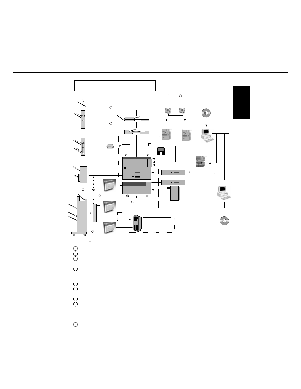
Platen cover
Mounting Kit
FA-GK35
Platen Cover
FA-UC20
Automatic
Document
Feeder
FA-A355
Inverting Automatic
Document Feeder
FA-A888
Mounting Kit
FA-PK30
Hard Disk Drive
for Printer
FA-HD01
System Stand
FA-DS725
FA-DS825
Inverting
Shift Tray
FA-TR350
2 Bin Inverting
Shift Tray
FA-TR355
Hard Disk Drive
for Mirroring
FA-HD02
Hard Disk Drive
for Image memory
FA-HD03 (For FP-D250/D350/D350H)
FA-HD04 (For FP-D450/D600)
Inverting
Unit
FA-RU350
5
3 Bin Finisher
FA-F350/F355
4
3
1
2
Exit Tray
FA-X350
9
2 Bin Finisher
FA-F320
8
Exit Guide Unit
FA-FK35
6
Mounting kit
FA-PK30
DD Filing Unit
H/D (2GB)
Personal Card x 10 pcs
Card Reader
Zip Drive
Battery
Personal Card
FA-KP01
Card Reader
Automatic Duplex unit
FA-MADM65
550 Sheet Paper Drawer
FA-MA0555
3000 Sheet Cassette
FA-MA301
Paper drawer Kit
FA-DK10
Printermemory
(32MB)
FA-PM32
Printer
Memory
(16MB)
FA-PM16
PCL5e Printer Unit
FA-PC350
PC
Server
Network Adapter Card
Multi Page Description
Language Controller
(PCL5e / PS-II) FA-MC350
7 7
DD Browser
Software
FA-WB10
DD Server Software
FA-WS10
ZIP Drive
EtherNet : FA-NE35
FA-WA01 (For FP-D250/D350/D350H)
FA-WA02 (For FP-D450/D600)
1. 4 System Configuration
1 • Original face down
2 • Optional platen cover mounting kit (FA-GK35) is required to install platen cover
3 • 550 module can be installed all 3 slots
• Drawer kit (FA-DK10) is required for lower slot
4 • Staple (50 sheets)
• Shift
• For FP-D450/D600 (FA-F355)
5 • In case face down exit is required with FA-F350/355
6 • Optional exit guide unit (FA-FK35) is required to install finisher
[Not required for FA-F350/355 when FA-RU350 is installed]
7 • Except for North America and Europe
8 • Hole punch
• Staple (30 sheets, bottom bin only)
• Shift (bottom bin only)
• For FP-D250/D350
9 • For North America
1-8
Description
System Stand
System Stand
550 Sheet Paper
Drawer
Paper Drawer Kit for
System Stand
Automatic Duplex
Unit
3000 Sheet Cassette
Platen Cover
Platen Cover
Mounting Kit
Automatic
Document Feeder
Inverting Automatic
Document Feeder
Check Guide Kit for
ADF (FA-A888)
Platen Glass Kit
Platen Glass Kit
Exit Tray
3 Bin Finisher
3 Bin Finisher
2 Bin Finisher
Exit Guide Unit
Inverting unit
2 Bin Inverting Shift
Tray
Inverting Shift Tray
Image Processing
Memory (8 MB)
Image Processing
Memory (16 MB)
Model number
FA-DS725
FA-DS825
FA-MA0555
FA-DK10
FA-MADM65
FA-MA301
FA-UC20
FA-GK35
FA-A355
FA-A888
FFPTL0277
FFPTL0323
FFPTL0324
FA-X350
FA-F350
FA-F355
FA-F320
FA-FK35
FA-RU350
FA-TR355
FA-TR350
FA-DM08
FA-DM16
FP-D250
D350
Remarks
Kit required for FA-MA0555
installation in bottom slot
of FA-DS725
Available through parts
route
This kit is required when
installing FA-A888 (North
America)
Available through parts route
This kit is required when
installing FA-A888 (Europe)
Available through parts route
For North America
Required for : FA-F320
and FA-F350/F355 when
FA-RU350 is not installed.
For FA-F350/F355
Expansion memory limited
to 8 MB or 16 MB
Except for North America
and Europe
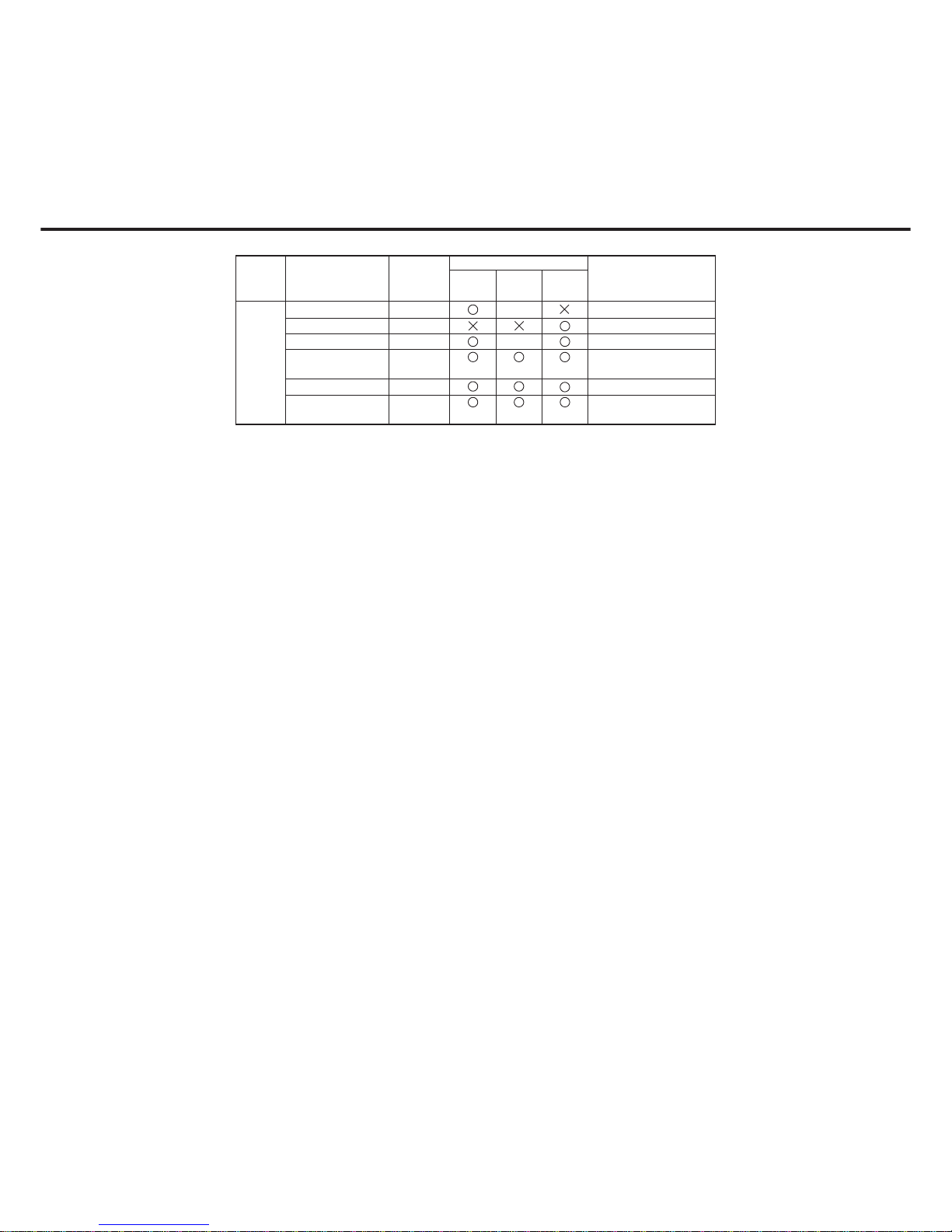
1. 5 Commonality of accessories
Main
Accessories
Model Number
FP-D350H FP-D450
D600
Standard
Standard
(D350:
Standard)
Standard
Standard
Introduction
1-9
Description
Operators Guide
Pocket
Dehumidifier Heater
for Optics
Dehumidifier Heater
for Drum
Key Counter
Harness Kit
Dehumidifier Heater
for System Stand
Dehumidifier Heater
for System Stand
Dehumidifier Heater
for LCC
Dehumidifier Heater
for LCC
Blind Cover kit
Printer Unit / DD
Filing Unit Mounting
Kit
Hard Disk Drive for
Image Memory
Printer Unit
Multi Page Description
LanguageController
Hard Disk Drive for
Printer
Printer Memory
(16MB)
Printer Memory
(32MB)
Network Unit for
Ethernet
Toner
Toner
Developer
Developer
Drum
Waste Toner Bottle
Staple
Staple
Main
Accessories
Printer
Accessories
Network
Accessories
Consumables
Remarks
Available through parts
route
Available through parts
route
Available through parts
route
Available through parts
route
For North America
Available through parts route
For Europe
Available through parts route
For North America
Available through parts route
For Europe
Available through parts route
Available through parts route
This kit is required when
installing printer unit
8MB
2GB
Expansion memory limited
to 16 MB or 32 MB
Except for North America
and Europe
10/100 base TX
20,000 copies (Letter/A4,
6% density)
24,000 copies (Letter/A4,
6% density)
120,000 copies (FP-D350)
80,000 copies (FP-D250)
120,000 copies
120,000 copies (FP-D350/D450/D600)
80,000 copies (FP-D250)
For use in FA-F350/F355
(5,000 staples)
For use in FA-F320
(3,000 staples)
Model Number
FP-D450
D600
FP-D350HFP-D250
D350
Standard
Standard
Model number
FFPXJ19908
FFPTL0304
FFPTL0270
FFPTL0308
FFPTL0273
FFPTL0274
FFPTL0275
FFPTL0276
FFPTL0326
FA-PK30
FA-HD03
FA-HD04
FA-PC350
FA-MC350
FA-HD01
FA-PM16
FA-PM32
FA-NE35
FQ-TL20
FQ-TL24
FQ-ZL20
FQ-ZL30
FQ-HL20
FQ-BA10
FQ-SS75
FQ-SS32
1-10
Description
DD Filing Unit
DD Filing Unit
Personal Card
DD Browser
Software
DD Server Software
Hard Disk Drive for
Back-up
DD filing
Accessories
Remarks
For FA-WA01/WA02
Model Number
FP-D450
D600
FP-D350HFP-D250
D350
Model number
FA-WA01
FA-WA02
FA-KP01
FA-WB10
FA-WS10
FA-HD02
Standard
Standard
Introduction
1-11
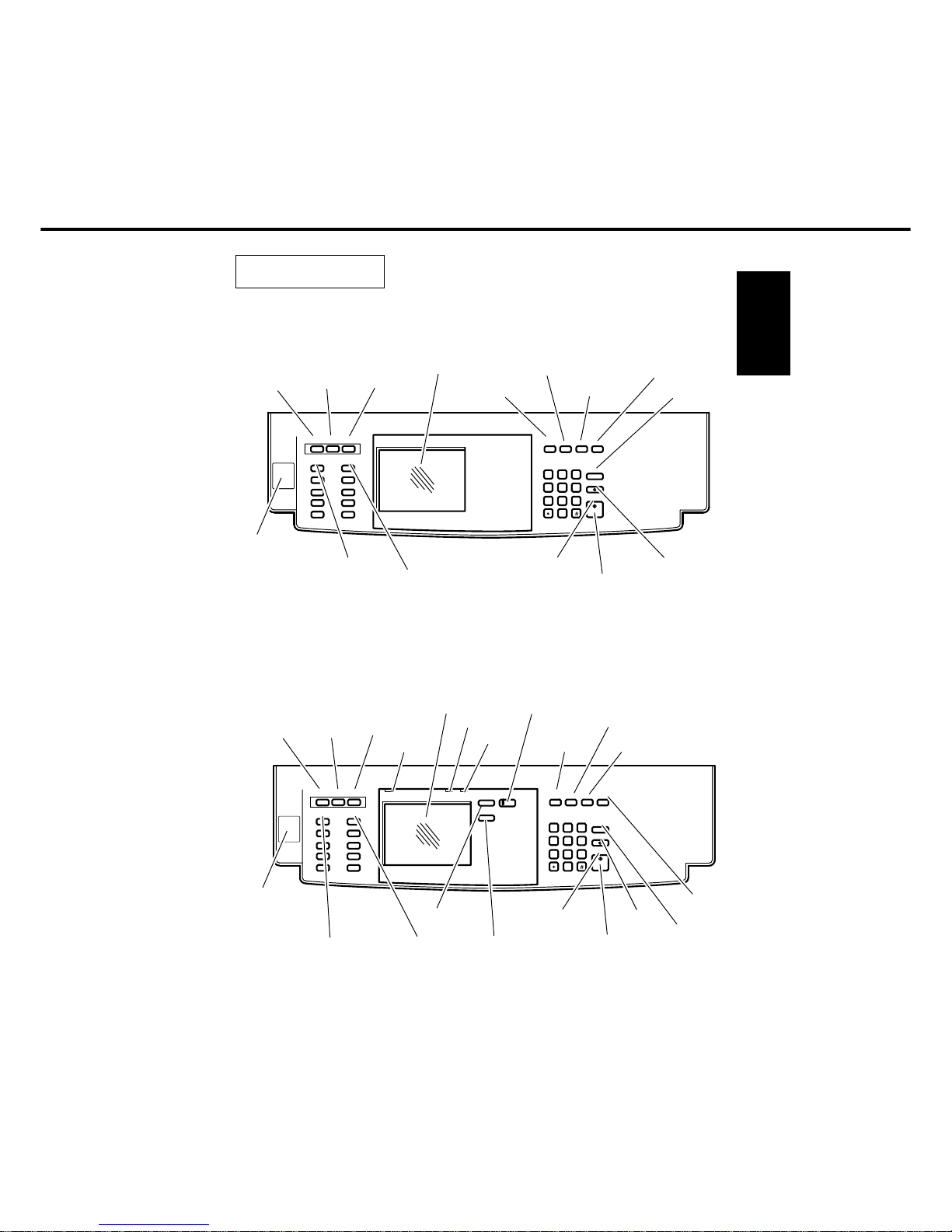
1. 6 Operation
FP-D250 / D350 / D450 / D600 (Printer, Filing, option)
USER
PRESET
MULTI-SIZE
FEED
SORT/
FINISH
INTERRUPT
MANUAL
ENERGY
SAVER
ADD PAPER
ONLINE
DATA
DOCUMENT
SAVE
TOUCH
PANEL
DISPLAY
RESET
CLEAR
STOP
START
ADVANCED
FUNCTIONS
COPY
ORIGINAL SIZE
OPERATION
SWITCH
(D450/D600)
COPY SIZE
Ready Indicator
Ready:GreenLED
Not ready:RedLED
Copy Reservation:FIashing
FP-D250 / D350 / D450 / D600
USER
PRESET
MULTI-SIZE
FEED
SORT/
FINISH
INTERRUPT
MANUAL
ENERGY
SAVER
RESET
CLEAR
STOP
START
TOUCH
PANEL
DISPLAY
ORIGINAL SIZE
COPY SIZE
Ready Indicator
Ready:GreenLED
Not ready:RedLED
Copy Reservation:FIashing
OPERATION
SWITCH
(D450/D600)
USER
PRESET
ORIGNAL SIZE COPY SIZE
MULTI-SIZE
FEED
SORT/
FINISH
ADVANCED
FUNCTIONS
ADDPAPER
ONLINE DATA
DOCUMENT
SAVE
INTERRUPT
MANUAL
ENERGY
SAVER
RESET
CLEAR
STOP
START
c
9
1
2
65
4
7
8
0
3
CLEAR
STOP
START
c
9
1
2
65
4
7
8
0
3
USER
PRESET
ORIGNAL SIZE COPY SIZE
MULTI-SIZE
FEED
SORT/
FINISH
INTERRUPTMANUAL
ENERGY
SAVER
RESET

1-12
FP-D250 / D350 / D450 / D600 (DD filing, option)
USER
PRESET
MULTI-SIZE
FEED
SORT/
FINISH
INTERRUPT
MANUAL
ENERGY
SAVER
ADD PAPER
ONLINE
DATA
DOCUMENT
SAVE
TOUCH
PANEL
DISPLAY
RESET
CLEAR
STOP
START
ADVANCED
FUNCTIONS
COPY
ORIGINAL SIZE
COPY SIZE
Ready Indicator
Ready:GreenLED
Not ready:RedLED
Copy Reservation:FIashing
USER
PRESET
ORIGNAL SIZE COPY SIZE
MULTI-SIZE
FEED
SORT/
FINISH
ADVANCED
FUNCTIONS
ADDPAPER
ONLINE DATA
DOCUMENT
SAVE
INTERRUPT
MANUAL
ENERGY
SAVER
RESET
CLEAR
STOP
START
c
9
1
2
65
4
7
8
0
3
OPERATION
SWITCH
(D450/D600)

Introduction
1-13
1. 7 Component Location
1. Outer view
Paper feed door
Bypass
Front door
Paper drawer/tray
Paper drawer / tray
or
ADU (Automatic duplex unit)
(Option: FP-D250/D350/D350H
Standard: FP-D450/D600)
Paper exit
door
Control panel
Power switch
(D450/D600 :
inside of front door)
Platen cover (option)
Zip Drive
(Option: FP-D250/
D350/D450/D600
Standard: FP-D350H)
Operation Switch
(D450/D600)
1-14
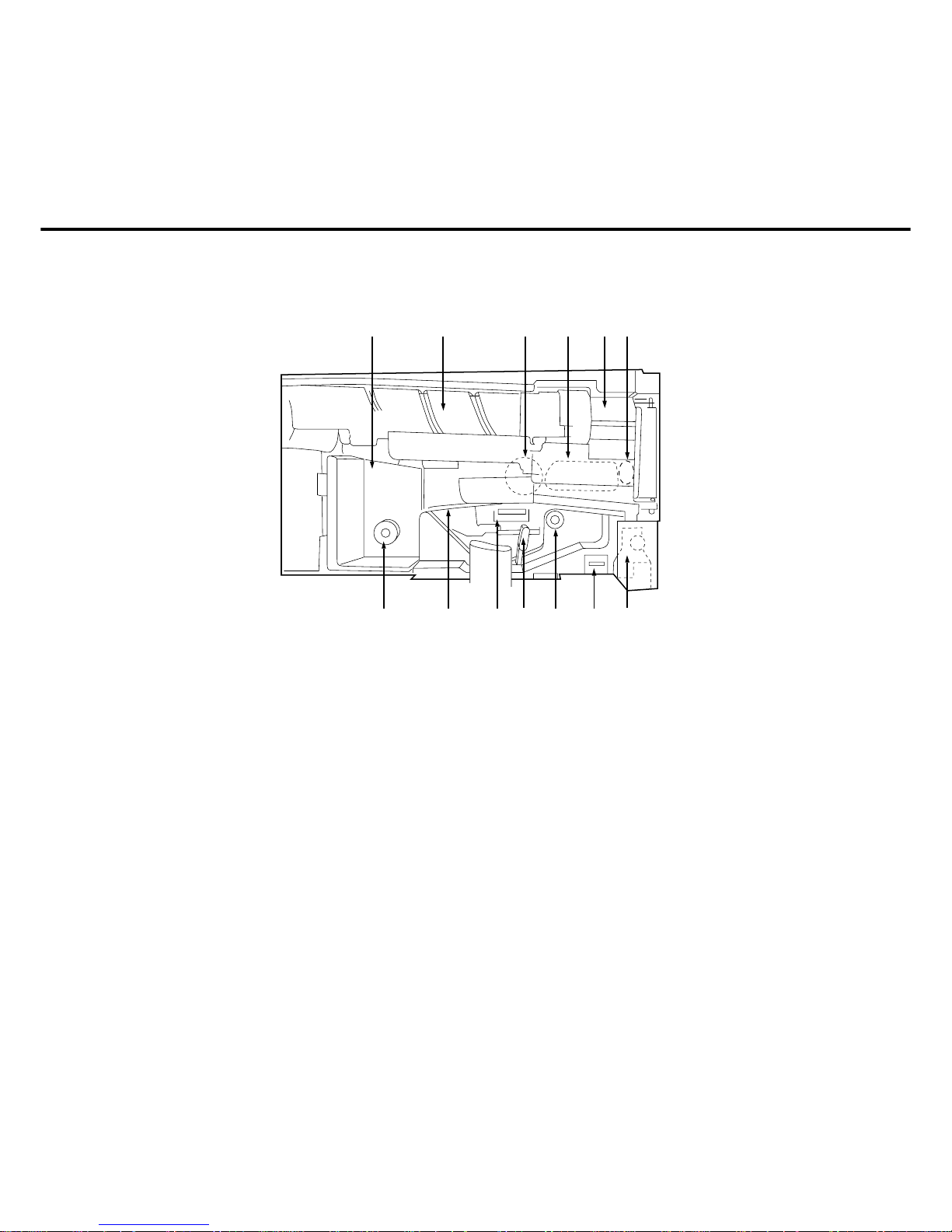
2. Inner view
1
23456
78910111213
1. Fuser area cover
2. Toner bottle
3. Drum unit
4. Developer unit
5. Toner hopper unit
6. Developer release lever
7. Waste toner bottle
8. Total counter
9. Manual paper feed knob
(Feed unit)
10. Paper transport handle
11. Transfer/Separation corona
12. Paper transport unit
13. Manual paper feed knob
(Fuser unit)
SV711
Introduction
1-15
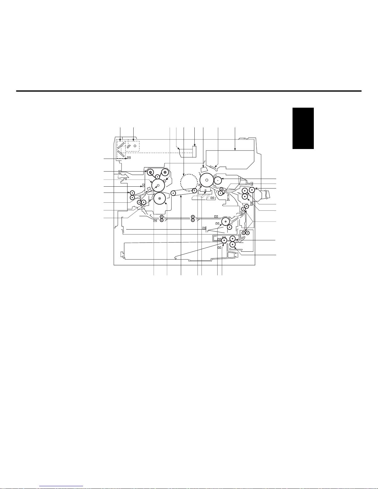
2. Inner view
1 Half-speed unit
2 Full-speed unit
3 Thermistor
4 Lens unit
5 Main motor
6 CCD unit
7 Charge corona
8 Slit glass
9 Laser unit
10 Magnetic roller
11 Registration roller
12 Bypass pick-up roller
13 Bypass paper feed roller
14 Bypass DFP roller
15 Middle roller
16 Paper feed roller
17 DFP roller
18 Pick-up roller
19 ADU Paper feed roller*
20 Transport / Separation corona
21 Drum
22 Transport belt
23 Pressure roller
24 Fuser lamp
25 Fuser separation finger (lower)
26 ADU guide roller*
27 Fuser separation finger (upper)
28 Paper exit roller
29 Paper exit sensor
30 Heat roller
31 Cleaning web roller
32 Full-speed unit home position sensor
1
32
31
30
29
28
27
26
25
24 23 22 20 19 18
17
16
15
14
13
12
11
10
21
23456789
*Included with the ADU unit. (Option: FP-D250/D350/D350H, Standard: FP-D450/D600)
1-16
3. Fan/Motor Location (FP-D250/D350/D350H)
Optics drive
motor
Toner bottle
motor
Dust collecting
fan
*
ADU paper
length guide
motor
* ADU paper
width guide
motor
*
ADU drive
motor
Optics fan
Main motor
Exhaust fan
Lifting motor
(lower stage)
Lifting motor
(upper stage)
Suction/
Ozone fan
* Included with the ADU unit
(Option)
and Printer unit.
(Option: FP-D250/D350, Standard: FP-D350H)
Developer Unit
cooling fan
*Printer controller
cooling fan
*Power supply
cooling fan

Introduction
1-17
4. Fan/Motor Location (FP-D450/D600)
Optics drive
motor
Toner bottle
motor
Dust collecting
fan
Optics fan
Main motor
Exhaust fan
Lifting motor
(lower stage)
Suction/
Ozone fan
* Included with the Printer unit.
(Option)
Developer Unit
cooling fan
*Printer controller
cooling fan
Power supply
cooling fan
ADU drive
motor
ADU paper
length guide
motor
ADU paper
width guide
motor

1-18
5. Sensor Location
Lamp unit
home position
Platen cover
open/close
Platen cover
angle
Original size
* ADU
detection
Toner density
Copy density
* ADU paper
length
* ADU paper
pass 1
Paper exit
Front cover
open/close
* ADU paper width
Paper level (lower stage)
* ADU paper
detection
* ADU paper
pass 2
Registration
roller paper pass
Paper detection
(lower stage)
Paper limit
(lower stage)
Middle roller paper pass
(upper/lower stage)
Waste toner
bottle
Total counter
Bypass paper
detection
Bypass paper size
Toner level
Toner bottle
home position
Paper feed cover
open/close
* Included with the ADU unit.
(Option: FP-D250/D350/D350H, Standard: FP-D450/D600)
Paper level
(upper stage : D250/D350/D350H)
Paper limit
(upper stage :
D250/D350/
D350H)
Paper detention
Introduction
1-19
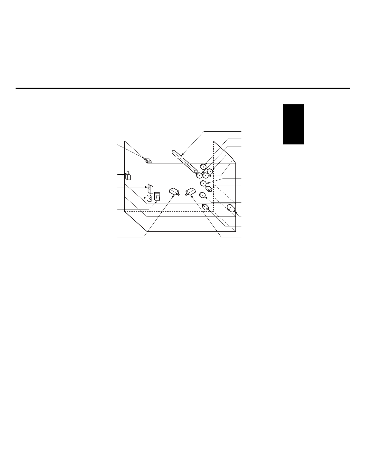
6. Solenoid/Clutch/Discharge lamp Location
Paper feed clutch
Registration roller
clutch
Discharge lamp
Middle roller clutch
Paper feed clutch
(lower stage)
* Paper exit
solenoid
Power switch
Door switch
* ADU clutch
Pick-up solenoid
(lower stage)
Recycle solenoid
* Included with the ADU unit.
(Option: FP-D250/D350/D350H, Standard: FP-D450/D600)
Laser unit
switch
Paper feed speed
control clutch
Separation
solenoid (FP-D450/D600)
Operation
Switch
(D450/D600)
Paper feed clutch
Pick-up solenoid
(upper stage :
D250/D350/D350H)
1-20
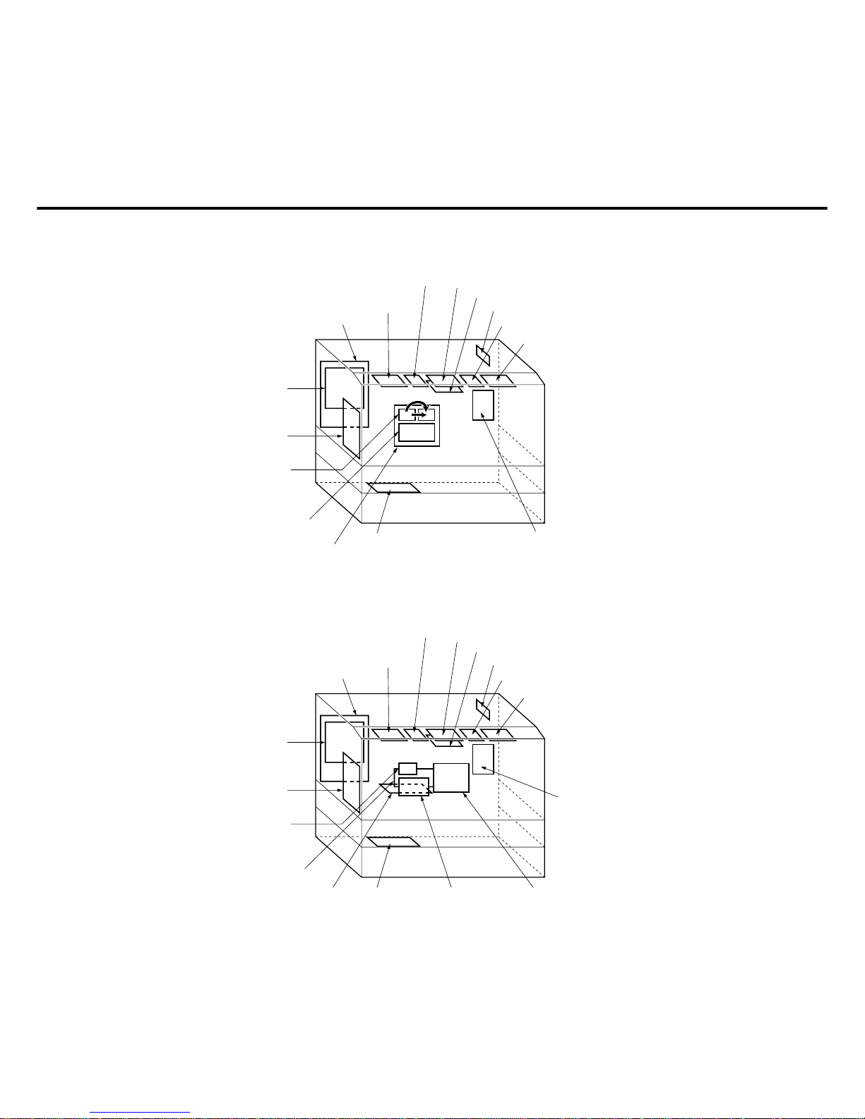
7. PCB Location (FP-D250/D350/D350H)
LVPS (Low voltage
power supply)
System Control
Main CPU
Automatic duplex
unit driver
(Option)
Control
panel B
Touch panel
Control panel
CPU
Control panel A
HVPS (High
voltage power supply)
AC driver
CCD control
*Control
panel D
*Control panel C
Printer controller
(option)
*NAC
8. PCB Location (FP-D450/D600)
LVPS (Low voltage
power supply)
Image
Processing
CPU
Automatic duplex
unit driver
(Option)
Control
panel B
Touch panel
Control panel
CPU
Control panel A
HVPS
(High voltage
power supply)
AC driver
CCD control
*Control
panel D
*Control panel C
Printer controller
(option)
NAC (option)
Printer
Controller
(Option)
System Controller
Introduction
1-21
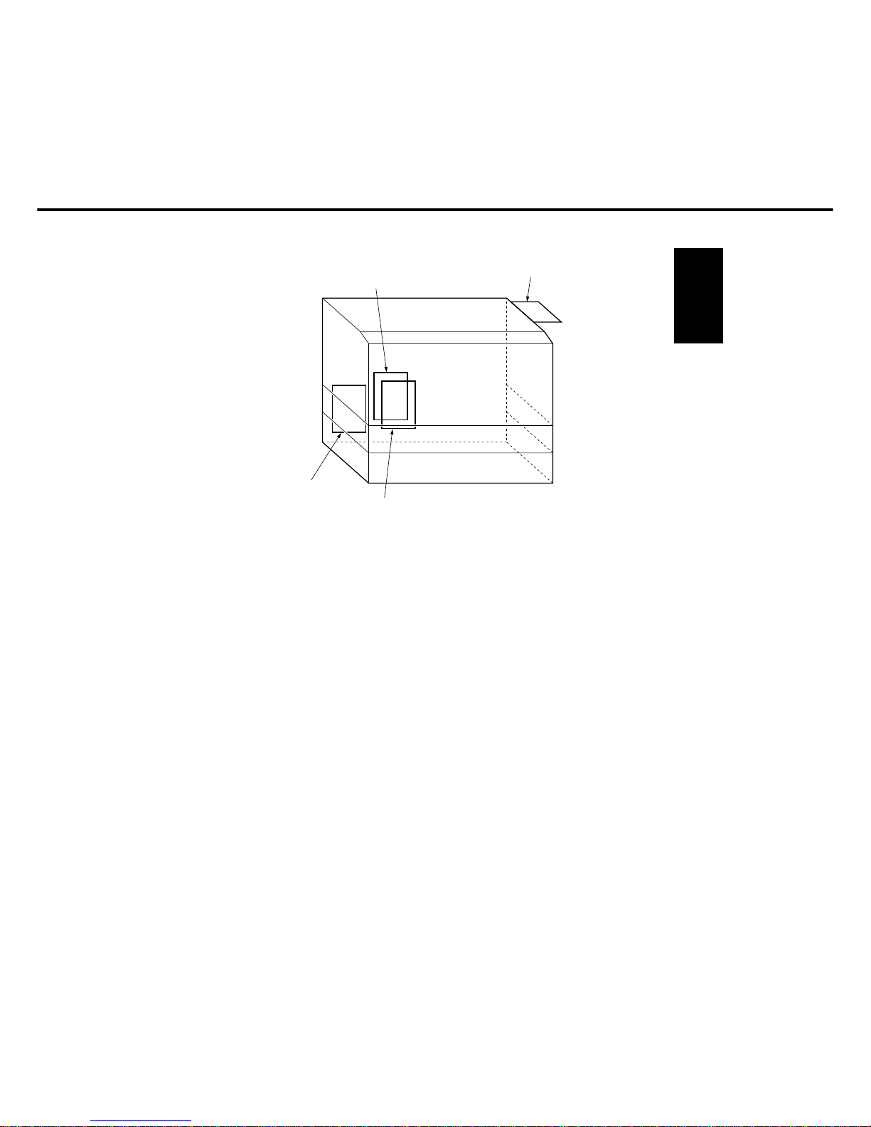
9. Hard Disk Drive / Zip Drive Location
*Zip drive
*Hard disk for filing
Hard disk for printer
(Option)
Hard disk for back-up (Option)
*
(Option: FP-D250/D350/D450/D600, Standard: FP-D350H)
 Loading...