

Page 1
Operating Instructions
<Operations and Settings>
HD Integrated Camera
Model No.
Model No.
Model No.
Model No.
Model No.
Model No.
Model No.
Model No.
AW‑HE40HWP
AW‑HE40HKP
AW‑HE40HWE
AW‑HE40HKE
AW‑HE40SWP
AW‑HE40SKP
AW‑HE40SWE
AW‑HE40SKE
● How the Operating Instructions are configured
<Basics>:
The <Basics> describes the procedure for basic operation and installation. Before installing this unit, be
sure to take the time to read through <Basics> to ensure that the unit will be installed correctly.
<Operations and Settings> (this manual):
This <Operations and Settings> describes how to operate the unit and how to establish its settings.
ENGLISH
SQW0456
F0715TY0
Page 2
Trademarks and registered trademarks
Abbreviations
● Microsoft®, Windows®, Windows® 7, Windows® 8,
Windows
®
8.1, Internet Explorer® and ActiveX® are
either registered trademarks or trademarks of Microsoft
Corporation in the United States and other countries.
®
● Intel
and Intel® CoreTM are trademarks or registered
trademarks of Intel Corporation in the United States and
other countries.
● Adobe
®
and Reader® are either registered trademarks or
trademarks of Adobe Systems Incorporated in the United
States and/or other countries.
● HDMI, the HDMI logo and High-Definition Multimedia
Interface are the trademarks or registered trademarks
of HDMI Licensing LLC in the United States and other
countries.
● microSDXC Logo is a trademark of SD-3C, LLC.
● Apple, Mac, OS X, iPhone, iPod Touch, iPad, and Safari
are registered trademarks of Apple Inc., in the United
States and other countries.
● Android
TM
is a trademark of Google Inc.
● Other names of companies and products contained
in these Operating Instructions may be trademarks or
registered trademarks of their respective owners.
About copyright and licence
Distributing, copying, disassembling, reverse compiling,
reverse engineering, and also exporting in violation of export
laws of the software provided with the unit are expressly
prohibited.
The following abbreviations are used in this manual.
● Microsoft
®
Windows® 7 Professional SP1 32/64-bit is
abbreviated to “Windows 7”.
● Microsoft
®
Windows® 8 Pro 32/64-bit is abbreviated to
“Windows 8”.
● Microsoft
®
Windows® 8.1 Pro 32/64-bit is abbreviated to
“Windows 8.1”.
● Windows
Explorer
Windows
®
Internet Explorer® 8.0, Windows® Internet
®
9.0, Windows® Internet Explorer® 10.0 and
®
Internet Explorer® 11.0 are abbreviated to
“Internet Explorer”.
● microSDHC memory cards and microSDXC memory
cards are abbreviated to “SD cards”.
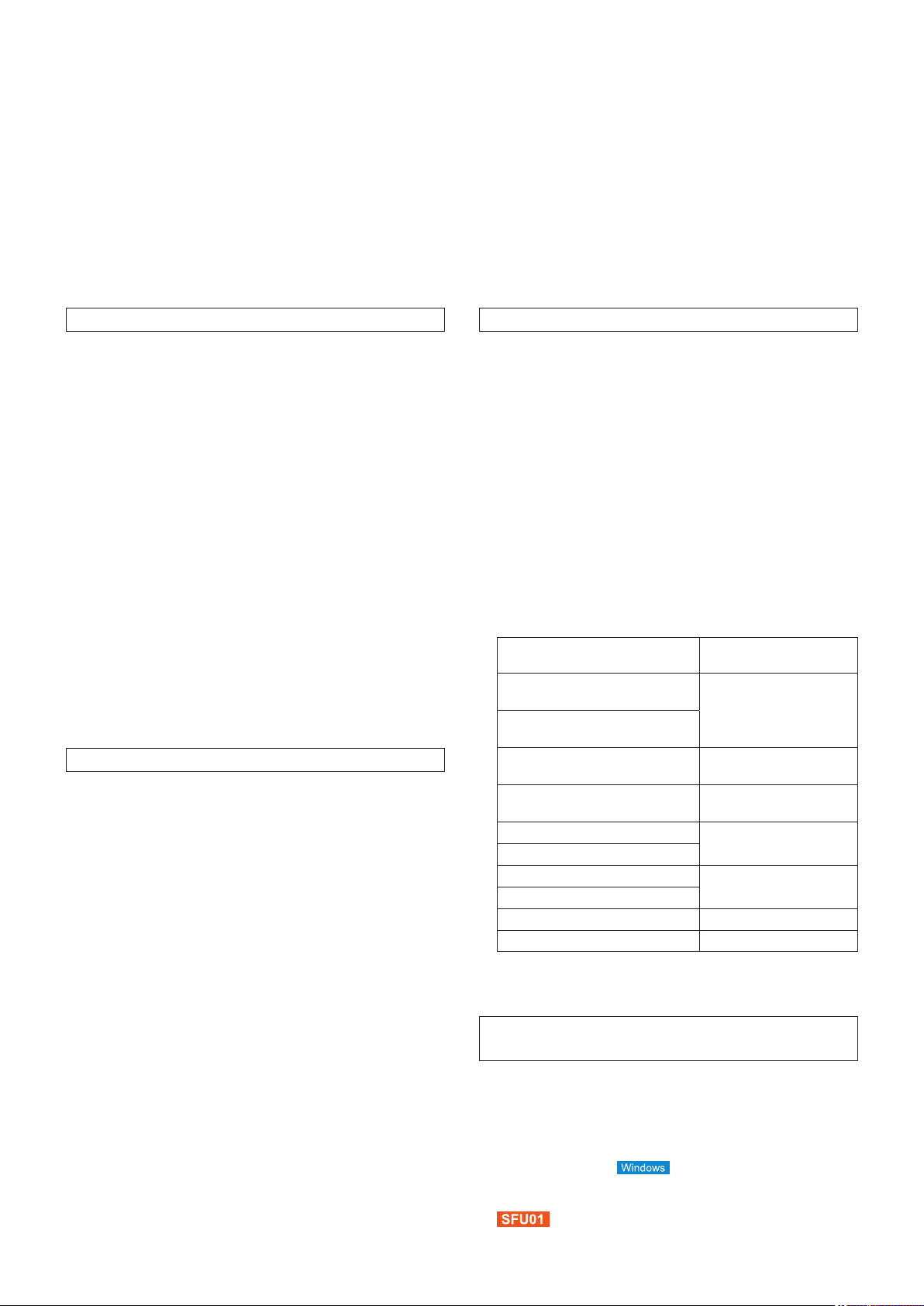
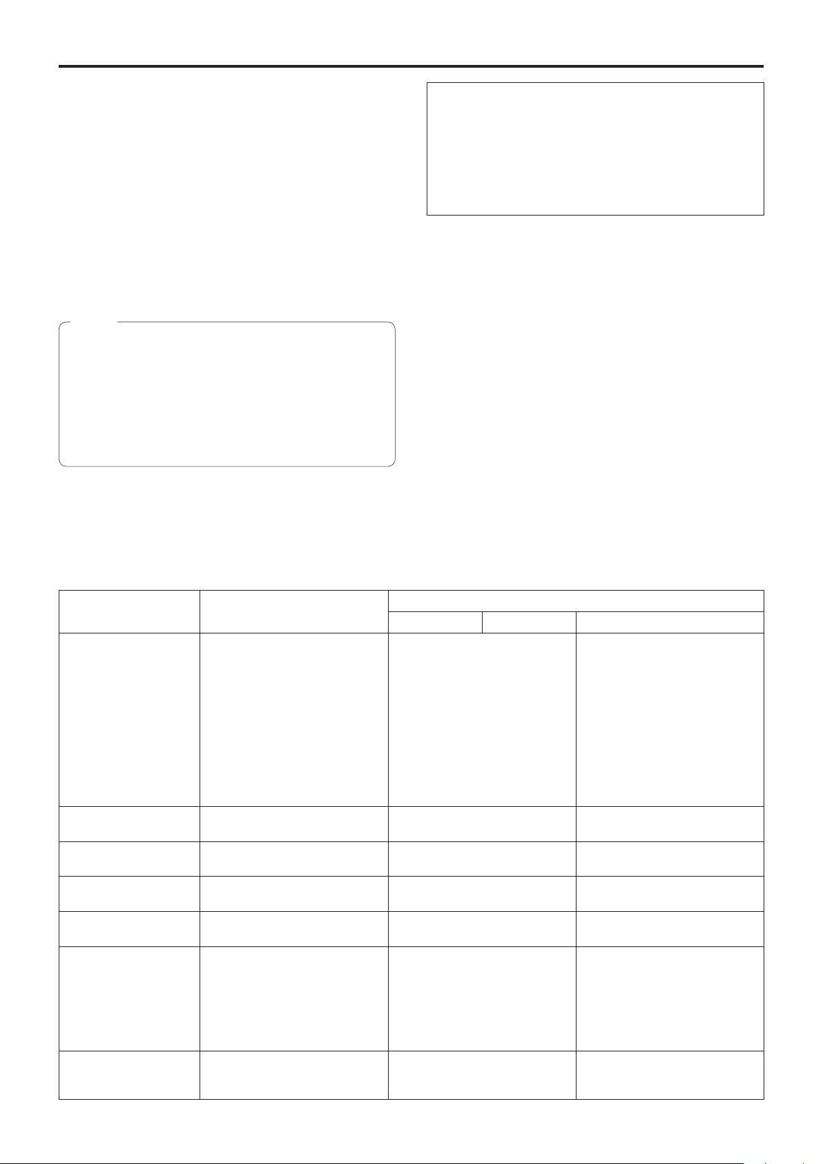
For the purposes of this manual, the model numbers of the
units are given as listed in the table below.
Model number
of unit
AW-HE40HWP, AW-HE40HKP,
AW-HE40HWE, AW-HE40HKE
AW-HE40SWP, AW-HE40SKP,
AW-HE40SWE, AW-HE40SKE
AW-HE40HWP, AW-HE40HKP,
AW-HE40HWE, AW-HE40HKE
AW-HE40SWP, AW-HE40SKP,
AW-HE40SWE, AW-HE40SKE
AW-HS50N
AW-HS50E
AW-RP50N
AW-RP50E
AW-RP120G AW-RP120
AK-HRP200G AK-HRP200
Model number
given in manual
AW-HE40
AW-HE40H
AW-HE40S
AW-HS50
AW-RP50
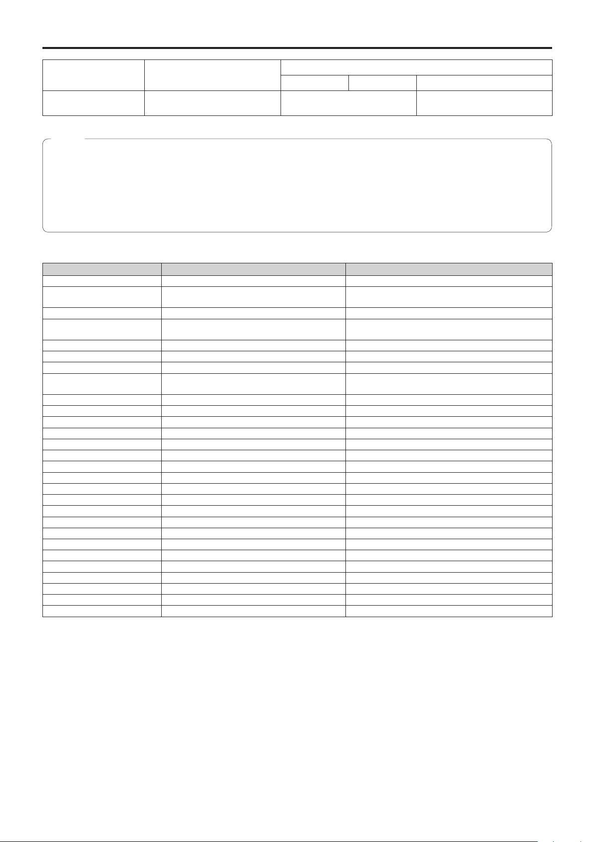
Illustrations and screen displays featured in
the manual
● What is shown in the manual’s illustrations and screen
displays may differ from how it is actually appears.
● The screenshots are used in accordance with the
guidelines of Microsoft Corporation.
● Functions which can be used by Windows only are
indicated using the
mark.
● The functions that become available after activation
(registration of the unlock key code) are indicated by the
mark.
2
Page 3

Contents
Before use 4
Overview
Required personal computer environment
Disclaimer of warranty
Network security
Basic shooting operations
How to turn the power on and off
Turning the power on
Turning the power off
Priority mode (Priority Mode)
Selecting the units
Selecting the shooting modes (scene files)
Types of shooting modes
How to select the shooting mode
Shooting
What to do when encountering problems in the
basic shooting operations
More advanced operations
Manual shooting
Manually adjusting the focus
Manually adjusting the iris
Manually adjusting the shutter speed
Manually adjusting the gain
Preset memories
White balance adjustment
White balance adjustment
Black level (master pedestal) adjustment
Black level (master pedestal) adjustment
Basic operations
When performing the operations using the wireless
remote control
Operations on the AW-RP50 Remote Camera
Controller
Operations on the AW-RP120 Remote Camera
Controller
Operations on the AK-HRP200 Remote Operation
Panel
Camera menu items
Setting the camera menu items
Top Menu screen
Camera screen
(when Full Auto is selected)
Camera screen
(when Manual1 to 3 is selected)
Contrast 1/2 screen
Contrast 2/2 screen
Picture 1/3 screen
Picture 2/3 screen
Picture 3/3 screen
16-axis color matrix
System screen
Output screen
4
4
5
5
6
7
7
7
8
9
9
9
10
11
12
13
14
14
14
15
15
16
17
17
21
21
22
24
25
29
32
35
35
35
36
36
37
38
39
40
41
42
43
44
Others 1/4 screen
Others 2/4 screen
Others 3/4 screen
Others 4/4 screen
Maintenance screen
Firmware Version screen
IP Network screen
Camera menu item table
Displaying the web screen
Displaying the web screen using a personal
computer
Switching between the Live screen [Live] and Web
setup screen [Setup]
Web screen operations
Live screen [Live] : Single display mode
Live screen [Live] : Multi display mode
Web screen configurations
Logging into the Web setup screen [Setup]
Web setup screen [Setup]
Basic screen [Basic]
Image screen [Image/Audio]
Multi screen setup screen [Multi-screen setup]
User management screen [User mng.]
Network setup screen [Network]
Maintenance screen [Maintenance]
Recording to and playing back from
a memory card
Web camera functions
Controllable functions
Displaying the web screen using a mobile terminal
Limiters
Activation
Troubleshooting
Index
120
Basic limiter operations
Setting the limiters
Releasing the limiters
Resetting the limiters
122
135
46
47
48
49
50
50
51
52
55
55
56
57
63
64
65
68
109
113
113
120
121
121
121
124
57
62
63
86
87
89
104
116
3
Page 4
Before use
■Overview
● The unit is a compact full HD camera integrated with a
pan-tilt head and featuring a 1/2.3-type MOS sensor and
digital signal processor (DSP).
● In addition to its optical 30x zoom lens, the unit comes
with a 16x digital zoom allowing you to capture highquality images that overflow with ambience. Using i.Zoom
allows up to 40x zoom while maintaining HD quality.
● The AW-HE40H is an HDMI model that is suited for
transmitting images from video conferences, for example,
and supports IP video transmission and IP control.
The AW-HE40S is an SDI output model that is suited for
content production and supports IP video transmission
and IP control.
● When a controller is connected, camera operations can be
performed smoothly via IP control or serial control.
● The unit features a Night mode, making it possible to
shoot even under very-low-brightness conditions by
exposing subjects to infrared rays.
● When the unit is connected to a computer via an IP
network, it can be operated via a web browser while
viewing the camera images on the screen.
● Connection with a Panasonic camera controller is also
possible via Panasonic’s proprietary serial communication
format.
● The unit supports standard serial communication formats,
allowing connection to commercially available controllers.
● The unit is available in two color variations (white or black)
to suit your intended application and environment.
● Equipped with a newly developed codec engine, the unit
can output Full HD images at up to 60 fps via a network.
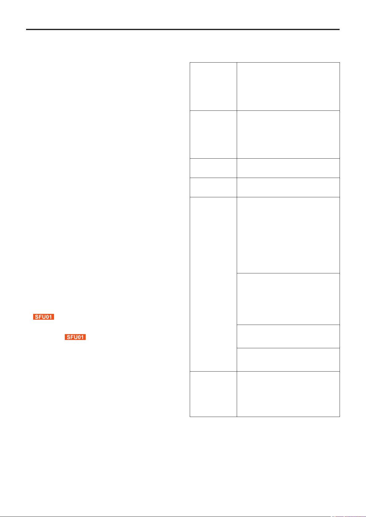
■Required personal computer
environment
CPU
Memory
Network
function
Image display
function
Supported
operating
system and
Web browser
When using 1080/60p [59.94Hz] and
1080/50p [50Hz]
Intel® CoreTM i7 3.4 GHz or higher
recommended
Other than above
Intel® CoreTM2 Duo 2.4 GHz or higher
recommended
For Windows:
1 GB or higher
(2 GB or higher for Microsoft® Windows®
8.1, Microsoft® Windows® 8, Microsoft®
Windows® 7 64-bit edition)
For Mac:
2 GB or more
10BASE-T or 100BASE-TX port × 1
Resolution: 1024 × 768 pixels or more
Color generation: True Color 24-bit or more
Windows
Microsoft® Windows® 8.1 Pro
64-bit/32-bit *1
Windows® Internet Explorer® 11.0
Microsoft
64-bit/32-bit *1
Windows® Internet Explorer® 10.0 *
Microsoft® Windows® 7 Professional SP1
64-bit/32-bit *2
Windows® Internet Explorer® 8.0 / 9.0 /
10.0 / 11.0 *
Mac
OS X v10.8
Safari 6.2
OS X v10.9
Safari 7.1
OS X v10.10
Safari 8.0
®
Windows® 8 Pro
3
1
● Changing the Priority Mode enables operation for various
applications.
4
iPhone / iPad / iPod touch
iOS 8.3
Standard browser
Android
Android OS 4.4
Standard browser
Other
1
*
: Use the desktop version of Internet Explorer. (Internet Explorer
for Windows UI is not supported.)
*2: Windows® XP compatibility mode is not supported.
*3: The 64-bit version of Internet Explorer® is not supported.
CD-ROM drive
(for using the Operating Instructions and
various software)
®
Reader®
Adobe
(for viewing the Operating Instructions on the
CD-ROM)
Page 5
Before use
(continued)
IMPORTANT
● Failure to provide the required personal computer
environment may slow down the delineation of
the images on the screen, make it impossible for
the web browser to work and cause other kinds of
problems.
● Use the desktop version of Internet Explorer. (Internet
Explorer for Windows UI is not supported.)
● For the most recent information on compatible operating
systems and web browsers, visit the support desk at the
following web site.
http://pro-av.panasonic.net/
■Disclaimer of warranty
IN NO EVENT SHALL Panasonic Corporation BE LIABLE
TO ANY PARTY OR ANY PERSON, EXCEPT FOR
REPLACEMENT OR REASONABLE MAINTENANCE OF
THE PRODUCT, FOR THE CASES, INCLUDING BUT NOT
LIMITED TO BELOW:
A ANY DAMAGE AND LOSS, INCLUDING WITHOUT
LIMITATION, DIRECT OR INDIRECT, SPECIAL,
CONSEQUENTIAL OR EXEMPLARY, ARISING OUT
OF OR RELATING TO THE PRODUCT;
B PERSONAL INJURY OR ANY DAMAGE CAUSED BY
INAPPROPRIATE USE OR NEGLIGENT OPERATION
OF THE USER;
C UNAUTHORIZED DISASSEMBLE, REPAIR OR
MODIFICATION OF THE PRODUCT BY THE USER;
D INCONVENIENCE OR ANY LOSS ARISING WHEN
IMAGES ARE NOT DISPLAYED, DUE TO ANY
REASON OR CAUSE INCLUDING ANY FAILURE OR
PROBLEM OF THE PRODUCT;
E ANY PROBLEM, CONSEQUENTIAL
INCONVENIENCE, OR LOSS OR DAMAGE, ARISING
OUT OF THE SYSTEM COMBINED BY THE DEVICES
OF THIRD PARTY;
F ANY DEMANDS FOR COMPENSATION, CLAIMS,
ETC. OCCASIONED BY THE INFRINGEMENT OF
PRIVACY BY INDIVIDUALS OR ORGANIZATIONS
WHOSE IMAGES WERE SHOT BY THE USER
BECAUSE THESE IMAGES (INCLUDING THE
RECORDINGS MADE) WERE MADE AVAILABLE
BY THE USER BECAUSE IN THE PUBLIC DOMAIN
FOR SOME REASON OR OTHER OR BECAUSE THE
IMAGES ENDED UP BEING USED FOR PURPOSES
OTHER THAN THE ONE DESCRIBED ABOVE;
G LOSS OF REGISTERED DATA CAUSED BY ANY
FAILURE.
H Indemnity about recorded content
Panasonic does not accept any responsibility for
damages directly or indirectly due to any type of
problems that result in loss of recording or edited
content, and does not guarantee any content if
recording or editing does not work properly. Likewise,
the above also applies in a case where any type of
repair is made to this unit.
■Network security
As you will use the unit connected to a network, your
attention is called to the following security risks.
A Leakage or theft of information through the unit
B Use of the unit for illegal operations by persons with
malicious intent
C Interference with or stoppage of the unit by persons
with malicious intent
It is your responsibility to take precautions such as those
described below to protect yourself against the above
network security risks.
● Use the unit in a network secured by a firewall, etc.
● If the unit is connected to a network that includes personal
computers, make sure that the system is not infected
by computer viruses or other malicious entities (using
a regularly updated antivirus program, anti-spyware
program, etc.).
● Protect your network against unauthorized access by
restricting users to those who log in with an authorized
user name and password.
● After accessing the unit as an administrator, be sure to
close all web browsers.
● Change the administrator password periodically.
● Restrict access to the unit by authenticating the users, for
example, to prevent setting information stored on the unit
from leaking over the network.
● Do not install the camera in locations where the camera or
the cables can be destroyed or damaged by persons with
malicious intent.
● Avoid connections that use public lines.
Concerning user authorization
User authentication on the unit can be performed via digest
authentication or basic authentication. If basic authentication
is used without using a dedicated line equipped with an
authentication function, password leaks may occur.
Usage restrictions
Use of the same segment is recommended for the network
in which the unit and the controller or personal computer are
connected.
If the equipment uses connections with different segments,
events based on the settings inherent to the network
equipment, for instance, may occur so check this thoroughly
prior to operation.
5
Page 6

Basic shooting operations
1 Set the subject brightness to the appropriate
level.
2 Turn on the power of all the units and devices
in the system.
3 Select the unit to be operated.
Even when using only one unit, it must still be selected
from the wireless remote control or controller.
4 Select the shooting mode.
Select one of the four (Full Auto, Manual1, Manual2 and
Manual3) preset shooting modes (scene files), each of
which corresponds to a set of circumstances in which
the subject will be shot.
Select the mode that satisfies the shooting conditions
and suits your preferences.
When continuing to shoot in the same circumstances,
there is no need to select another mode.
5 Start shooting.
(After shooting, turn off the power of all the
units and devices in the system.)
With the basic operations, it is assumed that the focus, iris
and white balance will be adjusted automatically (as per the
factory settings).
If the settings have already been changed and the original
settings are to be restored, refer to the “What to do when
encountering problems in the basic shooting operations”
(page 12) and “Camera screen” (page 36) in “Camera menu
items”.
Note
● If “Full Auto” has been selected as the setting for
Scene on the camera menu, for example, all the auto
settings will be turned on, and manual operations will
no longer be possible for some of the items.
6
Page 7

How to turn the power on and off
■Turning the power on
When performing the operations
using the wireless remote control
1 Set all the power switches of the units and
devices connected in the system to ON.
● The unit does not have a power switch.
When power is supplied to it, the status display lamp
will light up orange.
2 Press one of the [CAM1] to [CAM4] buttons on
the wireless remote control to select the unit.
3 Press the [ON/STANDBY] button on the
wireless remote control for 2 seconds.
The POWER ON mode is established, images are
output, and control can be exercised.
● The unit’s status display lamp now lights up green.
Notes
● It takes about 30 seconds per unit for the initial
settings operation to be completed. During this
period, the unit cannot be operated.
● The unit stores its STANDBY / POWER ON mode
status in the memory.
● If the power supply is cut off while the operation is
in POWER ON mode, the operation will transferred
to the POWER ON mode the next time power is
supplied.
● When transferring to the STANDBY mode
(Status display lamp: Orange)
The pan/tilt position is stored in the memory, and the
pan/tilt unit is moved so that it points backwards.
● When transferring to the POWER ON mode
(Status display lamp: Green (after the initial setting
operation is completed))
The pan/tilt unit is moved to the position which was
stored in the memory when the transition to the
STANDBY mode was made.
● POWER ON preset
The pan/tilt unit is moved to the setting, which was
established immediately prior to the transition to the
STANDBY mode, when the power has been turned
on.
● If the power is turned off without transferring to the
STANDBY mode, the pan/tilt unit position will not
be stored in the memory or reflected in the POWER
ON preset. The previous POWER ON preset will be
applied.
■Turning the power off
When performing the operations
using the wireless remote control
1 Press one of the [CAM1] to [CAM4] buttons on
the wireless remote control to select the unit.
2 Press the [ON/STANDBY] button on the
wireless remote control for 2 seconds.
The unit enters STANDBY mode.
● The unit’s status display lamp now lights up orange.
3 If a multiple number of units are used, repeat
1 and 2 as required.
steps
4 Set all the power switches of the units and
devices connected in the system to OFF.
When performing the operations using the controller
When using an AW-RP50, AW-RP120 or AK-HRP200:
Refer to the Operating Instructions of the controller.
4 If a multiple number of units are going to be
used, repeat steps
The unit’s status display lamp blinks green when a signal
matched by the remote control ID has been received, and
it blinks orange when a signal that is not matched by the
remote control ID has been received.
2 and 3 as required.
7
Page 8

Priority mode (Priority Mode)
Changing the priority mode enables the unit to perform operation for various applications. (page 44, page 65)
IP:
Enables IP image transmission over multiple channels. The IP transmission of H.264 images is also supported.
SD card:
Inserting an SD card (optional accessory) into the unit enables recording H.264 images to the SD card.
The data recorded to the SD card can be played back on the Web screen, downloaded to a personal computer, and
transferred to an FTP server.
USB:
Enables the unit to be used as a Web camera.
The camera can also be controlled from a personal computer.
Functions that can be and functions that cannot be controlled simultaneously
Priority Mode MJPEG IP streaming H.264 IP streaming
IP
SD card
USB
1920×1080
1280×720
640×360
320×180
640×360
320×180
640×360
320×180
1920×1080
1280×720
640×360
320×180
—
— —
Recording MP4 to SD
card
— —
1920×1080
1280×720
USB Video Class
1920×1080
1280×720
—
640×360
● For the restrictions on IP streaming, refer to page 72.
8
Page 9

Selecting the units
When performing the operations
using the wireless remote control
When performing the operations using the controller
When using an AW-RP50, AW-RP120 or AK-HRP200:
1 Press the [CAM1], [CAM2], [CAM3] or [CAM4]
button.
The unit’s status display lamp blinks green when a signal
matched by the remote control ID has been received,
and it blinks orange when a signal that is not matched by
the remote control ID has been received.
Refer to the Operating Instructions of the controller.
Selecting the shooting modes (scene files)
■Types of shooting modes
The unit has four preset shooting modes, each of which
corresponds to a set of circumstances in which the subject
will be shot.
Select the mode that satisfies the shooting conditions and
suits your preferences.
The settings can be changed by menu operations.
● The results of the white balance and other adjustments
are stored in the memory separately by shooting mode.
Be absolutely sure to select the shooting mode before
making any adjustments.
Full Auto
Adjust the shutter speed, aperture, and white balance
automatically.
Manual1
The settings of your preferences can be established
in line with the shooting scene, lighting and other
conditions.
Manual2
The settings of your preferences can be established
in line with the shooting scene, lighting and other
conditions.
Note
● If “Full Auto” has been selected as the setting for
Scene on the camera menu, for example, all the auto
settings will be turned on, and manual operations will
no longer be possible for some of the items.
Manual3
The settings of your preferences can be established
in line with the shooting scene, lighting and other
conditions.
9
Page 10
Selecting the shooting modes (scene files)
(continued)
■How to select the shooting
mode
When performing the operations
using the wireless remote control
2, 8
1
3, 5, 7
4, 6, 7
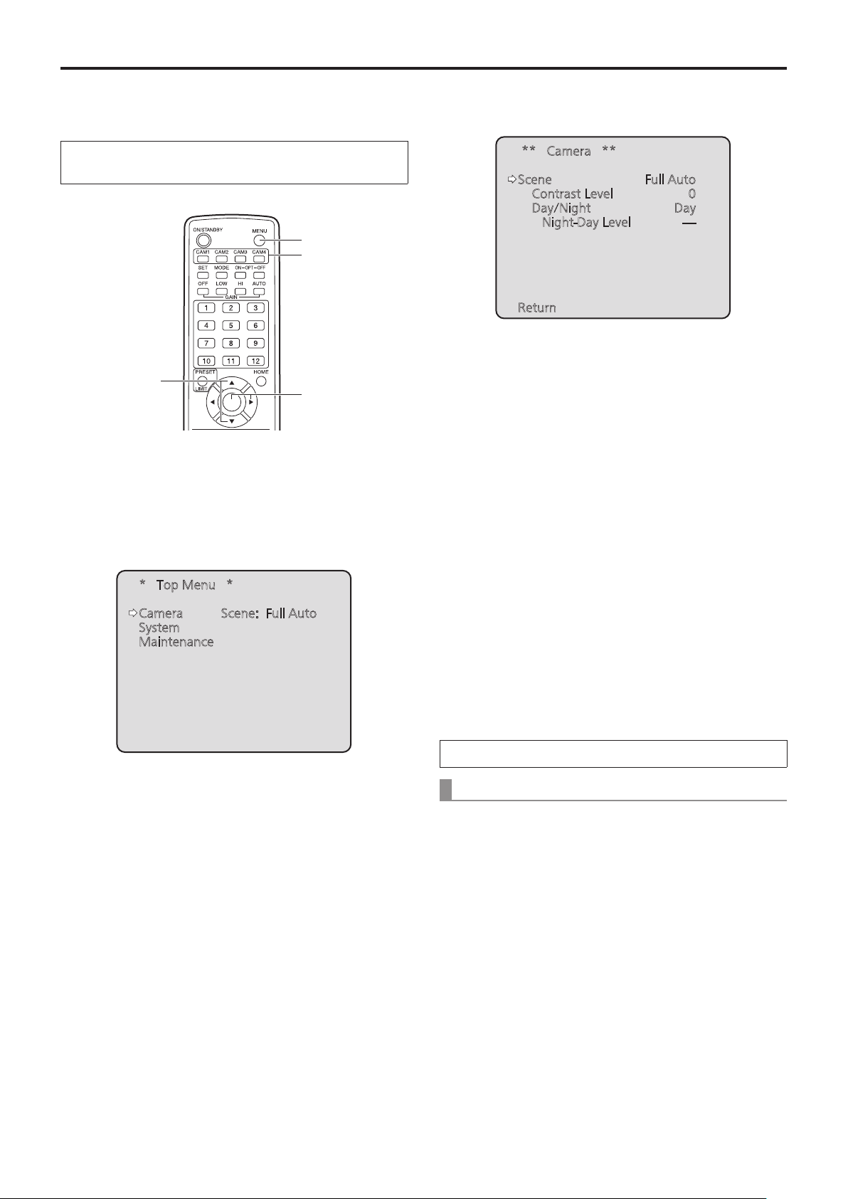
1 Press the [CAM1], [CAM2], [CAM3] or [CAM4]
button to select the unit.
2 Press the [MENU] button for 2 seconds.
The Top Menu is displayed.
4 Press the [
The “Camera” sub-menu is displayed on the monitor.
] button.
○
** Camera **
Scene Full Auto
Contrast Level 0
Day/Night Day
Night-Day Level ----
Return
5 Press the [▲] or [▼] button to bring the cursor
to “Scene”.
6 Press the [
The shooting mode blinks.
] button.
○
7 Press the [▲] or [▼] button to select the
shooting mode (Full Auto, Manual1, Manual2 or
Manual3) to be used, and press the [○] button
to enter the selection.
* Top Menu *
Camera Scene: Full Auto
System
Maintenance
3 Press the [▲] or [▼] button to bring the cursor
to “Camera”.
8 Press the [MENU] button for 2 seconds.
The camera menu display is exited.
When performing the operations using the controller
When using an AW-RP50, AW-RP120 or AK-HRP200:
Refer to the Operating Instructions of the controller.
10
Page 11
Shooting
When performing the operations
using the wireless remote control
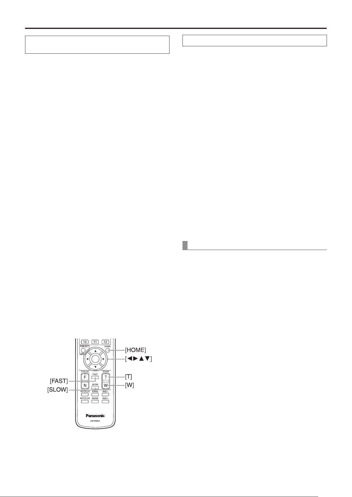
Changing the camera’s direction
●
Moving the camera toward the left or right (panning):
Press the [◄] or [►] button.
Moving the camera up or down (tilting):
Press the [▲] or [▼] button.
Moving the camera diagonally:
Press the [▲] or [▼] button and [◄] or [►] button at
the same time.
Returning the camera to the reference position:
Press the [HOME] button for 2 seconds.
Using the zoom function
●
Zooming in (the subject becomes magnified in size):
Press the [T] button of [ZOOM].
Zooming out (the subject becomes reduced in size):
Press the [W] button of [ZOOM].
When performing the operations using the controller
Changing the camera’s direction
●
Moving the camera toward the left or right (panning):
Tilt the [PAN/TILT] lever toward L or R.
Moving the camera up or down (tilting):
Tilt the [PAN/TILT] lever toward UP or DOWN.
Moving the camera diagonally:
Tilt the [PAN/TILT] lever diagonally.
Returning the camera to the reference position:
If the controller has a [HOME] button, press the
[HOME] button.
Using the zoom function
●
Zooming in (the subject becomes magnified in size):
Tilt the [ZOOM] lever toward the TELE direction.
Zooming out (the subject becomes reduced in size):
Tilt the [ZOOM] lever toward the WIDE direction.
Switching the direction or zoom speed
●
Changing the direction or zoom at high speed:
Press the [FAST] button.
When this button is held down, the speed can be set to
an even higher speed.
When it is tapped, the normal speed (high speed) is
restored.
Changing the direction or zoom at low speed:
Press the [SLOW] button.
When this button is held down, the speed can be set to
an even lower speed.
When it is tapped, the normal speed (low speed) is
restored.
The lens focus control speed is also changed at the same
time.
Changing the pan/tilt direction and zoom
●
speed
When using an AW-RP50, AW-RP120 or AK-HRP200:
Refer to the Operating Instructions of the controller.
11
Page 12

What to do when encountering problems in the basic shooting operations
If the trouble is not resolved by taking the action suggested
below, refer to “Troubleshooting” (page 124).
When performing the operations
using the wireless remote control
The unit does not move.
● Press the [CAM1], [CAM2], [CAM3] or [CAM4] button to
select the unit which is to be operated.
If only one unit is being used, it is normally selected using
the [CAM1] button.
● Check that the IR ID has been set correctly. (page 47,
page 84)
● If the unit’s status display lamp is off or lights up orange, it
means that the unit’s power is not on.
Refer to “Turning the power on” (page 7), and turn on the
power.
● If the unit’s status display lamp does not blink even when
the wireless remote control is operated near the unit’s
wireless remote control signal light-sensing area, it means
that the wireless remote control’s batteries have run down.
Replace the batteries.
Multiple color bands (color bars) are
displayed.
Press the [MODE] button to switch to the camera picture.
The menu screen is displayed.
Press the [MENU] button for 2 seconds to exit the camera
menu.
The lens focus is not adjusted automatically.
Press the [A/FOCUS] button to switch to auto focusing.
When performing the operations using the controller
The unit does not move.
● Select the unit to be operated by following the procedure
below.
When using an AW-RP50, AW-RP120 or AK-HRP200:
Refer to the Operating Instructions of the controller.
● If the unit’s status display lamp is off or lights up orange, it
means that the unit’s power is not on.
Refer to “Turning the power on” (page 7), and turn on
the power.
Multiple color bands (color bars) are
displayed.
Press the [BARS] button to switch to the camera picture.
The menu screen is displayed.
Press the [CAMERA OSD] button to exit the camera menu.
The lens focus is not adjusted automatically.
Press the [AUTO] button for focus control to switch to auto
focusing.
The camera picture is too light or too dark.
● Press the [AUTO] button for IRIS to switch to auto lens iris
adjustment.
● Press the [AUTO] button for GAIN to switch to auto gain
adjustment.
The camera picture is too light or too dark.
1. Press the [A/IRIS] button to switch the lens iris
adjustment to auto.
2. Press the [AUTO] button of [GAIN] to switch the gain
adjustment to auto.
Something is wrong with the coloring of the
camera pictures.
Refer to “Auto tracking white adjustment (ATW)” (page 19),
and switch to “ATW”.
12
Something is wrong with the coloring of the
camera pictures.
Refer to “Auto tracking white adjustment (ATW)” (page 19),
and switch to “ATW”.
Page 13

More advanced operations
Manual shooting (pages 14 to 15)
● Manual adjustment of focus
● Manual adjustment of iris
● Manual adjustment of shutter speed
● Manual adjustment of gain
Preset memories (page 16)
● Up to 100 settings for the camera direction (panning and
tilting), zoom, focus, iris, gain up and white balance can be
registered in the preset memories, and called.
● The number of settings that can be registered and
called depends on the type of wireless remote control
(12 settings) or controller that is used for operation.
White balance adjustment
(pages 17 to 20)
● This adjustment is performed to express the white
accurately. Its setting also has an effect on the color tones
of the entire screen.
● It must be performed when using the unit for the first
time or when the unit has not been used for a prolonged
period.
● It must be performed when the lighting conditions or
brightness has changed.
● Once the white balance has been attained, no further
adjustment is required provided that the unit is going to be
used under the same conditions.
Black level (master pedestal) adjustment
(page 21)
● This adjustment is performed to align the black level
(pedestal level) of a multiple number of cameras.
13
Page 14
Manual shooting
■Manually adjusting the focus
The lens focus can be adjusted manually.
When performing the operations
using the wireless remote control
1 Press the [M/FOCUS] button to switch the
focus to manual adjustment.
2 Press the [F] or [N] button of [FOCUS] to adjust
the focus.
When the [F] button is pressed, the focus moves further
away (far); conversely, when the [N] button is pressed, it
moves nearer (near).
The speed of focusing and other adjustments can
be switched to fast or slow by pressing the [FAST] or
[SLOW] button, respectively.
3 If necessary, press the [A/FOCUS] button to
return the focus to the automatic adjustment.
■Manually adjusting the iris
The lens iris can be adjusted manually.
When performing the operations
using the wireless remote control
1 Press the [M/IRIS] button to switch the iris to
manual adjustment.
2 Adjust the iris using the [IRIS +] or [IRIS –]
button.
Press the [IRIS +] button to adjust the lens iris in the
opening direction; conversely, press the [IRIS –] button to
adjust the lens iris in the closing direction.
3 If necessary, press the [A/IRIS] button to return
the iris to the automatic adjustment.
When performing the operations using the controller
When using an AW-RP50, AW-RP120 or AK-HRP200:
Refer to the Operating Instructions of the controller.
Note
● When the focus is set to manual, the subject may
go out of focus during panning, tilting and zooming.
Therefore, the unit comes with a function which
compensates for this. (Focus compensation during
zooming function: Focus ADJ With PTZ.) (page 46,
page 81, page 84)
When performing the operations using the controller
When using an AW-RP50, AW-RP120 or AK-HRP200:
Refer to the Operating Instructions of the controller.
● In Night mode, the iris is set to open as a measure to
prevent video spying.
Adjust the brightness at the light source.
14
Page 15
Manual shooting
(continued)
■Manually adjusting the shutter
speed
The shutter speed can be set using two methods. One is
a method that specifies the time (where a time such as
1/250 sec. is designated), and the other is a method that
specifies the frequency (where synchro scan, 60.15 Hz, etc.
is designated).
When shooting a TV screen or PC monitor screen, the
horizontal noise generated when the screen is shot can
be minimized by adjusting the frequency to the screen
frequency using synchro scan.
Note
● The shutter speed cannot be adjusted manually when
HDR is set to “Low” or “High”. (page 40)
When performing the operations
using the wireless remote control
Perform the adjustments on the Camera menu.
For further details, refer to the [Shutter Mode] and
[Step/Synchro] items on page 37.
■Manually adjusting the gain
There are two ways to adjust the gain. One way involves
using the buttons on the wireless remote control or controller;
the other way involves using the Camera menu or Web
setting.
The gain can be adjusted more precisely using the Camera
menu or Web setting.
For further details, refer to the [Gain] item on page 37 and
page 75.
Notes
● When Shooting mode (Scene) on the AW-HE40 is set
to “Full Auto”, the gain cannot be manually adjusted
(as the camera is locked in auto mode).
For details, refer to “Selecting the shooting modes
(scene files)” (pages 9 to 10).
● The gain cannot be adjusted manually when HDR is
set to “Low” or “High”. (page 40)
● When adjusting the gain, the light quantity may change
suddenly (causing the image output to be subjected to
a shock).
When performing the operations
using the wireless remote control
When performing the operations using the controller
Note
● When the following settings are made on the
AW-HE40, the shutter speed cannot be manually
adjusted (as the camera is locked in auto mode).
• Shooting mode (Scene) is in “Full Auto”
(pages 9 to 10)
• Contrast Mode is in “Auto”
(page 37)
When using an AW-RP50, AW-RP120 or AK-HRP200:
For details, refer to the operating instructions supplied with
the controller.
1 Press the [OFF], [LOW] or [HI] button.
These buttons enable the gain increase to be selected in
three steps.
[OFF] is set to 0 dB, [LOW] is set to 9 dB, and [HI] is set
to 18 dB.
2 If necessary, press the [AUTO] button in order
to return the gain to the automatic adjustment
(AGC).
When performing the operations using the controller
When using an AW-RP50, AW-RP120 or AK-HRP200:
Refer to the Operating Instructions of the controller.
In any case, the maximum gain of the automatic adjustment
can be set by the camera menu or Web setting.
For further details, refer to the [AGC Max Gain] item on
page 37 and page 75.
15
Page 16

Preset memories
The unit enables up to 100 settings for the camera direction
(panning and tilting), zoom, focus, iris, gain and white
balance to be registered in its preset memories, and called.
However, the number of settings that can be registered and
called depends on the type of wireless remote control or
controller that is used for operation.
● The focus and iris operating modes (manual and auto
settings) are not registered.
The current focus and iris values are registered.
● The focus and iris values can be recalled only when the
manual settings are applicable.
● AWB A, AWB B, ATW, 3200K, 5600K or VAR is registered
as the white balance setting. The values selected when
AWB was established are recalled as the adjustment
values of AWB A or AWB B.
Notes
● When there is a large difference in the environmental
temperature between the time of registration and the
time the setting is called, displacement of the preset
position may occur.
● When recalling a preset with a different image
stabilization setting from when the preset was
registered, displacement in the zoom position may
occur.
● If displacement occurs, perform registration again.
● Manual operations, such as pan, tilt, zoom, and iris
control, can be performed while the recalling of a
preset is in progress. However, the preset actions will
be canceled.
● If a preset is recalled while the recalling of another
preset is in progress, the current preset actions are
canceled, and the newly selected preset is recalled.
● Nothing will occur if a preset memory number to which
a preset has not been registered is recalled.
When performing the operations
using the wireless remote control
Twelve settings (preset No.1 to No.12) can be registered and
called using the wireless remote control.
The [1] to [12] buttons correspond to the unit’s preset
memories No.1 to No.12.
Registering the settings in the preset memories
●
1 Display the picture to be shot on the monitor.
Operate the pan, tilt or zoom buttons to determine the
camera angle.
Adjust the focus, iris, gain and white balance if they need
to be adjusted.
2 While holding down the [PRESET] button, press
the button corresponding to the preset memory
number.
● If a preset memory number with an already registered
setting has been selected, the existing setting will be
erased and replaced with the new one.
Calling the settings of the preset memories
●
1 Press the button in which the preset memory
setting has been registered.
When performing the operations using the controller
When using an AW-RP50 or AW-RP120:
Up to 100 entries can be registered/recalled.
For details, refer to the operating instructions for the
controller.
16
Page 17
White balance adjustment
Automatic adjustment
■White balance adjustment
In order for the white to be reproduced accurately, the ratio
between the three primary colors (RGB) is adjusted. If the
white balance has shifted out of adjustment, not only will the
white be reproduced poorly but the color tones of the entire
screen will also be degraded.
●
(AWB: AWB A or AWB B)
When performing the operations
using the wireless remote control
● This adjustment must be performed when using the
unit for the first time or when the unit has not been
used for a prolonged period.
● It must be performed when the lighting conditions or
brightness has changed.
As the type of adjustment used, AWB (automatic white
balance adjustment) which is used to adjust the white
balance when the [AWB] button on the controller is pressed,
ATW (automatic tracking white balance adjustment) which
is used to keep adjusting the white balance at all times, or
manual adjustment can be selected.
The results of the AWB adjustment can be stored in two
memories, A and B, when “AWB A” or “AWB B” has been
selected for the white balance.
● Once the white balance values have been adjusted, their
setup procedure will be completed simply by selecting
them using the camera menus or web settings, or by
pressing the buttons on the controller, provided that they
are going to be used under the same conditions as the
ones established when the values were set.
There is no need to set it again.
● Once a new setting is entered, the previous setting will be
erased.
Use the two memories to store settings corresponding to
different shooting conditions.
Note
● When Shooting mode (Scene) on the AW-HE40 is set
to “Full Auto”, the white balance cannot be manually
adjusted (ATW mode is activated).
For details, refer to “Selecting the shooting modes
(scene files)” (pages 9 to 10).
1 Shoot a white subject (such as a white wall or
handkerchief) so that it fills the screen.
● Do not shoot shiny or very bright objects.
● Steps
2 through 8 represent the procedure for selecting
the “AWB A” or “AWB B” memory. They need not be taken
if a selection has already been made.
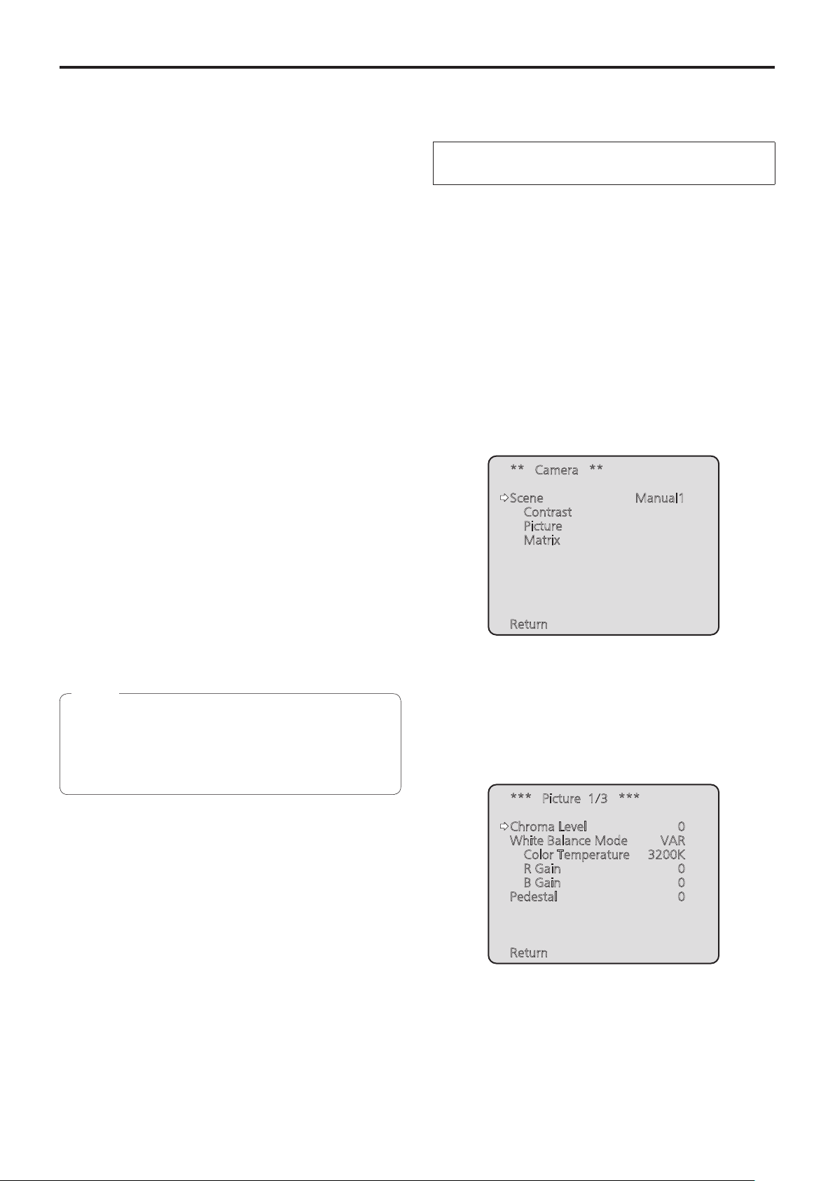
2 Select Manual1, Manual2 or Manual3 as the
shooting mode by following the procedure in
“Selecting the shooting modes (scene files)”
(page 10).
** Camera **
Scene Manual1
Contrast
Picture
Matrix
Return
3 Press the [▲] or [▼] button to bring the cursor
to “Picture”.
4 Press the [
The “Picture 1/3” sub-menu is displayed.
] button.
○
*** Picture 1/3 ***
Chroma Level 0
White Balance Mode VAR
Color Temperature 3200K
R Gain 0
B Gain 0
Pedestal 0
Return
17
Page 18
White balance adjustment
(continued)
5 Press the [▲] or [▼] button to bring the cursor
to “White Balance Mode”.
6 Press the [
“White Balance Mode” starts blinking.
] button.
○
7 Press the [▲] or [▼] button to change the
White Balance Mode to be used to “AWB A” or
“AWB B”, and press the [○] button to enter the
selection.
8 Press the [MENU] button for 2 seconds.
The camera menu display is exited.
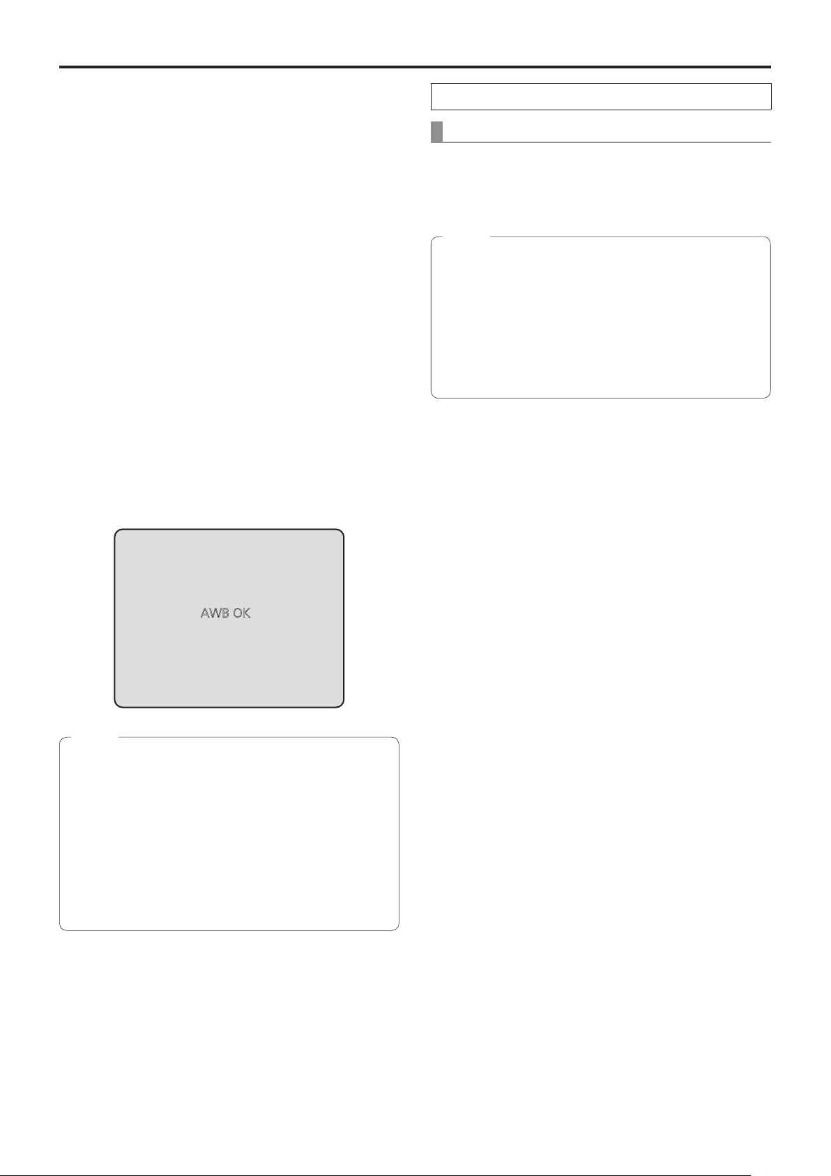
9 Press the [SET] button for 2 seconds.
The auto white balance adjustment (AWB) is performed,
and the white balance setting is entered.
● When the white balance adjustment is completed
successfully, “AWB OK” appears in the center of the
screen.
However, this does not appear when “OSD Status” is
set to “Off” in the camera menu.
When performing the operations using the controller
When using an AW-RP50, AW-RP120 or AK-HRP200:
Refer to the Operating Instructions of the controller.
Notes
● White balance may not be correctly set if the lighting of
the object is too weak.
● Since the unit has a built-in memory, the set white
balance will remain in the memory even if power is
turned off. Therefore, it is not necessary to reset the
white balance if the color temperature of those objects
remains unchanged. However, it must be reset if the
color temperature changes, such as when you move
from indoors to outside, or vice versa.
AWB OK
Notes
● The white balance cannot be adjusted when color bars
are displayed. Press the [MODE] button to switch to the
camera picture.
● When the adjustment has failed, an error message
such as “OUT RANGE NG”, “HIGH LIGHT NG”, “LOW
LIGHT NG”, “ATW NG”, “3200K NG”, “5600K NG” or
“VAR NG” is displayed.
However, this does not appear when “OSD Status” is
set to “Off” in the camera menu.
● In Night mode (page 36, page 38), the white
balance adjustment cannot be used.
18
Page 19

White balance adjustment
(continued)
Auto tracking white adjustment (ATW)
●
When white balance adjustment is set to “ATW”, the white
balance will be corrected automatically, even if the light
source or color temperature changes.
This function works when “ATW” is selected instead of
“AWB A” or “AWB B” by following the steps for “Automatic
adjustment” in “White balance adjustment” (page 17).
Notes
● ATW might not function properly when high brightness
light (ex. fluorescent lamp) beams into a screen.
● White balance may not be accurately set if there is no
white object in the scene being shot.
● The white balance may shift out of adjustment when
a different kind of light source such as sunlight or
fluorescent lighting applies.
● When switching from Night mode to Day mode, the
white balance may shift out of adjustment.
3200K and 5600K presets
●
When “3200K” or “5600K” is selected for the white balance,
the white balance is set using a color temperature of
3200K (equivalent to halogen light) or 5600K (equivalent to
daylight), respectively.
This function works when “3200K” or “5600K” is selected
instead of “AWB A” or “AWB B” in the “Automatic adjustment”
procedure in “White balance adjustment” (page 17).
● From the controller, this operation can only be performed
using the menu displays. See “Basic operations”
(page 22).
Color temperature adjustment (VAR)
●
When “VAR” is selected for the white balance, you can select
a color temperature between 2400K to 9900K.
Note
● The displayed “VAR” value does not guarantee an
absolute value.
Use the value as a reference.
19
Page 20
White balance adjustment
Manual adjustment
●
(R gain and B gain adjustment)
White balance can be adjusted manually.
(continued)
5 Press the [
“White Balance Mode” starts blinking.
] button.
○
Note
● R/B gain adjustments can only be performed when
White Balance Mode is set to “AWB A”, “AWB B” or
“VAR”.
When performing the operations
using the wireless remote control
● Steps
1 through 6 represent the procedure for selecting
the “AWB A”, “AWB B” or “VAR” memory. They need not
be taken if a selection has already been made.
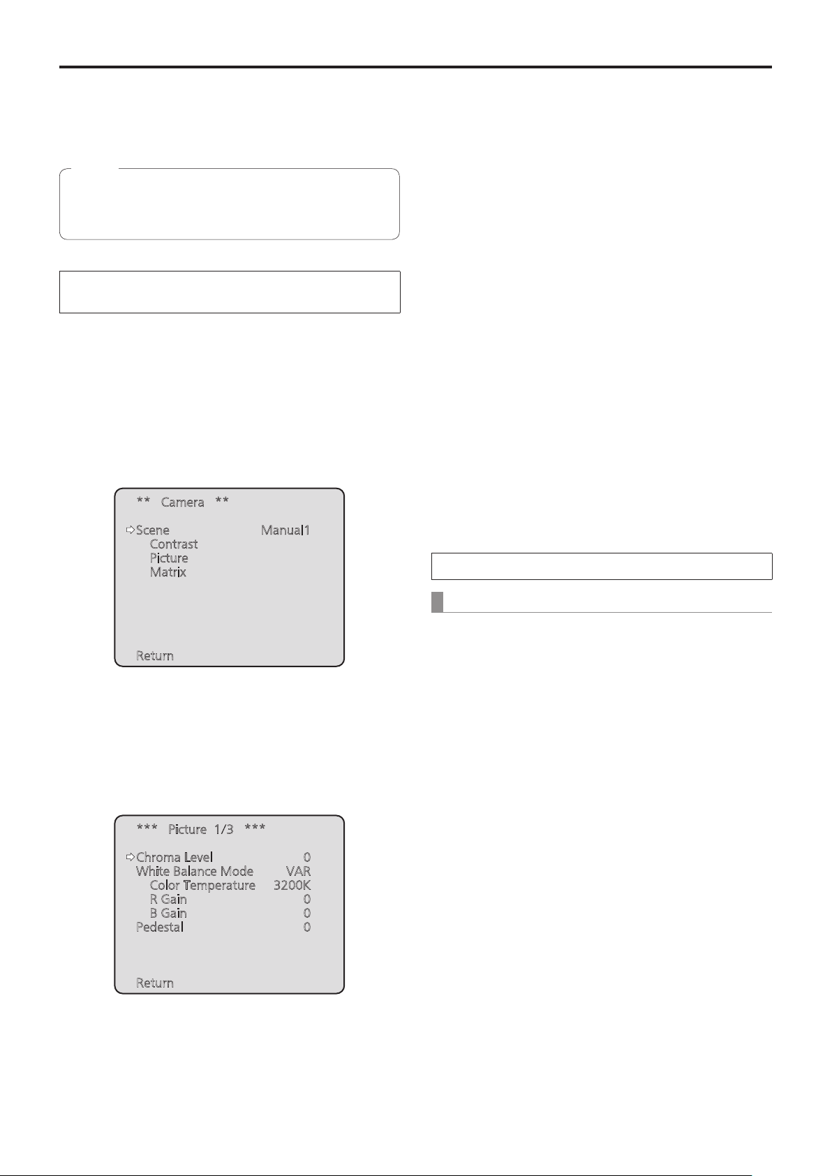
1 Select Manual1, Manual2 or Manual3 as the
shooting mode by following the procedure in
“Selecting the shooting modes (scene files)”
(page 10).
** Camera **
Scene Manual1
Contrast
Picture
Matrix
6 Press the [▲] or [▼] button to change the
White Balance Mode to “AWB A”, “AWB B” or
“VAR”, and press the [○] button to confirm the
selection.
7 Press the [▲] or [▼] button to bring the cursor
to “R Gain” or “B Gain.”
8 Press the [
“B Gain” value blink.
] button to make the “R Gain” or
○
9 Press the [▲] or [▼] button to change the
“R Gain” or “B Gain” numerical value, and
press the [○] button to enter the setting.
When performing the operations using the controller
Return
2 Press the [▲] or [▼] button to bring the cursor
to “Picture”.
3 Press the [
The “Picture 1/3” sub-menu is displayed.
] button.
○
*** Picture 1/3 ***
Chroma Level 0
White Balance Mode VAR
Color Temperature 3200K
R Gain 0
B Gain 0
Pedestal 0
Return
When using an AW-RP50, AW-RP120 or AK-HRP200:
Refer to the Operating Instructions of the controller.
4 Press the [▲] or [▼] button to bring the cursor
to “White Balance Mode”.
20
Page 21
Black level (master pedestal) adjustment
■Black level (master pedestal)
adjustment
The black level can be adjusted when using a multiple
number of cameras including the unit. Ask your dealer to
perform this adjustment.
(Use an oscilloscope or waveform monitor for the
adjustment.)
Adjust the black level in accordance with the units and
devices used.
The black level can be adjusted only when Manual1,
Manual2 or Manual3 is selected as the shooting mode
(scene file).
When performing the operations
using the wireless remote control
1 Press the [M/IRIS] button.
Set the iris to the manual mode.
2 Press the [IRIS –] button.
The lens iris closes until the image is completely black.
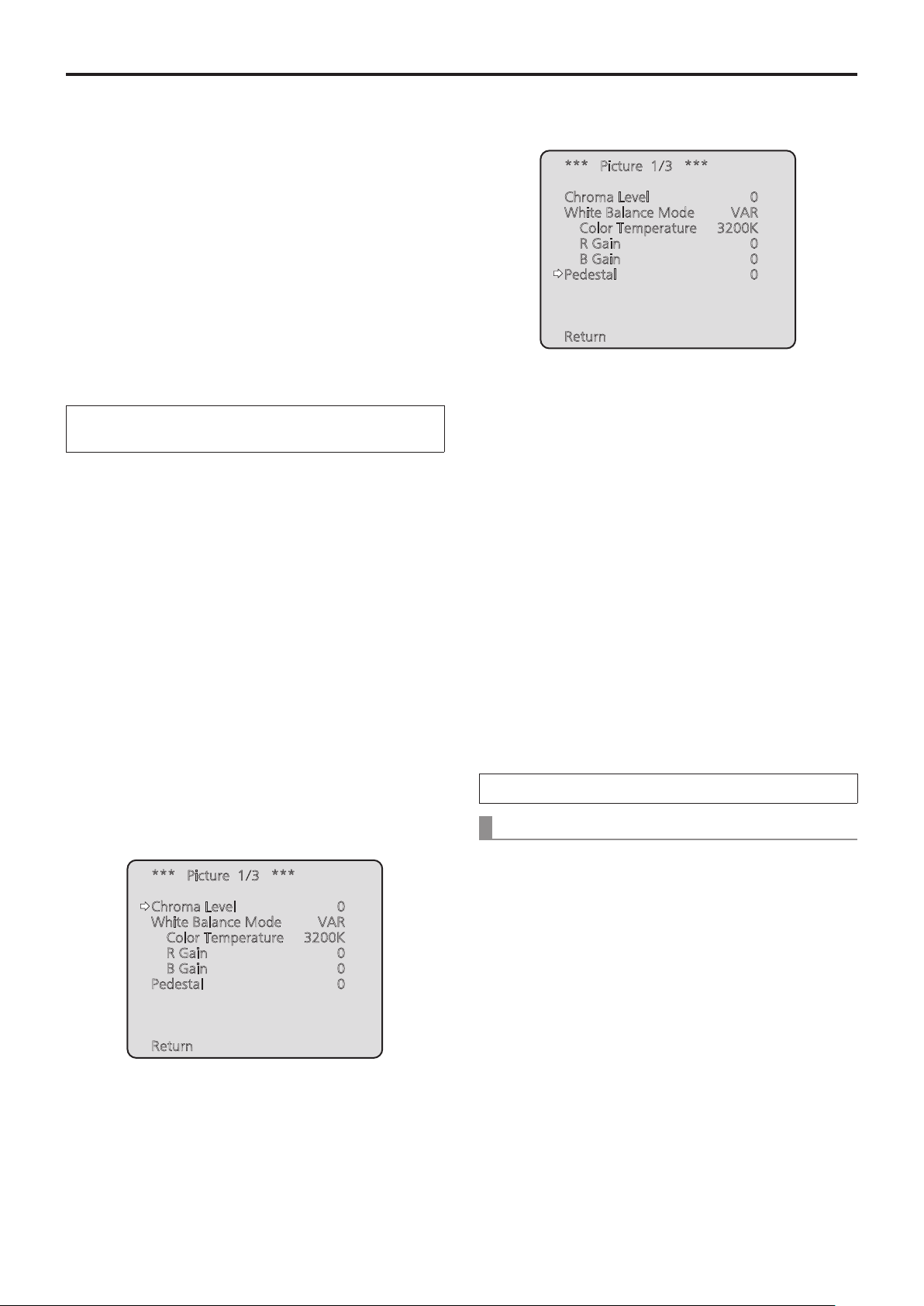
6 Press the [▲] or [▼] button, and bring the
cursor to “Pedestal”.
*** Picture 1/3 ***
Chroma Level 0
White Balance Mode VAR
Color Temperature 3200K
R Gain 0
B Gain 0
Pedestal 0
Return
7 Press the [
value blinking.
] button to start the “Pedestal”
○
8 Press the [▲] or [▼] button, change the
“Pedestal” value, and press the [○] button to
enter the selection.
9 Press the [MENU] button for 2 seconds.
The camera menu display is exited.
3 Select Manual1, Manual2 or Manual3 by
following the procedure in “How to select the
shooting mode” (page 10) under “Selecting the
shooting modes (scene files)”.
4 Press the [▲] or [▼] button to bring the cursor
to “Picture”.
5 Press the [
The “Picture 1/3” sub-menu is displayed.
] button.
○
*** Picture 1/3 ***
Chroma Level 0
White Balance Mode VAR
Color Temperature 3200K
R Gain 0
B Gain 0
Pedestal 0
Return
10
If necessary, press the [A/IRIS] button to adjust
the iris automatically.
When performing the operations using the controller
When using an AW-RP50, AW-RP120 or AK-HRP200:
Refer to the Operating Instructions of the controller.
21
Page 22
Basic operations
Camera menus are displayed on the monitor when the unit’s
settings are to be selected.
The monitor is connected to the video signal output
connector.
The basic camera menu operations involve displaying
sub-menus from the Top Menu items, and selecting settings
on the sub-menus.
Some sub-menus have menu items for performing more
detailed settings.
The camera menu operations are conducted using the
wireless remote control.
If a controller is connected, they can also be conducted using
the controller.
Note
● Check that your controller is the following version.
AW-RP50: Ver 3.10.00 or later
AW-RP120: Ver 2.10.00 or later
AK-HRP200: Ver 4.10-00-0.00 or later
If the version older, an upgrade is required.
For details on upgrading, visit the support page on the
following website.
http://pro-av.panasonic.net/
Only the steps taken using the wireless remote
control will be described here for the operations
conducted to select and set the items.
For details of the operations conducted using the
controller, substitute “controller” for “wireless
remote control” when reading the basic operations.
Also, refer to the Operating Instructions of the
controller.
Described below are the basic operations for changing the
camera menu item settings using the wireless remote control
and controller (AW-RP50, AW-RP120 or AK-HRP200).
Table of operations
Camera menu operation Wireless remote control
Selecting the unit to be
operated
Displaying the Top Menu
Selecting the items
Displaying the
sub-menus
Returning to the
previous menu
Changing the settings
Canceling the setting
change
Press the [CAM1], [CAM2], [CAM3]
or [CAM4] button.
Press the [MENU] button for
2 seconds.
Press the [▲] or [▼] ([◄] or [►])
button.
Press the [
With the cursor at the “Return”
position, press the [
With the cursor at the item to be
changed, press the [
start the item’s value blinking.
Use the [▲], [▼], [◄] and [►]
buttons to change the value, and
press the [○] button to enter the
change.
While the setting is blinking, press
the [MENU] button quickly (for less
than 2 seconds).
] button. Press the F1 dial. Press the SELECT dial.
○
] button.
○
] button to
○
Controller
AW-RP50 AW-RP120 AK-HRP200
1. Press and hold the [SELECT]
button for about 2 seconds.
The camera number in the
camera number display area
blinks.
Press one of the [CAMERA
STATUS/SELECTION] buttons.
Press the [CAMERA OSD] button for
2 seconds.
Turn the F1 dial. Turn the SELECT dial.
With the cursor at the “Return”
position, press the F1 dial.
1. Press the F1 dial to start the
setting blinking.
2. Turn the F1 dial to change the
setting.
3. Press the F1 dial to enter the
setting (and stop the blinking).
— —
2. Press the lit [UP]/[DOWN] button.
Press the lit [UP]/[DOWN]
button to select the camera
number.
3. Press the [SELECT] button.
Control of the selected camera
is enabled.
Press and hold the [CHARA/MENU]
button for about 2 seconds.
With the cursor at the “Return”
position, press the SELECT dial.
1. Press the SELECT dial to start
the setting blinking.
2. Turn the SELECT dial to change
the setting.
3. Press the SELECT dial to
enter the setting (and stop the
blinking).
22
Page 23
Basic operations
(continued)
Camera menu operation Wireless remote control
Exiting the camera menu
operations
Press the [MENU] button for
2 seconds.
AW-RP50 AW-RP120 AK-HRP200
Press the [CAMERA OSD] button for
2 seconds.
Controller
Press and hold the [CHARA/MENU]
button for about 2 seconds.
Notes
● Perform the menu operations and exit from the menus using the controller which displayed the Top Menu.
If a menu operation has been performed or a menu has been exited using another controller, first display the Top Menu
and exit from it using one controller, and then display the Top Menu and exit from it using the other controller.
● The unit uses a different method to operate its menus from the one employed by the convertible cameras and HD
integrated cameras which have already been launched onto the market.
For details, refer to the Operating Instructions of the camera concerned.
● The response speed of the camera differs slightly depending on the controller used.
● Some functions may be limited for the following existing controllers.
Item AW-RP555 AW-RP655
Camera OSD menu operation Supported Supported
Scene
Iris Mode Supported Supported
Shutter Mode
Gain Supported *
ND Filter Not supported Not supported
Day/Night Supported with some restrictions *
White Balance Mode
AWB/ABB Supported Supported
Color Temperature Not supported Not supported
R Gain / B Gain Not supported Supported
Pedestal Not supported Supported
R Pedestal / B Pedestal Not supported Supported with some restrictions *
Detail Not supported Not supported
V Detail Level Not supported Not supported
CAM/BAR Supported *
Pan Supported Supported
Tilt Supported Supported
Preset Supported Supported
Preset Speed Not supported Not supported
Preset Speed Table Not supported Not supported
Preset Scope Not supported Not supported
Freeze During Preset Not supported Not supported
Focus Mode Supported with some restrictions *
Zoom Supported Supported
Digital Extender Not supported Not supported
OIS Not supported Not supported
Tally Supported Supported
Supported with some restrictions *
Supported *
(1/2/3/USER)
(Step only)
Supported *
(AWB A/AWB B/ATW only)
*1 If the setting value is changed on another device, it may take some time for the setting value to be applied.
2
*
If the Shutter Mode is not turned off/on after configuration, the value will not be changed.
3
*
Improper operation will occur when Gain is set to 19 dB or higher.
4
*
If the setting value is changed on another device, the setting value will not be applied.
(If the value is configured locally on the device, the value will be applied.)
5
*
The value range display will be incorrect (–150 to +150).
1
(HALOGEN/FLUORESCENT/OUTDOOR/USER)
2
1
4
1
1
4
Supported with some restrictions *
Supported with some restrictions *
Supported with some restrictions *
Supported
Not supported
Supported
(AWB A/AWB B/ATW only)
Supported
3
4
5
4
23
Page 24

Basic operations
(continued)
■When performing the
operations using the wireless
remote control
1 Press the [CAM1], [CAM2], [CAM3] or [CAM4]
button to select the unit which is to be
operated.
2 Press the [MENU] button for 2 seconds.
The Top Menu is displayed.
3 Press the [▲] or [▼] button to bring the cursor
to the item to be selected.
Each time the [▲] or [▼] button is pressed, the cursor
moves.
The cursor can be moved in the same way using the [◄]
and [►] buttons.
4 Press the [
The sub-menu of the selected item is displayed.
(Some sub-menu items have a sub-menu of their own.)
] button.
○
8 Press the [
The value of the item to be set is entered, and it stops
blinking.
] button.
○
9 After the setting has been completed, press the
[MENU] button for 2 seconds.
The camera menu display is exited.
5 Press the [▲] or [▼] button to bring the cursor
to the item to be set.
Each time the [▲] or [▼] button is pressed, the cursor
moves.
The cursor can be moved in the same way using the [◄]
and [►] buttons.
With the cursor at the “Return” position, press the [
button to return to the previous menu.
6 Press the [
The value of the item to be set starts blinking.
] button.
○
○
]
7 Press the [▲] or [▼] button to change the
setting.
The setting can be changed in the same way using the
[◄] and [►] buttons.
24
Page 25
Basic operations
(continued)
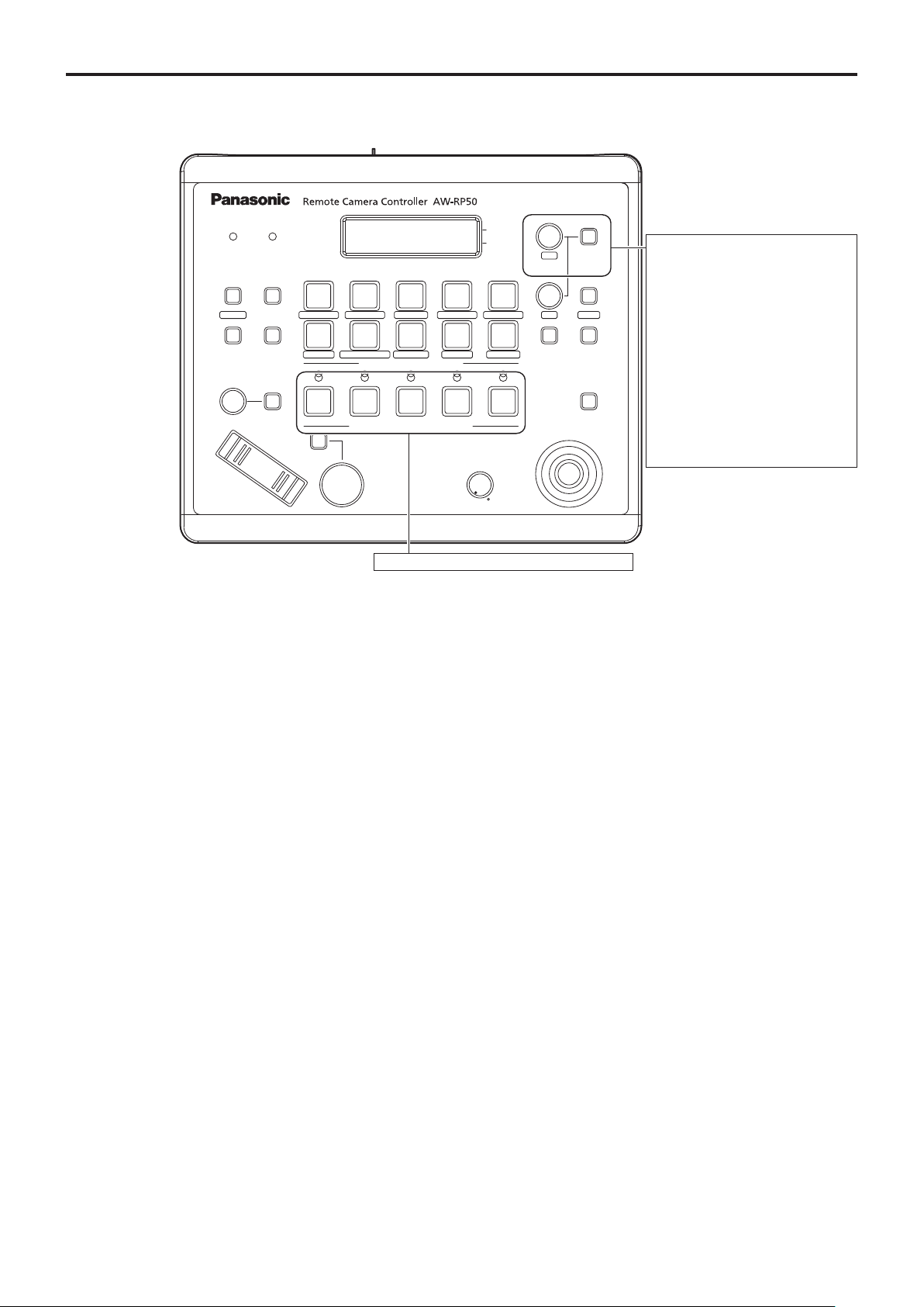
■Operations on the AW-RP50 Remote Camera Controller
F1
POWER ALARM F1 CAMERA
1 2 3
R/B GAIN R/B PED
6 7 8 9 10
DETAIL
SCENE/MODE
PRESET MEMORY / MENU
1 2 3 4 5
CAMERA STATUS / SELECTION
AUTO
AWB/ABB4SHUTTER
TELE
GAIN/PED
PAGEMENU F2 EXIT
DELETESTORE
ZOOM
WIDE
F2
OSD
5
SYSTEMSETUPCAMERA
PTZ/FOCUS SPEEDFOCUS/PUSH OAF
HILOW
USER2USER1
PT ACTIVEAUTOIRIS
For operating the camera menus.
CAMERA OSD:
When this is pressed for 2
seconds, the selected camera
menu is displayed, overlapping
the camera output image. When
it is pressed for 2 seconds while
a camera menu is displayed, the
menu is exited.
F1:
Turn F1 to move the cursor up and
down in the camera menu or to
change setting values. Press F1 to
move to the next level of a menu
item or to change a setting value
at the lowest level.
For selecting the cameras to be operated.
Camera menu operation
●
1 Press the appropriate [CAMERA STATUS/
SELECTION] button to select the unit you want
to operate.
2 Press and hold the [CAMERA OSD] button on
the AW-RP50 for about 2 seconds.
The AW-HE40 camera menu appears on the monitor.
3 Turn the F1 dial to select an AW-HE40 camera
menu item or to change a setting value.
Turn the F1 dial to move the cursor up and down or to
change setting values.
Press the F1 dial to move to the next level of a menu
item or to change a setting value at the lowest level.
4 To exit the camera menu, press and hold the
[CAMERA OSD] button for about 2 seconds.
Switching between Day and Night mode
●
1 Press the [MENU] button on the AW-RP50.
The [MENU] button lights, and the [PRESET MEMORY/
MENU] buttons become selectable.
2 Press the [9 (SETUP)] button in the [PRESET
MEMORY/MENU] area.
The button lights, and the SETUP menu appears on the
LCD panel.
3 Turn the F1 dial to select “FUNCTION”, then
press the F1 dial.
4 Turn the F1 dial to select “OPTION”.
“Off” or “On” appears on the bottom right (F2 area) of the
LCD panel.
5 Turn the F2 dial to select “Off” or “On”, then
press the F2 dial.
Off: Day mode
On: Night mode
● Auto mode cannot be specified with this operation.
25
Page 26

Basic operations
Color temperature setting (COLOR
●
TEMP)
(continued)
Preset speed table setting (PRESET
●
SPEED)
1 Press the [MENU] button on the AW-RP50.
The [MENU] button lights, and the [PRESET MEMORY/
MENU] buttons become selectable.
2 Press the [4 (AWB/ABB)] button in the [PRESET
MEMORY/MENU] area.
The button lights, and the AWB/ABB menu appears on
the LCD panel.
3 Turn the F1 dial to select “VAR”.
Color temperature configuration is enabled when “VAR”
is selected, and it is initially set to the color temperature
held on the camera.
To adjust the setting, proceed to the following.
4 Press the [8 (CAMERA)] button in the [PRESET
MEMORY/MENU] area.
The button lights, and the GROUP menu appears on the
LCD panel.
5 Turn the F1 dial to select “COLOR TEMP”, then
press the F1 dial.
The color temperature appears on the bottom right (F2
area) of the LCD panel.
1 Press the [MENU] button on the AW-RP50.
The [MENU] button lights, and the [PRESET MEMORY/
MENU] buttons become selectable.
2 Press the [9 (SETUP)] button in the [PRESET
MEMORY/MENU] area.
The button lights, and the SETUP menu appears on the
LCD panel.
3 Turn the F1 dial to select “PRESET”, then press
the F1 dial.
4 Turn the F1 dial to select “PRESET SPEED”,
then press the F1 dial.
“Slow” or “Fast” appears on the bottom right (F2 area) of
the LCD panel.
5 Turn the F2 dial to select “Slow” or “Fast”, then
press the F2 dial.
6 Turn the F2 dial to select the color temperature,
then press the F2 dial.
26
Page 27

Basic operations
Freezing images during preset playback
●
(FREEZE DURING)
(continued)
Digital image stabilization function
●
setting
1 Press the [MENU] button on the AW-RP50.
The [MENU] button lights, and the [PRESET MEMORY/
MENU] buttons become selectable.
2 Press the [9 (SETUP)] button in the [PRESET
MEMORY/MENU] area.
The button lights, and the SETUP menu appears on the
LCD panel.
3 Turn the F1 dial to select “FUNCTION”, then
press the F1 dial.
4 Turn the F1 dial to select “FREEZE DURING”,
then press the F1 dial.
“Off” or “On” appears on the bottom right (F2 area) of the
LCD panel.
5 Turn the F2 dial to select “Off” or “On”, then
press the F2 dial.
Off: Do not freeze the current preset playback images.
On: Freeze the current preset playback images.
1 Press the [MENU] button on the AW-RP50.
The [MENU] button lights, and the [PRESET MEMORY/
MENU] buttons become selectable.
2 Press the [9 (SETUP)] button in the [PRESET
MEMORY/MENU] area.
The button lights, and the SETUP menu appears on the
LCD panel.
3 Turn the F1 dial to select “FUNCTION”, then
press the F1 dial.
4 Turn the F1 dial to select “I.S.”, then press the
F1 dial.
“Off” or “On” appears on the bottom right (F2 area) of the
LCD panel.
5 Turn the F2 dial to select “Off” or “On”, then
press the F2 dial.
Off: Turn the digital image stabilization function off.
On: Turn the digital image stabilization function on.
27
Page 28

Basic operations
Digital extender (D.EXTENDER) function
●
(continued)
setting
1 Press the [MENU] button on the AW-RP50.
The [MENU] button lights, and the [PRESET MEMORY/
MENU] buttons become selectable.
Assigning [FREEZE DURING], [COLOR
●
TEMP] and [DIGITAL EXTENDER] to the
[USER] buttons
You can assign the on/off functions for freezing images
during preset playback (FREEZE DURING), color
temperature settings (COLOR TEMP) and digital extender
function (DIGITAL EXTENDER) to the [USER] buttons.
2 Press the [9 (SETUP)] button in the [PRESET
MEMORY/MENU] area.
The button lights, and the SETUP menu appears on the
LCD panel.
3 Turn the F1 dial to select “FUNCTION”, then
press the F1 dial.
4 Turn the F1 dial to select “D. EXTENDER”, then
press the F1 dial.
“Off” or “On” appears on the bottom right (F2 area) of the
LCD panel.
5 Turn the F2 dial to select “Off” or “On”, then
press the F2 dial.
Off: Turn the digital extender function off.
On: Turn the digital extender function on.
1 Press the [MENU] button on the AW-RP50.
The [MENU] button lights, and the [PRESET MEMORY/
MENU] buttons become selectable.
2 Press the [9 (SETUP)] button in the [PRESET
MEMORY/MENU] area.
The button lights, and the SETUP menu appears on the
LCD panel.
3 Turn the F1 dial to select “USER1” or “USER2”,
then press the F1 dial.
The functions that can be assigned to the [USER] button
appear on the bottom right (F2 area) of the LCD panel.
4 Turn the F2 dial to select “FREEZE DURING”,
“COLOR TEMP” or “D.EXT” then press the F2
dial.
FREEZE DURING:
Function that freezes the current preset playback
images.
COLOR TEMP:
Color temperature settings
D. EXT:
Digital extender function
28
Page 29
Basic operations
(continued)
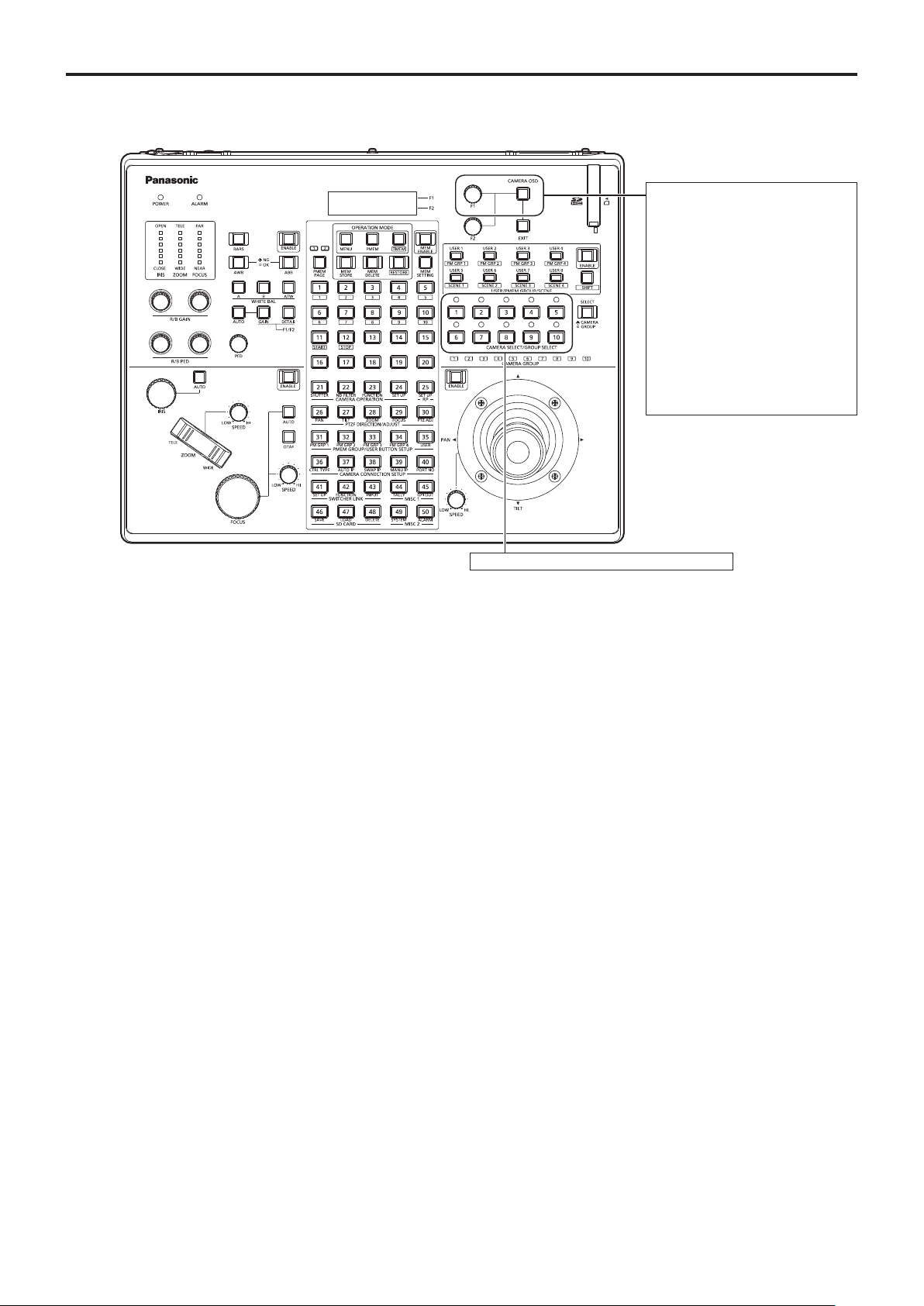
■Operations on the AW-RP120 Remote Camera Controller
For operating the camera menus.
CAMERA OSD:
When this is pressed for 2
F1:
Turn F1 to move the cursor up and
seconds, the selected camera
menu is displayed, overlapping
the camera output image. When
it is pressed for 2 seconds while
a camera menu is displayed, the
menu is exited.
down in the camera menu or to
change setting values. Press F1 to
move to the next level of a menu
item or to change a setting value
at the lowest level.
Camera menu operation
●
1 Press the appropriate [CAMERA SELECT/
GROUP SELECT] button ([1] to [10]) to select
the unit you want to operate.
2 Press and hold the [CAMERA OSD] button on
the AW-RP120 for about 2 seconds.
The AW-HE40 camera menu appears on the monitor.
3 Turn the F1 dial to select an AW-HE40 camera
menu item or to change a setting value.
Turn the F1 dial to move the cursor up and down or to
change setting values.
Press the F1 dial to move to the next level of a menu
item or to change a setting value at the lowest level.
4 To exit the camera menu, press and hold the
[CAMERA OSD] button for about 2 seconds.
For selecting the cameras to be operated.
Switching between Day and Night mode
●
1 Press the [MENU] button on the AW-RP120.
The [MENU] button lights.
2 Press the FUNCTION menu [23] button.
The button lights, and the OPTION menu appears on the
LCD panel.
3 Turn the F1 dial to select “FUNCTION”, then
press the F1 dial.
4 Turn the F1 dial to select “OPTION”.
“Off” or “On” appears on the bottom right (F2 area) of the
LCD panel.
5 Turn the F2 dial to select “Off” or “On”, then
press the F2 dial.
Off: Day mode
On: Night mode
● Auto mode cannot be specified with this operation.
29
Page 30

Basic operations
Color temperature setting (COLOR
●
(continued)
TEMP)
Freezing images during preset playback
●
(FREEZE DURING)
1 Press the [EXIT] button and the [ATW] button of
[WHITE BAL] simultaneously.
The [A], [B], and [ATW] buttons of [WHITE BAL] light,
and color temperature setting mode is enabled.
The color temperature setting value appears on the LCD
screen during this time.
2 Turn the F1 dial to change the color
temperature.
Press the [A], [B], and [ATW] buttons of [WHITE BAL] to
return to the mode of the selected button.
The mode will switch from the color temperature mode to
the original mode after a specific amount of time passes.
To configure the color temperature setting again, press
the [EXIT] button and the [ATW] button of [WHITE BAL]
simultaneously.
Preset speed table setting (PRESET
●
SPEED)
1 Press the [MENU] button on the AW-RP120.
The [MENU] button lights.
2 Press the FUNCTION menu [23] button.
The button lights, and the OPTION menu appears on the
LCD panel.
3 Turn the F1 dial to select “PRESET SPEED”,
then press the F1 dial.
“Slow” or “Fast” appears on the bottom right (F2 area) of
the LCD panel.
4 Turn the F2 dial to select “Slow” or “Fast”, then
press the F2 dial.
1 Press the [MENU] button on the AW-RP120.
The [MENU] button lights.
2 Press the FUNCTION menu [23] button.
The button lights, and the OPTION menu appears on the
LCD panel.
3 Turn the F1 dial to select “FREEZE DURING”,
then press the F1 dial.
“Off” or “On” appears on the bottom right (F2 area) of the
LCD panel.
4 Turn the F2 dial to select “Off” or “On”, then
press the F2 dial.
Off: Do not freeze the current preset playback images.
On: Freeze the current preset playback images.
Digital image stabilization function
●
setting
1 Press the [MENU] button on the AW-RP120.
The [MENU] button lights.
2 Press the FUNCTION menu [23] button.
The button lights, and the OPTION menu appears on the
LCD panel.
3 Turn the F1 dial to select “I.S.”, then press the
F1 dial.
“Off” or “On” appears on the bottom right (F2 area) of the
LCD panel.
30
4 Turn the F2 dial to select “Off” or “On”, then
press the F2 dial.
Off: Turn the digital image stabilization function off.
On: Turn the digital image stabilization function on.
Page 31

Basic operations
Digital extender (D.EXTENDER) function
●
(continued)
setting
1 Press the [MENU] button on the AW-RP120.
The [MENU] button lights.
2 Press the FUNCTION menu [23] button.
The button lights, and the OPTION menu appears on the
LCD panel.
Assigning [FREEZE DURING], [COLOR
●
TEMP] and [DIGITAL EXTENDER] to the
[USER] buttons
You can assign the on/off functions for freezing images
during preset playback (FREEZE DURING), color
temperature settings (COLOR TEMP) and digital extender
function (DIGITAL EXTENDER) to the [USER] buttons.
1 Press the [MENU] button on the AW-RP120.
The [MENU] button lights.
3 Turn the F1 dial to select “D. EXTENDER”, then
press the F1 dial.
“Off” or “On” appears on the bottom right (F2 area) of the
LCD panel.
4 Turn the F2 dial to select “Off” or “On”, then
press the F2 dial.
Off: Turn the digital extender function off.
On: Turn the digital extender function on.
2 Press the USER menu [35] button.
The button lights, and the USER1 menu appears on the
LCD panel.
3 Turn the F1 dial to select “USER1” to “USER8”,
then press the F1 dial.
The functions that can be assigned to the [USER] button
appear on the bottom right (F2 area) of the LCD panel.
4 Turn the F2 dial to select “FREEZE DURING”,
“COLOR TEMP” or “D.EXT” then press the F2
dial.
FREEZE DURING:
Function that freezes the current preset playback
images.
COLOR TEMP:
Color temperature settings
D. EXT:
Digital extender function
31
Page 32

Basic operations
(continued)
■Operations on the AK-HRP200 Remote Operation Panel
For operating the camera menus.
When the [CHARA/MENU] button is pressed
for 2 seconds, the selected camera menu
is displayed, overlapping the camera output
image. When it is pressed for 2 seconds while
a camera menu is displayed, the menu is
exited.
SELECT:
Turn SELECT to move the cursor up and
down in the camera menu or to change
setting values. Press SELECT to move to
the next level of a menu item or to change a
setting value at the lowest level.
Camera menu operation
●
HEAD
POWER
SHIFT
UP
DATA
SET
DOWN
SET UP
SHIFT
+
UP+DOWN
CHARA
MENU
SELECT
POWER
SCENE 1
VR LOCK
DTL
ND
ND/CC M.GAIN/M.PED
SAVE/LOAD
TALLY/CALL
ALM OPT
EXT
D.EXT
CLOSE
VF
SKINDTLMATRIX5600K
SCENE/USER FILE
SCENE 2
USER 2USER 1
CC SHT SYNC
M.GAIN
DISPLAY SELECT
SENSE
COARSEAUTO
BARS
WHITE
TEST
KNEE
OFF
SCENE 3
USER 3
FLARE/PED
M.PED 10-19
IRIS
SHUTTER
EXECUTEEXIT
IRIS/M.PED LOCK IRIS
OPENCLOSE
FULL
AUTO
BLACK
SET UP
DTL
SHUTTER
OFF
ON
STEP/SYNC
SCENE 4
STORE
GAIN
CAMERA
No.
SELECT
M.PED
PUSH
PREVIEW
For selecting the cameras to be operated.
1. Press and hold the [SELECT] button for
about 2 seconds.
The camera number in the camera number
display area blinks.
2. Press the lit [UP]/[DOWN] button.
Press the lit [UP]/[DOWN] button to select
the camera number.
3. Press the [SELECT] button.
Control of the selected camera is enabled.
1 Press and hold the [CHARA/MENU] button on
the AK-HRP200 for about 2 seconds.
The AW-HE40 camera menu appears on the monitor.
2 Turn the SELECT dial to select an AW-HE40
camera menu item or to change a setting value.
Turn the SELECT dial to move the cursor up and down
or to change setting values.
Press the SELECT dial to move to the next level of a
menu item or to change a setting value at the lowest
level.
3 To exit the camera menu, press and hold the
[CHARA/MENU] button for about 2 seconds.
32
Page 33

Basic operations
(continued)
The following operations can be performed from the AK-HRP200 Remote Operation Panel.
For details on operations, refer to the AK-HRP200 Operating Instructions <Basics>.
AW-HE40
: Supported
Control/display component Label
1 Camera power switch HEAD POWER
2 Viewfinder power switch VF POWER —
3 Color bar signal output switch BARS/TEST
4 Auto white balance switch AUTO WHITE
5 Auto black balance switch AUTO BLACK
6 Auto setup switch AUTO SETUP —
7 5600k switch 5600k —
8 Matrix switch MATRIX —
9 Skin color detail switch SKIN DTL ON —
10 Knee OFF switch KNEE OFF —
11 Detail OFF switch DTL OFF —
Shutter ON/OFF switch, STEP/SYNC
12
switch
13 Scene / user file selection switch SCENE/USER FILE SHIFT —
14 Scene / user file 1 switch SCENE/USER FILE1
15 Scene / user file 2 switch SCENE/USER FILE2
16 Scene / user file 3 switch SCENE/USER FILE3
17 Scene file 4 switch SCENE FILE 4
18 Scene / user file storage switch SCENE/USER FILE STORE —
19 Volume lock switch VOL LOCK
20 R gain volume GAIN R
21 B gain volume GAIN B
22 R flare / pedestal volume FLARE/PED —
23 B flare / pedestal volume FLARE/PED —
24 DTL volume DTL —
25 Data set (up) DATA SET UP
26 Data set (down) DATA SET DOWN
27 Adjustment value display None
28 IRIS display IRIS
29 ND/CC display selection switch
30 ND display ND —
31 CC display CC —
M.GAIN / M.PED display DISPLAY SELECT
32
Selection switch M.GAIN/M.PED
33 M.GAIN display M.GAIN
34 M.PED display M.PED
SHUTTER display selection DISPLAY SELECT
35
Switch SHUTTER
SHUTTER ON STEP/SYNC
DISPLAY SELECT
ND/CC
: Supported with some
restrictions
—: Not supported
Remarks
Does not transition to TEST_ON.
Running state after accepting AWB/
ABB lasts at least 2 sec.
The shutter value is fixed during
transition from SYNC. (See No. 36)
Equivalent to Manual1.
Equivalent to Manual2.
Equivalent to Manual3.
Equivalent to Full Auto
Operation is supported, but the IRIS
value cannot be displayed.
Used for ZOOM / FOCUS MODE
switching.
33
Page 34

Basic operations
Control/display component Label
36 SHUTTER display SHT
37 SYNC display SYNC
38 Camera number display CAM No.
39 Camera number tens display 10-19
40 Camera selection switch CAM SEL
41 Menu / character switch
42 Rotary selection switch SELECT
43 Red/green tally display, call switch TALLY/CALL
44 Alarm display ALARM —
45 Optical alarm display OPT —
46 Iris / master pedestal lock IRIS/M.PED LOCK
47 Iris lever
48 Master pedestal volume
49 Preview switch PUSH PREVIEW —
50 Fader full switch FADER FULL —
51 Auto iris switch AUTO
52 Iris close switch CLOSE —
53 Sense volume SENSE
54 Coarse volume COARSE —
55 Lens extender display EXT —
56 Digital extender display D.EXT
57 SD card access display SD CARD
58 Zoom
59 Focus
(continued)
AW-HE40
: Supported
: Supported with some
restrictions
—: Not supported
CHARA
MENU ON/OFF
IRIS ()
M.PED ()
Remarks
The shutter value is fixed during
transition from SYNC.
• For 59.94p, 59.94i: 1/100
• For 29.97p: 1/100
• For 50p, 50i: 1/120
• For 25p: 1/120
The display for 7SEG will be “----”
during SYNC.
When ZOOM is selected during
MENU OFF, ZOOM adjustment is
possible using the [UP] and [DOWN]
buttons.
When FOCUS is selected during
MENU OFF, FOCUS adjustment is
possible using the [UP] and [DOWN]
buttons.
CALL is disabled.
The IRIS value cannot be displayed
for 7SEG.
Used for ZOOM/FOCUS SPEED
adjustment.
The indicator lights when the Zoom
Mode is set to “D.Extender”.
When ZOOM is selected, ZOOM
adjustment is possible using the
[UP] and [DOWN] buttons.
When FOCUS is selected, FOCUS
adjustment is possible using the
[UP] and [DOWN] buttons.
34
Page 35

Camera menu items
■Setting the camera menu items
When the unit’s settings are to be selected, the camera
menus are displayed on the monitor.
The monitor is connected to the video signal output
connector.
The basic camera menu operations involve displaying
sub-menus from the Top Menu items, and selecting settings
on the sub-menus.
Some sub-menus have menu items for performing more
detailed settings.
For details on the basic operations to display the camera
menus and change the items using the wireless remote
control or controller (AW-RP50, AW-RP120 or AK-HRP200),
refer to pages 22 to 34.
The “*” and “#” marks in the menu titles indicate the
hierarchical level of the menu currently displayed.
For instance, “* Top Menu *” indicates the first
hierarchical level whereas “** Camera **” and
“## Maintenance ##” indicate that the second hierarchical
level is now displayed.
Menu items accompanied by a “*” mark indicate data
which is stored on a scene by scene basis; menu items
accompanied by a “#” mark indicate data which is stored
together for one camera regardless of the scenes.
■Top Menu screen
* Top Menu *
Camera Scene: Full Auto
System
Maintenance
Camera
Select this to open the camera menu relating to the
camera images.
System
Display the System menu in which the camera’s output
image settings are configured.
Maintenance
Display the Maintenance menu which concerns checking
the unit’s firmware versions, checking the IP address and
initialize the settings.
Note
● The Top Menu does not have a “Return” setting.
To close the menu screen, use the controller to perform
the operation to close the menu screen.
For details, refer to pages 22 to 32.
35
Page 36

Camera menu items
(continued)
■Camera screen
(when Full Auto is selected)
This menu is used for the camera image settings.
** Camera **
Scene Full Auto
Contrast Level 0
Day/Night Day
Night-Day Level ----
Return
Scene
[Full Auto, Manual1, Manual2, Manual3]
Selected here is the shooting mode that matches the
shooting situation.
Select the mode which best suits the prevailing shooting
conditions and the user’s preferences.
Full Auto: In this mode, the optimum settings and
adjustments for the shooting conditions at
hand are automatically established.
When “Full Auto” has been selected, the
detailed setting and adjustment menus are
not displayed.
Manual1 to 3: In these modes, the detailed settings and
adjustments are established manually to
match the prevailing shooting conditions
and the user’s preferences.
When the Manual1, Manual2 or Manual3
mode has been selected, the detailed
setting and adjustment menu for the mode
concerned is displayed.
Contrast Level [–10 to +10]
Set here is the contrast level when the image brightness
is adjusted.
■Camera screen
(when Manual1 to 3 is selected)
** Camera **
Scene Manual1
Contrast
Picture
Matrix
Return
Scene
[Full Auto, Manual1, Manual2, Manual3]
Refer to section on Scene in the column on the left.
Contrast
Select this to display the Contrast screen to adjust the
brightness.
Picture
This menu item displays the Picture screen on which to
adjust the picture quality.
Three screens (Picture 1/3, Picture 2/3 and Picture 3/3)
are provided for the picture quality adjustment menu.
Matrix
This menu item is used to adjust the 16-axis color matrix.
Return
Use this to return to the previous menu.
Day/Night [Day, Night, Auto]
This is used to select normal shooting or low light shooting
(by exposing the subjects to infrared rays).
For details, see “Contrast 2/2 screen” (page 38).
Night-Day Level [Low, Mid, High]
Adjust the level used while switching from Night mode to
Day mode when Day/Night is set to “Auto”.
● This can only be configured when Day/Night is set to
“Auto”.
Return
Use this to return to the previous menu.
36
Page 37

Camera menu items
(continued)
■Contrast 1/2 screen
*** Contrast 1/2 ***
Contrast Mode Auto
Contrast Level 0
Shutter Mode --- Step/Synchro --- Frame Mix --- Auto F.Mix Max Gain 0dB
Gain Auto
AGC Max Gain 24dB
Return
Contrast Mode [Auto, Manual]
This item is used to select whether the image brightness
(contrast) is to be controlled automatically or manually.
Auto: The iris, shutter speed and frame addition
are controlled and the camera brightness is
adjusted automatically.
Manual: Operations are performed using the manually
set values.
Contrast Level [–10 to +10]
Set here is the contrast level when the image brightness
is adjusted.
This item can be set when “Auto” has been selected as
the “Contrast Mode” setting.
Frame Mix [Auto, Off, 6dB, 12dB, 18dB, 24dB]
Select for frame addition (gain-up using sensor storage)
amount.
This item can be set when “Off” is selected as the “Shutter
Mode” item setting.
When frame addition is performed, it will appear as if the
images are missing some frames.
Auto F.Mix Max Gain [0dB, 6dB, 12dB, 18dB]
When “Auto” for the “Contrast Mode” or “Auto” for the
“Frame Mix” is selected, the maximum frame addition
amount can be set.
If frame addition is performed at the Auto setting, it will
appear as if the images are missing some frames.
Gain
[Auto, 0dB, 3dB, 6dB, 9dB, 12dB, 15dB, 18dB,
21dB, 24dB, 27dB, 30dB, 33dB, 36dB, 39dB,
42dB, 45dB, 48dB]
The image gain is adjusted here.
In locations which are too dark, adjust the gain upward;
conversely, in locations which are too bright, adjust it
downward.
When “Auto” is set, the light quantity is adjusted
automatically.
The noise increases when the gain is increased.
Shutter Mode [Off, Step, Synchro]
Select for camera shutter mode.
This item can be set when “Manual” has been selected as
the “Contrast Mode” setting.
Off: The shutter is set to OFF (so that it cannot be
tripped).
Step: The step shutter is set (the steps can be
changed).
Synchro: The synchro shutter is set (the setting can be
changed continuously).
Step/Synchro
This is used to adjust the shutter speed in the mode which
was selected as the “Shutter Mode” setting.
When a higher shutter speed is selected, fast-moving
subjects do not become blurred easily but the images will
be darker.
The shutter speeds that can be set are listed below.
[When 59.94 Hz has been set as the unit’s frequency]
When “Step” is selected as
the “Shutter Mode”
1/100, 1/250, 1/500, 1/1000,
1/2000, 1/4000, 1/10000
When “Synchro” is selected
as the “Shutter Mode”
59.94 Hz to max. 660.09 Hz
(255 steps)
AGC Max Gain
[6dB, 12dB, 18dB, 24dB, 30dB, 36dB, 42dB,
48dB]
When “Auto” is selected as the “Gain” setting, the
maximum gain-up amount can be set.
Return
Use this to return to the previous menu.
[When 50 Hz has been set as the unit’s frequency]
When “Step” is selected as
the “Shutter Mode”
1/120, 1/250, 1/500, 1/1000,
1/2000, 1/4000, 1/10000
When “Synchro” is selected
as the “Shutter Mode”
50.00 Hz to max. 570.12 Hz
(255 steps)
37
Page 38

Camera menu items
(continued)
■Contrast 2/2 screen
*** Contrast 2/2 ***
Day/Night Day
Night-Day Level ----
Return
Day/Night [Day, Night, Auto]
This is used to select normal shooting or low light shooting
(by exposing the subjects to infrared rays).
Day: Normal shooting
Night: Low light shooting
Auto: Automatically switch between standard shooting
and night-vision shooting depending on the
lighting conditions of the subject and shooting
location.
Notes
● In Night mode, Black-and-white images are output.
The lens iris is forcibly set to open.
● In Night mode, the white balance adjustment cannot
be used.
● When focus is set to manual, the focus may shift
when switching between Day and Night mode,
depending on the shooting conditions. If necessary,
either adjust the focus or set the focus to auto.
● Even when “Auto” is selected, shooting may not
switch between day and Night mode as expected,
depending on the subject.
In such cases, perform the following adjustments.
Switching from Day mode to Night mode
Switch when the gain value and frame storage
value are at their maximum due to brightness
adjustment.
When the shooting mode (Scene) is “Manual1”
to “Manual3”, you can adjust the AGC Max Gain
and Auto F.Mix Max Gain settings.
Switching from Night mode to Day mode
You can adjust with the Night-Day Level setting.
If you perform a close-up on a black object, the unit
may switch to Night mode, even after performing the
above adjustments.
Night-Day Level [Low, Mid, High]
Adjust the level used while switching from Night mode to
Day mode when Day/Night is set to “Auto”.
● This can only be configured when Day/Night is set to
“Auto”.
Return
Use this to return to the previous menu.
38
Page 39

Camera menu items
(continued)
■Picture 1/3 screen
*** Picture 1/3 ***
Chroma Level 0
White Balance Mode AWB A
Color Temperature --- R Gain 0
B Gain 0
Pedestal 0
Return
Chroma Level [–3 to +3]
Set here is the color intensity (chroma level) of the
images.
White Balance Mode
[ATW, AWB A, AWB B, 3200K, 5600K, VAR]
The white balance mode is selected here.
Select the mode when the coloring is not natural because
of the nature of the light source or other factors.
If the white color serving as the reference can be
recognized, subjects can be shot with natural coloring.
ATW: This mode automatically corrects the white balance,
even if the light source or color temperature
changes.
AWB A, AWB B:
When AWB A or AWB B is selected and the
white balance is executed, the adjustment results
obtained are stored in the memory selected.
When AWB A or AWB B is then selected, the white
balance stored in the selected memory can be
recalled.
3200K:
This white balance mode is ideal when a 3200K
halogen light is used as the light source.
5600K:
This white balance mode is ideal when 5600K
sunlight or fluorescent lighting is used as the light
source.
VAR: Specify a color temperature from 2400K to 9900K.
R Gain, B Gain [–30 to +30]
When “AWB A”, “AWB B” or “VAR” is selected as the White
Balance Mode setting, the white balance can be finely
adjusted after automatic white balance (AWB) has been
performed.
Notes
● When automatic white balance (AWB) is executed,
the R Gain and B Gain values are returned to “0”.
● When “AWB A”, “AWB B” or “VAR” is selected as
the White Balance Mode setting, the R Gain and
B Gain adjustment values can be stored in the three
memories, A, B and VAR.
● When new values are set, the previous values are
erased.
Use each of the memories for a different purpose in
accordance with the shooting conditions.
● R Gain and B Gain adjustments cannot be
performed when White Balance Mode is set to
“ATW”, “3200K”, or “5600K”.
Pedestal [–10 to +10]
This item is used to adjust the black level (adjust the
pedestal) so that the dark parts of the images are easier
to see.
These parts become darker when a negative setting is
selected and, conversely, lighter when a positive setting is
selected.
Return
Use this to return to the previous menu.
Color Temperature [2400K to 9900K]
Specify a color temperature from 2400K to 9900K (in
increments of about 100K).
This is enabled when White Balance Mode is set to “VAR”.
39
Page 40

Camera menu items
(continued)
■Picture 2/3 screen
*** Picture 2/3 ***
Detail Low
Detail Level H 18
Detail Level L 9
Flesh Tone Mode Off
HDR Off
DRS Off
Gamma Type Normal
Gamma Level Mid
Return
Detail [Off, Low, High]
The image detail (image sharpness) is adjusted here.
When “Low” or “High” is selected, the detail is enhanced.
Detail Level H
[Detail Level L setting +1 to 18]
The image sharpness level is adjusted here when “High”
has been selected as the “Detail” setting.
Notes
● When the HDR setting is changed, the monitor
images will go momentarily black and the audio will
be muted. Furthermore, IP video may stop for about
30 seconds.
● When “Low” or “High” is selected, it will take longer
for the brightness of the image to converge.
● When “Low” or “High” is selected, brightness cannot
be adjusted.
● When “Low” or “High” is selected, video will be
delayed by 4 frames.
● When “Low” or “High” is selected, the following
settings cannot be changed.
• Day/Night
• Night-Day Level
• Pedestal
• DRS
• Gamma Type
• Back Light COMP.
• Freeze During Preset
• Image Stabilizer
● When “Low” or “High” is selected, the OSD menu
cannot be displayed for the video on the Web
screen. However, the OSD menu can be displayed
over video output to a monitor.
Detail Level L
[1 to Detail Level H setting –1]
The image sharpness level is adjusted here when “Low”
has been selected as the “Detail” setting.
Flesh Tone Mode [Off, Low, High]
Set here is the flesh tone mode for displaying the subjects’
skin so that it appears more smoothly and eye-pleasingly.
When “Low” or “High” is selected, the effect is enhanced.
HDR [Off, Low, High]
Adjust the effect of the high dynamic range mode.
When HDR is set to “Low”, correction is performed so
that the appropriate exposure is obtained for the light and
dark areas on subjects with extremely high contrast. When
“High” is selected, dark areas are made brighter.
Depending on the shooting conditions, however, the
picture quality may drop with increased noise.
In addition, unit vibration may result in blurry or distorted
images.
This effect is not recommended in shooting locations
where significant vibration may occur.
DRS [Off, Low, High]
Set here is the DRS function which provides just the right
amount of compensation when images with significant
light/dark differences are displayed.
When “Low” or “High” is selected, the effect is enhanced
even more.
Depending on the shooting conditions, however, the
picture quality may drop with increased noise.
Gamma Type [Off, Normal, Cinema]
Selected here is the type of gamma curve.
Normally, the “Normal” setting is used.
When “Cinema” is selected, images giving off an
atmosphere like movies can be shot.
Gamma Level [Low, Mid, High]
This item is used to adjust the gamma compensation level.
This is enabled when Gamma Type is set to “Normal”.
When “Low” is set, the images appear sedate and
composed. The resulting gamma curve has a gentle
gradient in the low-brightness areas, and the contrast is
sharper.
Conversely, when “High” is set, the tonal range in the dark
area is expanded so that the images take on a lighter
tone. The resulting gamma curve has a sharp gradient in
the low-brightness areas, and the contrast is softer.
40
Return
Use this to return to the previous menu.
Page 41

Camera menu items
(continued)
■Picture 3/3 screen
*** Picture 3/3 ***
Back Light COMP. Off
DNR Low
Return
Back Light COMP. [Off, On]
“On” or “Off” is set here for the backlight compensation
function.
Under backlight conditions, the function prevents
darkening as a result of light striking the backs of subjects,
and makes it possible to shoot images in shade or shadow
more brightly.
The function takes effect when “Auto” has been selected
as the Contrast Mode, Gain or Frame Mix item setting.
DNR [Off, Low, High]
Set here is the level of the digital noise reduction effect so
that light, noise-free and clear images will be output even
at night and in other low-brightness environments.
When “Low” or “High” is selected, noise can be eliminated.
However, there is an increased possibility that afterimages
may occur.
Return
Use this to return to the previous menu.
41
Page 42

Camera menu items
(continued)
■16-axis color matrix
(These operations can be performed only when
Manual1 to 3 has been selected as the Scene setting.)
<Matrix 1/3 screen>
*** Matrix 1/3 ***
Matrix Type Normal
[ Saturation ] [ Phase ]
B ---- --- B_B_Mg ---- --- B_Mg_Mg ---- --- Mg ---- --- Mg_R ---- --- R ---- ----
Return
<Matrix 2/3 screen>
*** Matrix 2/3 ***
Matrix Type Normal
[ Saturation ] [ Phase ]
R_R_Yl ---- --- R_Yl_Yl ---- --- Yl ---- --- Yl_Yl_G ---- --- Yl_G_G ---- --- G ---- ----
Matrix Type [Normal, EBU, NTSC, User]
The preset color matrix data is loaded, and the saturation
and phase are compensated accordingly.
When “User” is selected, the saturation and phase can
be finely adjusted using the 16-axis color matrix (B to
Cy_B_B).
ColorMatrix, Color Position
Mg_R
90°
Cy@284°
Mg
67.5°112.5°
Mg@61°
Cy
B_Mg_Mg
45°
B@348°
315°
Cy_Cy_B
B_B_Mg
22.5°
0°
337.5°
Cy_B_B
Yl
R_Yl_Yl
157.5°
180°
202.5°
Yl_Yl_G
R_R_Yl
Yl@168°
Yl_G_G
R
135°
225°
R@104°
G@241°
247.5° 292.5°
G
270°
G_Cy
B
Return
<Matrix 3/3 screen>
*** Matrix 3/3 ***
Matrix Type Normal
[ Saturation ] [ Phase ]
G_Cy ---- --- Cy ---- --- Cy_Cy_B ---- --- Cy_B_B ---- ----
Return
B to Cy_B_B: Saturation [–31 to +31]
The saturation of B to Cy_B_B can be finely adjusted.
B to Cy_B_B: Phase [–63 to +63]
The phase of B to Cy_B_B can be finely adjusted.
Return
Use this to return to the previous menu.
42
Page 43

Camera menu items
(continued)
■System screen
This is the menu in which the camera’s output image settings
are configured.
## System ##
Output
Others
Return
Output
This displays the Output screen on which to select the
camera’s output image settings.
Others
This displays the Others screen on which to select the
settings for the installation status of the camera’s pan-tilt
head unit and operating speed as well as the settings
relating to the other functions.
Return
Use this to return to the previous menu.
43
Page 44

Camera menu items
(continued)
■Output screen
### Output ###
Format 1080/59.94i
Frequency 59.94Hz
Priority Mode IP
Return
Format
For 59.94Hz:
[Auto, 1080/59.94p, 1080/59.94i,
1080/29.97PsF, 1080/29.97p, 720/59.94p]
For 50Hz:
[Auto, 1080/50p, 1080/50i, 1080/25PsF,
1080/25p, 720/50p]
The video format is changed on this screen.
The formats of the images which can be output differ
between the AW-HE40H and AW-HE40S.
For details on how to change the format, refer to
“Changing the format” (page 45).
Priority Mode [IP, SD card, USB]
Configure the setting for the priority output of video.
IP:
Enables IP image transmission over multiple channels.
The IP transmission of H.264 images is also supported.
SD card:
Inserting an SD card (optional accessory) into the unit
enables recording H.264 images to the SD card.
The data recorded to the SD card can be played
back on the Web screen, downloaded to a personal
computer, and transferred to an FTP server.
USB:
Enables the unit to be used as a Web camera.
The camera can also be controlled from a personal
computer.
Note
● The “IP” mode and “SD card” mode require various
settings to be configured from a personal computer
connected via the network.
Priority mode change confirmation screen
### Priority Mode ###
Are you O.K.?
Note
● When “Auto” is selected, the unit automatically
determines the output video resolution based on
information from the connected device.
If the proper resolution is not displayed when “Auto”
is selected, switch to a video format other than
“Auto”.
Frequency [59.94Hz, 50Hz]
This item is selected to switch the frame frequency.
● When the frequency is switched, “Format” is set as
follows.
59.94Hz 50Hz
1080/59.94p
1080/59.94i
1080/29.97PsF
1080/29.97p
720/59.94p
● For details on how to change the frequency, see
“Changing the frequency” (page 45).
1080/50p
1080/50i
1080/25PsF
1080/25p
720/50p
Note
● If you change the frequency, the unit will restart
automatically. Operation will not be possible while
the unit is restarting.
Some peripheral devices may not recognize that the
unit has restarted. If you change the frequency, be
sure to restart all peripheral devices.
No
Yes
● If you move the cursor to “Yes” and confirm, the priority
mode is changed and the display returns to the Output
screen.
● If you move the cursor to “No” and confirm, the mode is
set to the pre-change mode, and the display returns to
the Output screen.
Return
Use this to return to the previous menu.
44
Page 45

Camera menu items
(continued)
Changing the format
●
When the format is changed on the Output screen from its
current setting, the pre-format-change confirmation screen
appears.
Pre-format-change confirmation screen
### Format ###
Do you want to set Format?
(1080/59.94p)
CANCEL
O.K.
● The format to be set is displayed within the
parentheses on the screen.
Field frequency 59.94 Hz 50 Hz
When using the
AW-HE40H
When using the
AW-HE40S
Auto,
1080/59.94p,
1080/59.94i,
1080/29.97PsF,
1080/29.97p,
720/59.94p
1080/59.94i,
1080/29.97PsF,
1080/29.97p,
720/59.94p
Auto,
1080/50p,
1080/50i,
1080/25PsF,
1080/25p,
720/50p
1080/50i,
1080/25PsF,
1080/25p,
720/50p
● When you move the cursor to “O.K.” on the pre-
format-change confirmation screen and confirm, the
format is changed, and then the post-format-change
confirmation screen appears.
Changing the frequency
●
When the currently selected frequency is changed in the
Output screen, the frequency-change confirmation screen
appears.
Note
● When using a monitor that does not support the
59.94 Hz or 50 Hz frequencies, images may not be
output after the frequency is changed. Verify that the
monitor supports the post-change frequency before
changing the frequency.
Frequency-change confirmation screen
### Frequency ###
Do you want to set Frequency?
(59.94Hz)
CANCEL
O.K.
● The frequency to be set is displayed within the
parentheses on the screen.
● When you move the cursor to “O.K.” on the frequency-
change confirmation screen and confirm, the unit
restarts and the Frequency Set screen appears for
5 seconds.
Frequency Set screen
### Frequency ###
Post-format-change confirmation screen
### Format ###
Are you O.K.?
No
Yes
● If you move the cursor to “Yes” and confirm, the format
is set to the post-change format, and the display
returns to the Output screen.
● If you move the cursor to “No” and confirm, the format
is set to the pre-change format, and the display returns
to the Output screen. Similarly, the display will return
to the Output screen if an operation is not performed
within 10 seconds.
Frequency set.
(59.94Hz)
45
Page 46

Camera menu items
(continued)
■Others 1/4 screen
### Others 1/4 ###
Install Position Desktop
Preset Speed Table Fast
Preset Speed 10
Preset Scope Mode A
Freeze During Preset Off
Speed With Zoom POS. On
Focus Mode Auto
Focus ADJ With PTZ. ----
Return
Install Position [Desktop, Hanging]
“Desktop” or “Hanging” is selected here as the method
used to install the unit.
Desktop: Stand-alone installation
Hanging: Suspended installation
● When “Hanging” has been selected, the top, bottom,
left and right of the images will be reversed, and
up/down/left/right control for panning and tilting will also
be reversed.
Preset Speed Table [Slow, Fast]
Set the preset speed table (Slow, Fast).
During preset playback, preset actions are performed at
Preset Speed (1 to 30) values that are based on the table
set here.
Slow: Set the preset speed table to “Slow”.
Fast: Set the preset speed table to “Fast”.
Preset Speed [1 to 30]
There are 30 preset pan-tilt operation speeds when
regenerating the camera direction and other information
which are registered in the preset memory.
Freeze During Preset [Off, On]
Turn the function for freezing images during preset
playback off/on.
When this is set to “On”, preset playback is performed
with a still of the image immediately preceding the start
of preset playback being output. The image freeze is
released when preset playback is finished.
Notes
● When this is set to “On”, the start of preset
operations may be delayed momentarily due to the
image being frozen.
● When HDR is set to “Low” or “High”, this is set to
“Off”.
Speed With Zoom POS. [Off, On]
“Off” or “On” is set here for the function used to adjust the
camera direction’s adjustment speed in conjunction with
the zoom magnification.
When “On” is set, the panning and tilting operations will
become slower in the zoom status.
This function has no effect during preset operations.
Focus Mode [Auto, Manual]
“Auto” or “Manual” is set here for the focusing function.
Auto: The subjects are always brought into focus
automatically.
Manual: The focus is operated manually.
Focus ADJ With PTZ. [Off, On]
“Off” or “On” is set here for the function which
compensates for out-of-focusing when it occurs during
panning, tilting or zooming operations at the manual focus
setting.
This item can be selected only when “Manual” has been
selected as the “Focus Mode” setting.
Note
● If a high value is selected for the Preset Speed
setting, the image on the screen may shake when
operation stops.
Preset Scope [Mode A, Mode B, Mode C]
Selected here are the setting items to be recalled when
the contents of the preset memory are regenerated.
Mode A: Pan, Tilt, Zoom (including digital zoom), Focus,
Iris, Gain, White-BAL
Mode B: Pan, Tilt, Zoom (including digital zoom), Focus,
Iris
Mode C: Pan, Tilt, Zoom (including digital zoom), Focus
46
Return
Use this to return to the previous menu.
Page 47

Camera menu items
(continued)
■Others 2/4 screen
### Others 2/4 ###
Zoom Mode D.Zoom
Max Digital Zoom ×16
Image Stabilizer Off
Tally Enable
IR Control Enable
IR ID CAM1
Return
Zoom Mode
[Opt.Zoom, i.Zoom, D.Zoom, D.Extender]
Configure the maximum zoom magnification.
Opt.Zoom: Use only the optical zoom. Up to 30x optical
zoom is possible.
i.Zoom: Enable the i.Zoom function.
Enabling this function allows you to perform
electronic zoom while reducing drops in
picture quality.
Combining optical zoom and electronic
zoom, up to 40x zoom is possible.
D.Zoom: Enable the digital zoom function.
Picture quality degrades as zoom increases
with digital zoom.
D.Extender: Enable the digital extender function.
When this function is enabled, you can
perform optical zoom while maintaining a
fixed digital zoom magnification. Smooth
zooming operations will be possible at the
cost of slight degradation in the image
quality.
Tally [Disable, Enable]
“Enable” or “Disable” is set here for the function which
turns on or turns off the tally lamp using the tally control
signal.
IR Control [Disable, Enable]
“Enable” or “Disable” is set here for operations conducted
from the wireless remote control.
The operations are enabled when the unit’s power is
turned on from an external device other than a wireless
remote control, and they are disabled when the power is
turned on from a wireless remote control.
Notes
● At the point when this item’s setting is changed, the
new setting is not reflected in operation.
It is reflected when the unit is set to standby mode
and its power is turned on.
● Follow one of the procedures below if the item’s
setting is changed by mistake and the unit can no
longer be operated from a wireless remote control.
When menu operations can be performed using
another control device:
First change the item using a control device
capable of performing menu operations, and then
turn off the unit’s power and turn it back on.
When menu operations cannot be performed
using other control devices:
1. Turn off the power of the units and devices that
are connected.
2. Disconnect the unit’s AC adaptor cable and
LAN cable, and plug them back in.
3. Perform the operation for turning on the unit’s
power from the wireless remote control.
4. After changing this item, turn off the unit’s
power and turn it back on.
Max Digital Zoom [x2 to x16]
Set the maximum digital zoom magnification.
This is only enabled when Zoom Mode is set to “D.Zoom”.
Image Stabilizer [Off, On]
Turn the digital image stabilization function off/on.
Notes
● The field of view will be narrower when the image
stabilization function is active.
● When “On” is selected, video will be delayed by
1 frame.
● When switching between “On” and “Off”, the
image may go black and the audio may be muted
temporarily.
● Image stabilization cannot be performed while
Frame Mix is active.
● The effect of the image stabilization function is
reduced in low-light environments.
● The unit’s image stabilizer function detects
movement from the image signal and performs
correction. Depending on the shooting conditions,
the function may not be able to differentiate between
movement of the subject and movement of the unit,
resulting in correction errors.
IR ID [CAM1, CAM2, CAM3, CAM4]
Configure the unit’s remote control ID.
The settings for this item correspond to the [CAM1] to
[CAM4] buttons on the wireless remote control.
Return
Use this to return to the previous menu.
47
Page 48

Camera menu items
(continued)
■Others 3/4 screen
### Others 3/4 ###
CAM/BAR Camera
Bars Type Type2
OSD Off With Tally Off
OSD Status Off
Return
CAM/BAR [Camera, Colorbar]
Switch between color bar display and camera image
display on the monitor and the web setup screen.
Note
● When the color bar is displayed, a test tone (1 kHz)
is output according to the Audio setting in the
camera menu.
Bars Type [Type1, Type2]
Change the type of color bar to display.
Type1:
, Type2:
OSD Off With Tally [Off, On]
This is used to enable or disable the function for clearing
the OSD menu displays when the tally signal is received
by a command or contact.
When the tally signal is released, the original OSD menu
displays are restored.
OSD Status [Off, On]
“Off” or “On” is set here for the status display which
appears during AWB operations.
Return
Use this to return to the previous menu.
48
Page 49

Camera menu items
(continued)
■Others 4/4 screen
### Others 4/4 ###
Audio Off
Input Volume --- Plugin Power --- ALC On
Equalizer Off
Protocol
Model Select SEVIHD1
Return
Audio [Off, On]
Enable/disable the audio input signal from the device
connected to the audio input connector.
Input Volume
[Mic High, Mic Middle, Mic Low, Line High,
Line Middle, Line Low]
Set the mic input, line input, and volume.
Mic High:
Use the mic input with the volume set to high.
Mic Middle:
Use the mic input with the volume set to medium.
Mic Low:
Use the mic input with the volume set to low.
Line High:
Use the line input with the volume set to high.
Line Middle:
Use the line input with the volume set to medium.
Line Low:
Use the line input with the volume set to low.
Protocol Model Select
[SEVIHD1, SBRC300, SBRCZ330,
Reserved1 to 7]
Set the protocol model for standard serial communication.
Do not select “Reserved1” to “Reserved7”.
Return
Use this to return to the previous menu.
Plugin Power [Off, On]
Turn the plugin power for the audio off/on.
ALC [Off, On]
Turn automatic level adjustment for the audio off/on.
Equalizer
[Off, Low Cut, Speech Enhancement]
Set the equalizer function.
Off:
Do not use the equalizer function.
Low Cut:
Cut low frequencies to reduce the noise of an air-
conditioning unit, projector, or other equipment.
Speech Enhancement:
Cut low frequencies and high frequencies to enhance
the clarity of speech.
49
Page 50

Camera menu items
(continued)
■Maintenance screen
## Maintenance ##
Firmware Version
IP Network
Initialize
Return
Firmware Version
This is selected to display the Firmware Version screen on
which to check the version of the firmware used.
IP Network
This is selected to display the IP Network screen on which
the user can check the IP Address, Subnet Mask and
Default Gateway settings which have been established in
the unit.
■Firmware Version screen
### Firmware Version ###
Ver.1.0
Return
This displays the unit’s firmware version.
Return
Use this to return to the previous menu.
Initialize
This is selected to display the Initialize screen on which
the user can initialize the camera settings.
For details on operation, refer to “Concerning initialization”
on page 51.
Return
Use this to return to the previous menu.
50
Page 51

Camera menu items
■IP Network screen
### IP Network ###
(continued)
Concerning initialization
●
When “Initialize” is selected on the Maintenance screen, the
Initialize screen appears.
IP Address
192. 168. 0. 10
Subnet Mask
255. 255. 255. 0
Default Gateway
192. 168. 0. 1
Return
IP Address
This is selected to display the IP address which has been
set for the unit.
Subnet Mask
This is selected to display the subnet mask which has
been set for the unit.
Default Gateway
This is selected to display the default gateway which has
been set for the unit.
Initialize screen
### Initialize ###
Do you want to initialize Menu settings?
CANCEL
O.K.
Return
● When the cursor is moved to “O.K.” on the Initialize
screen and the setting is entered, the Menu settings
initialized screen is displayed for 5 seconds, and the
camera settings are restored to the settings which were
established when the camera was purchased (“Camera
menu item table” (pages 52 to 54)).
However, the Format settings and Frequency settings
(page 44) and network settings are not initialized.
When the initialization operation is completed, the
Initialize screen is restored to the display.
● The settings of the priority mode (page 44,
page 65) are not initialized.
Note
● On this screen, the IP Address, Subnet Mask and
Default Gateway settings can be displayed but they
cannot be changed.
To change an address, use “Network setup screen
[Network]” (page 89) on the Web setting screen or
“Use the Easy IP Setup Software to establish the unit’s
settings” (page 46 in the <Basics>).
Return
Use this to return to the previous menu.
Menu settings initialized screen
Menu settings initialized.
● When the cursor is moved to “CANCEL” on the
Initialize screen and the setting is entered, the Menu
settings unchanged screen is displayed for 5 seconds,
the initialization operation is not performed, and the
Initialize screen returns to the display.
Menu settings unchanged screen
Menu settings unchanged.
51
Page 52

Camera menu item table
Camera menu Item
Top Menu Camera Scene Scene Full Auto Manual1 to
Contrast Contrast
1/2
Contrast
2/2
Picture Picture 1/3 Chroma Level ---- +2 –3 to +3
Picture 2/3 Detail ---- Low Off, Low, High
Picture 3/3 Back Light COMP. ---- Off Off, On
Matrix Matrix 1/3 Matrix Type ---- Normal Normal, EBU, NTSC, User
Contrast Mode ---- Auto Auto, Manual
Contrast Level 0 0 –10 to +10
Shutter Mode ---- Off Off, Step, Synchro
Step/Synchro
(When “Step” is
selected as the
“Shutter Mode”)
Step/Synchro
(When “Synchro”
is selected as the
“Shutter Mode”)
Frame Mix ---- Auto Auto, Off, 6dB, 12dB, 18dB,
Auto F.Mix Max Gain ---- 0dB 0dB, 6dB, 12dB, 18dB
Gain ---- Auto Auto, 0dB to 48dB
AGC Max Gain ---- 24dB 6dB to 48dB (6dB increments)
Day/Night Day Day Day, Night, Auto
Night-Day Level Mid Mid Low, Mid, High
White Balance Mode ---- Manual1:
Color Temperature ---- 3200K 2400K to 9900K
R Gain ---- 0 –30 to +30
B Gain ---- 0 –30 to +30
Pedestal ---- 0 –10 to +10
Detail Level H ---- 18 Detail Level L setting +1 to 18
Detail Level L ---- 9 1 to Detail Level H setting –1
Flesh Tone Mode ---- Off Off, Low, High
HDR ---- Off Off, Low, High
DRS ---- Off Off, Low, High
Gamma Type ---- Normal Off, Normal, Cinema
Gamma Level ---- Mid Low, Mid, High
DNR ---- Low Off, Low, High
B Saturation ---- 0 –31 to +31
Phase ---- 0 –63 to +63
B_B_Mg Saturation ---- 0 –31 to +31
Phase ---- 0 –63 to +63
B_Mg_Mg Saturation ---- 0 –31 to +31
Phase ---- 0 –63 to +63
Mg Saturation ---- 0 –31 to +31
Phase ---- 0 –63 to +63
Mg_R Saturation ---- 0 –31 to +31
Phase ---- 0 –63 to +63
R Saturation ---- 0 –31 to +31
Phase ---- 0 –63 to +63
Factory setting
Full Auto Manual1 to 3
Manual3
---- [59.94Hz]
1/100
[50Hz]
1/120
---- [59.94Hz]
59.94Hz
[50Hz]
50.00Hz
AT W
Manual2:
AWB A
Manual3:
AWB B
Selection items
Full Auto, Manual1, Manual2,
Manual3
● When 59.94 Hz is selected:
1/100, 1/250, 1/500, 1/1000,
1/2000, 1/4000, 1/10000
● When 50 Hz is selected:
1/120, 1/250, 1/500, 1/1000,
1/2000, 1/4000, 1/10000
● When 59.94 Hz is selected:
59.94Hz to 660.09Hz
(1 to 255 step)
● When 50 Hz is selected:
50.00Hz to 570.12Hz
(1 to 255 step)
24dB
(3dB increments)
ATW, AWB A, AWB B, 3200K,
5600K, VAR
(approx. 100K increments)
52
Page 53

Camera menu item table
(continued)
Camera menu Item
Top Menu Camera Scene Matrix Matrix 2/3 Matrix Type ---- Normal Normal, EBU, NTSC, User
R_R_Yl Saturation ---- 0 –31 to +31
Phase ---- 0 –63 to +63
R_Yl_Yl Saturation ---- 0 –31 to +31
Phase ---- 0 –63 to +63
Yl Saturation ---- 0 –31 to +31
Phase ---- 0 –63 to +63
Yl_Yl_G Saturation ---- 0 –31 to +31
Phase ---- 0 –63 to +63
Yl_G_G Saturation ---- 0 –31 to +31
Phase ---- 0 –63 to +63
G Saturation ---- 0 –31 to +31
Phase ---- 0 –63 to +63
Matrix 3/3 Matrix Type ---- Normal Normal, EBU, NTSC, User
G_Cy Saturation ---- 0 –31 to +31
Phase ---- 0 –63 to +63
Cy Saturation ---- 0 –31 to +31
Phase ---- 0 –63 to +63
Cy_Cy_B Saturation ---- 0 –31 to +31
Phase ---- 0 –63 to +63
Cy_B_B Saturation ---- 0 –31 to +31
Phase ---- 0 –63 to +63
System Output Format [AW-HE40H]
Frequency AW-HE40HWP,
Priority Mode IP IP, SD card, USB
Others Others 1/4 Install Position Desktop Desktop, Hanging
Preset Speed Table Fast Slow, Fast
Preset Speed 10 1 to 30
Preset Scope Mode A Mode A, Mode B, Mode C
Freeze During Preset Off Off, On
Speed With Zoom POS. On Off, On
Focus Mode Auto Auto, Manual
Focus ADJ With PTZ. Off Off, On
Others 2/4 Zoom Mode i.Zoom Opt.Zoom, i.Zoom, D.Zoom,
Max Digital Zoom x16 x2 to x16
Image Stabilizer Off Off, On
Tally Enable Disable, Enable
IR Control Enable Disable, Enable
IR ID CAM1 CAM1, CAM2, CAM3, CAM4
Others 3/4 CAM/BAR Camera Camera, Colorbar
Bars Type Type2 Type1, Type2
OSD Off With Tally Off Off, On
OSD Status Off Off, On
Factory setting
Full Auto Manual1 to 3
[59.94Hz]
Auto
[50Hz]
Auto
[AW-HE40S]
[59.94Hz]
1080/59.94i
[50Hz]
1080/50i
AW-HE40HKP,
AW-HE40SWP,
AW-HE40SKP:
59.94Hz
AW-HE40HWE,
AW-HE40HKE,
AW-HE40SWE,
AW-HE40SKE:
50Hz
Selection items
Auto, 1080/59.94p, 1080/59.94i,
1080/29.97PsF, 1080/29.97p,
720/59.94p
Auto, 1080/50p, 1080/50i,
1080/25PsF, 1080/25p, 720/50p
1080/59.94i, 1080/29.97PsF,
1080/29.97p, 720/59.94p
1080/50i, 1080/25PsF,
1080/25p, 720/50p
59.94Hz, 50Hz
D.Extender
53
Page 54

Camera menu item table
(continued)
Camera menu Item
Top Menu System Others Others 4/4 Audio Off Off, On
Input Volume Line Middle Mic High, Mic Middle, Mic Low,
Plugin Power Off Off, On
ALC On Off, On
Equalizer Off Off, Low Cut,
Protocol
Model Select SEVIHD1 SEVIHD1, SBRC300,
Maintenance Firmware Version ---- Version shipped ----
IP Network IP Address 192.168.0.10 ----
Subnet Mask 255.255.255.0 ---Default Gateway 192.168.0.1 ----
Initialize ---- CANCEL CANCEL, OK
Factory setting
Full Auto Manual1 to 3
Line High, Line Middle, Line Low
Speech Enhancement
SBRCZ330, Reserved1,
Reserved2, Reserved3,
Reserved4, Reserved5,
Reserved6, Reserved7
Selection items
54
Page 55

Displaying the web screen
With a personal computer connected to the unit, it is possible
to view the camera’s IP videos or select various settings from
the web browser.
Select an IP address for the personal computer within the
private address range while ensuring that it is different from
the address of the unit. Set the subnet mask to the same
address as the unit.
Unit’s IP address and subnet mask (factory settings)
IP address: 192.168.0.10
Subnet mask: 255.255.255.0
Range of private addresses: 192.168.0.0 to 192.168.0.255
● If the controller and web browser are being used at the
same time, the content selected using the controller may
not be reflected on the web browser display.
When using both the controller and web browser, be
absolutely sure to check the settings using the controller
or camera menu.
For details of the required personal computer
environment, refer to page 4.
Notes
● Some functions on the web setting screen can be
used only from a personal computer which is running
Windows.
(They cannot be used from a personal computer which
is running OS X (Mac).)
● The “Network Camera View 4S” plug-in viewer software
must have already been installed in order to display
the unit’s IP videos using a personal computer which is
running Windows.
(This is not required for a personal computer which is
running OS X (Mac).)
For further details, refer to “Installing the plug-in viewer
software” (page 48 in the <Basics>).
Displaying the web screen using a personal computer
The procedure is explained here using Windows screens
(Internet Explorer), but it is the same when using the Mac
(Safari)* screens.
There may be differences in some parts of the screen displays.
*
1. Start the web browser of the personal computer.
Operating system
installed
Windows Internet Explorer
OS X (Mac) Safari
2. Enter the IP address you configured on the Easy
IP Setup Software in the address bar of the web
browser.
IPv4 address entry example:
http://URL registered with IPv4 address
http://192.168.0.10/
IPv6 address entry example:
http://[URL registered with IPv6 address]
http://[2001:db8::10]/
Note
● If the HTTP port number has been changed from
“80”, enter “http://<camera IP address>:<port
number>” in the address bar.
Example: When the port number is set to 8080 :
http://192.168.0.11:8080
Web browser
3. Press the [Enter] key.
The web screen appears.
The live screen [Live] (page 57) is displayed initially. You
can switch to the web setup screen [Setup] (page 64)
when necessary. (page 56)
55
Page 56

Displaying the web screen
(continued)
Note
● If the personal computer does not have the plug-in
viewer software already installed, an installation
confirmation message is displayed before the live
screen [Live] is displayed. In a case like this, follow
the on-screen instructions to install the software.
For further details, refer to “Installing the plug-in
viewer software” (page 48 in the <Basics>).
Notes
● When an attempt is made to display multiple H.264
images on one personal computer, IP videos may
not be displayed depending on the performance of
the personal computer concerned.
● Up to 14 users (consisting of users receiving
H.264 images and users receiving JPEG images)
can access the unit at the same time. However,
the number of users that can access the unit may
be less than 14 depending on the settings. When
[Transmission type] is set to [Multicast] for [H.264],
the second and subsequent users receiving H.264
images will not be counted toward the total access
count.
● The image refresh speed may become slower
depending on the network environment,
performance of your computer, subject, number of
accesses, and settings configured.
● When the shooting scenes vary significantly,
restrictions imposed by the graphics processing
(GDI) of the operating system installed may give
rise to a phenomenon called “screen tearing”
(where parts of the picture are not displayed in
synchronization) although this will depend on the
personal computer used.
● On a personal computer running Windows, if [H.264
transmission] (page 69) is set to [On], H.264
images and JPEG images can be displayed. When it
is set to [Off], only JPEG images will appear.
When [H.264 transmission] and [JPEG
transmission] are all set to [Off], a black JPEG
screen is displayed.
● On a personal computer running OS X (Mac),
regardless of the [H.264 transmission] settings, only
JPEG images will appear. (H.264 images will not
appear.)
Switching between the Live screen [Live] and Web setup screen [Setup]
When the live screen [Live] is displayed, click the
button.
For details on the web setup screen [Setup], see “Logging
into the Web setup screen [Setup]” (page 63).
When the web setup screen [Setup] is displayed, click the
button.
For details on the live screen [Live], see “Live screen [Live]”
(page 57, page 62).
Notes
● During Standby mode, the [Setup] button is disabled,
and you cannot switch to the web setup screen [Setup].
● If the unit is switched to Standby mode from another
terminal while the web setup screen [Setup] is
displayed, the display will automatically switch to the
live screen [Live] after a few seconds.
56
Page 57

Web screen operations
The live screen [Live] includes a “single display mode” that displays IP images from a single camera and a “multi display mode”
that displays IP images from multiple cameras.
See below for details on the single display mode, and see page 62 for details on the multi display mode.
Live screen [Live] : Single display mode
You can display images from the camera on a personal computer and perform camera operations, such as pan, tilt, zoom, and
focus control.
The items displayed on the screen will differ depending on whether the [H.264] or [JPEG] button is selected under
[Compression].
When [H.264] is selected
1821 1917
20
6
5
1
7
8
When [JPEG] is selected
6
10
2
3
4
1
7
11 12 14 16 15
(Stream menu)(Other menu)
1821 1917
2
9
13
20
3
4
5
10
1
1
7
8
7
11 12 14 16 15
(Stream menu)(Other menu)
9
13
57
Page 58

Web screen operations
(continued)
1. Menu switching [Other Menu >>] /
[Stream Menu >>]
Switch between menu displays.
Clicking [Other Menu >>] when the Stream menu is
displayed displays the Other menu.
Clicking [Stream Menu >>] when the Other menu is
displayed displays the Stream menu.
● The Stream menu is always displayed when the web
screen is updated and the Live screen is displayed
from another screen. However, this is not the case
when recording to an SD card.
2.
Multi-Screen list box [Multi-screen]
The live screen [Live] display method is selected here.
The IP videos of the connected camera
[Single]
[4Split 1/4 Group]
[4Split 2/4 Group]
[4Split 3/4 Group]
[4Split 4/4 Group]
[16Split]
are displayed.
You can view multiple IP videos on
a single screen by configuring the
cameras for multi-screen display
beforehand in the [Multi-screen setup]
screen (page 86). (Multi display
mode)
4. Stream buttons [Stream]
When [H.264] is selected
These buttons appear only when H.264 images are
displayed.
When selected, the text on the button turns
[1]
[2]
[3]
[4]
green, and the images in the main area
appear according to the settings configured for
[H.264(1)]. (page 69)
When selected, the text on the button turns
green, and the images in the main area
appear according to the settings configured for
[H.264(2)]. (page 69)
When selected, the text on the button turns
green, and the images in the main area
appear according to the settings configured for
[H.264(3)]. (page 69)
When selected, the text on the button turns
green, and the images in the main area
appear according to the settings configured for
[H.264(4)]. (page 69)
Notes
● In the following cases, the selection status of the
[Stream] buttons will return to the setting configured
in the [Video over IP] tab - [Initial display settings for
“Live” page] - [Stream].
-
When returning from another screen
-
When the screen is updated
● The selected H.264 image may be reduced to a size
smaller than actual size depending on the size of
the Web browser window.
3. Compression button [Compression]
When selected, the text on the button turns
[H.264]
[JPEG]
green, and H.264 images are displayed.
The [H.264] button is enabled when the
[H.264 transmission] setting of [H.264 (1)]
to [H.264 (4)] on the Video over IP is [On].
(page 69)
When selected, the text on the button turns
green, and JPEG images are displayed.
Note
● In the following cases, the selection status of the
[Compression] buttons will return to the setting
configured in the [Video over IP] tab - [Initial display
settings for “Live” page] - [Stream].
-
When returning from another screen
-
When the screen is updated
When [JPEG] is selected
When selected, the text on the button turns
[1]
[2]
[3]
green, and the images in the main area
appear according to the settings configured for
[JPEG(1)]. (page 69)
When selected, the text on the button turns
green, and the images in the main area
appear according to the settings configured for
[JPEG(2)]. (page 69)
When selected, the text on the button turns
green, and the images in the main area
appear according to the settings configured for
[JPEG(3)]. (page 69)
58
Page 59

Web screen operations
(continued)
5. SD Card Operation buttons [SD Card Operation]
Perform the operations for recording the video and audio
captured with the unit to an SD card.
Starts recording to an SD card.
[Rec]
[Stop]
[Play List]
The SD access lamp on the top right of the
screen is displayed in red during recording.
Stops recording to an SD card.
Displays a list of the recorded content.
6. OSD Menu Operation [OSD Menu Operation]
Use this to select whether the camera’s
[On / Off]
[Cancel]
[¡/¢/£/¤/OK]
on-screen displays are to be shown.
It cancels the selection of the setting
which is being changed. It restores the
pre-change setting.
Use these to perform the menu
operations.
The items are selected using the
[¡/¢/£/¤] buttons.
If a selected item has a sub menu, this
sub menu is displayed by pressing the
[OK] button.
When the cursor is moved to any item
on the bottom-level setting screen and
the [OK] button is pressed, the setting
of the selected item starts flashing.
A setting for a regular menu item is
reflected immediately if it is changed
while it is still flashing. However, there
are a number of menu items (Scene,
Format and Initialize) whose setting is
reflected only after the [OK] button has
been pressed, causing the setting to
stop flashing and the new setting to be
entered.
Note
● If OSD menu display is set to “On” by Web screen
operation, the OSD menu is also displayed for the
monitor video.
7. Power ON button [Power ON] / Standby button
[Standby]
Turn the unit on.
[Power ON]
Set the unit to Standby mode.
[Standby]
In the Standby mode, all the buttons on the live screen
[Live] except for the [Multi-screen] list box, [Power ON]
button, [Standby] button and [Op. Lock] button are
disabled.
Notes
● If [Power ON] or [Standby] is selected too quickly,
the status selected and the display shown may
not correspond. In a case like this, follow the steps
below to restore the correct status display:
For Windows:
Press the [F5] key on the keyboard of the personal
computer.
For Mac:
Press the [Command] + [R] keys on the keyboard
of the personal computer.
● When operation is transferred to the Standby
mode:
The current zoom, focus and iris positions are stored
in the memory (Power ON preset).
● When operation is transferred to the Power ON
mode:
The zoom, focus and iris are adjusted to the
positions which were stored in the memory (Power
ON preset) when operation was transferred to the
Standby mode.
8. Operation lock button [Op. Lock]
Use this to lock the operation of the pan, tilt,
[Op. Lock]
zoom, focus, brightness, speed, preset and
scene operations on the control screen.
Use this also to lock the Other menu
operations and [Power ON] button /
[Standby] button to prevent operations from
being performed by accident.
59
Page 60

Web screen operations
(continued)
9. Main area (IP video display area)
The IP video of the connected camera will be displayed.
While the tally lamp is on (except during recording), the
area frame will turn red.
When the tally lamp is off, the display area will return to
normal.
Operating the mouse wheel inside the display area allows
you to use the plug-in viewer software’s digital zoom.
Note
● When [Disable] is selected for [Tally] (page 47,
page 84), the camera’s tally lamp will not light
even when the tally signal is input. However, the
area frame of the main area (IP video display area)
will turn red.
12. Control pad and its buttons
To adjust the image in the horizontal or
vertical direction (panning or tilting), leftclick the pad and the buttons.
The more the outside of the pad is clicked,
the faster the camera operates. Adjustment
is also possible by dragging the mouse.
Right-click the pad to initiate zooming and
focusing.
When the top half of the pad is clicked
in the up or down direction, the zoom
(magnification) is adjusted in the Tele
direction; conversely, when the bottom half
of the pad is clicked, the zoom is adjusted
in the Wide direction.
When the left half of the pad is clicked
in the left or right direction, the focus is
adjusted in the Near direction; conversely
when the right half of the pad is clicked, the
focus is adjusted in the Far direction.
The zooming can also be adjusted by
operating the mouse wheel.
Note
● When the mouse is used for dragging and dropping
from the control pad area to a position outside this
area, the panning, tilting and other operations will
not stop.
In a case like this, click the control pad area to stop
these operations.
10. Zoom [Zoom]
[×1.0]
[–]
[+]
11. Focus [Focus]
[Auto]
[Near]
[O.T.AF]
[Far]
Use this to adjust the zoom (magnification)
to 1.0x.
Use this to adjust the zoom (magnification)
in the Wide direction.
Use this to adjust the zoom (magnification)
in the Tele direction.
Use this to switch between auto and
manual focusing. When Auto is selected,
the focus is adjusted automatically.
Use this to adjust the focus in the Near
direction.
It does not work during automatic
adjustments.
When this is pressed while the focus is
being adjusted manually, the focus will be
temporarily adjusted automatically.
It does not work during automatic
adjustments.
Use this to adjust the focus in the Far
direction.
It does not work during automatic
adjustments.
13. Brightness [Brightness]
Use this to make the image darker.
It does not work during automatic adjustments.
[–]
Use this to make the image lighter.
It does not work during automatic adjustments.
[+]
Use this to switch the brightness adjustment
[Auto]
between auto and manual. When Auto is selected,
the picture brightness is adjusted automatically.
14. Speed [Speed]
Use this to select the speed at which the pan, tilt,
[Slow]
zoom, focus, and brightness operations are to be
performed.
60
Page 61

Web screen operations
(continued)
15. Preset [Preset]
When the Web screen is open, this is blank.
[Home]
[Move]
When the preset position is selected from the
pull-down menu and the [Move] button is clicked,
the camera direction moves to the preset position
which was registered ahead of time.
Preset positions are registered on the preset
position screen.
The camera direction moves to the preset position
which is now selected on the pull-down menu.
The settings that are reproduced at this position
are the settings which were established on the
[Preset Scope] menu (page 46, page 81,
page 83).
The camera direction moves to the home position
if [Home] has been selected on the pull-down
menu.
In such cases, the image output during movement
to the home position will not freeze, regardless of
the [Freeze During Preset] setting.
16. Scene [Scene]
Select a shooting mode from the pull-down menu,
[Scene1]
[Set]
and click the [Set] button to switch to the selected
mode.
The shooting mode switches to the one selected in
the pull-down menu.
18. Snapshot button
Capture a snapshot (single still image), and display
it in a separate window. A menu appears when you
right-click the image, and you can select [Save] to
save the image to the personal computer.
You can also click [Print] to output from a printer.
Notes
● The following settings may be necessary.
In the Internet Explorer menu bar, click [Tools] [Internet Options] - [Security] tab, select [Trusted
Sites], and then click [Sites]. Register the camera’s
address under [Websites] in the window that
appears.
● Depending on the network environment, for
example, if snapshot capture takes longer than a
certain amount of time, the image may not appear.
19. Audio button
Turn the audio on/off. (page 49, page 73)
When you click this button, the button display
changes to , and audio from the unit cannot
be heard from the personal computer.
Move the cursor ( ) to adjust the volume to
the one of three levels: low, medium, and high.
17. Full-screen display button
Display the image in full-screen mode.
When the image displayed in the main area is
compressed, clicking this once displays the image
at the correct resolution in the main area. When
the image is displayed at the correct resolution, the
image is displayed in full-screen mode. To return
to the Live screen, press the [Esc] key on the
personal computer while the image is displayed in
full-screen mode.
The aspect ratio of the displayed image will be
adjusted according to the monitor size.
20. SD access lamp [SD]
When an SD card is being accessed, this lamp is
displayed in red.
Date and time indication
21.
Displays the date and time set on the unit. (“Clock settings
tab [Date&Time]” on page 65)
61
Page 62

Web screen operations
(continued)
Live screen [Live] : Multi display mode
In this mode, the images of a multiple number of cameras can be monitored on one screen (called the ‘multi screen’).
The image of 4 cameras or max. 16 cameras can be monitored at one time.
When the camera title of any of the images is clicked, the live screen [Live] (single display mode) of the camera concerned is
displayed as a separate window.
In order to use the multi screen, the cameras whose images are to be shown on the multi screen must be set ahead of time.
With one group consisting of 4 cameras, up to four groups of cameras (a total of 16 cameras) can be registered. (page 86)
1
Multi screen consisting of 4 sub-screens Multi screen consisting of 16 sub-screens
1. Multi-Screen list box [Multi-screen]
The live screen [Live] display method is selected here.
The IP videos of the connected camera
[Single]
[4Split 1/4 Group]
[4Split 2/4 Group]
[4Split 3/4 Group]
[4Split 4/4 Group]
[16Split]
are displayed.
When the cameras for multi-screen
display have been set ahead of time
using the multi-screen (page 86), it is
possible to view a multiple number of IP
videos on a single screen. (Multi display
mode)
Notes
● The IP videos displayed on the multi screen are
JPEG images only.
● IP images are in JPEG format only and audio is not
output.
● Images are stretched vertically to fit the [4:3] aspect
ratio of the multi screens.
● It is not possible to transfer from the live screen
[Live] to the multi screen if the unit’s power has
been turned off, or the network cable has been
disconnected, while IP videos are being displayed.
62
Page 63

Web screen configurations
Logging into the Web setup screen [Setup]
1. Turn on the power of the unit from the standby
mode state.
2. Click the [Setup] button. (page 56)
The login screen appears.
3. Enter the user name and password.
The factory settings for the user name and password are
as follows.
User name admin
Password 12345
4. Click the [OK] button.
Click [OK] again when the following screen appears.
Notes
● While the initial settings remain used for the user
name and password, a message prompting the user
to change the user name and password is displayed
after authorization. In order to ensure security, the
password for the user name of “admin” must be
changed without fail.
It is also recommended that the password be
changed at regular intervals.
● During Standby mode, the [Setup] button is
disabled, and you cannot switch to the web setup
screen [Setup].
63
Page 64

Web screen configurations
(continued)
Web setup screen [Setup]
The settings for the unit are selected on this screen.
Note
● The setting menu operations can be performed only by users whose access level is “1. Administrator”.
For the procedure used to set the access level, refer to page 87.
9
1
2
3
4
5
8
6
7
1.
Basic button [Basic]
When the Basic button is pressed, the Basic screen is
displayed in the main area.
“Basic screen [Basic]” (page 65)
2. Image/Audio button [Image/Audio]
When the Image/Audio button is pressed, the Image/Audio
screen is displayed in the main area.
“Image screen [Image/Audio]” (page 68)
3.
Multi-Screen button [Multi-Screen]
When the Multi-Screen button is pressed, the MultiScreen setup screen is displayed in the main area.
“Multi screen setup screen [Multi-screen setup]”
(page 86)
4.
User mng. button [User mng.]
When the User mng. button is pressed, the User mng.
screen is displayed in the main area.
“User management screen [User mng.]” (page 87)
6.
Maintenance button [Maintenance]
When the Maintenance button is pressed, the
Maintenance screen is displayed in the main area.
“Maintenance screen [Maintenance]” (page 104)
7. Power ON button [Power ON] /
Standby button [Standby]
Turn the unit on.
[Power ON]
Set the unit to Standby mode.
[Standby]
When you enter Standby mode, the display will
automatically switch to Live mode. In addition, the [Setup]
button in the live screen [Live] will be disabled, and you
cannot operate the web setup screen [Setup].
8.
Main area
The menu screen is displayed.
5. Network button [Network]
When the Network button is pressed, the Network setup
screen is displayed in the main area.
“Network setup screen [Network]” (page 89)
64
Camera title display area
9.
The name for the unit configured in the Basic screen
[Basic] (page 66) appears.
Page 65

Web screen configurations
(continued)
Basic screen [Basic]
Priority mode tab [Priority Mode]
Set the priority output of video.
Priority Mode
Configure the setting for the priority output of video.
Setting value:
IP Enables IP image transmission over multiple
channels. The IP transmission of H.264 images is
also supported.
SD card Inserting an SD card (optional accessory) into the
unit enables recording H.264 images to the SD
card.
The data recorded to the SD card can be played
back on the Web screen, downloaded to a
personal computer, and transferred to an FTP
server.
“Recording to and playing back from a memory
card” (page 109)
USB Enables the unit to be used as a Web camera.
The camera can also be controlled from a personal
computer.
“Web camera functions” (page 113)
Factory settings: IP
Note
● When the priority mode is changed, the operation of
the mode before the change is forcefully stopped.
Clock settings tab [Date&Time]
Configure the settings for the clock.
Set the clock using any of the three methods: “PC
synchronization”, “NTP”, and “Manual”.
Display
Set the display of the date and time on the Live screen.
Factory settings: Off
PC synchronization
If you click the [Execute] button, the settings are
configured by synchronizing the unit to the date and time
of the connected personal computer.
Note
● The time zone of the personal computer is not
reflected on the unit. Set the time zone on the unit.
NTP
If you click “NTP>>”, the settings screen for the NTP
server appears. (page 93)
Manual - Date/time
Configure the settings for the month, day, and year and for
the hour, minute, and second.
Notes
● The data display format is Mmm/DD/YYYY.
● The time is in the 24-hour format.
Manual - Time zone
Selects the time zone according to the region where the
camera is being used.
Factory settings:
(GMT) Greenwich Mean Time: Dublin, Edinburgh, Lisbon,
London
65
Page 66

Web screen configurations
(continued)
Manual - Summer time (daylight saving)
Sets whether to use summer time.
Selects the time zone that corresponds with the region in
which the unit is going to be used.
Setting value:
In Sets the time to summer time.
Out Cancels summer time.
Auto Switches to summer time according to the start/end
time and date settings (time, day, week, month).
Factory settings: Out
Note
● “*” is added to the date and time indication on the
Live screen during summer time.
If summer time is not displayed correctly, refresh the
screen.
Manual - Start time & date
Manual - End time & date
Sets the summer time start/end time and date by time,
day, week and month when [Auto] is selected in the
[Manual - Summer time (daylight saving)] setting.
Notes
● The “Start time & date” and “End time & date”
settings cannot be set to the same value.
If the same value is set, All the items under
“Manual -” are restored to their original values.
● If a more accurate time setting is required for
system operation, use an NTP server. (page 93)
Live page tab [Live page]
Configure the setting for the camera title.
Camera title
Input the name of the camera here.
When the [Set] button is clicked, the input name appears
in the camera title display area.
● The factory default setting is the model number of the
unit.
● You can enter between 0 to 20 half-size characters.
● The following characters can be displayed.
Half-size numeric
characters
Half-size
alphabetical
characters
(upper and lower
cases)
Symbols
Automatic installation of viewer software
One of the following settings is selected for the automatic
installation of the plug-in viewer software.
Factory settings: On
0123456789
ABCDEFGHIJKLMNOPQRSTUVWXYZ
abcdefghijklmnopqrstuvwxyz
! #$%´()*+,-./:;=?@[]^_`{|}˜\
Smoother live video display on the browser
(buffering)
Configure settings for displaying images from the unit on
the plug-in viewer software.
Setting value:
On Temporarily store images from the unit onto the
personal computer for smoother display.
However, the screen display images will be displayed
later than the actual images.
Off Do not temporarily store images from the unit onto the
personal computer, and display them in real time.
However, the motion of the screen display images may
not be smooth.
Factory settings: On
66
Page 67

Web screen configurations
(continued)
SD card tab [SD memory card]
Configure the format settings for the video to be recorded to
an SD card or initialize a card.
● The priority mode needs to be set to “SD card”. For
details, refer to “Priority mode tab [Priority Mode]”
(page 65).
Recording format
Set the size, frame rate, and bit rate of the video to be
recorded to an SD card.
Setting value:
[When 59.94 Hz has been set as the unit’s frequency]
1920x1080/59.94p 28Mbps
1920x1080/29.97p 15Mbps
1920x1080/29.97p 10Mbps
1920x1080/29.97p 6Mbps
1280x720/59.94p 15Mbps
1280x720/29.97p 8Mbps
1280x720/29.97p 4Mbps
1280x720/29.97p 2Mbps
[When 50 Hz has been set as the unit’s frequency]
1920x1080/50p 28Mbps
1920x1080/25p 15Mbps
1920x1080/25p 10Mbps
1920x1080/25p 6Mbps
1280x720/50p 15Mbps
1280x720/25p 8Mbps
1280x720/25p 4Mbps
1280x720/25p 2Mbps
Record tally
Turn the function for the tally lamp to light when recording
to an SD card on/off.
Factory settings: Off
Remaining capacity
(Remaining capacity/Original capacity)
Displays the remaining capacity and total capacity of the
SD card.
● Capacity is indicated in GB. If a card is not inserted or
recognized, “--- GB” is displayed.
● The correct capacity may not be displayed immediately
after an SD card is formatted (initialized) or if an SD
card is inserted after opening the SD card tab. If that
happens, click the [Reload] button.
Format
When you click the [Execute] button, a confirmation
message appears.
When you click the [OK] button, the SD card is formatted
(initialized).
Notes
● Recording to an SD card is not possible during
formatting.
● If you perform formatting, all of the data stored on
the SD card will be deleted.
● Do not turn off the power of the unit during
formatting.
67
Page 68

Web screen configurations
(continued)
Image screen [Image/Audio]
IP video settings tab [Video over IP]
The JPEG image and H.264 image settings as well as the
settings related to image quality are selected on this screen.
z Initial display settings for “Live” page
Stream
Select the images to display when the Live screen [Live]
is opened.
Setting value:
H.264(1)
H.264(2)
H.264(3)
H.264(4)
JPEG(1) Display still images (JPEG(1)).
JPEG(2) Display still images (JPEG(2)).
JPEG(3) Display still images (JPEG(3)).
Factory settings: H.264(1)
Display videos (H.264(1)).
Display videos (H.264(2)).
Display videos (H.264(3)).
Display videos (H.264(4)).
68
Page 69

Web screen configurations
(continued)
There are restrictions on the simultaneous transmission of
JPEG and H.264.
For details, refer to page 72.
z JPEG(1) • JPEG(2) • JPEG(3)
Configure the settings for JPEG images.
JPEG transmission
Set whether to transmit JPEG images.
Factory settings: On
Image capture size
Select from the following resolutions for the images to be
displayed when displaying JPEG images.
Setting value:
1920x1080, 1280x720, 640x360, 320x180
Factory settings:
JPEG(1): 640×360
JPEG(2): 1280×720
JPEG(3): 320×180
Refresh interval
Select the frame rate for JPEG images.
Setting value:
For 59.94Hz:
5fps, 15fps, 30fps
For 50Hz:
5fps, 12.5fps, 25fps
Factory settings:
JPEG(1): 30fps
JPEG(2): 5fps
JPEG(3): 30fps
Note
● The frame rate may be slower depending on the
network environment, resolution, image quality,
access volume, etc.
z H.264(1) • H.264(2) • H.264(3) • H.264(4)
Configure the settings for H.264 images.
H.264 transmission
Whether to transmit the H.264 images is set here.
Factory settings: On
Internet mode (over HTTP)
This setting is selected when transmitting H.264 images
over the Internet.
H.264 images can be transmitted using the same
broadband router settings as when transmitting JPEG
images.
Setting value:
On The H.264 images and audio are transmitted using
the HTTP port. For details on setting the HTTP port
number, refer to page 90.
Off The H.264 images and audio are transmitted using the
UDP port.
Factory settings: Off
Notes
● When [On] is set, only [Unicast port (AUTO)] can be
selected as the [Transmission type] setting.
● When [On] is set, it takes a few seconds before the
H.264 images are displayed.
● When this is set to [On], H.264 images may
not appear depending on the number of users
accessing the unit at the same time and whether
audio data exists.
● When this is set to [On], access will be limited to
IPv4.
Image quality
Specify the JPEG image quality (2 types) for each
resolution.
Setting value: Fine, Normal
Factory settings: Fine
69
Page 70

Web screen configurations
(continued)
Image capture size
Select the resolution for H.264 images.
Selectable options will vary depending on the selected
resolution setting.
Setting value:
H.264(1) 1920×1080
1280×720
640×360 (when HDR is “Low” or “High”)
H.264(2) 1280×720
640×360
320×180
H.264(3) 1280×720
640×360
320×180
H.264(4) 1280×720
640×360
320×180
Factory settings:
H.264(1): 1920×1080
H.264(2): 1280×720
H.264(3): 640×360
H.264(4): 640×360
Transmission priority
Set the transmission mode for H.264 images.
Setting value:
Constant bit rate Transmits H.264 images at the bit rate
specified in [Max bit rate (per client)].
Frame rate Transmit H.264 images at the frame rate
specified in [Frame rate].
Best effort Transmit H.264 images at a variable bit
rate between the maximum and minimum
specified in [Max bit rate (per client)],
according to the network bandwidth.
Factory settings: Frame rate
Frame rate
Set the frame rate for H.264 images.
Setting value:
For 59.94Hz:
5fps, 15fps, 30fps, 60fps
For 50Hz:
5fps, 12.5fps, 25fps, 50fps
Factory settings:
For 59.94Hz: 30fps
For 50Hz: 25fps
Notes
● When 1920×1080/60fps or 1920×1080/50fps is
used, the setting becomes only H.264(1).
● When setting 1920×1080/60fps or
1920×1080/50fps, set H.264(4) to “Off” and then set
the frame rate and bit rate.
Max bit rate (per client)*
Specify the H.264 bit rate per client.
When [Transmission priority] is set to [Best effort], specify
the maximum and minimum bit rate.
Setting value:
512kbps, 768kbps, 1024kbps, 1536kbps, 2048kbps,
3072kbps, 4096kbps, 6144kbps, 8192kbps,
10240kbps, 12288kbps, 14336kbps, 16384kbps,
20480kbps, 24576kbps
Factory settings:
H.264(1): 14336kbps
H.264(2): 8192kbps
H.264(3): 4096kbps
H.264(4): 4096kbps
The H.264 bit rate is limited by the [Bandwidth control (bitrate)]
*
(page 91) setting under the [Network] tab of the network
setup screen [Network]. The actual bit rate may be lower than
the specified value.
The range of H.264 bit rates that can be specified varies
depending on the resolution.
[When 59.94 Hz has been set as the unit’s frequency]
Image capture
size
1920×1080 60fps 16384kbps to 24576kbps
1920×1080
1280×720 60fps 3072kbps to 14336kbps
1280×720
640×360
320×180
Frame rate H.264 bit rate
5fps, 15fps,
30fps
5fps, 15fps,
30fps
5fps, 15fps,
30fps
5fps, 15fps,
30fps
3072kbps to 14336kbps
2048kbps to 8192kbps
1024kbps to 4096kbps
512kbps to 4096kbps
[When 50 Hz has been set as the unit’s frequency]
Image capture
size
1920×1080 50fps 16384kbps to 24576kbps
1920×1080
1280×720 50fps 3072kbps to 14336kbps
1280×720
640×360
320×180
Frame rate H.264 bit rate
5fps, 12.5fps,
25fps
5fps, 12.5fps,
25fps
5fps, 12.5fps,
25fps
5fps, 12.5fps,
25fps
3072kbps to 14336kbps
2048kbps to 8192kbps
1024kbps to 4096kbps
512kbps to 4096kbps
Image quality
Select the image quality for H.264 images.
Setting value:
Motion priority Mode giving priority to image motion.
Image quality
priority
Mode giving priority to image quality.
Factory settings: Motion priority
Note
● This setting is only enabled when [Transmission
priority] is set to [Constant bit rate] or [Best effort].
70
Page 71

Web screen configurations
(continued)
Transmission type
Select the transmission format for H.264 images.
Setting value:
Unicast port
(AUTO)
Unicast port
(MANUAL)
Multicast An unlimited number of users can access a
Factory settings: Unicast port (AUTO)
Up to 14 users can access a single camera at
the same time.
[Unicast port (Image)] and [Unicast port
(Audio)] will be configured automatically when
images and audio are sent from the camera.
We recommend selecting the [Unicast port
(MANUAL)] setting when the port number
transmitting the H.264 images does not need to
be fixed (e.g., during use within a network).
Up to 14 users can access a single camera at
the same time.
[Unicast port (Image)] and [Unicast port (Audio)]
must be configured manually when images and
audio are sent from the camera.
When transmitting H.264 images via the
Internet, configure a fixed transmission port for
the broadband router (hereafter referred to as
“router”) (page 89). For details, refer to the
operating instructions for the router.
single camera at the same time.
When transmitting H.264 images via multicast,
enter the [Multicast address], [Multicast port],
and [Multicast TTL/HOPLimit].
Note
● For details on the maximum number for
simultaneous access, see page 56.
Unicast port (Image)
Enter the unicast port number (used when sending
images from the unit).
Usable port number range: 1024 to 50000
● Only even numbers can be specified.
● The port number cannot be set to 10670.
Factory settings:
H.264(1): 32004
H.264(2): 32014
H.264(3): 32024
H.264(4): 32034
Multicast address
Enter the multicast IP address.
Images and audio will be sent to the specified IP address.
Usable values:
IPv4: 224.0.0.0 to 239.255.255.255
IPv6: Multicast address starting with FF.
Factory settings:
H.264(1): 239.192.0.20
H.264(2): 239.192.0.21
H.264(3): 239.192.0.22
H.264(4): 239.192.0.23
Note
● Verify usable multicast IP addresses before entering
this setting.
Multicast port
Enter the multicast port number (used when sending
images from the unit).
Usable port number range: 1024 to 50000
● Only even numbers can be specified.
● The port number cannot be set to 10670.
Factory settings: 37004
Note
● When sending audio from the unit, a port number
with “1000” added to the multicast port number will
be used.
Multicast TTL/HOP Limit
Enter the TTL/HOPLimit value for multicast.
Usable values: 1 to 254
Factory settings: 16
Notes
● When transmitting H.264 images via the Internet,
transmitted images may not appear depending on
proxy server settings, firewall settings, etc. In such
cases, consult your network administrator.
● When displaying multicast images on a personal
computer with multiple LAN cards installed, disable
the LAN cards that are not used for reception.
Unicast port (Audio)
Usable port number range: 1024 to 50000
● Only even numbers can be specified.
● The port number cannot be set to 10670.
Factory settings:
H.264(1): 33004
H.264(2): 33014
H.264(3): 33024
H.264(4): 33034
Note
● The unicast port number must be configured
when [Transmission type] is set to [Unicast port
(MANUAL)].
Note
● IP control can be performed but if you do not want
to perform IP image transmission, set “JPEG
transmission”, “H.264 transmission” and “Audio
Transmission” to “Off”.
In this case, IP images will also not be displayed on the
mobile terminal.
71
Page 72

Web screen configurations
(continued)
List of settings for transmission output of IP video
Settings H.264(1) H.264(2)*
Resolution 1920×1080 1920×1080*
1280×720*
640×360*
System frequency
59.94 Hz
System frequency
50 Hz
Frame rate
12.5fps 12.5fps 12.5fps 12.5fps 12.5fps
1
: Settable when HDR is “Off”.
*
*2: Settable when HDR is set to “Off” and the frame rate is other than 60fps (or 50fps).
*3: Not settable when HDR is “Off”.
1
3
60fps
30fps 30fps 30fps 30fps 30fps
15fps 15fps 15fps 15fps 15fps
5fps 5fps 5fps 5fps 5fps
50fps
25fps 25fps 25fps 25fps 25fps
5fps 5fps 5fps 5fps 5fps
1280×720 1280×720 1280×720 1280×720*
640×360 640×360 640×360 640×360
320×180 320×180 320×180 320×180*
1
H.264(3)*
1
H.264(4)*
2
JPEG(1)/JPEG(2)/JPEG(3)
2
1
1
Restrictions of IP streaming
Each bit rate value varies depending on the JPEG(1) to (3) and H.264(1) to (4) settings.
If the bit rate total exceeds the bit rate shown below, configuration and transmission may not be possible.
If configuration of JPEG(1) to (3) and H.264(1) to (4) settings is not possible, check the bit rate total and then configure the
settings again.
Bit rate check Maximum bit rate “Internet mode (over HTTP)” setting (page 69)
Total of JPEG(1) to (3) Approx. 66 Mbps —
Total of JPEG(1) to (3) and H.264(1) to (4) Approx. 66 Mbps On
● JPEG
Refresh interval
Image capture size
1920×1080
1280×720
640×360
320×180
System frequency
59.94 Hz
30fps 25fps Approx. 59 Mbps
15fps 12.5fps Approx. 30 Mbps
5fps 5fps Approx. 10 Mbps
30fps 25fps Approx. 44 Mbps
15fps 12.5fps Approx. 22 Mbps
5fps 5fps Approx. 8 Mbps
30fps 25fps Approx. 15 Mbps
15fps 12.5fps Approx. 8 Mbps
5fps 5fps Approx. 3 Mbps
30fps 25fps Approx. 7 Mbps
15fps 12.5fps Approx. 4 Mbps
5fps 5fps Approx. 2 Mbps
System frequency
50 Hz
Bit rate
● The bit rate values are when “Fine” is selected for “Image quality” (page 69). When “Normal” is selected, the image bit rate
becomes lower than when “Fine”.
● The bit rate values above are the maximum values.
For normal images, the values will become approximately 1/2 to 1/4.
72
Page 73

Web screen configurations
(continued)
Audio [Audio]
Configure audio settings.
Notes
● Images and audio are not synchronized. Therefore,
images and audio may be slightly out of sync.
● The audio may skip depending on the network
environment.
z Audio
Audio
Enable/disable the audio input signal from the device
connected to the audio input connector.
Factory settings: Off
Plugin Power
Turn plug-in power off/on.
Factory settings: Off
ALC
Turn automatic level adjustment for the audio off/on.
Factory settings: On
Equalizer
Set the equalizer function.
Setting value:
Off Do not use the equalizer function.
Low Cut Cut low frequencies to reduce the noise of
an air-conditioning unit, projector, or other
equipment.
Speech
Enhancement
Factory settings: Off
Cut low frequencies and high frequencies to
enhance the clarity of speech.
z Audio over IP
Audio Transmission
Set the communication mode used to transmit audio data
to a personal computer, etc.
Setting value:
Off Do not transmit audio data. All settings and controls
related to audio will be disabled.
On Transmit audio data. This allows audio as well as images
to be viewed on the personal computer.
Factory settings: On
Input Volume
Set the volume of the audio from the unit when listening to
it on the personal computer.
Setting value:
Mic High Set the volume to high. Use this when audio is
input to the camera via a microphone.
Mic Middle Set the volume to medium. Use this when audio
is input to the camera via a microphone.
Mic Low Set the volume to low. Use this when audio is
input to the camera via a microphone.
Line High Set the volume to high. Use this when audio is
input to the camera via line input.
Line Middle Set the volume to medium. Use this when audio
is input to the camera via line input.
Line Low Set the volume to low. Use this when audio is
input to the camera via line input.
Factory settings: Line Middle
Audio bit rate
Set the bit rate for transmitting audio.
Setting value: 64kbps, 96kbps, 128kbps
Factory settings: 128kbps
73
Page 74

Web screen configurations
(continued)
Image adjust / preset position screen
[Image/Position]
Display the image quality adjustment / preset position screen.
Image adjust
When you click the [Setup] button, the image adjust
screen [Image adjust] appears.
Preset position
When you click the [Setup] button, the preset position
screen [Preset position] appears. (page 80)
z Image adjust screen [Image adjust]
Adjust the image quality.
To display the Image adjust screen, click the [Setup] button
for [Image adjust] at the bottom of the Image/Position screen.
The settings in this screen (with the exception of [Scene]) are
applied immediately.
Scene
Selected here is the shooting mode that matches the
shooting situation.
Select the mode which best suits the prevailing shooting
conditions and the user’s preferences.
Setting value:
Full Auto In this mode, the optimum settings and
adjustments for the shooting conditions at hand
are automatically established.
When “Full Auto” has been selected, the detailed
setting and adjustment menus are not displayed.
Manual1 to 3 In these modes, the detailed settings and
adjustments are established manually to match
the prevailing shooting conditions and the user’s
preferences.
When the Manual1, Manual2 or Manual3 mode
has been selected, the detailed setting and
adjustment menu for the mode concerned is
displayed.
Factory settings: Full Auto
z Contrast [Contrast]
Contrast Mode
This item is used to select whether the image brightness
(contrast) is to be controlled automatically or manually.
Setting value:
Auto The iris, shutter speed and frame addition are
controlled and the camera brightness is adjusted
automatically.
Manual Operations are performed using the manually set
values.
Factory settings: Auto
Contrast Level
Set here is the contrast level when the image brightness
is adjusted.
This item can be set when “Auto” has been selected as
the “Contrast Mode” setting.
Setting range: –10 to +10
Factory settings: 0
74
Page 75

Web screen configurations
(continued)
Shutter Mode
Select for camera shutter mode.
This item can be set when “Manual” has been selected as
the “Contrast Mode” setting.
When a higher shutter speed is selected, fast-moving
subjects do not become blurred easily but the images will
be darker.
Setting value:
Off The shutter is set to OFF (so that it cannot be
tripped).
Step The step shutter is set (the steps can be
changed).
Synchro The synchro shutter is set (the setting can be
changed continuously).
Factory settings: Off
The shutter speeds that can be set are listed below.
[When 59.94 Hz has been set as the unit’s frequency]
When “Step” is selected as the
“Shutter Mode”
1/100, 1/250, 1/500, 1/1000,
1/2000, 1/4000, 1/10000
Factory settings: 1/100
[When 50 Hz has been set as the unit’s frequency]
When “Step” is selected as the
“Shutter Mode”
1/120, 1/250, 1/500, 1/1000,
1/2000, 1/4000, 1/10000
Factory settings: 1/120
When “Synchro” is selected as
the “Shutter Mode”
59.94 Hz to max. 660.09 Hz
(255 steps)
When “Synchro” is selected as
the “Shutter Mode”
50.00 Hz to max. 570.12 Hz
(255 steps)
Frame Mix
Select for frame addition (gain-up using sensor storage)
amount.
This item can be set when “Off” is selected as the “Shutter
Mode” item setting.
When frame addition is performed, it will appear as if the
images are missing some frames.
Setting value: Auto, Off, 6dB, 12dB, 18dB, 24dB
Factory settings: Auto
z Gain
The image gain is adjusted here.
In locations which are too dark, adjust the gain upward;
conversely, in locations which are too bright, adjust it
downward.
When “Auto” is set, the light quantity is adjusted
automatically.
The noise increases when the gain is increased.
Setting value: Auto, 0dB, 3dB, 6dB, 9dB, 12dB, 15dB,
18dB, 21dB, 24dB, 27dB, 30dB, 33dB,
36dB, 39dB, 42dB, 45dB, 48dB
Factory settings: Auto
AGC Max Gain
When “Auto” is selected as the “Gain” setting, the
maximum gain-up amount can be set.
Setting value: 6dB, 12dB, 18dB, 24dB, 30dB, 36dB,
42dB, 48dB
Factory settings: 24dB
Day/Night
This is used to select normal shooting or low light shooting
(by exposing the subjects to infrared rays).
For details, see “Contrast 2/2 screen” (page 38).
Setting value: Day, Night, Auto
Factory settings: Day
Night-Day Level
Adjust the level used while switching from Night mode to
Day mode when Day/Night is set to “Auto”.
● This can only be configured when Day/Night is set to
“Auto”.
Setting value: Low, Mid, High
Factory settings: Mid
Auto F.Mix Max Gain
When “Auto” for the “Contrast Mode” or “Auto” for the
“Frame Mix” is selected, the maximum frame addition
amount can be set.
If frame addition is performed at the Auto setting, it will
appear as if the images are missing some frames.
Setting value: 0dB, 6dB, 12dB, 18dB
Factory settings: 0dB
75
Page 76

Web screen configurations
(continued)
z Picture
White Balance Mode
The white balance mode is selected here.
Select the mode when the coloring is not natural because
of the nature of the light source or other factors.
If the white color serving as the reference can be
recognized, subjects can be shot with natural coloring.
Setting value:
AT W This mode automatically corrects the white balance,
even if the light source or color temperature changes.
AWB A,
AWB B
3200K This white balance mode is ideal when a 3200K
5600K This white balance mode is ideal when 5600K
VAR Specify a color temperature from 2400K to 9900K.
Factory settings:
When AWB A or AWB B is selected and the white
balance is executed, the adjustment results obtained
are stored in the memory selected.
When AWB A or AWB B is then selected, the white
balance stored in the selected memory can be
recalled.
halogen light is used as the light source.
sunlight or fluorescent lighting is used as the light
source.
Manual1: ATW
Manual2: AWB A
Manual3: AWB B
Chroma Level
Set here is the color intensity (chroma level) of the
images.
Setting range: –3 to +3
Factory settings: +2
AWB
When you click the [Execute] button, this is used to
execute automatic white balance (AWB) to set the white
balance.
For details, refer to page 17.
Color Temperature
Specify a color temperature from 2400K to 9900K (in
increments of about 100K).
This is enabled when White Balance Mode is set to “VAR”.
Setting range: 2400K to 9900K
Factory settings: 3200K
R Gain, B Gain
When “AWB A”, “AWB B” or “VAR” is selected as the White
Balance Mode setting, the white balance can be finely
adjusted after automatic white balance (AWB) has been
performed.
Setting range: –30 to +30
Factory settings: 0
Notes
● When automatic white balance (AWB) is executed,
the R Gain and B Gain values are returned to “0”.
● When “AWB A”, “AWB B” or “VAR” is selected as
the White Balance Mode setting, the R Gain and
B Gain adjustment values can be stored in the three
memories, A, B and VAR.
● When new values are set, the previous values are
erased.
Use each of the memories for a different purpose in
accordance with the shooting conditions.
● R Gain and B Gain adjustments cannot be
performed when “White Balance Mode” is set to
“ATW”, “3200K”, or “5600K”.
76
Page 77

Web screen configurations
(continued)
Detail
The image detail (image sharpness) is adjusted here.
When “Low” or “High” is selected, the detail is enhanced.
Setting value: Off, Low, High
Factory settings: Low
Detail Level H
The image sharpness level is adjusted here when “High”
has been selected as the “Detail” setting.
Setting range: Detail Level L setting +1 to 18
Factory settings: 18
Detail Level L
The image sharpness level is adjusted here when “Low”
has been selected as the “Detail” setting.
Setting range: 1 to Detail Level H setting –1
Factory settings: 9
Flesh Tone Mode
Set here is the flesh tone mode for displaying the subjects’
skin so that it appears more smoothly and eye-pleasingly.
When “Low” or “High” is selected, the effect is enhanced.
Setting value: Off, Low, High
Factory settings: Off
HDR
Adjust the effect of the high dynamic range mode.
When HDR is set to “Low”, correction is performed so
that the appropriate exposure is obtained for the light and
dark areas on subjects with extremely high contrast. When
“High” is selected, dark areas are made brighter.
Depending on the shooting conditions, however, the
picture quality may drop with increased noise.
In addition, unit vibration may result in blurry or distorted
images.
This effect is not recommended in shooting locations
where significant vibration may occur.
Setting value: Off, Low, High
Factory settings: Off
Notes
● When the HDR setting is changed, the monitor
images will go momentarily black and the audio will
be muted. Furthermore, IP video may stop for about
30 seconds.
● When “Low” or “High” is selected, it will take longer
for the brightness of the image to converge.
● When “Low” or “High” is selected, brightness cannot
be adjusted.
● When “Low” or “High” is selected, video will be
delayed by 4 frames.
● When “Low” or “High” is selected, the following
settings cannot be changed.
• Day/Night
• Night-Day Level
• Pedestal
• DRS
• Gamma Type
• Back Light COMP.
• Freeze During Preset
• Image Stabilizer
Notes
● When “Low” or “High” is selected, the OSD menu
cannot be displayed for the video on the Web
screen. However, the OSD menu can be displayed
over video output to a monitor.
● If you attempt to display the OSD menu on the Web
screen when “Low” or “High” is set, the HDR item
becomes bar display and the setting cannot be
changed. Change the setting from the Web setting
screen, infrared remote control, etc.
● When the priority mode (page 44, page 65) is
“IP” mode and when HDR is set to “Low” or “High”,
there are the following restrictions.
• JPEG(1) to (3): Fixed to 640×360.
• H.264(1): 1280×720 cannot be used.
• H.264(2) to (4): Cannot be used.
DNR
Set here is the level of the digital noise reduction effect so
that light, noise-free and clear images will be output even
at night and in other low-brightness environments.
When “Low” or “High” is selected, noise can be eliminated.
However, there is an increased possibility that afterimages
may occur.
Setting value: Off, Low, High
Factory settings: Low
Pedestal
This item is used to adjust the black level (adjust the
pedestal) so that the dark parts of the images are easier
to see.
These parts become darker when a negative setting is
selected and, conversely, lighter when a positive setting is
selected.
Setting range: –10 to +10
Factory settings: 0
DRS
Set here is the DRS function which provides just the right
amount of compensation when images with significant
light/dark differences are displayed.
When “Low” or “High” is selected, the effect is enhanced
even more.
Depending on the shooting conditions, however, the
picture quality may drop with increased noise.
Setting value: Off, Low, High
Factory settings: Off
77
Page 78

Web screen configurations
(continued)
Gamma Type
Selected here is the type of gamma curve.
Normally, the “Normal” setting is used.
When “Cinema” is selected, images giving off an
atmosphere like movies can be shot.
Setting value: Off, Normal, Cinema
Factory settings: Normal
Gamma Level
This item is used to adjust the gamma compensation level.
This is enabled when Gamma Type is set to “Normal”.
When “Low” is set, the images appear sedate and
composed. The resulting gamma curve has a gentle
gradient in the low-brightness areas, and the contrast is
sharper.
Conversely, when “High” is set, the tonal range in the dark
area is expanded so that the images take on a lighter
tone. The resulting gamma curve has a sharp gradient in
the low-brightness areas, and the contrast is softer.
Setting value: Low, Mid, High
Factory settings: Mid
Back Light COMP.
“Off” or “On” is set here for the backlight compensation
function.
Under backlight conditions, the function prevents
darkening as a result of light striking the backs of subjects,
and makes it possible to shoot images in shade or shadow
more brightly.
The function takes effect when “Auto” has been selected
as the Contrast Mode, Gain or Frame Mix item setting.
Factory settings: Off
z Color Matrix
Color Matrix
The preset color matrix data is loaded, and the saturation
and phase are compensated accordingly.
When “User” is selected, the saturation and phase can
be finely adjusted using the 16-axis color matrix (B to
Cy_B_B).
Setting value: Normal, EBU, NTSC, User
Factory settings: Normal
ColorMatrix, Color Position
Mg_R
90°
Cy@284°
Mg
67.5°112.5°
Mg@61°
Cy
B_Mg_Mg
45°
B@348°
315°
Cy_Cy_B
B_B_Mg
22.5°
0°
337.5°
Cy_B_B
Yl
R_Yl_Yl
157.5°
180°
202.5°
Yl_Yl_G
R_R_Yl
Yl@168°
Yl_G_G
R
135°
225°
R@104°
G@241°
247.5° 292.5°
G
270°
G_Cy
B
78
Page 79

Web screen configurations
(continued)
z User Color Matrix Setup screen (color
matrix settings screen)
The User Color Matrix Setup screen is displayed when “User”
is selected as the “Color Matrix” setting on the Image adjust
screen and the [Setup] button is clicked.
B to Cy_B_B: Saturation
The saturation of B to Cy_B_B can be finely adjusted.
Setting range: –31 to +31
Factory settings: 0
B to Cy_B_B: Phase
The phase of B to Cy_B_B can be finely adjusted.
Setting range: –63 to +63
Factory settings: 0
79
Page 80

Web screen configurations
(continued)
z Preset position screen [Preset position]
Perform operations and adjustments related to preset
positions.
To display the Preset position screen, click the [Setup] button
for [Preset position] in the image adjust / preset position
screen [Image/Position].
The settings in this screen (with the exception of [Preset]) are
applied immediately.
Preset
This selects the preset position to be operated
from the pull-down menu.
Home or any presets from Preset1 to Preset100
can be selected.
This is used to register the current status in the
preset position now selected on the pull-down
menu.
It does not function if “Home” has been selected
on the pull-down menu.
The camera direction moves to the preset
position which is now selected on the pull-down
menu.
The settings that are reproduced at this position
are the settings which were established on the
“Preset Scope” menu (page 46, page 81,
page 83).
The camera direction moves to the home position
if “Home” has been selected on the pull-down
menu.
This is used to delete the preset position setting
which is currently being selected.
It does not function if “Home” has been selected
on the pull-down menu.
Pan/Tilt/Lens Control
Zoom
Use this to adjust the zoom (magnification) to
1.0x.
Use this to adjust the zoom (magnification) in the
Wide direction.
Use this to adjust the zoom (magnification) in the
Tele direction.
Focus
Use this to adjust the focus in the Near direction.
It does not work during automatic adjustments.
When this is pressed while the focus is being
adjusted manually, the focus will be temporarily
adjusted automatically.
It does not work during automatic adjustments.
Use this to adjust the focus in the Far direction.
It does not work during automatic adjustments.
Use this to switch between auto and manual
focusing.
Brightness
Use this to make the image darker.
It does not work during automatic adjustments.
Use this to make the image lighter.
It does not work during automatic adjustments.
Use this to switch the picture brightness
adjustment between auto and manual.
80
Page 81

Web screen configurations
(continued)
Control pad and its buttons
To adjust the image in the horizontal or
vertical direction (panning or tilting), leftclick the pad and the buttons.
The more the outside of the pad is
clicked, the faster the camera operates.
Adjustment is also possible by dragging
the mouse.
Right-click the pad to initiate zooming and
focusing.
When the top half of the pad is clicked
in the up or down direction, the zoom
(magnification) is adjusted in the Tele
direction; conversely, when the bottom half
of the pad is clicked, the zoom is adjusted
in the Wide direction.
When the left half of the pad is clicked
in the left or right direction, the focus is
adjusted in the Near direction; conversely
when the right half of the pad is clicked,
the focus is adjusted in the Far direction.
The zooming can also be adjusted by
operating the mouse wheel.
Note
● When the mouse is used for dragging and dropping
from the control pad area to a position outside this
area, the panning, tilting and other operations will
not stop.
In a case like this, click the control pad area to stop
these operations.
Speed
Use this to select the speed at which the
pan, tilt, zoom and focus operations are to be
performed.
Preset Setting
Preset Speed Table
Set the preset speed table (Slow, Fast).
During preset playback, preset actions are performed at
Preset Speed (1 to 30) values that are based on the table
set here.
Setting value:
Slow Set the preset speed table to “Slow”.
Fast Set the preset speed table to “Fast”.
Factory settings: Fast
Preset Speed
There are 30 preset pan-tilt operation speeds when
regenerating the camera direction and other information
which are registered in the preset memory.
Setting range: 1 to 30
Factory settings: 10
Note
● If a high value is selected for the Preset Speed
setting, the image on the screen may shake when
operation stops.
Preset Scope
Selected here are the setting items to be recalled when
the contents of the preset memory are regenerated.
Setting value:
Mode A Pan, Tilt, Zoom (including digital zoom), Focus, Iris,
Gain, white balance adjustment value
Mode B Pan, Tilt, Zoom (including digital zoom), Focus, Iris
Mode C Pan, Tilt, Zoom (including digital zoom), Focus
Factory settings: Mode A
Speed With Zoom POS.
“Off” or “On” is set here for the function used to adjust the
pan-tilt adjustment speed in conjunction with the zoom
magnification.
Setting value:
Off The panning and tilting operations will not become
slower in the zoom status.
On The panning and tilting operations will become slower
in the zoom status.
Factory settings: On
This function has no effect during preset operations.
Focus ADJ With PTZ.
“Off” or “On” is set here for the function which
compensates for out-of-focusing when it occurs during
panning, tilting or zooming operations.
Factory settings: Off
When “Off” is set, adjust the focus as required after
zooming or set the focus to the auto mode.
This item can be selected only when “Manual” has been
selected as the “Focus Mode” setting.
Limitation Setting
This establishes the up, down, left and right limit settings
of the pan-tilt head.
First, move the pan-tilt head to the position where the limit
is to be set, and press the corresponding button below to
set the direction (up, down, left or right) in which the limit
is to be set.
After each setting has been selected, press the [Set]
button to enter the setting.
Tilt Up Use this to save the current position as the
upward limit.
Tilt Down Use this to save the current position as the
downward limit.
Pan Left Use this to save the current position as the
leftward limit.
Pan Right Use this to save the current position as the
rightward limit.
Set/Release Use this to enable or disable the limit setting in
each direction.
When the [Set/Release] button is pressed, the tally lamp
of the unit blinks.
When a limiter is set, it blinks once; when a limiter is
released, it blinks twice.
81
Page 82

Web screen configurations
(continued)
System screen [System]
This is the menu in which the camera’s output image settings
are configured.
z Output
This item’s setting is reflected when the [Set] button is
pressed.
Format
The video format is changed on this screen.
The formats of the images which can be output differ
between the AW-HE40H and AW-HE40S.
For details on how to change the format, refer to
“Changing the format” (page 45).
Setting value:
For 59.94Hz:
Auto, 1080/59.94p, 1080/59.94i, 1080/29.97PsF,
1080/29.97p, 720/59.94p
For 50Hz:
Auto, 1080/50p, 1080/50i, 1080/25PsF, 1080/25p,
720/50p
Frequency
This item is selected to switch the frame frequency.
Setting value: 59.94Hz(NTSC), 50Hz(PAL)
● When the frequency is switched, “Format” is set as
follows.
59.94Hz 50Hz
1080/59.94p
1080/59.94i
1080/29.97PsF
1080/29.97p
720/59.94p
1080/50p
1080/50i
1080/25PsF
1080/25p
720/50p
Note
● If you change the frequency, the unit will restart
automatically. Operation will not be possible while
the unit is restarting.
Some peripheral devices may not recognize that the
unit has restarted. If you change the frequency, be
sure to restart all peripheral devices.
82
Page 83

Web screen configurations
(continued)
z Others
This item’s setting is reflected when the [Set] button is
pressed.
Install Position
“Desktop” or “Hanging” is selected here as the method
used to install the unit.
Setting value:
Desktop Stand-alone installation
Hanging Suspended installation
Factory settings: Desktop
● When “Hanging” has been selected, the top, bottom,
left and right of the images will be reversed, and
up/down/left/right control for panning and tilting will also
be reversed.
Preset Speed Table
Set the preset speed table (Slow, Fast).
During preset playback, preset actions are performed at
Preset Speed (1 to 30) values that are based on the table
set here.
Setting value:
Slow Set the preset speed table to “Slow”.
Fast Set the preset speed table to “Fast”.
Factory settings: Fast
Preset Speed
There are 30 preset pan-tilt operation speeds when
regenerating the camera direction and other information
which are registered in the preset memory.
Setting range: 1 to 30
Factory settings: 10
Note
● If a high value is selected for the Preset Speed
setting, the image on the screen may shake when
operation stops.
Preset Scope
Selected here are the setting items to be recalled when
the contents of the preset memory are regenerated.
Setting value:
Mode A Pan, Tilt, Zoom (including digital zoom), Focus, Iris,
Gain, White-BAL
Mode B Pan, Tilt, Zoom (including digital zoom), Focus, Iris
Mode C Pan, Tilt, Zoom (including digital zoom), Focus
Freeze During Preset
Turn the function for freezing images during preset
playback off/on.
When this is set to “On”, preset playback is performed
with a still of the image immediately preceding the start
of preset playback being output. The image freeze is
released when preset playback is finished.
Factory settings: Off
Notes
● When this is set to “On”, the start of preset
operations may be delayed momentarily due to the
image being frozen.
● When HDR is set to “Low” or “High”, this is set to
“Off”.
Zoom Mode
Configure the maximum zoom magnification.
Setting value:
Opt.Zoom Use only the optical zoom. Up to 30x optical
zoom is possible.
i.Zoom Enable the i.Zoom function.
Enabling this function allows you to perform
electronic zoom while reducing drops in picture
quality.
Combining optical zoom and electronic zoom,
up to 40x zoom is possible.
D.Zoom Enable the digital zoom function.
Picture quality degrades as zoom increases
with digital zoom.
D.Extender Enable the digital extender function.
When this function is enabled, you can
perform optical zoom while maintaining a fixed
digital zoom magnification. Smooth zooming
operations will be possible at the cost of slight
degradation in the image quality.
Factory settings: i.Zoom
Max Digital Zoom
Set the maximum digital zoom magnification.
This is only enabled when Zoom Mode is set to “D.Zoom”.
Setting range: x2 to x16
Factory settings: x16
Factory settings: Mode A
83
Page 84

Web screen configurations
(continued)
Image Stabilizer
Turn the digital image stabilization function off/on.
Factory settings: Off
Notes
● The field of view will be narrower when the image
stabilization function is active.
● When “On” is selected, video will be delayed by
1 frame.
● When switching between “Off” and “On”, the
image may go black and the audio may be muted
temporarily.
● Image stabilization cannot be performed while
Frame Mix is active.
● The effect of the image stabilization function is
reduced in low-light environments.
● The unit’s image stabilizer function detects
movement from the image signal and performs
correction. Depending on the shooting conditions,
the function may not be able to differentiate between
movement of the subject and movement of the unit,
resulting in correction errors.
Speed With Zoom POS.
“Off” or “On” is set here for the function used to adjust the
camera direction’s adjustment speed in conjunction with
the zoom magnification.
When “On” is set, the panning and tilting operations will
become slower in the zoom status.
This function has no effect during preset operations.
Factory settings: On
Focus Mode
“Auto” or “Manual” is set here for the focusing function.
Setting value:
Auto The subjects are always brought into focus
automatically.
Manual The focus is operated manually.
Factory settings: Auto
Tally
“Enable” or “Disable” is set here for the function which
turns on or turns off the tally lamp using the tally control
signal.
Setting value: Disable, Enable
Factory settings: Enable
IR Control
“Enable” or “Disable” is set here for operations conducted
from the wireless remote control.
The operations are enabled when the unit’s power is
turned on from an external device other than a wireless
remote control, and they are disabled when the power is
turned on from a wireless remote control.
Setting value: Disable, Enable
Factory settings: Enable
Notes
● At the point when this item’s setting is changed, the
new setting is not reflected in operation.
It is reflected when the unit is set to standby mode
and its power is turned on.
● Follow one of the procedures below if the item’s
setting is changed by mistake and the unit can no
longer be operated from a wireless remote control.
When menu operations can be performed using
another control device:
First change the item using a control device
capable of performing menu operations, and then
turn off the unit’s power and turn it back on.
When menu operations cannot be performed
using other control devices:
1. Turn off the power of the units and devices that
are connected.
2. Disconnect the unit’s AC adaptor cable and
LAN cable, and plug them back in.
3. Perform the operation for turning on the unit’s
power from the wireless remote control.
4. After changing this item, turn off the unit’s
power and turn it back on.
Focus ADJ With PTZ.
“Off” or “On” is set here for the function which
compensates for out-of-focusing when it occurs during
panning, tilting or zooming operations at the manual focus
setting.
This item can be selected only when “Manual” has been
selected as the “Focus Mode” setting.
Factory settings: Off
84
IR ID
Configure the unit’s remote control ID.
The settings for this item correspond to the [CAM1] to
[CAM4] buttons on the wireless remote control.
Setting value: CAM1, CAM2, CAM3, CAM4
Factory settings: CAM1
Page 85

Web screen configurations
(continued)
CAM/BAR
Switch between color bar display and camera image
display on the monitor and the web setup screen.
Setting value: Camera, Colorbar
Factory settings: Camera
Note
● When the color bar is displayed, a test tone (1 kHz)
is output according to the Audio setting in the
camera menu.
Bars Type
Change the type of color bar to display. (page 48)
Setting value: Type1, Type2
Factory settings: Type2
Bars Title
Set camera title (page 66) display to Off/On for when
the color bar is displayed.
Factory settings: Off
z OSD Mix
OSD Off With Tally
This is used to enable or disable the function for clearing
the OSD menu displays when the tally signal is received
by a command or contact.
When the tally signal is released, the original OSD menu
displays are restored.
Factory settings: Off
z Protocol
Model Select
Set the protocol model for standard serial communication.
Do not select “Reserved1” to “Reserved7”.
Setting value: SEVIHD1, SBRC300, SBRCZ330,
Reserved1 to 7
Factory settings: SEVIHD1
OSD Status
“Off” or “On” is set here for the status display which
appears during AWB operations.
Factory settings: Off
85
Page 86

Web screen configurations
(continued)
Multi screen setup screen [Multi-screen setup]
The cameras whose images are to be displayed on the multi
screen are set here.
IP address
Input here the IP address of the camera whose images
are to be displayed on the multi screen or the host name.
With one group consisting of 4 cameras, up to four groups
of cameras (a total of 16 cameras) can be registered.
Input as follows if the HTTP port number of the camera
whose images are to be displayed has been changed.
IPv4 address entry example http://192.168.0.10:8080
IPv6 address entry example http://[2001:db8:0:0:0:0:0:1]:8080
Enter the following when connecting via HTTPS.
Example of input https://192.168.0.10/
Maximum number of
characters
Factory settings:
Cam 1 to Cam 16: Not registered
1 to 128 half-size characters
Notes
● When connecting via HTTPS, install the security
certificate for the camera to be displayed.
(page 102)
● When configuring a host name, the DNS settings
of the personal computer that will display the multi
screen must be configured. For details on the
personal computer’s DNS settings, consult your
network administrator.
Camera title
Input the camera title here. The camera title which has
been input is displayed on the multi screen.
● You can enter between 0 to 20 half-size characters.
● The following characters can be displayed.
Half-size numeric
characters
Half-size
alphabetical
characters
(upper and lower
cases)
Symbols
Factory settings:
Cam 1 to Cam 16: blank
0123456789
ABCDEFGHIJKLMNOPQRSTUVWXYZ
abcdefghijklmnopqrstuvwxyz
! #$%´()*+,-./:;=?@[]^_`{|}˜\
Notes
● When a 16-screen multi screen is selected, camera
titles may be only partially displayed.
● Multi screen displays are displayed in 4:3 aspect
ratio.
86
Page 87

Web screen configurations
(continued)
User management screen [User mng.]
The users and personal computers (IP addresses) that
can access the unit from personal computers and mobile
terminals are registered in the User mng. screen [User mng.].
User authentication screen [User auth.]
Click the [User auth.] tab of User mng. screen [User mng.].
Configure the user authorization settings for the personal
computers and mobile terminals that can access the unit.
User auth.
User authorization is set to “Off” or “On” here.
Enter the setting using the [Set] button.
Factory settings: Off
User name [1 to 32 half-size characters]
The user name is input here.
Enter the setting using the [Set] button.
● For details of usable characters, refer to page 66.
Password
Retype password [4 to 32 half-size characters]
The password is input here.
Enter the setting using the [Set] button.
Access level
Select one of the following settings as the user access
level.
Enter the setting using the [Set] button.
Setting value:
1. Administrator This access level allows the user to
perform all the unit’s operations.
2. Camera control This access level allows only Live screen
operations to be performed.
Factory settings: 2. Camera control
User check
A pull-down menu can be opened here, and the registered
users checked.
A registered user is indicated in the form of “Registered
user name [Access level]”. (Example: admin[1])
To delete a registered user, select the user to be deleted,
and click the [Delete] button on the right.
Up to 9 users can be registered as users.
Authentication
Specify the method of user authentication to use.
Setting value:
Basic Use basic authentication.
Digest Use digest authentication.
Factory settings: Basic
Notes
● If you change the Authentication setting, close the
browser and perform access again.
● When [User auth.] is set to [On], network connection
with the AW-RP50 will be disabled.
● When [User auth.] is set to [On] while
[Authentication] is set to [Digest], network
connection with the AW-RP50, AW-RP120, and
AK-HRP200 will be disabled.
87
Page 88

Web screen configurations
(continued)
Host authentication screen [Host auth.]
Click the [Host auth.] tab of User mng. screen [User mng.].
Configure the host authorization settings that restrict the
personal computers (IP addresses) that can access the unit.
Host auth.
Host authorization is set to “On” or “Off” here.
Factory settings: Off
IP address
The IP address of the personal computer from which
access to the camera is allowed is input here. The host
name cannot be input as the IP address.
Notes
● When the “IP address/subnet mask length” is input,
the personal computers which are allowed to access
the camera can be restricted on a subnet by subnet
basis.
If, for instance, “192.168.0.1/24” has been input and
the [2. Camera control] setting has been selected as
the [Access level] setting, the personal computers
from “192.168.0.1” to “192.168.0.254” will be able
to access the camera at the [2. Camera control]
access level.
● When an already registered IP address is input and
the [Set] button is clicked, the host information will
be overwritten.
Access level
Select one of the following settings as the host access
level.
Setting value:
1. Administrator This access level allows the user to
perform all the unit’s operations.
2. Camera control This access level allows you to display
images and control the unit. The unit
cannot be set.
Factory settings: 2. Camera control
Priority stream screen [Priority stream]
Click the [Priority stream] tab of User mng. screen [User
mng.].
Selected on this screen are the settings for the priority
stream which enables the images to be sent with no
reduction in image quality or image refresh speed even
when a multiple number of users are accessing the unit at
the same time.
z Priority stream
Activation
Whether to use priority stream transmission is set here
using “On” or “Off”.
Factory settings: Off
Note
● When [Activation] is set to [On], the number of users
that can access the unit may be restricted.
Destination IP address (1)
The IP address of the first send destination is input here.
Destination IP address (2)
The IP address of the second send destination is input
here.
Stream Type
Select the stream type.
Setting value:
JPEG(1) JPEG(1) images are sent.
JPEG(2) JPEG(2) images are sent.
JPEG(3) JPEG(3) images are sent.
H.264(1)
H.264(2)
H.264(3)
H.264(4)
Factory settings: JPEG(1)
H.264(1) images are sent.
H.264(2) images are sent.
H.264(3) images are sent.
H.264(4) images are sent.
Host check
You can view registered host IP addresses by clicking
for [Host check].
A host is indicated in the form of “Registered IP address
[Access level]”. (Example: 192.168.0.21 [1])
You can delete selected hosts (IP addresses) by clicking
the [Delete] button at the right.
88
Page 89

Web screen configurations
(continued)
Network setup screen [Network]
Configure network settings in the Network setup screen.
The Network setup screen consists of the two tabs of
[Network] and [Advanced].
Network setup screen [Network]
Click the [Network] tab of the Network setup screen.
z IPv4 network
DHCP
Whether the DHCP function is to be used is set by
selecting “On” or “Off” here. Set the DHCP server in
such a way that the same IP address cannot be used by
personal computers without the DHCP function or by other
network cameras.
For details on the server settings, consult your network
administrator.
Factory settings: Off
IP address(IPv4)
Input the unit’s IP address here when the DHCP function
is not going to be used. Input an address that will not
duplicate an existing IP address which has been set for a
personal computer or another network camera.
Factory settings: 192.168.0.10
Note
● Multiple IP addresses cannot be used even when
the DHCP function is used. For details on the DHCP
server settings, consult your network administrator.
Subnet mask
Input the unit’s subnet mask here if the DHCP function is
not going to be used.
Factory settings: 255.255.255.0
The following information is required to configure network
settings. Consult your network administrator or Internet
service provider.
● IP address
● Subnet mask
● Default gateway (when using a gateway server or router)
● HTTP port
● DNS primary and secondary server addresses (when
using DNS)
Default gateway
Input the unit’s default gateway if the DHCP function is not
going to be used.
Factory settings: 192.168.0.1
Note
● Multiple IP addresses cannot be used for the default
gateway even when the DHCP function is used.
For details on the DHCP server settings, consult
your network administrator.
89
Page 90

Web screen configurations
(continued)
DNS
Whether the DNS server address is to be acquired
automatically (Auto) or manually (Manual) is input here.
If “Manual” has been selected, the DNS settings must be
established.
If “Auto” is selected when the DHCP function is going
to be used, the DNS server address is acquired
automatically.
For further details, consult your system administrator.
Setting value: Auto, Manual
Factory settings: Auto
Primary server address
Secondary server address
Input the IP address of the DNS server if the “Manual”
setting has been selected for “DNS”.
For details on the IP address of the DNS server, consult
your system administrator.
z IPv6 network
Manual
Enable or disable manual configuration of the IPv6
address.
Factory settings: Off
DHCPv6
Enable or disable use of the IPv6 DHCP function.
Configure the DHCP server so that the same IP address
is not configured for a personal computer that does not
use the DHCP function and other network cameras.
For details on server settings, consult your network
administrator.
Factory settings: Off
Primary DNS server address
Secondary DNS server address
Enter the IPv6 address of the DNS server.
For details on the IPv6 address of the DNS server, consult
your system administrator.
z Common (to IPv6/IPv4)
HTTP port
Port numbers are allocated separately.
Setting range: 1 to 65535
The following port numbers are used by the unit so they
cannot be used.
20, 21, 23, 25, 42, 53, 67, 68, 69, 110, 123, 161, 162,
443, 554, 995, 10669, 10670, 59000 to 61000
Factory settings: 80
IP address(IPv6)
When [Manual] is set to [On], the IPv6 address must be
entered manually.
Be sure to enter an address unique from other devices.
Note
● When connecting to the manually specified IP
address through a router, use an IPv6-compatible
router, and enable the automatic configuration
function for the IPv6 address. Be sure to configure
an IPv6 address that includes the prefix information
provided by the IPv6-compatible router. For details,
refer to the operating instructions for the router.
Default gateway
When [Manual] is set to [On] for [IPv6 network], enter the
default gateway for the unit’s IPv6 network.
Factory settings: blank
Max RTP packet size
Specify whether to limit the size of RTP packets sent from
the camera when using RTP to view camera images.
Setting value:
Unlimited(1500byte) Unlimited (1500 byte)
Limited(1280byte) Limited (1280 byte)
Factory settings: Unlimited(1500byte)
Normally, it is recommended that the
[Unlimited(1500byte)] setting be used.
Select [Limited(1280byte)] when the packet size of the
used communication line is limited. For details on the
maximum packet size of communication lines, consult
your network administrator.
90
Page 91

Web screen configurations
(continued)
HTTP max segment size(MSS)
Select whether to limit the maximum segment size (MSS)
transmitted by a camera when viewing camera images
using HTTP.
Setting value:
Unlimited(1460byte) Unlimited (1460 byte)
Limited(1280byte) Limited (1280 byte)
Limited(1024byte) Limited (1024 byte)
Factory settings: Unlimited(1460byte)
Normally, it is recommended that the default setting be
used.
Select [Limited(1024byte)] / [Limited(1280byte)] when the
maximum segment size (MSS) of the used communication
line is limited. For details on the maximum segment size
(MSS) of communication lines, consult your network
administrator.
Bandwidth control (bitrate)
Select the amount of data to be distributed.
Setting value:
Unlimited, 1024kbps, 2048kbps, 4096kbps, 8192kbps,
16384kbps, 32768kbps
Factory settings: Unlimited
Easy IP Setup accommodate period
Select “20min” or “Unlimited” as the time for enabling the
operation of the network settings from the Easy IP Setup
Software.
Setting value:
20min The setting operations from the Easy IP Setup
Software are enabled for 20 minutes after the
camera has started operating.
Unlimited The setting operations from the Easy IP Setup
Software are enabled at all times.
Factory settings: 20min
Recommended network setting for internet
Perform the recommended settings to connect the camera
to the Internet.
Clicking the [Set] button displays a dialog box telling the
user that item settings will be changed. After confirming
this, click the [OK] button.
• [JPEG/H.264] tab of camera screen [Image/Audio]
JPEG(1)
Image capture size: 640×360
JPEG(2)
When HDR is “Off”
Image capture size: 320×180
When HDR is “Low” or “High”
JPEG transmission: Off
JPEG(3)
JPEG transmission: Off
H.264(1)
When HDR is “Off”
Internet mode (over HTTP): On
Image capture size: 1280×720
Max bit rate (per client): Max 8192 kbps, Min 2048 kbps
Transmission priority: Best effort
When HDR is “Low” or “High”
Internet mode (over HTTP): On
Image capture size: 640×360
Max bit rate (per client): Max 4096 kbps, Min 1024 kbps
Transmission priority: Best effort
H.264(2)
When HDR is “Off”
Internet mode (over HTTP): On
Image capture size: 640×360
Max bit rate (per client): Max 4096 kbps, Min 1024 kbps
Transmission priority: Best effort
When HDR is “Low” or “High”
H.264 transmission: Off
H.264(3)
When HDR is “Off”
Internet mode (over HTTP): On
Image capture size: 320×180
Max bit rate (per client): Max 4096 kbps, Min 512 kbps
Transmission priority: Best effort
When HDR is “Low” or “High”
H.264 transmission: Off
H.264(4)
H.264 transmission: Off
• “Network” tab in the Network setting screen
Common IPv6/v4
Max RTP packet size: Limited(1280byte)
HTTP max segment size (MSS): Limited(1280byte)
91
Page 92

Web screen configurations
(continued)
Advanced network setting screen
[Advanced]
Click the [Advanced] tab in the network setup screen
[Network].
Settings relating to the FTP, NTP, UPnP, and HTTPS
functions are performed here.
Click the links to each item to move to the respective setting
page.
z FTP
Configure settings related to the FTP server.
Notes
● CGI control from an external device is required to
use the FTP function.
● To use the FTP function, set the priority mode to
“SD card”. For details, refer to “Priority mode tab
[Priority Mode]” (page 65).
● When data is being transferred to an FTP server,
recording to and playback from an SD card are
not possible. Also, the Play List screen cannot be
displayed.
FTP server address
Enter the IP address or host name of the FTP server to
which image data is to be sent.
Maximum number of
characters
Characters that can be
entered
Factory settings: blank
Note
● To enter the host name of [FTP server address],
you need to configure the [DNS] settings on the
[Network] tab of the network setup screen [Network].
(page 90)
0 to 128 half-size characters
Half-size alphanumeric characters,
half-size symbols
:. _ -
Directory name
Enter the name of the directory to save the video data to
be sent.
Maximum number of
characters
Characters that can be
entered
Factory settings: blank
0 to 256 half-size characters
Half-size alphanumeric characters,
half-size symbols
However, the following characters
cannot be entered.
" & :
User name
Enter the user name (login name) for accessing the FTP
server.
Maximum number of
characters
Characters that can be
entered
Factory settings: blank
0 to 32 half-size characters
Half-size alphanumeric characters,
half-size symbols
However, the following characters
cannot be entered.
" & : ; ¥
Password
Enter the password for accessing the FTP server.
Maximum number of
characters
Characters that can be
entered
Factory settings: blank
0 to 32 half-size characters
Half-size alphanumeric characters,
half-size symbols
However, the following characters
cannot be entered.
" &
Note
● When you enter a password and click the [Set]
button, nothing is displayed in the input field but the
setting is complete.
Control port
Enter the port number for FTP server control.
Port Nos. that can be selected: 1 to 65535
The following port numbers are used by the unit so they
cannot be used.
20, 23, 25, 42, 53, 67, 68, 69, 80, 110, 123, 161, 162,
443, 554, 995, 10669, 10670, 59000 to 61000
Factory settings: 21
FTP mode
Select the FTP communication mode from Passive mode
and Active mode.
Factory settings: Active
92
Page 93

Web screen configurations
(continued)
z NTP
Settings relating to the NTP server address and port No.
are performed.
Synchronization with NTP
Set whether to use an NTP server by selecting On or Off.
Setting value:
On Uses an NTP server. (Synchronizes the date and
time with the NTP server.)
Off Does not use an NTP server.
Factory settings: Off
NTP server address setting
Select the method to acquire the NTP server address.
Setting value:
Auto Acquires the NTP server address from the DHCP
server.
Manual Sets the address by inputting the NTP server
address in [NTP server address].
Factory settings: Manual
Note
● To acquire the NTP server address from the DHCP
server, you need to set “DHCP” (page 89) of “IPv4
network” on the [Network] tab of the network setup
screen [Network] to “On”.
NTP server address
When [Manual] is selected in the [NTP server address
setting], input the IP address or host name of the NTP
server.
Maximum number of
characters
Characters that can be
entered
Factory settings: blank
0 to 128 half-size characters
Half-size alphanumeric characters,
half-size symbols
:. _ -
Note
● To input the [NTP server address] host name, the
[DNS] setting must be selected on the [Network] tab
of the network setup screen [Network] (page 90).
NTP port
Input the port No. of the NTP server.
Port Nos. that can be selected: 1 to 65535
The following port numbers are used by the unit so they
cannot be used.
20, 21, 23, 25, 42, 53, 67, 68, 69, 80, 110, 161, 162, 443,
554, 995, 10669, 10670, 59000 to 61000
Factory settings: 123
Time adjustment interval
Selects the interval (1 to 24 hours in 1-hour increments)
for acquiring the time from the NTP server.
Setting range: 1h to 24h
Factory settings: 1h
93
Page 94

Web screen configurations
(continued)
z UPnP
This unit supports UPnP (Universal Plug and Play).
Using the UPnP function allows the following to be set
automatically.
● Sets the router’s port forwarding function. (However, a
UPnP-compatible router is necessary.)
This setting is useful when accessing the camera from
the Internet or a portable terminal.
Auto port forwarding
Whether to use the router’s port forwarding function is set
by selecting “On” or “Off”.
To use the automatic port forwarding function, the used
router must support UPnP and the UPnP function must be
enabled.
Factory settings: Off
Notes
● The port number may be changed by automatic port
forwarding. If the number is changed, the port No. of
the camera registered to the personal computer or
recorder must be changed.
● The UPnP function may be used when the camera
is connected to the IPv4 network. IPv6 is not
supported.
● To confirm that automatic port forwarding is correctly
set, click the [Status] tab in the maintenance screen
[Maintenance] to confirm that the [UPnP] status is
set to [Enable]. (page 106)
If [Enable] is not displayed, refer to “No access
is possible from the web browser” in the
“Troubleshooting” (page 125).
z HTTPS
Using the HTTPS function enables access to the camera
to be encrypted and communication safety to be improved.
See page 96 for more details on the HTTPS setup
method.
CRT key generate
A CRT key (SSL encryption key) is generated by HTTPS.
To generate a CRT key, click the [Execute] button to
display the [CRT key generate] dialog.
For more details, refer to “Generating a CRT key (SSL
encryption key)” (page 97).
Self-signed Certificate - Generate
A self-signed security certificate is generated by HTTPS.
(Self-signed Certificate)
To generate a self-signed certificate (security certificate),
click the [Execute] button to display the [Self-signed
Certificate - Generate] dialog and perform the operation.
For more details, refer to “Generating a self-signed
certificate” (page 98).
Self-signed Certificate - Information
This displays information relating to the self-signed
certificate (security certificate).
When the [Confirm] button is clicked, the registered
content of the generated self-signed certificate (security
certificate) is displayed in the [Self-signed Certificate Confirm] dialog.
Click the [Delete] button to delete the generated selfsigned certificate (security certificate).
94
CA Certificate - Generate Certificate Signing
Request
When using a security certificate issued by the Certificate
Authority (CA) as a security certificate for HTTPS, a
Certificate Signing Request (CSR) is generated for
application to the Certificate Authority (CA).
To generate a Certificate Signing Request (CSR), click the
[Execute] button to display the [CA Certificate - Generate
Certificate Signing Request] dialog and perform the
operation.
For more details, refer to “Generating a Certificate Signing
Request (CSR)” (page 99).
Page 95

Web screen configurations
(continued)
CA Certificate - CA Certificate install
This displays information relating to server certificates
(security certificates) issued by the Certificate Authority
(CA), which are to be or are already installed.
In the [File Open] dialog, which is displayed by clicking
the [Browse] button, select the file of the server certificate
(security certificate) issued by the Certificate Authority
(CA) and click the [Execute] button to install the server
certificate (security certificate).
If the server certificate (security certificate) is installed, its
file name will be displayed.
For more details, refer to “Installing a Server Certificate”
(page 100).
CA Certificate - Information
This displays information relating to the server certificate
(security certificate).
When the [Confirm] button is clicked, the registered
content of the installed server certificate (security
certificate) is displayed in the [CA Certificate - Confirm]
dialog, If the server certificate (security certificate) is not
installed, the content of the generated Certificate Signing
Request (CSR) is displayed.
Click the [Delete] button to delete the installed server
certificate (security certificate).
Note
● To delete an enabled server certificate (security
certificate), confirm that there is a backup to the said
certificate in your personal computer or recording
media. A server certificate (security certificate) will
be needed to reinstall it.
Connection
This sets the method to connect to the unit.
Setting value:
HTTP Only HTTP connection is possible.
HTTPS Only HTTPS connection is possible.
Factory settings: HTTP
For more details, refer to “Setting the Connection Method”
(page 101).
Note
● When using an HTTPS connection, network
connection with the AW-RP50, AW-RP120, and
AK-HRP200 will be disabled.
HTTPS port
This sets the Port No. to be used with HTTPS.
Port Nos. that can be selected: 1 to 65535
The following port numbers are used by the unit so they
cannot be used.
20, 21, 23, 25, 42, 53, 67, 68, 69, 80, 110, 123, 161, 162,
554, 995, 10669, 10670, 59000 to 61000
Factory settings: 443
Notes
● This unit will restart if the connection method is
changed.
● When using a self-signed certificate:
A warning screen is displayed when accessing
the camera by HTTPS for the first time. Install the
self-signed certificate (security certificate) in your
personal computer in accordance with the screen
instructions. (page 102)
● When using a server certificate:
Install the Certificate Authority (CA) root certificate
or intermediate certificate in your web browser in
advance.
Follow the Certificate Authority (CA) procedures to
acquire and install root certificates and intermediate
certificates.
● When accessing the camera by HTTPS, the image
display speed and frame rate of the moving image
may reduce.
● When accessing the camera by HTTPS, it may take
some time for the images to be displayed.
● When accessing the camera by HTTPS, images
may be disturbed and sound may be interrupted.
● The maximum number of cameras that can be
connected simultaneously depends on the maximum
image size and distribution format.
95
Page 96

Web screen configurations
(continued)
HTTPS settings [HTTPS]
This encrypts access to the camera and sets HTTPS to improve communication safety.
Setting HTTPS is performed by following the procedures below.
1
2
3
4
5
1. Generating a CRT key (SSL
encryption key) (page 97)
When using self-signed certificates When using server certificates
2. Generating a self-signed certificate
(page 98)
5. Setting the Connection Method (page 101)
3. Generating a Certificate Signing
Request (CSR) (page 99)
Request to Certificate Authority (CA)
- Generate Server Certificate
4. Installing a Server Certificate
(page 100)
Accessing the Camera by HTTPS
Notes
● When using a server certificate, the process from applying to the Certificate Authority (CA) to issuing a server certificate
must be performed between customers and the Certificate Authority (CA).
● Use either a self-signed certificate or server certificate. When simultaneously generating a self-signed certificate and
installing a server certificate, this unit will prioritize the server certificate.
96
Page 97

Web screen configurations
(continued)
Generating a CRT key (SSL encryption
key)
[CRT key generate]
Notes
● A CRT key cannot be generated when self-signed
certificates and server certificates are enabled.
● The size of the key that can be used by the Certificate
Authority (CA) differs when using a server certificate.
Confirm in advance the size of the key that can be
used.
● Generating a CRT key takes about 1 minute for
1024 bit and about 2 minutes for 2048 bit. Do not
operate the web browser until CRT key generation is
complete. Image display and communication speed
may reduce while generating a CRT key.
1. Click the [Execute] button in [CRT key generate].
The [CRT key generate] dialog is displayed.
Notes
● Perform procedures 1 to 3 to change (update) the
generated CRT key. Because the CRT key, selfsigned certificate and server certificate are enabled
as a set, it will be necessary to once again generate
a self-signed certificate or apply for a server
certificate when the CRT key is changed.
● When the CRT key is changed, previous CRT keys
are historically managed one at a time.
Clicking the [Apply] button in the [Current CRT
key] of the [CRT key generate] dialog displays the
[Previous CRT key] dialog, allowing confirmation of
the key size and the date and time generation was
completed.
Clicking the [Apply] button in [Previous CRT key]
allows the previous CRT key to be switched to the
current CRT key.
2. The size of the generated CRT key is selected
from [1024bit] / [2048bit] in [CRT key generate] –
[RSA key size].
Note
● When using a server certificate, the RSA key size
must be in accordance with the demands of the
Certificate Authority (CA) which will be applied to.
3. Click the [Execute] button.
CRT key generation starts.
When CRT key generation is complete, the size of the
CRT key generated by the [Current CRT key] and the date
and time generation concluded will be displayed.
97
Page 98

Web screen configurations
(continued)
Generating a self-signed certificate
[Self-signed Certificate - Generate]
Note
● A self-signed certificate cannot be generated when a
CRT key has not been generated.
1. Click the [Execute] button in [Self-signed
Certificate - Generate].
[Self-signed Certificate - Generate] is displayed.
2. Input information relating to the certificate to be
generated.
Items to be entered are as follows.
Maximum
Item Description
Common Name Inputs the camera address
or host name.
Country Inputs the country code.
(can be abbreviated)
State Inputs the name of the
state. (can be abbreviated)
Locality Inputs the name of the city.
(can be abbreviated)
Organization Inputs the name of the
organization.
(can be abbreviated)
Organizational
Unit
CRT key Displays the size of the
Inputs the name of the
organizational unit.
(can be abbreviated)
current CRT key and the
date and time generation
was completed.
number of
characters
64 half-size
characters
2 half-size
characters:
country code
128 half-size
characters
128 half-size
characters
64 half-size
characters
64 half-size
characters
—
Notes
● Characters that can be input for [Common Name],
[Country], [State], [Locality], [Organization],
[Organizational Unit] are 0 to 9 (half-size
characters), A to Z (half-size characters), a to z
(half-size characters), and the following half-size
symbols: -. _ , + / ( ).
● When connecting the camera to the Internet, set
the address or host name to be accessed from
the Internet in [Common Name]. In this case,
when accessing the camera locally, a security
warning screen is displayed every time the camera
is accessed even when a security certificate is
installed.
● When inputting the IPv6 address in [Common
Name], surround the address with [ ].
e.g. [2001:db8::10]
3. Click the [OK] button after inputting the address.
A self-signed certificate is generated.
Notes
● Information relating to the generated self-signed
certificate is displayed in [Self-signed Certificate] [Information]. The following is displayed depending
on the status of the self-signed security certificate.
Displayed content Description
Not generated When the self-signed certificate
is not generated
Invalid
(Reason: CA
Certificate installed)
[Common Name] of
self-signed certificate
● When the [Confirm] button is clicked, the registered
content of the generated self-signed certificate
(security certificate) is displayed in the [Self-signed
Certificate - Confirm] dialog.
When the self-signed certificate
is already generated and the
server certificate is already
installed
● The server certificate is
enabled in this case.
When the self-signed certificate
is already generated and enabled
98
● Click the [Delete] button to delete the generated
self-signed certificate (security certificate).
● When [HTTPS] is selected in [Connection], the self-
signed certificate (security certificate) cannot be
deleted.
Page 99

Web screen configurations
(continued)
Generating a Certificate Signing
Request (CSR)
[CA Certificate - Generate Certificate
Signing Request]
Notes
● A certificate signing request (CSR) cannot be
generated if a CRT key has not been generated.
● To generate a certificate signing request (CSR),
perform the following settings in advance in the web
browser Internet options. Perform the following settings
in the [Security] tab (accessed from [Tools] in the menu
bar - [Internet Options] - [Security]).
● Register the camera as a [Trusted Site].
● In [Level Customize], go to [File Download] from
[Download] and set to [Enable].
● In [Level Customize], go to [Automatically Display
Dialog when Downloading File] from [Download] and
set to [Enable].
1. Click the [Execute] button in [CA Certificate -
Generate Certificate Signing Request].
The [CA Certificate - Generate Certificate Signing
Request] dialog is displayed.
Notes
● When using a server certificate, the information to
be input must be in accordance with the demands of
the Certificate Authority (CA), which will be applied
to.
● Characters that can be input for [Common Name],
[Country], [State], [Locality], [Organization],
[Organizational Unit] are 0 to 9 (half-size
characters), A to Z (half-size characters), a to z
(half-size characters), and the following half-size
symbols: -. _ , + / ( ).
3. Click the [OK] button after inputting the address.
The [Save As] dialog is displayed.
In the [Save As] dialog, assign a file name to the
4.
Certificate Signing Request (CSR) and save it in
personal computer.
Apply to the Certificate Authority (CA) using the saved
Certificate Signing Request (CSR).
Notes
● A server certificate is issued for both the generated
Certificate Signing Request (CSR) and CRT key.
The issued server certificate can no longer be
used when generating/updating the CRT key after
applying to the Certificate Authority (CA).
● The Certificate Signing Request (CSR) generated
by this unit is in a PEM format.
2. Input information relating to the certificate to be
generated
Items to be entered are as follows.
Maximum
Item Description
Common Name Inputs the camera
address or host name.
Country Inputs the country code. 2 half-size
State Inputs the name of the
state.
Locality Inputs the name of the
city.
Organization Inputs the name of the
organization.
Organizational
Unit
CRT key Displays the size of the
Inputs the name of the
organizational unit.
current CRT key and the
date and time generation
was completed.
number of
characters
64 half-size
characters
characters:
country code
128 half-size
characters
128 half-size
characters
64 half-size
characters
64 half-size
characters
—
99
Page 100

Web screen configurations
(continued)
Installing a Server Certificate
[CA Certificate - CA Certificate install]
Notes
● A server certificate (security certificate) cannot be
installed if a Certificate Signing Request (CSR) has not
been generated.
● The server certificate must have been issued by the
Certificate Authority (CA) in order to install it.
1. Click the [Browse] button in [CA Certificate - CA
Certificate install].
The [Open File] dialog is displayed.
Select the server certificate file and click [Open].
2.
Then click the [Execute] button.
The server certificate is installed.
Notes
● The name of the host registered to the installed
server certificate is displayed in [CA Certificate]
- [Information]. The following is also displayed
depending on the status of the server certificate.
Displayed
content
Invalid When the server certificate is not
installed
[Common Name]
of server certificate
Expired When the effective period of the
● When the [Confirm] button is clicked, the content of
the installed server certificate (security certificate)
is displayed in the [CA Certificate - Confirm] dialog.
(An asterisk is displayed in the [Organizational Unit]
field only.)
When the server certificate is
already installed and enabled.
server certificate has expired
Description
● Click the [Delete] button to delete the installed
server certificate (security certificate).
● When [HTTPS] is selected in [Connection], the
server certificate (security certificate) cannot be
deleted.
● Perform STEP 1 to STEP 2 to update a server
certificate.
● To delete an enabled server certificate (security
certificate), confirm that there is a backup to the said
certificate in your personal computer or recording
media. A server certificate (security certificate) will
be needed to reinstall it.
● The HTTPS function can no longer be used when
the effective period of the server certificate has
expired. In such a case, the connection method is
changed to HTTP when the unit is restarted. Update
the server certificate before its effective period
expires.
● The effective period of the server certificate can be
confirmed by double-clicking the server certificate
file issued by the Certificate Authority (CA).
100
 Loading...