

Page 1
PRODUCT INSTRUCTIONS
D2 SERIES ENCLOSURES
Page 2

Notes:
Page 3

Table of Contents
Limited Warranty Info ..………………………………………………………………………………………………………………………………………………………………………………... 0
Product Installation Precautions, Warnings, and Installation Guidelines ......................................................................................................... 1
Conduit Guidelines ......................................................................................................................................................................................... 2
Vent Plugs Installation Guide ......................................................................................................................................................................... 3
D2 Component Checklist & Recommended Install Tools Checklist ................................................................................................................... 4
Step 1: Installation guide for IP-1 Module for Panasonic HE50 ………….………………….……………………………………………………………………………………….5
Step 2: Installation guide for Panasonic HE50 Camera into D2 Enclosure……………….……………………………………………………………………………………….6
Step 3: Installation of Power & Cable for IP-1 Module & Panasonic HE50 Camera………………………………………………………………………………………….7
Intro to MVP Power ....................................................................................................................................................................................... 8
24V Input MVP Power ................................................................................................................................................................................... 9
High Voltage Input MVP Power .................................................................................................................................................................... 10
Camera Power Setup (12VDC Connector) ...................................................................................................................................................... 11
D2 Exploded View ........................................................................................................................................................................................ 12
D2 Mounting Template ................................................................................................................................................................................. 13
Page 4

LIMITED WARRANTY
DOTWORKZ, INC. PRODUCTS
DOTWORKZ SYSTEMS INC. Warrants this Product to be free from defects in material or workmanship, as follows:
PRODUCT CATEGORY PARTS LABOR
All Enclosures and Electronics One (1) Year One (1) Year
Power Supplies One (1) Year One (1) Year
Accessory Brackets One (1) Year One (1) Year
During the warranty period, to repair the Product the Purchaser will deliver it to Dotworkz Systems Inc. San Diego, CA, or return the defective product, freight prepaid. The Product to be repaired is to
be returned in either its original carton or a similar package presenting an equal degree of protection with a Return Materials Authorization number displayed on the outer box or packing slip. To obtain
RMA # you must contact our Technical Support Team at 866-575-4689. Dotworkz Systems will return the repaired Product, freight paid. Dotworkz Systems is not obligated to provide Purchaser with
a substitute unit during the warranty period or at any time. After the applicable warranty period, Purchaser must pay all labor and/or parts and shipping charges.
The limited warranty stated in these product instructions is subject to all of the following terms and conditions:
1. NOTIFICATION OF CLAIMS: WARRANTY SERVICE: If Purchaser believes that the Product is defective in material or workmanship, then a written notice
with an explanation of the claim shall be given promptly by Purchaser to Dotworkz Systems but all claims for warranty service must be made within the warranty period. If after investigation
Dotworkz Systems determines that the reported problem was not covered by the warranty, Purchaser shall pay Dotworkz Systems for the cost of investigating the problem at its then prevailing per
incident billable rate. No repair or replacement of any Product or part thereof shall extend the warranty period as to the entire Product. The specific warranty on the repaired part only shall be in
effect for a period of ninety (90) days following the repair or replacement of that part or the remaining period of the Product parts warranty, whichever is greater
2. EXCLUSIVE REMEDY: ACCEPTANCE: Purchaser's exclusive remedy and Dotworkz System’s sole obligation is to supply (or pay for) all labor necessary to repair any Product found to be defective
within the warranty period and to supply, at no extra charge, new or rebuilt replacements for defective parts
3. EXCEPTIONS TO LIMITED WARRANTY: Dotworkz Systems shall have no liability or obligation to Purchaser with respect to any Product requiring service during the warranty period which is
subjected to any of the following: abuse, improper use, negligence, accidents, lightning damage or other acts of God (i.e., hurricanes, earthquakes), modification, failure of the end-user to follow the
directions outlined in the product instructions, failure of the end-user to follow the maintenance procedures written and recommended in the product instructions and service manual, or
recommended by the International Security Industry Organization. Furthermore, Dotworkz Systems shall have no liability where a schedule is specified for regular replacement, maintenance or
cleaning of certain parts (based on usage) that the end-user has failed to abide to such schedule; attempted repair by non-qualified personnel; operation of the Product outside of the published
environmental and electrical parameters; if such Product's original identification (trademark, serial number) markings have been defaced, altered, or removed. Dotworkz Systems excludes from
warranty coverage Products sold AS IS and/or WITH ALL FAULTS and excludes used Products which have not been sold by Dotworkz Systems to the Purchaser. All software and accompanying
documentation furnished with, or as part of the Product is furnished "AS IS" (i.e., without any warranty of any kind), except where expressly provided otherwise in any documentation or license
agreement furnished with the Product.
4. PROOF OF PURCHASE: The purchaser’s dated bill of sale must be retained as evidence of the date of purchase and to establish warranty eligibility.
DISCLAIMER OF WARRANTY
ALL IMPLIED WARRANTIES OF MERCHANTABILITY, FITNESS FOR A PARTICULAR PURPOSE AND/OR ANY WARRANTY WITH REGARD TO ANY CLAIM OF 1NFRINGEMENT THAT MAY BE PROVIDED IN SECTION 2-312(3) OF THE UNIFORM COMMERCIAL
CODE AND/OR IN ANY OTHER COMPARABLE STATE STATUTE. DOTWORKZ SYSTEMS HEREBY DISCLAIMS ANY REPRESENTATIONS OR WARRANTY THAT THE PRODUCT IS COMPATIBLE WITH ANY COMBINATION OF NON-V1DEOLARM PRODUCTS OR
NON-DOTWORKZ SYSTEMS RECOMMENDED PRODUCTS THAT THE PURCHASER CHOOSES TO CONNECT TO THE PRODUCT.
LIMITATION OF LIABILITY
WHETH ER ARISING IN T ORT DP C ONTRAC T SHALL NOT BE GREATER THAN THE ACTUAL P URCHA SE PRIC E OF THE PRODUC T WITH RESPECT TO WHI CH
PURCHASER FOR ANY SPECIAL, INDIRECT, INCIDENTAL, OR CONSEQUENTIAL DAMAGES OF ANY KIND INCLUDING BUT NOT LIMITED TO COMPENSATI ON, REIMBURSEMENT OR DAMAGES ON ACCOUNT OF THE LOSS OF PRESENT OR PROSPECTIVE
PROFITS, OR FOR ANY OTHER REASON WHATSOEVER.
EXCEPT FOR THE FOREG OING WARRANTI ES, DOT WORKZ SYS TEMS HEREBY DI SCLAIMS AND EXCLUDES ALL OTH ER WAR RANTIES, EXPRESSED OR IMPLIED, INCLUDING, BUT NOT LIMITED TO ANY AND/OR
THE LIABILITY OF DOTWORKZ SYSTEMS, IF ANY, A ND PURCHASER'S SOLE AND EXCLUSIVE REMEDY FOR DA MAGES F OR ANY CLAIM OF ANY KIND WH ATSOEVER, REGARDLESS OF THE LEGAL THEORY AND
SUCH CLAIM IS MADE. IN NO EVENT SHALL DOTWORKZ SYSTEMS BE LIABLE TO
0
Page 5
IMPORTANT SAFEGUARDS
1 Read Instructions - All the safety and operating instructions should be read
before the unit is operated.
2 Retain Instructions -The safety and operating instructions should be retained for
future reference.
3. Heed Warnings - All warnings on the unit and in the operating instructions
should be adhered to.
4. Follow Instructions -All operating & user instructions should be followed.
5. Electrical Connections - Only a qualified electrician should make electrical
connections.
6. Attachments - Do not use attachments not recommended by the product
manufacturer as they may cause hazards
7. Cable Runs - All cable runs must be within permissible distance
8. Mounting -This unit must be properly and securely mounted to a supporting
structure capable of sustaining the weight of the unit. Accordingly:
a. Installation should be made by a qualified installer.
b. Installation should be in compliance with local codes
c. Care should be exercised to select suitable hardware to install the unit,
taking into account both the composition of the mounting surface and
the weight of the unit. Be sure to periodically examine the unit and the
supporting structure to make sure that the integrity of the
installation
is intact. Failure to comply with the foregoing could result in the unit
separating from the support structure and falling, with resultant damages
or injury to anyone or anything struck by the failing unit,
SERVICE
If the unit ever needs repair service, customer should contact Dotworkz Systems +1
(619) 224-LIVE (5483) for return authorization & shipping instructions
CAUTION: TO REDUCE THE RISK OF ELECTRICAL SHOCK, DO NOT EXPOSE
COMPONENTS TO WATER OR MOISTURE
The lightning flash with an arrowhead
symbol, within an equilateral triangle,
is intended to alert the user to the
presence of non-insulated "dangerous
voltage" within the product's enclosure
that may be of sufficient magnitude to
constitute a risk of electric shock to
persons
The exclamation point within an
equilateral triangle is intended to
alert the user to the presence of
important operating and
maintenance (servicing) instructions
in the literature accompanying the
appliance
UNPACKING
Unpack carefully. Electronic components can be damaged if improperly handled
or dropped. If an item appears to have been damaged in shipment, replace it
properly in its carton and notify the shipper. Be sure to save
1.The shipping carton and packaging material. They are the safest material in
which to make future shipments of the equipment.
2. These Installation and Operating Instructions.
PRODUCT INSTALLATION
PRECAUTIONS – WARNINGS – ADDITIONAL INFORMATION
(RETAIN THIS DOCUMENT)
For technical questions or product returns – call Dotworkz Customer Service (866-575-4689) 7:30 AM to 4:30 PM (PST). The proper
technician will contact you as soon as possible.
The External Nut on All electrical wire feed Glands must be tightened to create a weather tight seal prior to putting D2 in
service. Failure to create this seal may result in water incursion into enclosure. This may lead to electrical shock, product failure and
damage to electrical systems installed within enclosure, including but not limited to damage to camera, heater and blower circuitry,
cooling circuitry and other systems installed in unit.
Cable gland Strain Relief Wire Ports were designed for ONE round cable (approx. 0.18” diameter cable bundle or larger). One cable
port per round cable bundle, such as a single : Cat5e/ 6e, or Coaxial RG58, or SJTOOW cable bundle. Attempting to install multiple cables
into a single port will not allow port to seal adequately, and therefore create air and water leaks, product performance failure, creating a
shock hazard and voiding warranty.
On all external cabling, installer must create a drip loop so that any wiring or conduit that comes in level to the enclosure port, or
from above, will not drip directly into cable port seals. Failure to create a drip loop on installation will NOT allow seal to perform
adequately, and therefore create a path for water leaks into enclosure and subject enclosure to seal failure, causing a shock hazard &
voiding warranty.
All screws on hinged lower must be tightened to create seal on enclosure. Failure to create this seal may result in water incursion
into enclosure. This may lead to electrical shock, failure and damage to electrical systems installed within enclosure, including but not
limited to damage to camera, heater and blower circuitry, cooling circuitry and other systems installed in unit.
Do not over tighten any Screws, Stand Offs, or other fasteners on this unit. Failure to heed this warning will cause damage or failure
of the D2 enclosure.
Be sure to take extra care to Protect Lens of unit prior to and during installation, and during service. Suspension packaging box is a
handy platform to protect lens and enclosure, while installing camera and accessory electronics before installation. Failure to protect
lens will adversely affect product perform
1
Page 6
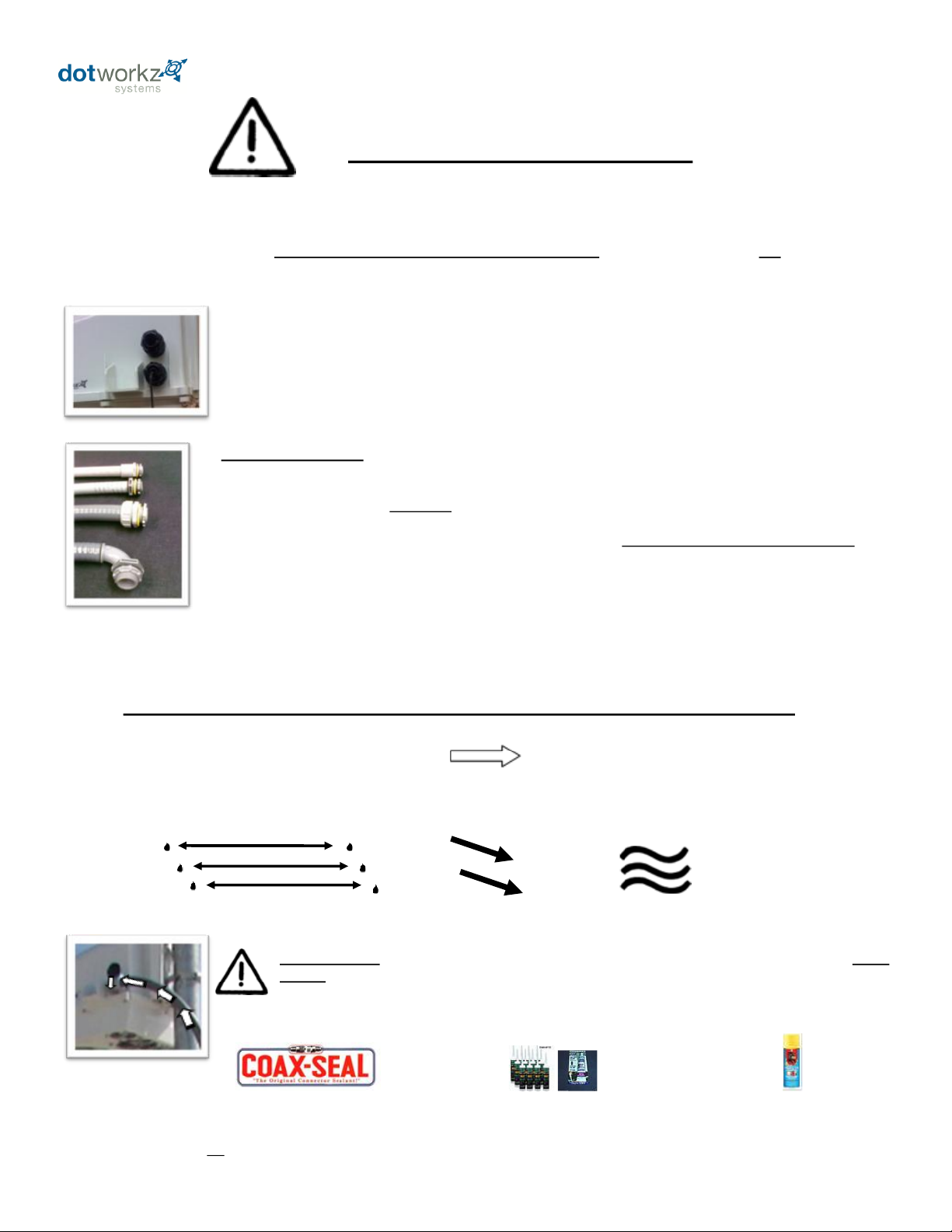
Conduit Guidelines:
1) If wires, cabling, or conduit are coming at enclosure wire entry level, or above, always create a drip loop.
2) Please use only approved watertight electrical conduit and connectors, IP66 or better, with proper seals and
fittings installed & fully seal.
3) Then, after all wire and cables are installed into enclosure, Seal wire entry ports inside of enclosure with
any number of commercially available sealing putty’s, Silicone Sealant, or similar products that are approved by
applicable local and relevant electrical codes.
SHOCK HAZARD! Failure to fully seal enclosure wire and cabling entry ports may lead to shock
hazard, unsatisfactory product performance, a possibility of damage to electronics in the D2 product,
including camera damage, and damage to integrated electronics due to air driven moisture traveling
thru the conduit, condensing and collecting in the enclosure creating a short circuit hazard.
For optimal performance, your D2 Enclosure designed to be Air & Water Tight to eliminate any moisture, dust, and insect damage,
safety, performance, reliability, and maintenance related issues.
Use of Electrical Conduit, without sealing the cable feeds / inside wire feed tube within Camera Enclosure, will subject the
inside of your enclosure to possibility of condensation driven moisture, dust, and insect contamination hazards.
Dotworkz has provided each D2 with two Cable Gland Strain Relief seal ports that fully seal enclosure
to an IP68 rating, Waterproof and Airtight Seal. (Holes on enclosure are 7/8” diameter, ready for standard ½” I.D.
NPT connector, or PG13 fittings.)
However, we realize our customers are retrofitting these connectors with electrical conduit fittings.
We acknowledge this industry customization and installation practice, and would like to guide customers to
properly install these products.
Humid Air
Condensing to Water
FORCES AT WORK IN ANY UNSEALED, CONDUIT WIRE FEED ENCLOSURE SYSTEM
EXPANDING HEATED AIR IS PUSHED INTO ENCLOSURE THEN COOLS &
CONDENSES, HUMID AIR CONDENSES ON SURFACES INSIDE ENCLOSURE
WARM/MOIST IN UNSEALED CONDUIT MOVES THRU CONDUIT FEEDS
EXPAND & CONTRACT WHEN CONDUIT HEATS & COOLS WITH OUTSIDE
TEMPERATURES
Dotworkz does not endorse, nor has it evaluated any of these products. Test products first, and follow all manufacturers’ instructions. Follow all applicable
electrical and building codes and installation guidelines. End user assumes liability for applicability of these products and their effectiveness and incurred liability in using
these products.
Arrows illustrate air flow within
conduit when wire feed is not sealed
within enclosure
Electrical Putty Silicone Sealants
Expanding Foam Sealant
(use very sparingly)
Electrical Conduit Guidelines
Dotworkz supplies two ½” diameter foam conduit plugs, that when installed, will assist in sealing off airflow in conduit feed
thru, at cable entry inside of enclosure. Putty or Sealant can be used in conjunction with these plugs, to assure a full seal inside
enclosure cable feed entry.
2
Page 7

Foam Conduit Feed Plugs for ½” I.D. Conduit
VENT STOPPER PLUGS for Conduit
QUICK INSTALLATION GUIDE
1) Pull wires to final installed length.
2) Open Vent Stop Plug and install over wire.
3) Pinch Plug to compress over wire, and
insert into conduit feed mouth.
4) Push plug into conduit mouth with finger
tips till it flush with outside of fitting.
5) Repeat steps 1-4 for any other conduit
feeds as needed.
6) To assure an airtight seal, caulk around
wires and cables, coating entire plug surface
with sealant.
Prevents Humid Air exchange from venting thru electrical conduit into Dotworkz sealed enclosure.
Thus eliminating condensation issues within Dotworkz sealed enclosures.
3
Page 8

PAN-IP-1 Module
Internet Module
Fastener pack for D2
Enclosure
Panasonic
HE50 Camera
Dotworkz Power
Pack Pole Mount
for COOLDOME
Dotworkz D2 Enclosure
COOLDOME or Heater Blower
Enclosure Kit Components
PAN-FB-3 Module
Fiber Module
PAN-ST-2 Cable
Adapter Cable
Dotworkz EZ-Lock
Pole Mount
or
or
or
Dotworkz D2
Enclosure
D2-HB-MVP-50-2
Dotworkz Enclosure
Environmental Control
Panasonic
HE50 Camera
Link Module
Options
CD-12VDC: COOLDOME- 12 VDC Active Air Conditioning
Panasonic HE50 Camera:
Video Link Module Options:
Model Code
Dotworkz D2 Enclosure
HB-MVP: Heater Blower- Multi-Volt Platform
Dotworkz Enclosure Environmental Control:
“H” model: Panasonic AW-HE50HN Camera
“S” model: Panasonic AW-HE50SN Camera
1: IP Internet Protocol Module for “H” series camera
2: Standard Serial Input Module for “S” series camera
3: Fiber Optic Module for “S” series camera
Enclosure Kit Model Code
Manual pack
for D2
- #1 & #2 Phillips head screw driver
-#1 Flat Blade screw driver or smaller
- 3/8 Socket wrench, nut driver, or adjustable wrench
- 5/16 Socket wrench, nut driver, or adjustable wrench
- 7/16 Socket wrench, nut driver, or adjustable wrench
- 7/32 Socket wrench, nut driver, or adjustable wrench
- 11/32 Socket wrench, nut driver, or adjustable wrench
- Wire stripping tool
Tools recommended for Enclosure & camera mounting
Customer to Provide Mounting Hardware or Strapping to secure Enclosure and Mounts to Pole or Wall
Bracket will accept up to ¾” wide Stainless Steel Strapping
Lag bolt clearance holes (4) up to 5/16" dia. (bracket 4.0" deep on Power Pole mount) (1.5" deep on EZ-Lock)
4
Page 9

Step 1: Install Module into D2 Enclosure for (IP-1 or FB-3) Options
Use carton insert as shown to protect bubble
lens while installing modules
Ready enclosure for module as shown IP-1 Module
Locate & Release Camera Cable and
12VDC Power Quick Connector from
tie inside D2
Plug in mating power Quick
Connector from Module
Install Module loosely into housing
Keep camera power cable accessible
Machine Screws #8-32
x 3/8" (4) SS
Secure Module as shown below into D2
2.5" tall Stand-Offs
Aluminum (4)
Stand-Off’s are mounted to four front threaded inserts
and will be used to mount camera mounting plate
Machine Screws secure rear four mounts
-over pre-installed power module
Rear of Enclosure
Front of Enclosure
Do Not Over-Tighten: To
avoid shearing or stripping
Aluminum Standoff’s
Gently but Securely tighten Standoffs
Camera & Module Power Cables
Fasteners
Components Needed
Remove stopper plug and install cable gland strain relief as shown, seal o-ring remains on outside
Installing second Cable Gland / Strain Relief Port on D2
Shown is an example of fully
installed cable glands with
installed cabling, see applicable
section for cabling guide
FB-3 Module
or
5
Page 10

FB-3 Module
Fiber Video Stream & Control
BNC/ Coaxial to
Monitor Screen
BNC/ Coaxial to
Monitor Screen
Video Fiber
Reciever
Video Fiber
Receiver
Video Fiber
Transmitter
Video Fiber
Transmitter
IP Control
Fiber Converter
Control by
Serial to Fiber
Converter
Control by Serial
to Fiber Converter
Serial Control Interface Cabling
Ethernet Control Interface Cabling
Inside D2 Enclosure
Inside D2 Enclosure
Monitor & Control Station
Monitor & Control Station
Each FB-3 Fiber Module has three Fiber transmitter components on the
Bracket. The FB-3 module is to be installed into D2 outdoor camera housing. There
is one Video fiber transmitter on the FB-3 module which is always used, while there
are two possible configurations of interfacing Control fiber of the HE50S camera on
this module. Only one will be used.
IP Control
Fiber Converter
Panasonic HE50S
Panasonic HE50S
Panasonic AW-RP50
Remote Camera Controller
Panasonic AW-RP50
Remote Camera Controller
Only one control interface module is used on the FB-3 module, and which one is used depends on
existing controller infrastructure you the end user already has, or end user preference if none already exists.
The Monitor & Control Station set up will dictate whether Serial or Ethernet interface is used to complete the
camera control part of installation.
A compliment of Modules must be integrated on Monitor and Control side of installation to encode &
decode fiber signals as shown below.
Typical Video Fiber
termination for AJA ModuleSingle Mode Fiber 1310nm
Compatible cable with Single
Simplex LC Connector
Typical Fiber Pair termination for
Control Modules For SerialComm:
Single Mode 1310nm Fiber Cable
2 X ST Connectors or
2 X SC Connectors
The following are examples of Cabling for these two Control layouts:
The Video fiber converter uses one single mode fiber to transmit to your Monitor & Broadcast
station, while the Control fiber converters use two single mode fiber cables. Two control modules are on the
FB-3 module; one for Serial control interface, the other for Ethernet control interface.
(Components only: Bracket & excess components not shown for wiring clarity)
6
Page 11
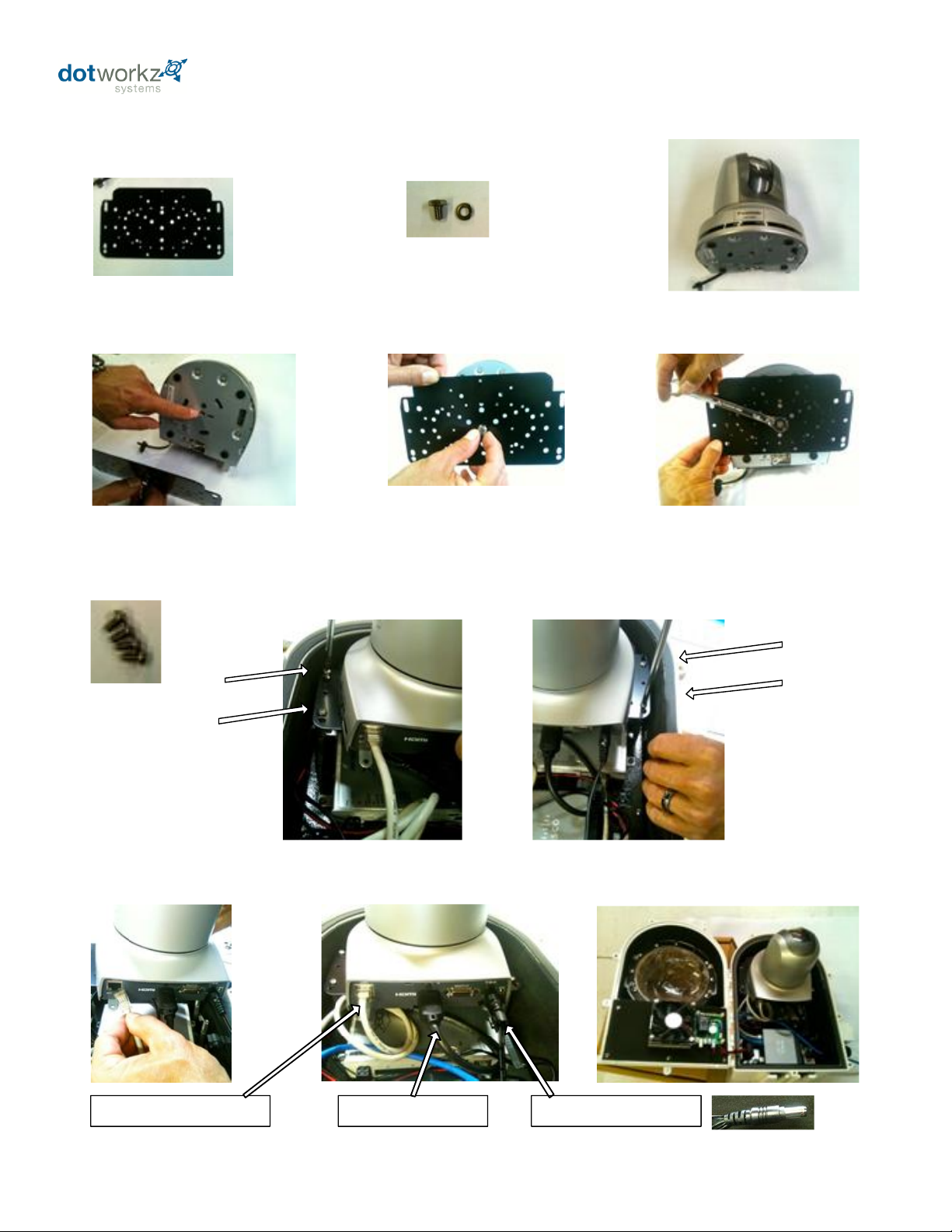
Step 2: Install Panasonic HE50 Camera into D2 Enclosure
Locate these components for assembly
Dotworkz Camera Bracket
¼”-20 x 3/8" Bolt
w/ lockwasher
Panasonic HE50 Camera
Fasten Camera to Bracket
Note center threaded insert location
on Panasonic HE50 Camera
Orient bracket to bottom of camera as shown. Use
center hole on Dotworkz Camera Bracket and hand
thread bolt & lockwasher to camera’s threaded hole
Square camera base to Dotworkz
Camera Bracket & tighten securely
with 7/16" wrench
Fasten Camera & Bracket into D2 Enclosure on 2.5" standoffs
Machine Screws #8-32
x 3/8" (4) SS
Plug 3 Cables into Rear of Camera
Camera & IP-1 installed into Dotworkz D2-CD
Plug in RJ45 patch cable
connected to IP-1/ Cisco router
HDMI from HDMI IN on video
encoder on IP-1 board
12VDC Camera Power Cable from
pre-installed power module
Do Not Over-Tighten: Gently but
securely tighten these screws as
to avoid stripping or shearing
Aluminum standoffs
Shown for “H” series HE50 camera
(Use serial cables provided -plugged to back of “S” series camera for ST-2 & FB-3 options)
7
Page 12

Step 3: Power & Cable Hook Up
Pre-wiring High Voltage Input
Locate Power Pack Pole
Mount high voltage input
box
Remove High Voltage
input Wiring Box by
removing two machine
screws that fasten it to
metal bracket
Then, Pull customer
provided wiring first thru
one of the four round cable
ports on metal bracket,
then thread cable thru
cable gland port on small
electrical box
Using provided waterproof
wire nuts, mate three
corresponding wires to step
down power supply input
wiring
Tighten Strain relief nut around
wire just installed, then Reinstall plastic box onto Metal
Bracket using original fasteners.
Mating Enclosure to Bracket
Locate 12VDC Cable from
power supply output, this
go into D2 enclosure
First feed thru round
port on metal bracket
as shown
Then install the lower
mounting bolts 3/8"-18 x 1"
on bracket, leaving hex
head protruding about 3/8"
Install two upper bolts on
rear tabs including washers
provided, securely fasten,
but do not over-tighten
First feed thru round port on metal bracket
Low Voltage 12 VDC Cabling
Ethernet Cable Installation
The provided Dotworkz D2 COOLDOME enclosure is Powered by 12 VDC Only, and must use step down Power Pack Pole Mount to be powered by High Voltage
Never apply High Voltage directly to inputs inside D2 COOLDOME enclosure
Feed Cat5e/ 6e cable thru port as shown Plug into any open port on Cisco router
Securely tighten seal nuts on all
cabling for proper seal and cable
strain protection
Close enclosure by shutting
lower hinged clamshell
Tighten all Six closure screws
around sides and rear of D2 to
fully seal
Shown is an example of enclosure
ready to Strap mount to a pole, or
lag bolt to wall
Using a small flat blade screw driver, secure wires to color coded terminals as shown
Slide D2 Keyhole mounts on
rear of enclosure to mate to
these lower bolts
Power must be shut off during installation. Installation must be done by a qualified electrical technician. Read and Understand all product instruction before installation.
Always follow local and applicable electrical codes and safety standards. Contact applicable manufacturer if you have any questions on any part of this product installation.
Shown for D2-CD-12V-50-1 Option
For HB-MVP Option, skip to MVP pages
8
Page 13

Site Power Available
110 – 220 VAC
Power Source – Single Phase Only
24 VAC/VDC
Step Down Transformer
High Voltage to 24 VAC
Site Power Available
MVP Voltage Matrix: Enclosure Input – Camera Output
Input Voltage to Enclosure
The MVP Enclosures can be powered by Inputs of either High Voltage 110-220 VAC. Or Low Volt 24 VAC/ VDC
Or
Output Voltage to Power Camera
MVP provides step down voltage to supply camera power for 12VDC, and 24V Cameras. 24V Camera Supply
24V output depends on Site Power Input, for either 24V Direct Current, or Alternating Current (see table above)
Voltage Matrix for Input / Output
*Optional 24VAC Transformer Module available
for 24VAC only cameras to convert 110-220 VAC to 24 VAC (sold separately)
Power Chassis integrated
into D-Series MVP
9
Page 14

10
Page 15

11
Page 16

12
Page 17

D2 Exploded Detail
13
Page 18

D2 Mounting Detail
14
 Loading...