

Page 1
TECHNICAL DATA
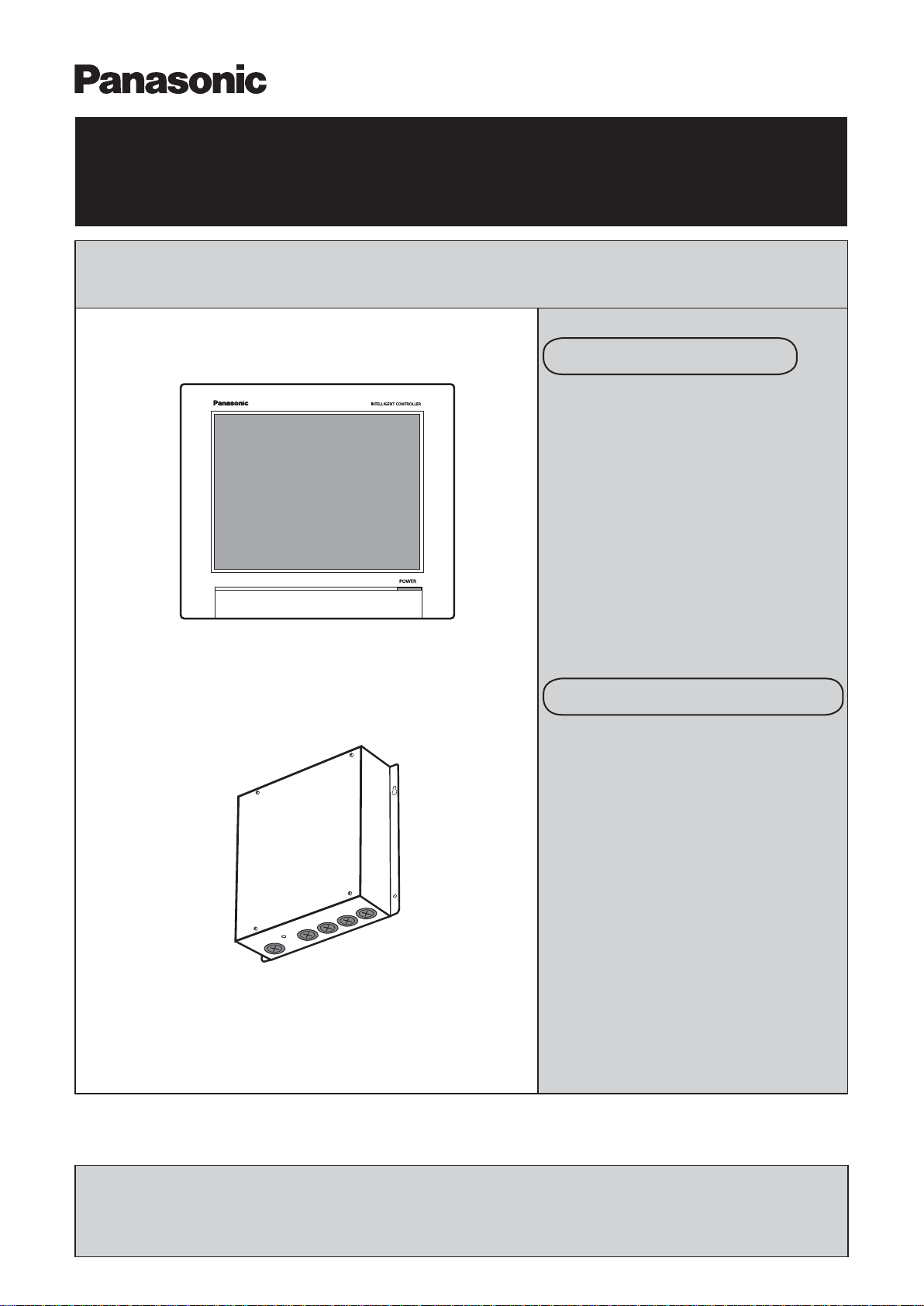
Intelligent Controller
■
Intelligent Controller
Issued March 2017
Intelligent Controller
CZ-256ESMC3
Order No. SBPAC1703004CE
Communication Adaptor
■
Communication Adaptor
CZ-CFUNC2
★ The appearance and specifi cations of this unit and the contents of this Technical Data may be changed
without notice due to performance improvement or other reasons.
Panasonic Corporation
Commercial Air-Conditioner Business Unit
REFERENCE NO. TD831198-00
Page 2

Table of Contents
Page
■
Safety Precautions 1
■
Note 2
■
Fault diagnosis 3
■
Various procedures 14
Display and settings for the communication adaptor board 14
―
― Communication adaptor microcomputer rewrite procedure 34
― Intelligent Controller software update procedure 36
― Replacement of SD card, and operation procedure at time of failure 37
― Procedure for replacing touch panel LCD 41
― Procedure when adding/removing a unit 44
― Procedure when entering or leaving an area mid-period 45
■
Operating Instructions 46
Intelligent Controller 46
―
■
Installation Instructions 149
Intelligent Controller 149
―
― Communication adaptor 154
■
Intelligent Controller web settings 162
Advance check sheet 162
―
― Web setting 167
― Outgoing email settings 173
■
Input of the admin number (password) 175
Page 3
Safety Precautions
●
Before repair work, please read this “Safety
Precautions” carefully and use the unit correctly.
The notes shown here are categorized as “
●
Warning” and “ Caution”, but since they all describe
important contents on safety, be sure to observe
them.
The display and meaning are as follows.
●
This symbol refers to a hazard or
WARNING
CAUTION
Meaning of symbol
●
A “warning” or “caution” item.
Content that must not be done (prohibited
item).
Content that must be done (mandatory item).
unsafe practice which can result in
severe personal injury or death.
This symbol refers to a hazard or
unsafe practice which can result in
personal injury or product or property
damage.
2. Notes on products after repair
WARNING
Be sure to repair the unit with parts that
are described in the service parts list of the
applicable model and use the appropriate tools.
In addition, never modify the product.
Doing so may cause electric shock, overheating
or re.
When moving the unit, be sure to install it securely.
Inadequate strength or incomplete installation
may cause a fall, electric shock, overheating or
re.
Do not damage or modify the power cord.
Doing so may cause electric shock or re.
Placing heavy objects on the power cord, heating
it, or pulling it, may cause damage.
3. Inspection items after repair
After the repair work, make a test run to check
●
whether there is any error and explain the notes on
use to the customer.
1. Notes on repair
WARNING
When performing disassembly repair, be sure to
stop operation and switch off the earth leakage
breaker.
Failure to do so may cause electric shock.
Be careful not to touch the charging unit when
performing a repair or a circuit inspection that
requires a power supply.
Switch off the earth leakage breaker of the unit
before repair work. Failure to do so may cause
electric shock.
Do not repair electrical parts with wet hands.
Doing so may cause electric shock.
WARNING
Scratched or deteriorated power cords or lead
wires must be replaced. Also, do not connect the
power cord partway. Doing so may cause electric
shock, overheating or re.
CAUTION
Check that product mounting positions, wiring
conditions, and connection state such as
soldering, crimp terminal, and so on are normal.
Failure to do so may cause overheating, re or
electric shock.
Do not spray detergent spray or water on the
unit.
Doing so may cause electric shock or re due to
malfunction or electrical short circuit.
When disposing of this unit or other items, please take appropriate measures
such as collecting and erasing internal information to prevent leakage of
condential information.
ー 1 ー
Page 4
Note
1. About noise malfunction
Since communication control is performed by pulse signal, it has the property that it is easily affected by external noise.
In normal use, there is no problem since this is taken into consideration on the circuit, but please note that an inuence may
occur depending on the installation state.
<Items that add high frequency noise to the signal line, causing error in the signal pulse and malfunction>
Places susceptible to noise Symptoms Measures
1. Area with strong radio waves in the
vicinity of a broadcasting station
2. Near to wireless station
3. Near to use of high-frequency sewing
machines or arc welding machines
4. Hospitals (such as X-ray rooms)
5. Near to plasma or liquid crystal
televisions
1. Stops in the middle of operation
2. The liquid crystal display ickers
Prevent noise from being received by
the signal wiring
↓
· Keep away from source
· Adopt shielded wire
ー 2 ー
Page 5

Fault diagnosis
Fault Diagnosis Table of Contents
1. Communication error related
1-1. [C06] error appears on [Alarm list] screen· · · · · · · · · · · · · · · · · · · · · · · · · · · · · · · · · · · · ·4
1-2. [C17] or [Outdoor C17] error appears on [Alarm list] screen · · · · · · · · · · · · · · · · · · · · · · · 5
1-3. [C19] error appears on [Alarm list] screen· · · · · · · · · · · · · · · · · · · · · · · · · · · · · · · · · · · · ·5
1-4. [Disc.] error appears on [Alarm list] screen · · · · · · · · · · · · · · · · · · · · · · · · · · · · · · · · · · ·5
2. Screen display related
2-1. Touch panel LCD does not work (Screen operation is not possible) · · · · · · · · · · · · · · · ·6
2-2. Nothing is displayed on screen · · · · · · · · · · · · · · · · · · · · · · · · · · · · · · · · · · · · · · · · · · · ·· 6
2-3. No indoor unit is displayed on the screen, or the number of units is too small · · · · · · · · · · · · · · 7
2-4. Cannot enter the screen selected in the menu · · · · · · · · · · · · · · · · · · · · · · · · · · · · · · · · · ·7
2-5. Distribution ratio and usage are displayed as 0 · · · · · · · · · · · · · · · · · · · · · · · · · · · · · · · · · · · · · · · 7
2-6. Pulse count does not enter properly · · · · · · · · · · · · · · · · · · · · · · · · · · · · · · · · · · · · · · · · · 8
2-7. Cumulative operation time (or distribution ratio) is counted even though the unit has not been operating · · · 9
2-8. Cannot back up or restore to USB memory device (button is greyed out and cannot be pressed) · · · · · · · · · 9
2-9. Intelligent Controller does not start · · · · · · · · · · · · · · · · · · · · · · · · · · · · · · · · · · · · · · · · · 10
2-10. [Config. change] appears on [Alarm list] screen · · · · · · · · · · · · · · · · · · · · · · · · · · · · · · 11
2-11. Room temperature display is in error ([I/D unit list] screen) · · · · · · · · · · · · · · · · · · · · · · · · · · · · · · ·
11
3. Unit operation related
3-1. Schedule timer does not work properly · · · · · · · · · · · · · · · · · · · · · · · · · · · · · · · · · · · · · · 12
3-2. Unit does not stop (operate) even when Batch stop (startup) input is ON · · · · · · · · · · · · · · · · · · · · 12
3-3. External alarm (operation) output does not turn ON even though unit alarm is detected · · · 13
3-4.
Even if remote controller prohibition is set, function settings can be individually changed by the remote controller · ·13
ー 3 ー
Page 6
1. Communication error relatedFault diagnosis
Note》 The meaning of the symbols below are as follows.
《
· Adaptor Communication adaptor
· MAIN board MAIN board of communication adaptor
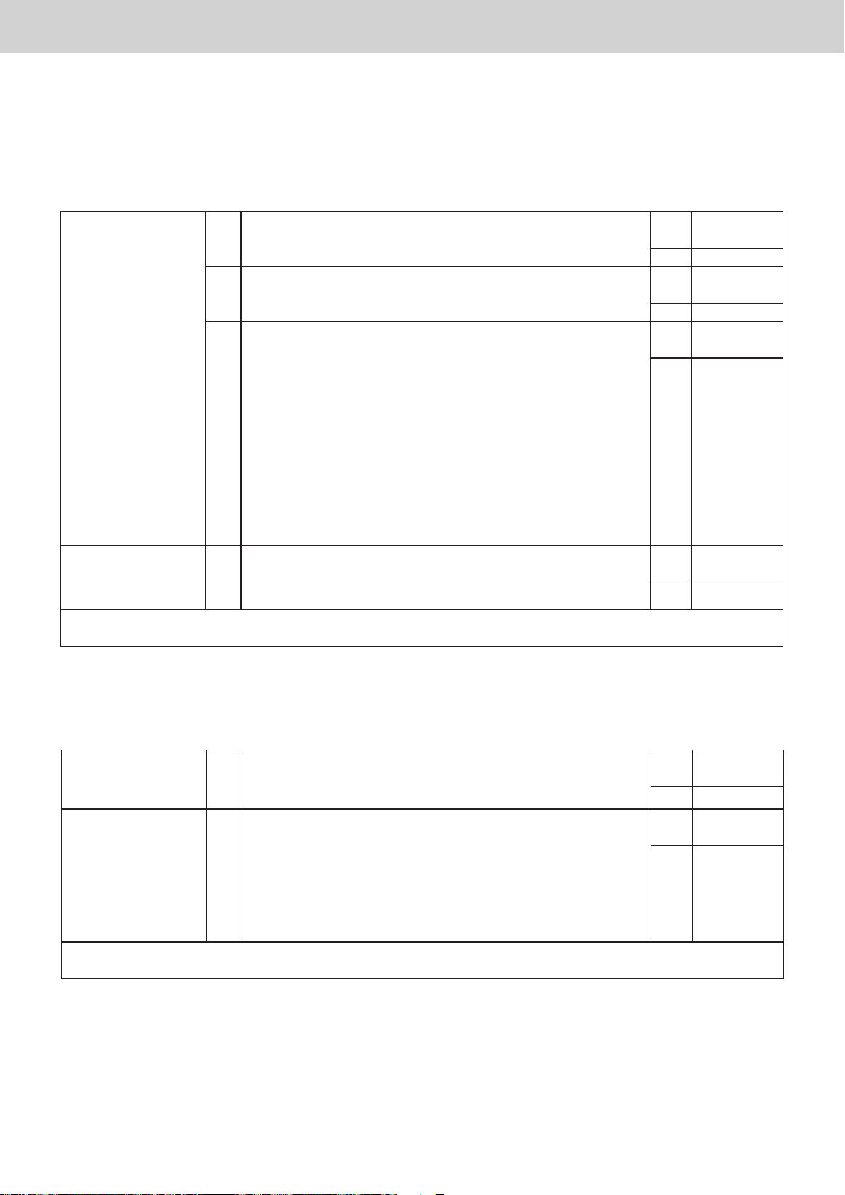
1. Communication error related
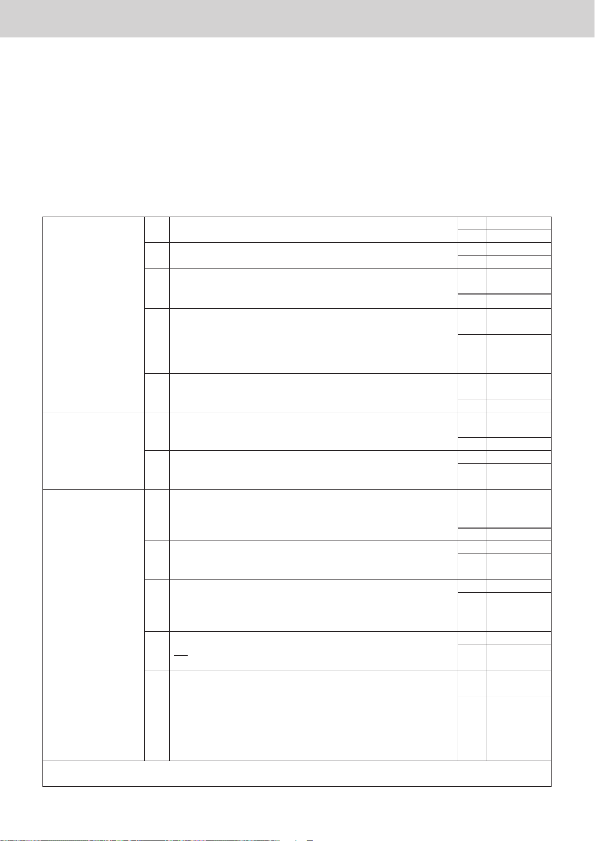
1-1. [C06] error appears on [Alarm list] screen
Detection method
1
If the Intelligent Controller cannot receive data from the communication adaptor board for a certain period of time
or longer, or if in an error is detected in the received data.
Diagnosis of failure
2
1. Communication
adaptor
(Power supply
system)
2. Communication
adaptor
(Communication
system)
3. Construction /
settings related
4. Replace the communication adaptor board for which there is an alarm
Or, replace the product main unit
1-1 Is anything displayed on the 7-segment LED (6) on the board? Yes 2-1
No 1-2
1-2 Is the power switch on the board ON? Yes 1-3
No Turn ON
1-3 Is there a disconnection or open circuit in a connector on the
board?
· CN 5 (white 6P)
1-4 (External adaptor only)
Is there a disconnection or open circuit in a connector on the
power supply board?
· CN1 (white 5P)
· CN2 (white 4P / 7P)
1-5 Has the fuse (F1) of the board burned out? Yes
2-1 Is there a disconnection, looseness, an open circuit, or a short
circuit in the wiring of 11P or 12P [ADAPT] (RS485) of the 20P
terminal block CN2?
2-2 Is the wiring polarity of 11P, 12P “ADAPT” (RS485) of the 20P
terminal block CN2 correct? (+, -)
3-1 Did you change the adaptor address settings since the
Intelligent Controller started?
3-2 Are the “LINK connect Yes/No” settings correct?
(See the “Display and settings on the communication adaptor
board” section)
3-3 Is jumper plug CN032 of the communication adaptor at the end
of the crossover wiring set to “B” (with terminating resistance)?
* Built-in board of Intelligent Controller main body set to “B” (with
terminating resistance).
3-4
Is jumper plug CN032 of the communication board that's located
not at the end of the crossover wiring set to “A” (with terminating
resistance)?
3-5 Are there any of the following types of deciencies in the
construction of the communication adaptor control wiring?
· Power lines and bundled lines or running in parallel
· The total extension exceeds 1 km
· It is not crossover wiring (there is a branch point)
· Shielded wire is not used
· The shield is grounded on both sides or not grounded
Yes Correct
wiring
No 1-4
Yes Correct
wiring
No 1-5
Replace the
fuse
No 2-1
Yes Correct
wiring
No 2-2
Yes 3-1
No Correct
wiring
Yes Undo or
check
conguration
No 3-2
Yes 3-3
No Modify
settings
Yes 3-4
No Set it to “B”
Yes 3-5
No Set it to “A”
Yes Reconstruct
properly
No 4
ー 4 ー
Page 7
1. Communication error relatedFault diagnosis
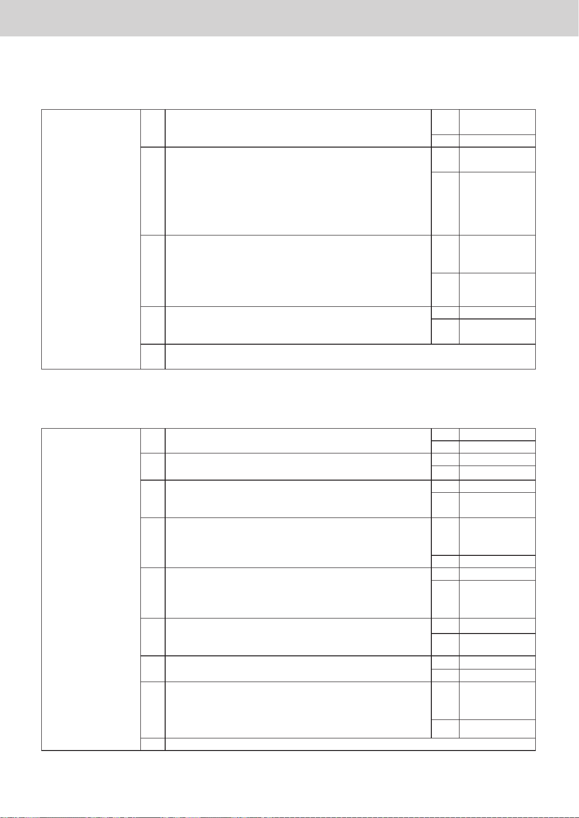
1-2. [C17] or [Outdoor C17] error appears on [Alarm list] screen
Detection method
1
If the communication adaptor cannot receive data from the indoor or O/D unit for a certain period of time or
longer, or if an error is detected in the received data.
Diagnosis of failure
2
1. Unit 1-1 Is there a unit that is turned off? Yes Turn on the
power
No 1-2
1-2 Is there looseness, a disconnection, an open circuit, or a short
circuit in the inter-unit control wiring connection?
1-3 Are there any of the following types of deciencies in the
construction of the inter-unit control wiring?
· Running in parallel with power lines
· Branch points exceed 16 places
· The total extension exceeds 1 km
· There is re-branching after branching
· There is a branch point with many branches (“star” or
“octopus” conguration)
· The distance between one branch point and the next branch
point is 2 m or less
· Defective termination resistance settings (too low or too high)
· When shielded wire is used, the shield is grounded on both
sides or not grounded
2. Intelligent Controller 2-1 Is there looseness, a disconnection, an open circuit, or a
short-circuit in the wiring of 1, 2 (LINK1) or 4, 5 (LINK2) of the
Intelligent Controller's 27P terminal board?
Yes Correct
wiring
No 1-3
Yes Reconstruct
properly
No 2-1
Yes Correct
wiring
No 3
3. Replace the communication adaptor board for which there is an alarm
Or, replace the product main unit
1-3. [C19] error appears on [Alarm list] screen
Detection method
1
When there are multiple adaptors with the same address in one communication adaptor control wiring system.
Diagnosis of failure
2
1. Communication
adaptor
2.
Communication
adaptor
control wiring
3. Replace the adaptor board for which there is an alarm
Or, replace the product main unit
1-1 Is there more than one adaptor with the same address in one
communication adaptor control wiring system?
2-1 Are there any of the following types of deciencies in the
construction of the communication adaptor control wiring?
· Power lines and bundled lines or running in parallel
· The total extension exceeds 1 km
· It is not a crossover wiring (there is a branch point)
· Shielded wire is not used
· The shield is grounded on both sides or not grounded
* After correctly setting the adaptor address, perform [Check conguration] on the Intelligent
Controller screen, to conrm.
* [Check conguration] is displayed under [Settings] → [System settings].
Yes Modify
settings *
No 2-1
Yes Reconstruct
properly
No 3
1-4. [Disc.] error appears on [Alarm list] screen
Detection method
1
It is the same as for “1-1. [C06] error appears on [Alarm list] screen”. However, if an air conditioner is connected
to the communication adaptor, a “Disc.” error is displayed on that air conditioner (Indoor unit, Outdoor unit).
Diagnosis of failure
2
Refer to “2 Diagnosis of failure” in 1-1.
ー 5 ー
Page 8
2. Screen display relatedFault diagnosis
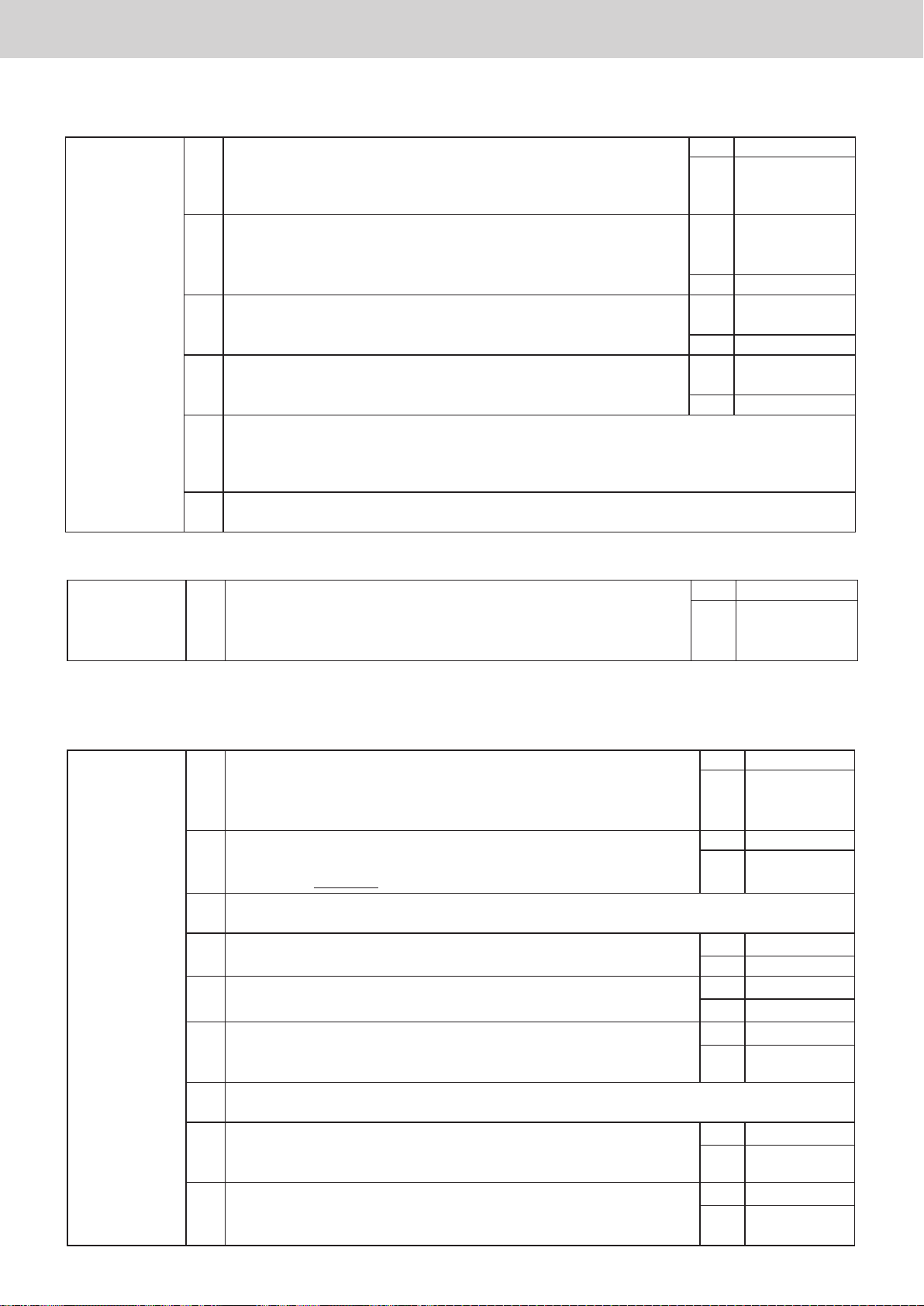
2. Screen display related
2-1. Touch panel LCD does not work (Screen operation is not possible)
1. Intelligent Controller 1-1 Is [InitCom...] displayed? Yes Wait till it
disappears
No 1-2
1-2 Is the following displayed?
· Checking cong...
Wait...
· Updating cong...
Wait...
· Calculating distribution...
· Please wait a moment now
1-3 Is it processing one of the following?
· Backup to USB memory device
· Restore from USB memory device
· Distribution calculation processing
Yes Wait till it
disappears
No 1-3
Yes Wait till
processing
nishes
No 1-4
1-4 Restart the Intelligent Controller (turn the power off / on) and
wait for it to start up.
Is the touch panel working at this time?
1-5 Replace touch panel LCD
Or, replace the product main unit
Yes
OK (END)
No 1-5
2-2. Nothing is displayed on screen
1. Intelligent Controller 1-1 Is the power indicator (green) on the front lit? Ye s 1-7
No 1-2
1-2 Is the main power supply ON? Yes 1-3
No Turn ON
1-3 Is power supplied to the power terminal board? Yes 1-4
No Connect the
power supply.
1-4 Is fuse F1 blown? Yes Replace the
power supply
board.
No 1-5
1-5 Is there a disconnection or an open circuit of a connector on
the MAIN board?
· CN5 (white 6P)
· CN9 (white 2P)
1-6 Is anything displayed when the main power supply of the
Intelligent Controller is turned OFF once and then turned ON
again?
1-7 Is anything displayed when you press somewhere on the
screen?
1-8 Remove the sheet metal cover on the LAN connector
(2 sides).
At this time, is the SD memory card not installed or
defective?
Yes
Correct wiring
No 1-6
Yes (END)
No 1-9
Yes (END)
No 1-8
Yes
Insert it correctly,
then turn ON the
power again
No 1-9
1-9 Replace Intelligent Controller
ー 6 ー
Page 9
2. Screen display relatedFault diagnosis
2-3. No indoor unit is displayed on the screen, or the number of units is too small
1. Intelligent
Controller
2-4. Cannot enter the screen selected in the menu
1. Intelligent
Controller
* When entering each menu on the Intelligent Controller, the PIN is set on the Settings → IntlgtCtrlr maintnce → Initialize screen.
2-5. Distribution ratio and usage are displayed as 0
If the distribution ratio is 0%, start from “1-1”.
If distribution ratio is displayed, but usage is 0, start from “1-7”.
1. Intelligent
Controller
* 1 Diagnosed as item “2-6. Pulse count does not enter properly”.
Can you perform the basic settings for the indoor unit?
1-1
* For the basic settings of an indoor unit, select [I/D unit settings] from
[Settings] → [System settings], check the details of the setting, place a
check in the [Register] eld and register with the [Register] button.
1-2 Is the [No-comm mode] setting set to [YES]?
* [No-comm mode] setting is displayed under [Settings] → [A/C
maintenance] → [A/C communication settings] → [Next].
Yes 1-2
No Register
Yes Set it to “NO”
Check
conguration
No 1-3
1-3 Is the setting of [A/C conctn] set to [None
]
? Yes Correct the
setting to “ON”
No 1-4
1-4 Are you connecting 17 or more linked air conditioners? Yes Reduce to within
16 links
No 1-5
1-5 What happens when you perform [Check conguration]*?
[
Cong. has been chngd
Conrm conguration?] is displayed → [Begin cong
[
The conguration has not changed.] is displayed → Go to 1-6
1-6 Refer to the items
“
1-1. [C06] error appears on [Alarm list] screen”, “1-2. [C17] or [Outdoor
]
C17] error appears on [Alarm list] screen” and check all the same contents
* [Check conguration] is displayed under [Settings] → [System settings].
1-1 Are you registering an admin number (password)?
(Settings → System settings → Web user settings)*
Yes (END)
No
* For screens protected by the admin number (password), refer to
the Operating Instructions.
1-1 When performing time slot integration, is the displayed time slot
selection correct?
(RglHour (RglHour 1 to 8) / OutOfHours / SpcfdDay / AllHours)
Yes 1-2
No Select the
correct time
slot
1-2
When conrming the operation time of the indoor unit belonging to
that area under [Oper./Status] → [Accumult/Distrib] → [I/D unit acc.]
Yes 1-3
1-4
No
screen, are all “0: 00”?
1-3 If the operation time is 0:00, the distribution ratio, charge, and usage are all displayed as 0.
(In the case of time distribution) (END)
1-4 Are the area distribution settings completed?
([Settings] → [System settings] → [Area group name settings] screen)
1-5 Are the distribution settings of the distribution group completed?
([Settings] → [System settings] → [Distribution group settings] screen)
1-6 In the case of an area consisting of all local adaptors, is the
capability value set?
Yes 1-5
No 1-7
Yes 1-6
No 1-7
Yes 1-8
No 1-7
([Settings] → [System settings] → [I/D unit settings] screen)
1-7 Set the contents of 1 - 4, 1 - 5, 1 - 6 correctly. (*)
If [0] is still displayed for usage, go to 1-8.
1-8 Is the count from the pulse meter on?
(Check the [Oper./Status] → [Accumult/Distrib] → [Pulse acc.]
Yes 1-9
No *1
screen)
1-9 Is the pulse unit quantity setting complete?
([Settings] → [System settings] → [Pulse meter settings] screen)
Yes
No Apply settings
*2
ー 7 ー
Page 10
2. Screen display relatedFault diagnosis
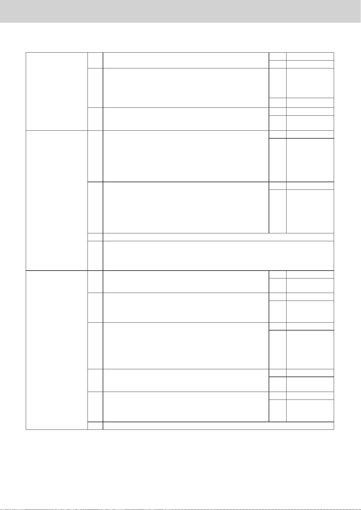
2-6. Pulse count does not enter properly
1. Intelligent Controller 1-1 Is the distribution group correctly set on the [Settings] →
[System Settings] → [Distribution group settings] screen?
1-2 Are you looking at the Cut off data display on the [Oper./
Status] → [Accumult/Distrib] → [Pulse acc.] screen?
(Are the dates (e.g. 08/01 - 08/31) displayed in the upper
right of the screen?)
1-3 When performing time slot totals calculation, is the displayed
time slot selection correct? (RglHour (RglHour 1 to 8) /
OutOfHours / SpcfdDay / AllHours)
2. Communication
adaptor
3. Pulse meter 3-1 Is the wiring to the communication adaptor correct?
2-1 Is the wiring from the pulse meter correctly connected?
Is there a terminal mix-up, disconnection, open circuit, or
short circuit?
(Pi1 to Pi3 of the 27P terminal board on the MAIN board)
Pi1 (7, 8)
Pi2 (7, 9)
Pi3 (7, 10)
2-2 Remove all the wiring of the pulse meter from the terminal
board, and use a wire, scrap of lead wire, or other
appropriate object to short-circuit the input parts (Pi1 to Pi3)
of the terminal board several times while looking at the [Pulse
acc.] screen of the Intelligent Controller. Does the number
of pulses increase correctly? (It may take several minutes to
update the display)
2-3 Replace MAIN board
2-4
If the distance between the pulse meter and the communication adaptor is 20 m or
more, please use a relay.
Even if the distance is within 20 m, please use a relay if you are concerned about the
effect of noise.
Is there a terminal on the meter side with a disconnection,
open circuit, short circuit or the like?
3-2 Is the signal line from the pulse meter denitely a no-voltage
a contact (relay contact)?
* There is polarity in the case of open collector output.
(Number 7 is positive, numbers 8, 9, 10 are negative)
3-3 Remove the wiring from the terminal section, and short-
circuit the wires with each other several times while looking
at the [Oper./Status] → [Accumult/Distrib] → [Pulse acc.]
screen of the Intelligent Controller. Does the number of
pulses increase correctly?
(It may take several minutes to update the display)
3-4 Is there a mistake in connecting the wattmeter and power
line, or the gas ow meter and fuel gas pipe?
3-5 Is the power amount or gas ow rate per pulse for this model
of pulse meter larger than necessary, or is the setting larger
than necessary?
3-6 Investigate the main unit of the pulse meter
Yes 1-2
No Apply settings
Yes Look at the
“Current
(calculating)”
display
No 1-3
Yes 2-1
No Select the
correct time slot
Yes 2-2
No Correct wiring
Yes 3-1
No 2-3
2-4
Yes 3-2
No Correct wiring
Yes 3-3
No Correct wiring
Yes 3-4
No Go back to 2-1
Yes 3-5
No Reconstruct
them correctly
Yes 3-6
No Change meter
model, or modify
settings
ー 8 ー
Page 11
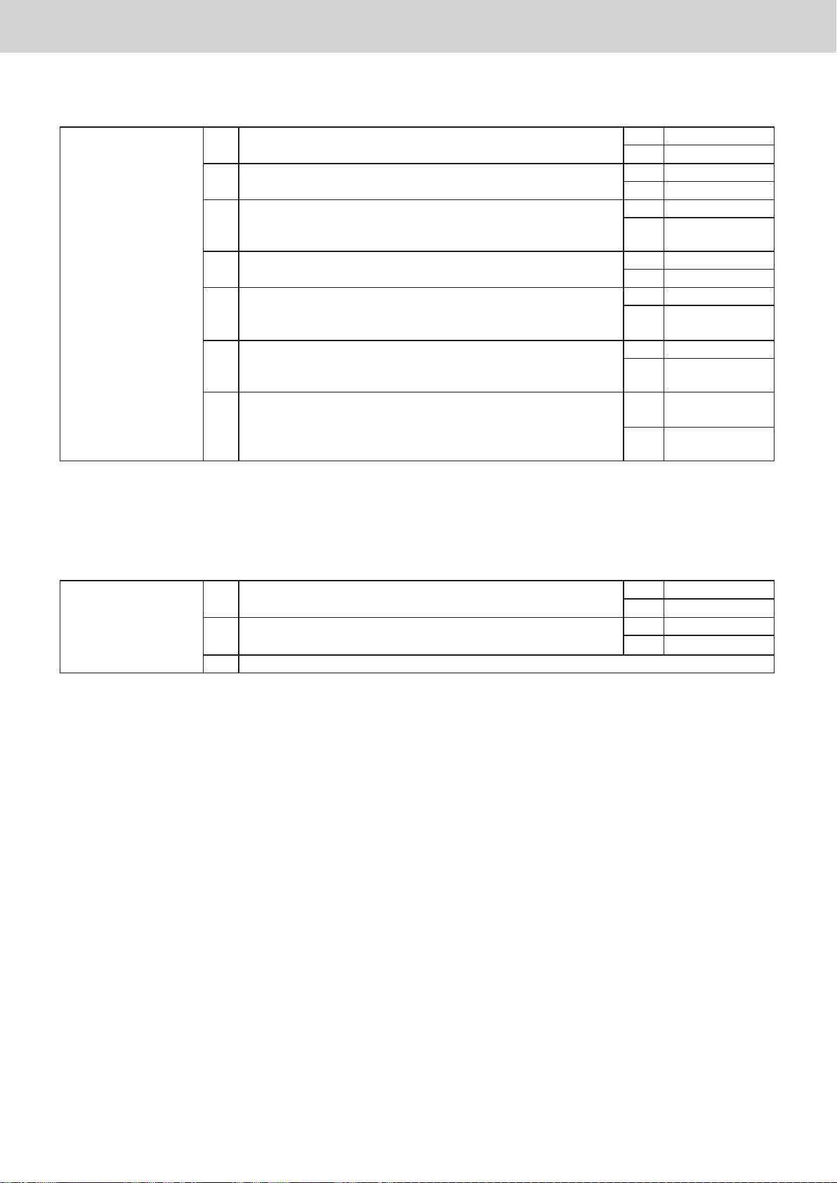
2. Screen display relatedFault diagnosis
2-7.
Cumulative operation time (or distribution ratio) is counted even though the unit has not been operating
1. Intelligent Controller 1-1 Is the cumulative time zero? (Distribution ratio is counted) Yes *1
No 1-2
1-2 Did you not operate the unit but “forgot to stop it”? Yes (END)
No 1-3
1-3 Did the schedule timer or event control work?
(Remote controller, other centralised equipment, external
input, and so on)
1-4 Is there evidence of forced operation of an indoor unit from a
PC or the like during repair service or maintenance?
1-5 When performing time slot integration, is the displayed
time slot selection correct? (RglHour (RglHour 1 to 8) /
OutOfHours / SpcfdDay / AllHours)
1-6 (When using time slot distribution)
Are the timer settings and distribution specied day settings
correct?
1-7 (When using time slot distribution)
Is an OFF timer set at the same time as or close to the
switching of the time slot?
Yes (END)
No 1-4
Yes (END)
No 1-5
Yes 1-6
No Select the
correct time slot
Yes 1-7
No Modify settings
Yes Modify settings
*2
No
* 1 In the Load Distribution mode, standby power is distributed even without operation.
* 2 Avoid setting the OFF timer within about 10 minutes before the time slot switching time.
2-8. Cannot back up or restore to USB memory device (button is greyed out and cannot be pressed)
1. USB memory
device*
1-1 Is the USB memory device properly inserted in the specied
place?
1-2 Is backup or restoration also impossible with another USB
memory device?
1-3 Replace the Intelligent Controller.
* USB memory device specications
Standard type (USB 2.0)
Capacity: 4 GB or more
Precautions for use
· Even if the USB memory device matches the above specications, operation is not guaranteed.
· USB memory device with encryption function (with security software) cannot be used.
Yes 1-2
No Insert it
Yes 1-3
No (END)
ー 9 ー
Page 12
2. Screen display relatedFault diagnosis
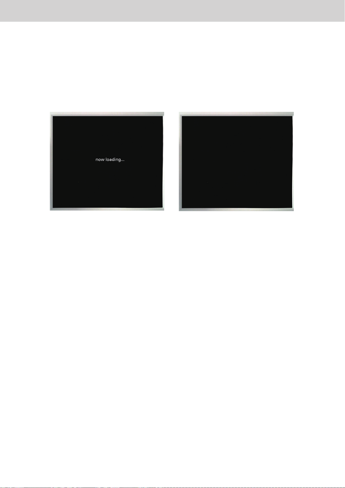
2-9. Intelligent Controller does not start
1. Intelligent Controller does not start
If “now loading ...”
OFF once and then turn it back ON again.
If the device does not start up even after turning on the power again, replace the SD card.
is displayed or the screen remains black 2 even with the power turned on, turn the power
1
1
2
ー 10 ー
Page 13
2. Screen display relatedFault diagnosis
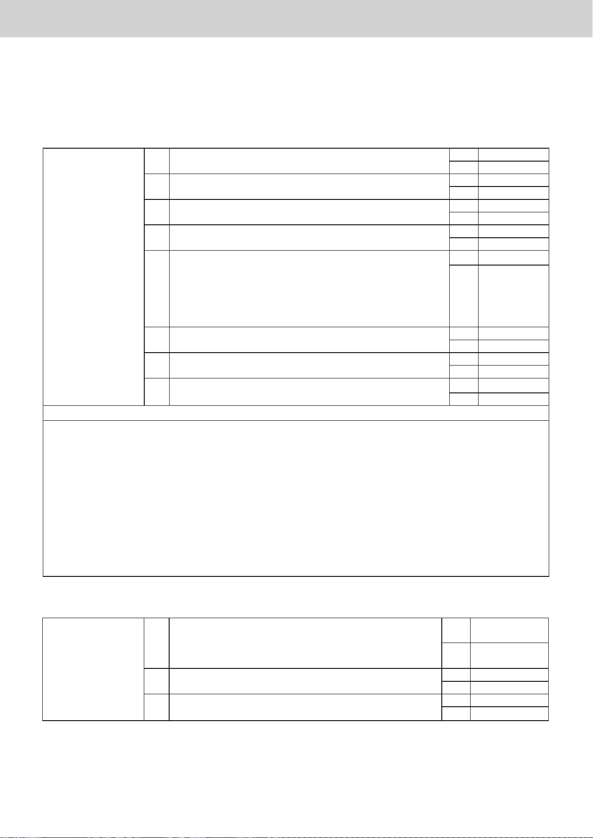
2-10. [Cong. change] appears on [Alarm list] screen
Detection method
1
This alarm is issued when the system conguration (such as number of adaptors, number of indoor units, and
addresses) has changed or may have been changed, and unlike other alarm messages it does not indicate an
error.
Diagnosis of failure
2
1. Unit side 1-1 Have you added or removed indoor unit or outdoor unit units? Ye s 2
No 1-2
1-2 Have you recongured the remote controller group? Yes 1-3
No 1-4
1-3 Is it a group spanning multiple areas? Yes 2
No 1-4
1-4 Did you change [Detailed Settings] of the remote controller? Yes 1-5
No 1-6
1-5
Is it one of the following items?
· Cap of indoor unit
· System address
· Indoor unit address
· ECONAVI Yes/No
· Presence of heater
· Group Main/Sub
· Indoor unit type
· Actual capacity of indoor unit
· Presence of VentOpen
Yes 2
No 1-6
1-6 Did you perform automatic address from the remote controller
or the outdoor unit?
1-7 Have you removed the remote controller and changed the
system to remote-less?
1-8 Although it does not fall under any of the above, does “Cong.
change” appear for no reason?
2 Perform Check Conguration. If the conguration has changed, perform Update Conguration.
3 Check whether the inter-unit control wiring has one of the following deciencies.
· Running in parallel with power lines
· Branch points exceed 16 places
· The total extension exceeds 1 km
· There is re-branching after branching
· There is a branch point with many branches (“star” or “octopus” conguration)
· The distance between one branch point and the next branch point is less than 2 m
· Defective termination resistance settings
· When shielded wire is used, the shield is grounded on both sides or not grounded
· More than 65 indoor units are connected in S-LINK
If [Cong. change] still appears even when these changes are made, replace the MAIN board of the
corresponding communication adaptor.
If only an Intelligent Controller is used, replace the Intelligent Controller.
Yes 2
No 1-7
Yes 2
No 1-8
Yes 3
No (END)
2-11. Room temperature display is in error ([I/D unit list] screen)
1. Indoor unit side 1-1 Does it match the sensor temperature display on the remote
controller?
When using remote control sensor: Sensor address 01
When using body sensor:
1-2 Is the centralised address set?
([Settings] → [System settings] → [Unit settings])
1-3 Is it only in error when heating? (OK except when heating) Yes *1
* 1 When using body sensor with heating, the room temperature after shifting may be displayed.
In this case, it does not match the sensor temperature display of the remote controller.
ー 11 ー
Sensor address 02
Yes Investigate
No 1-2
Yes 1-3
No Apply settings
No
thermistor
Page 14
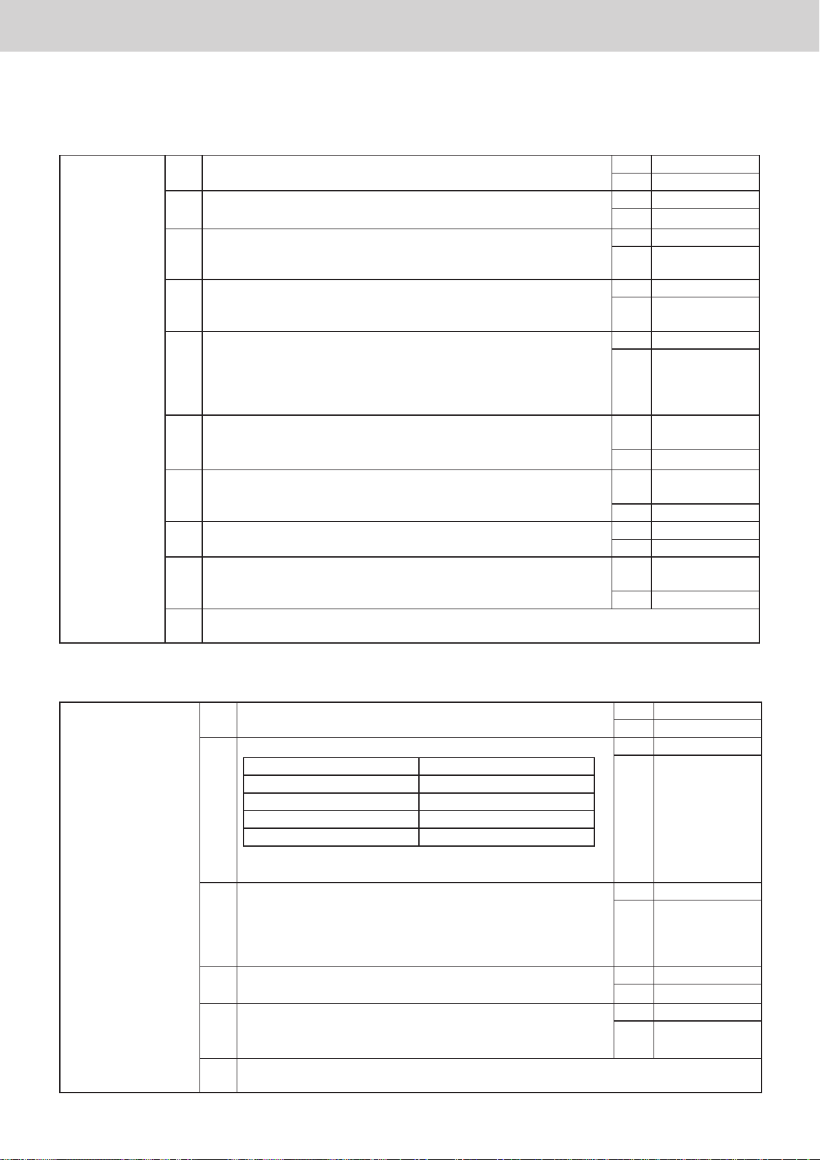
3. Unit operation related
3-1. The Schedule Timer does not work properly
3. Unit operation relatedFault diagnosis
1. Intelligent
Controller
1-1 Have you denitely set [Oper./Status] → [Set schedule]? Yes 1-2
No Apply settings
1-2 Is the timer selected for the indoor unit? Ye s 1-3
No Select
1-3 Is that day set as an area holiday or timer special day for that
indoor unit?
* Area holidays and timer special days work with a dedicated timer
1-4 Is the current date / time setting correct? Yes 1-5
1-5 Did the following happen at the time of the timer?
· Power outage of indoor unit
· Power outage of Intelligent Controller
· Power outage of communication adaptor
· Communication error with air conditioner due to other causes
1-6 Is it set so that the units in one O/D unit system are in different
cooling / warming modes?
(Not allowed because of mismatch of heating and cooling)
1-7 Depending on the model, are the settings invalid?
(Example: Trying to set a cooling-only model to heating
operation)
1-8 Are settings applied that change directly from cooling (dry) to
heating (or vice versa)?
1-9
Is the timer also used for other equipment (remote controller,
Schedule Timer, etc.)?
1-10
Set a timer for [OFF] or [Fan] for one minute before (for example) switching the cooling /
heating mode.
Yes (END)
No 1-4
No Correct the
settings
Yes (END)
No 1-6
Yes
Modify timer
settings
No 1-7
Yes
Modify timer
settings
No 1-8
Yes 1-10
No 1-9
Yes
Check setting
conict.
No
3-2. Unit does not stop (operate) even when Batch stop (startup) input is ON
1. Intelligent Controller
or
communication
adaptor
1-1 Have you denitely set [System Settings] → [Event Control]? Yes 1-2
1-2 Is the connection of Batch stop (startup) input correct?
Intelligent Controller Communication Adaptor
27P terminal board 20P terminal board
20, 21 (DI1) 16, 17 (DI1)
20, 22 (DI2) 16, 18 (DI2)
20, 23 (DI3) 16, 19 (DI3)
Is there a mistake in the connection, or a disconnection or
open circuit?
1-3 When the wiring of the Batch stop (startup) input signal is
removed from the terminal board and the Batch stop (startup)
input part of the terminal board is short-circuited by using an
appropriate wire, or broken piece of lead wire, does the unit
turn OFF (ON) correctly?
1-4 Is the Batch stop (startup) input signal input with no voltage
“a” contact or a static signal?
1-5 On the [Settings] → [System Settings] → [I/D unit settings]
screen, 1 is there no check mark in the [Register] eld, or is
it 2 [Not managed]?
1-6 Replace MAIN board of communication adaptor connecting bulk input signal.
If only an Intelligent Controller is used, replace the Intelligent Controller.
No Modify settings
Yes 1-3
No Correct wiring
Yes 1-4
No 1-5
Yes Go back to 1-2
No Modify
Yes Modify settings
No 1-6
ー 12 ー
Page 15
3. Unit operation relatedFault diagnosis
3-3 External alarm (operation) output does not turn ON even though unit alarm is detected
1. Intelligent Controller
or
Communication
Adaptor
1-1 Have you denitely set [System Settings] → [Event Control]? Yes 1-2
No Modify settings
1-2 Is the external output wiring properly connected?
Intelligent Controller Communication Adaptor
27P terminal board 20P terminal board
17, 18 (DO1) 13, 14 (DO1)
17, 19 (DO2) 13, 15 (DO2)
Is there disconnection, open circuit, or short circuit?
1-3 Is the load side (alarm device, etc.) properly connected?
(Contact rating: DC30 V, 0.5 A)
1-4 Is the “unit alarm” one of the following?
· Filter cleaning sign
· Engine oil Inspection Sign
· Remote control Inspection Sign
* In the case above, the external bulk warning is not output.
1-5 Replace MAIN board of communication adaptor connecting bulk output signal.
If only an Intelligent Controller is used, replace the Intelligent Controller.
Yes 1-3
No Correct wiring
Yes 1-4
No Modify
Yes (END)
No 1-5
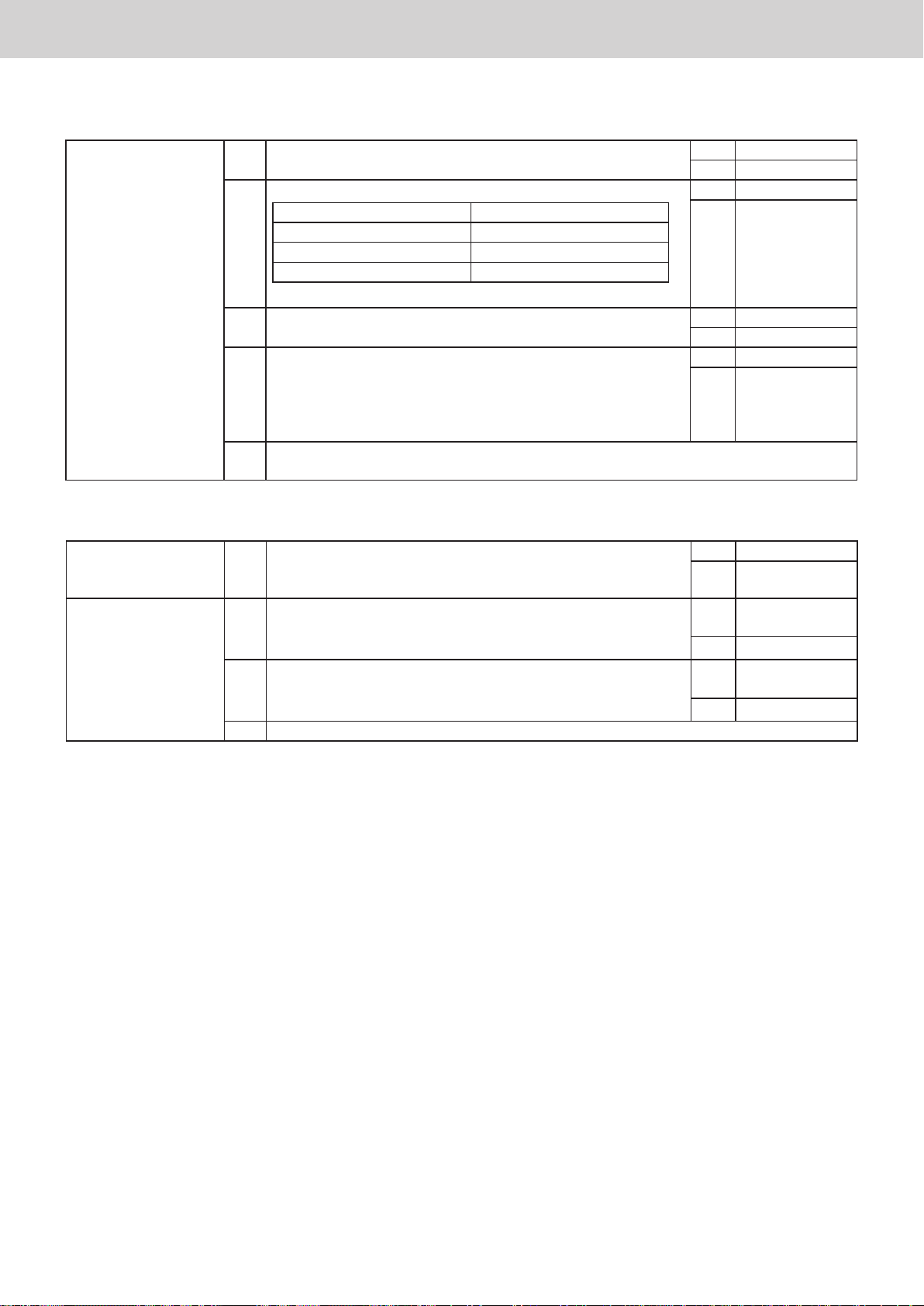
3-4 Even if remote controller prohibition is set, function settings can be individually changed by
the remote controller
1. Intelligent Controller 1-1 Is the centralised address set?
(Conrm on the [Settings] → [System Settings] → [I/D unit
settings] screen)
2. ON / OFF
Controller
2-1 The ON / OFF Controller main-sub changeover of the linked
ON / OFF Controller (ON / OFF CON) is OFF
Is it set to (Main)?
2-2 Is the “centralised control main-sub changeover” of the
linked ON / OFF Controller (ON / OFF CON) set to OFF
(Main)?
2-3
Replace the ON / OFF Controller
Yes 2-1
No Apply settings
Yes
Set it to ON
(Sub)
No 2-2
Set it to ON
Yes
(Sub)
No 2-3
ー 13 ー
Page 16
Various procedures
Display and settings for the communication adaptor board
Display and settings for the communication adaptor board
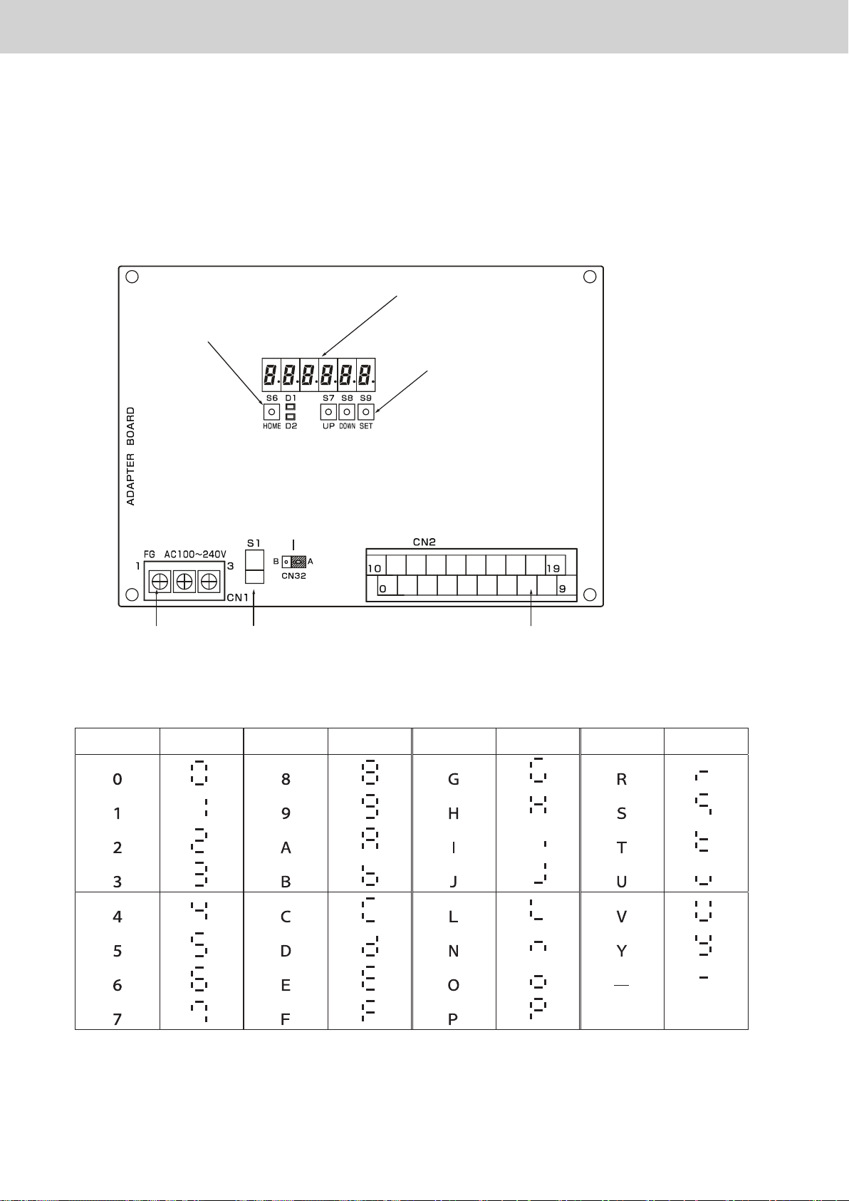
1. Overview
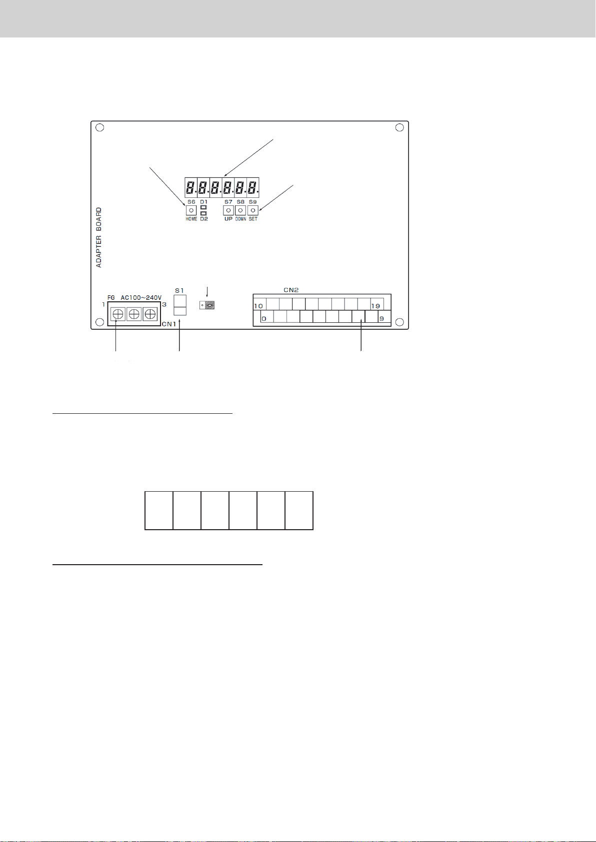
Communication adaptor board
1
It is possible to display/set using the four keys (HOME/UP/DOWN/SET), 6-digit 7-segment and 2 LEDs
•
(red/green).
7-segment numerical display
LED
HOME key
UP/DOWN/SET
keys
Terminating resistance
plug for communication
adaptor control wiring
Power supply
terminal strip
7-segment numerical display
2
Contents Display Contents Display Contents Display Contents Display
Power switch Signal terminal strip
ー 14 ー
Page 17
Various procedures
Display and settings for the communication adaptor board
2. Display immediately after power on
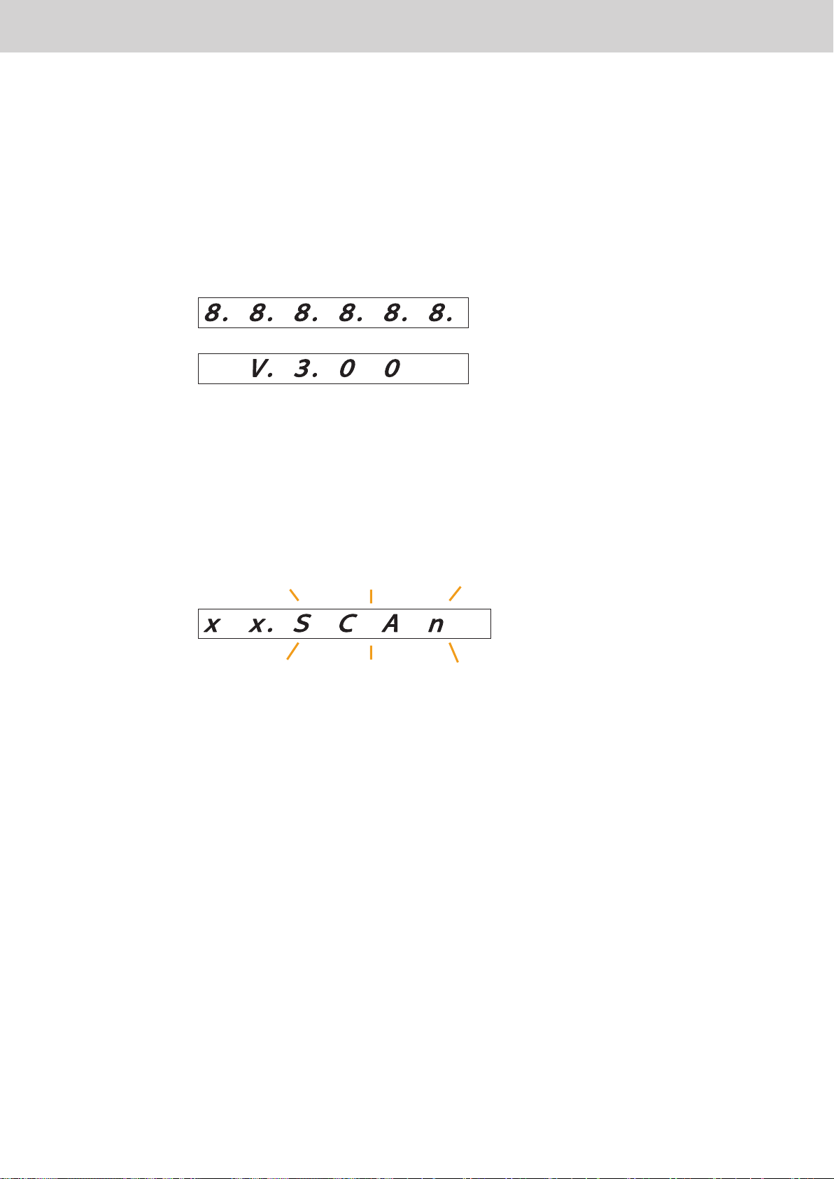
Immediately after turning on the power of the communication adaptor, all the segments light for 3 seconds,
•
then the microcomputer software version is displayed for 3 seconds, then the normal display is displayed.
Power on
(All segments lit: 3 seconds)
(Microcomputer software version display:
3 seconds)
Indication that air conditioner information is being collected is displayed.
Indication for air conditioner configuration
3. Air conditioner information collection in progress indication
(SCAN blinking)
Air conditioner link number (X = 00 to 14)
In the following case, indication that air conditioner information is being collected is displayed.
•
1 When collecting information from the air conditioner immediately after turning on the power.
2 When checking configuration
ー 15 ー
Page 18

Various procedures
Display and settings for the communication adaptor board
4. Indication for air conditioner conguration
While the indication for air conditioner configuration is displayed, information on the configurations of the indoor
•
unit linked system 1 and linked system 2 are alternately displayed for 10 seconds each.
If the touch switch on the adaptor board is not operated, the indication for air conditioner configuration is
•
normally displayed.
(Information on the indoor unit linked system 1:
10 seconds)
(Information on the indoor unit linked system 2:
10 seconds)
Content displayed during normal display
•
Example: When 2 outdoor units and 12 indoor units are connected to the air conditioner LINK 1, and 3 outdoor
units and 18 indoor units are connected to the air conditioner linked system 2
Number of connected indoor units: 12 units
Number of connected outdoor units: 2 units
Link address 0 (Linked system 1)
Number of connected indoor units: 18 units
Number of connected outdoor units: 3 units
Link address 1 (Linked system 2)
5. System OFF indication
While the system is OFF, the above is displayed.
•
The normal status is restored by restarting the power supply.
•
ー 16 ー
(STOP blinking)
Air conditioner link number (X = 00 to 14)
Page 19

Various procedures
Display and settings for the communication adaptor board
6. How to display the microcomputer version
There are two ways to display the microcomputer version.
Restart power supply of communication adaptor board
1
Restart the power switch of the communication adaptor (if it is built in to the Intelligent Controller, restart the
•
switch of the Intelligent Controller).
The microcomputer version is displayed for 3 seconds immediately after turning on the power (refer to
•
“2. Display immediately after power on”) .
Press the HOME and DOWN keys on the communication adaptor board simultaneously.
2
While the two keys are pressed, the microcomputer version is displayed.
ー 17 ー
Page 20
Various procedures
Display and settings for the communication adaptor board
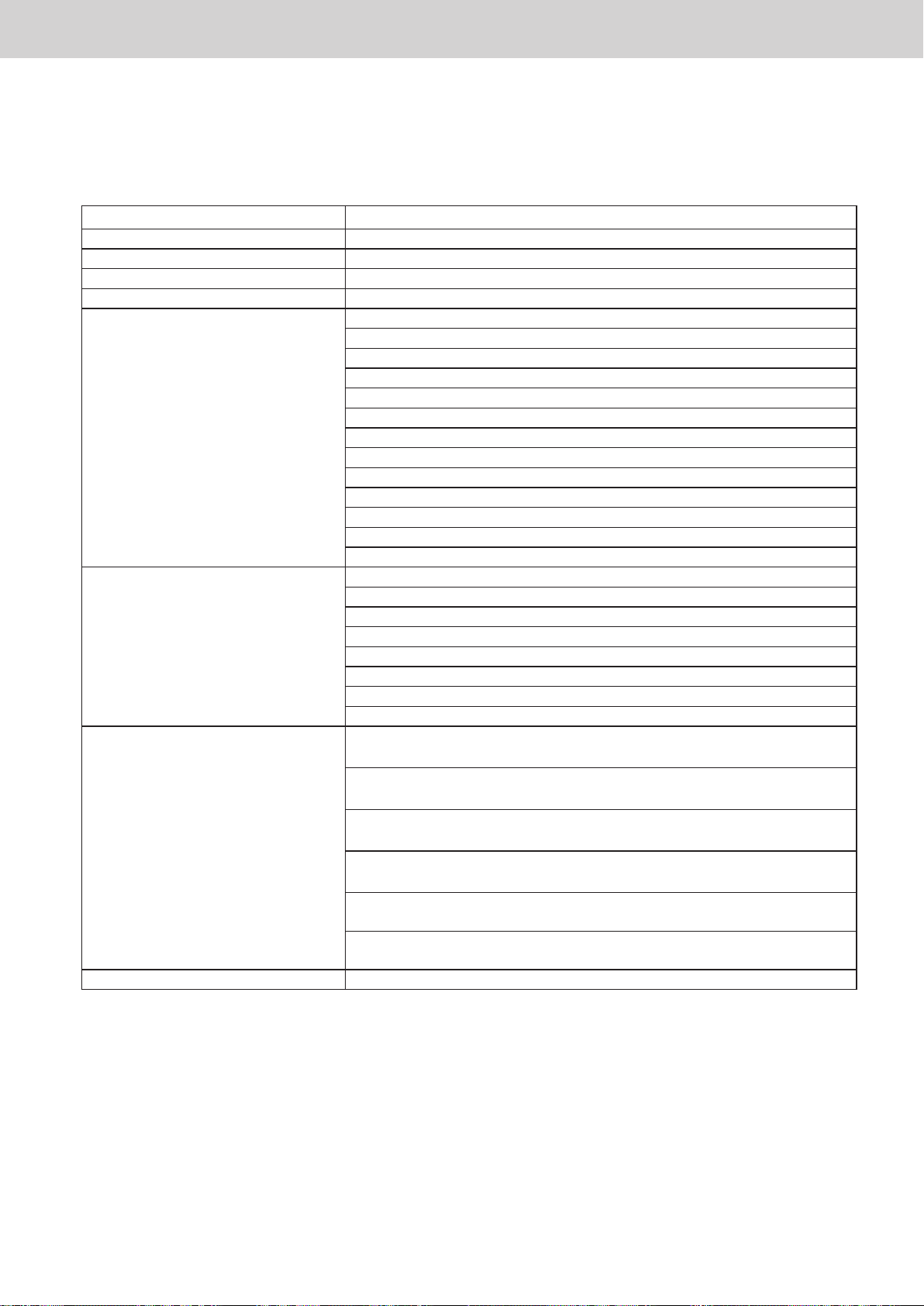
7. Advanced settings
It is possible to refer to and set detailed data using the four keys on the communication adaptor board.
Main menu Sub menu
00: Adaptor data display
01: Indoor unit data display (* 1)
02: Outdoor unit data display Connection outdoor unit address display
03: Error data display (alarm log) (* 1)
04: Adaptor data settings
05: Adaptor initial settings
06: Physical address settings and
check
07: (* 1)
01: Pulse count 1
02: Pulse count 2
03: Pulse count 3
04: Interval for regular communication 2 of air conditioner linked system 1
05: Interval for regular communication 2 of air conditioner linked system 2
06: Communication speed
07: Communication error detection interval
08: EEPROM initialisation
09: Software reset
10: No response settings
11: Delayed response settings
12: Outdoor unit maintenance data not required
13: Centralised address settings
01: Adaptor number
02: Address valid
03: Centralised equipment main-sub
04: Communication adaptor number of air conditioner linked system 1
05: Communication adaptor number of air conditioner linked system 2
06: Chattering cancel time
07: Local adaptor
08: Initial communication at power on
01: Physical address check / individual settings of air conditioner linked
system 1
02: Physical address check / individual settings of air conditioner linked
system 2
03: Clear the physical address of all indoor units of air conditioner linked
system 1
04: Clear the physical address of all indoor units of air conditioner linked
system 2
05: Automatic settings of physical address of all indoor units of air
conditioner linked system 1
06: Automatic settings of physical address of all indoor units of air
conditioner linked system 2
(* 1)
ー 18 ー
(* 1) There are currently no items to display.
Page 21
Various procedures
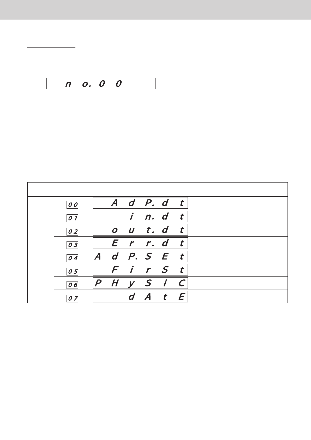
■ Main menu display
Press and hold the HOME key for 2 seconds or longer to display the menu display (level 0) screen.
•
In this status, the UP key or DOWN key can be pressed to select an item from the main menu.
On the main menu, 00 to 07 in the table below can be selected.
The main menu item number is displayed during and for 2 seconds after item change, and then the board
•
display content in the table below is displayed.
If an item (00 - 07) is selected and the SET key is pressed, the screen will shift to the detailed display screen
•
Display and settings for the communication adaptor board
for that item.
Main
menu item
↑
DOWN
UP
↓
Board display content Overview
Adaptor data display (*1)
Indoor unit data display (*1)
Outdoor unit data display
Error data display (alarm log) (*1)
Adaptor data settings
Adaptor initial settings
Physical address settings and check
Date settings and display
(* 1) There are currently no items to display.
Even during detailed settings, if you press and hold the HOME key, it will return to the main menu selection.
•
(Content in the process of being set will be discarded.)
If there is no operation for 30 seconds, the unit returns to the indication for air conditioner configuration.
•
(Content in the process of being set will be discarded.)
ー 19 ー
Page 22
Various procedures
■ (02) Outdoor unit data display
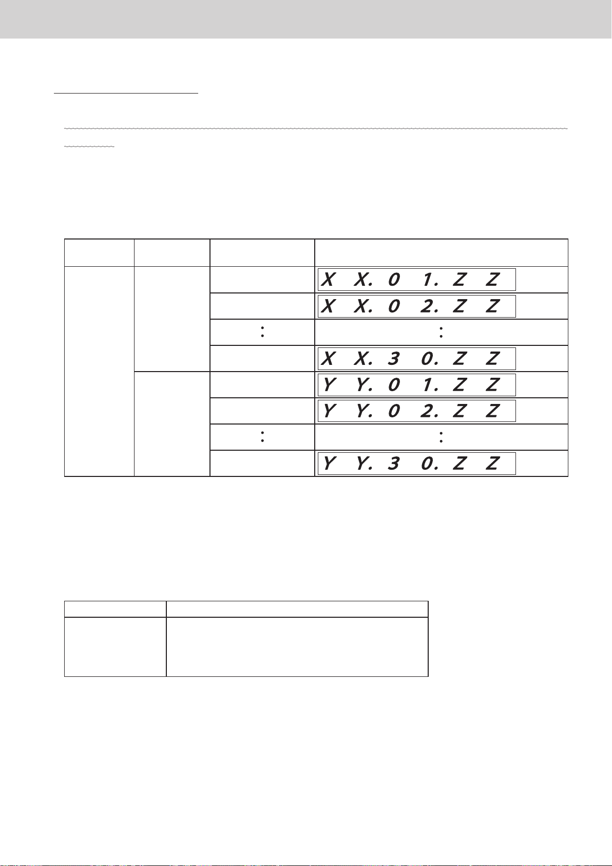
This screen is not used normally; it is used when you want to add special specifications to a particular outdoor
•
unit model.
On the main menu screen, select (02: outdoor unit data display) and press the SET key to display the data of
•
the currently connected outdoor unit.
If there is no operation for 30 seconds, the unit returns to normal display.
Display and settings for the communication adaptor board
Air conditioner
link address
XX
↑
DOWN
UP
↓
YY
ZZ is an outdoor unit model. The factory setting of the communication adaptor is 0.
•
ZZ cannot be changed by communication adaptor board operation.
Outdoor unit No. Board display
Outdoor unit No. 1
Outdoor unit No. 2
Outdoor unit No. 30
Outdoor unit No. 1
Outdoor unit No. 2
Outdoor unit No. 30
An outdoor unit with a value between 80 and 82 registered can acquire maintenance data and send it to the
•
higher software.
ZZ Outdoor unit
80
81
82
0
T-type Eco-multi
T-type W Eco-multi
T-type 3WAY
Outdoor units other than the above
ー 20 ー
Page 23
Various procedures
■ (04) Adaptor data settings
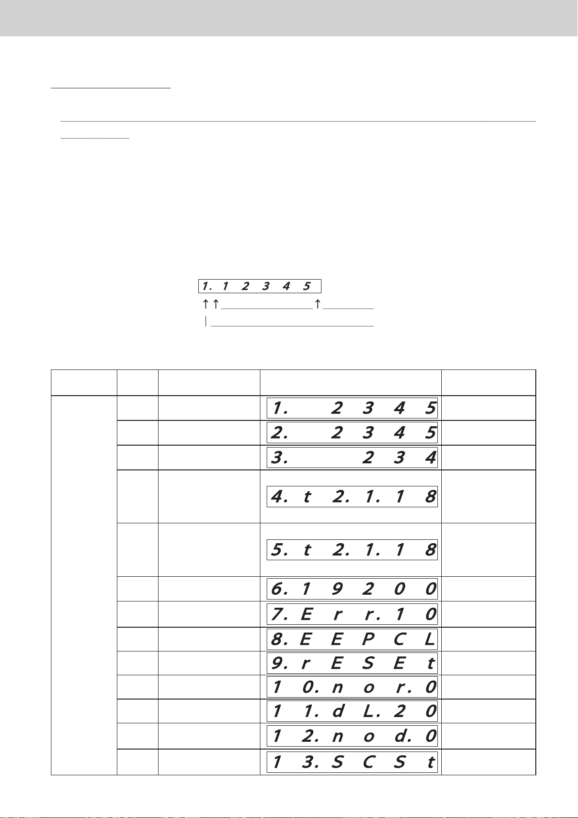
This screen is for browsing and changing the internal data of the communication adaptor and is not
•
normally used.
If (04: Adaptor settings) is selected on the main menu and the SET key is pressed, a screen with current
•
detailed information on the communication adaptor is displayed.
If there is no operation for 30 seconds, the unit returns to normal display.
Use the UP and DOWN keys to browse/set necessary data from the following items.
•
Select a data number using the UP and DOWN keys to display the data.
Data display example
Display and settings for the communication adaptor board
The characters to the right of the
point are the data.
Data number
Adaptor detailed data
•
number
↑
DOWN
Data
1 Pulse count 1
2 Pulse count 2
3 Pulse count 3
Interval for regular
4
Interval for regular
5
6 Communication speed
7
8 EEPROM initialisation
Communication error
Item Display Remarks
communication 2
of air conditioner
linked system 1
communication 2
of air conditioner
linked system 2
detection
2345 times
2345 times
234 times
18 minutes
18 minutes
19200 BPS
10 minutes
UP
↓
9 Reset
10 No response settings
11 Delayed response 20 msec
12
13
No maintenance data
required
Central address
settings
ー 21 ー
Page 24

Various procedures
(04–01) Pulse count 1
(04–02) Pulse count 2
(04–03) Pulse count 3
Displays the current pulse count (P1, P2, P3).
•
If the pulse count value is changed, the distribution function of the Intelligent Controller will not operate properly.
•
[How to change]
1 Press and hold the SET key for at least 1 second and the pulse count value blinks.
2 Press the UP or DOWN key to change it to the pulse count value you want to set.
3 Press and hold the SET key and when the display changes from blinking to lit, the change is
completed.
Display and settings for the communication adaptor board
(Changeable range: 0 to 65535)
(04–04) Interval for regular communication 2 of air conditioner linked system 1
(04–05) Interval for regular communication 2 of air conditioner linked system 2
Displays the interval for the air conditioner regular communication 2.
•
At factory shipment, the interval for regular communication 2 is 18 minutes.
•
[How to change]
1 Press and hold the SET key for at least 1 second and the regular communication interval (minutes)
2 Press the UP or DOWN key to change it to the regular communication interval you want to set.
3 Press and hold the SET key. When the display changes from blinking to lit, the change is completed.
Air conditioner regular communication 2 is not performed when 0 minutes is set.
•
will blink.
(Changeable range: 0 to 99)
ー 22 ー
Page 25

Various procedures
(04–06) Communication speed
Displays the communication speed of the communication adaptor control wiring.
•
The factory setting is 19,200 BPS.
•
The following BPS can be selected.
•
1 19200 BPS ... Intelligent Controller (Do not change from this setting)
2 9600 BPS ... AMY software
[How to change]
1 Press and hold the SET key for at least 1 second and the BPS value blinks.
2 Press the UP or DOWN key to display 19200 and 9600 alternately.
3 Press and hold the SET key. When the display changes from blinking to lit, the change is completed.
4 It becomes valid after power supply restart of the communication adaptor board.
Display and settings for the communication adaptor board
(04–07) Communication error detection interval
Displays the time (minutes) until judging that a communication error with the air conditioner has occurred.
•
The factory setting is 10 minutes.
•
It can be set in the range from 0 to 99 minutes.
•
If it is set to 0 minutes, communication error detection will not be performed.
•
ー 23 ー
Page 26
Various procedures
(04–08) EEPROM initialisation
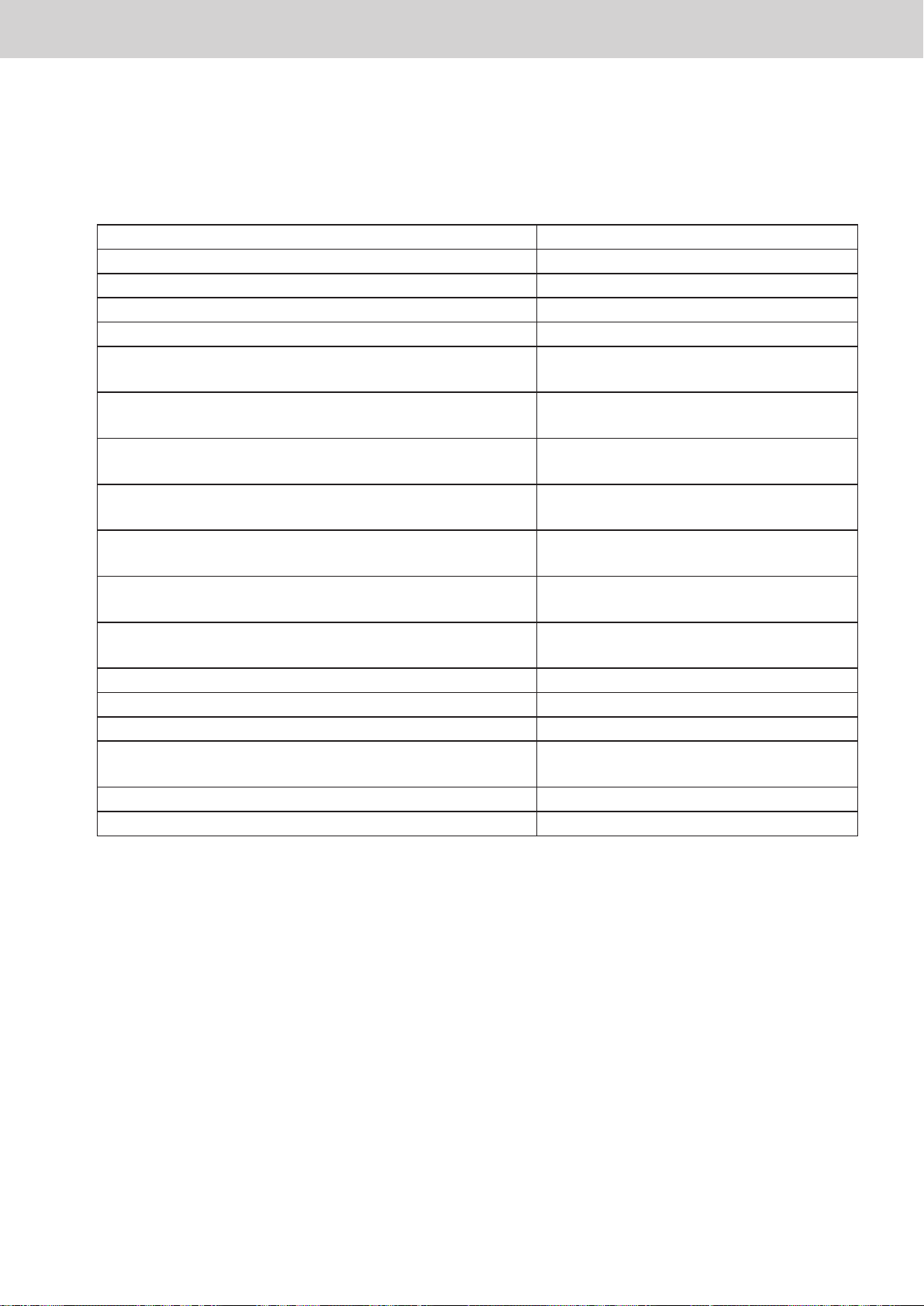
Use this to restore the EEPROM to the factory settings.
•
EEPROM initial values list
•
Pulse count 1 0
Pulse count 2 0
Pulse count 3 0
Address on air conditioner linked system 1 0x150
Address on air conditioner linked system 2 0x151
Address for air conditioner linked system 1 on communication
adaptor control wiring
Address for air conditioner linked system 2 on communication
adaptor control wiring
Presence/absence of air conditioner connection to indoor unit
or outdoor unit communication wire
Centralised equipment main-sub Air conditioner linked system 1: Main
Presence of local adaptor Air conditioner linked system 1: Yes
Check of air conditioner configuration at power on Air conditioner linked system 1: No
Response to RS485 Air conditioner linked system 1: Yes
Adaptor number 0
Pulse input chattering cancel time 100 msec
Communication speed of RS485 19200 BPS
Interval for air conditioner regular communication 2 Air conditioner linked system 1: 18 minutes
Time until air conditioner communication error detection 10 minutes
Reset count 0
Display and settings for the communication adaptor board
0x00
0x01
Air conditioner linked system 1: Yes
Air conditioner linked system 2: Yes
Air conditioner linked system 2: Main
Air conditioner linked system 2: Yes
Air conditioner linked system 2: No
Air conditioner linked system 2: Yes
Air conditioner linked system 2: 18 minutes
[EEPROM initialisation method]
1 Press and hold the SET key for at least 1 second.
2 If all segments of the 7-segment numerical display light up, EEPROM initialisation is completed.
ー 24 ー
Page 27
Various procedures
(04–09) Software reset
[Reset method]
1 Press and hold the SET key for at least 1 second.
2 Reset is completed if all segments of the 7-segment numerical display light up.
(04–10) No response settings
Sets whether to respond to request data from the communication adaptor control wiring.
•
[How to change]
1 Press and hold the SET key for at least 1 second and the setting value blinks.
Display and settings for the communication adaptor board
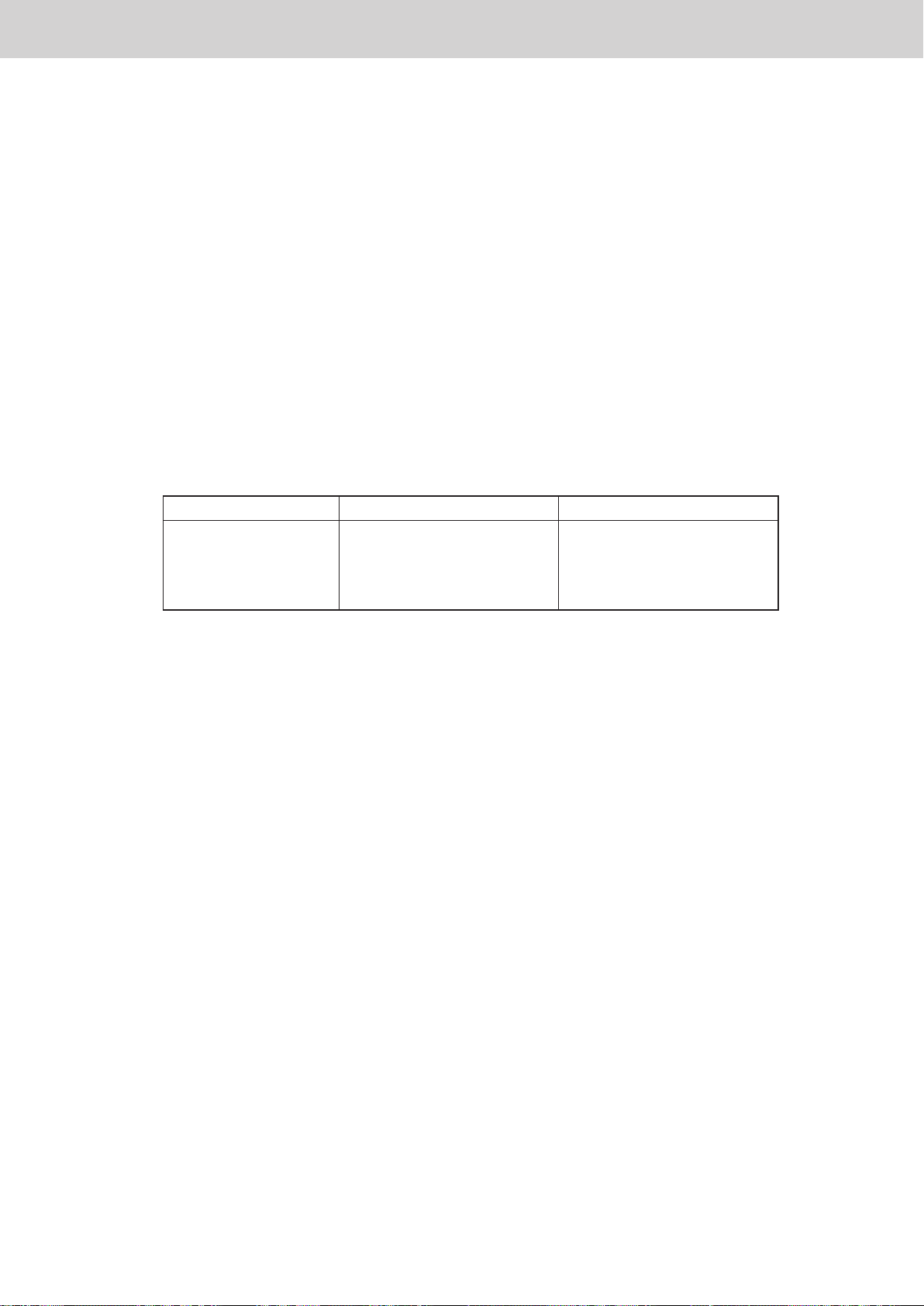
2 Press the UP or DOWN key to change the setting value in the order of 0 → 1 → 2 → 3 → 0 → · · ·.
Setting value HBS1 HBS2
0 (factory default)
1
2
3
3 Press and hold the SET key. When the display changes from blinking to lit, the change is completed.
4 Valid after power restart.
(04–11) Delayed response settings
Send response data xx milliseconds after receiving data from the communication adaptor control wiring.
•
(xx: factory default is 20 milliseconds)
Changing this setting may prevent communication with devices such as Intelligent Controller.
•
[How to change]
1 Press and hold the SET key for at least 1 second and the response delay time (milliseconds) will
Responds
Responds
Does not respond
Does not respond
Responds
Does not respond
Responds
Does not respond
blink.
2 Press the UP or DOWN key to change it to the delayed response time you want to set.
(Changeable range: 0 to 99)
3 Press and hold the SET key. When the display changes from blinking to lit, the change is completed.
ー 25 ー
Page 28

Various procedures
(04–12) Outdoor unit maintenance data not required
Use to reduce communication load by not acquiring outdoor unit data.
•
At factory shipment, it is set to acquire outdoor unit data.
•
[How to change]
1 Press and hold the SET key for at least 1 second and the rightmost digit '0' flashes.
2 Press the UP or DOWN key and '0' and '1' are alternately displayed.
0 Acquire outdoor unit maintenance data.
1 Do not acquire outdoor unit maintenance data.
3 Press and hold the SET key. When the display changes from blinking to lit, the change is completed.
(04–13) Central address settings
Display and settings for the communication adaptor board
Use this when forcibly setting a central address to an indoor unit for which a central address is not set.
•
[Central address setting method]
1 Press and hold the SET key for at least 1 second.
2 If END is displayed on the 7-segment numerical display, the setting is completed.
(It is automatically set in order of indoor unit address in the range of 1 to 64)
* The central address of already set units is not changed.
Set unused central addresses in the order of address of unconfigured units.
ー 26 ー
Page 29
Various procedures
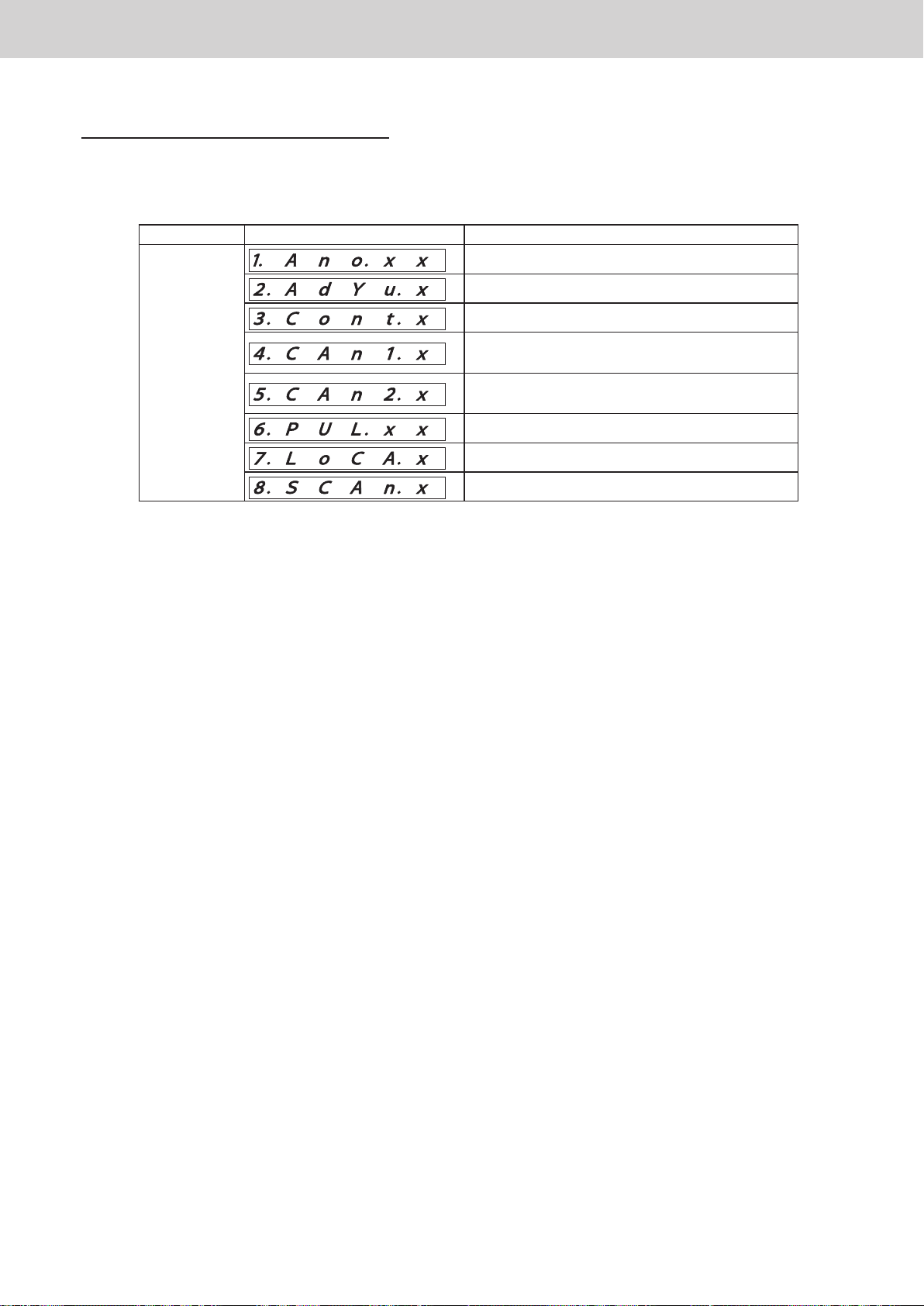
■ (05) Communication adaptor initial settings
Press the UP or DOWN key to select a function from the following options.
Display and settings for the communication adaptor board
Display Function
Adaptor number
Address valid
↑
DOWN
UP
↓
(05–01) Adaptor number
The factory default is 0.
•
It is the address on the communication adaptor control wiring.
•
Set it in the range of 0 to 15.
•
[How to change]
1
Press and hold the SET key for at least 1 second and the adaptor number blinks.
Centralised equipment main-sub
Communication adaptor number of air
conditioner linked system 1
Communication adaptor number of air
conditioner linked system 2
Chattering cancel time
Local adaptor
Initial communication at power on
2
3
Press the UP or DOWN key to display the adaptor number you want to set.
(Make sure not to duplicate addresses.)
Press and hold the SET key and when the display changes from blinking to lit, the change is
completed.
ー 27 ー
Page 30
Various procedures
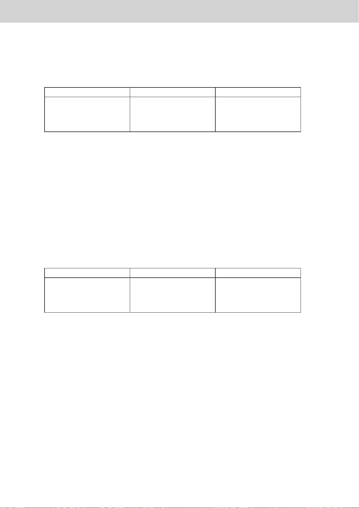
(05–02) Address valid
Set whether the air conditioner is connected to air conditioner linked systems 1 or 2.
•
Display and settings for the communication adaptor board
Address valid
0 (factory default)
1
2
3
[How to change]
1 Press and hold the SET key for at least 1 second and the address valid data blinks.
2 Press the UP or DOWN key to display the value you want to set.
(Select from 0 to 3 in the table above.)
3 Press and hold the SET key and when the display changes from blinking to lit, the change is
completed.
(05–03) Centralised device main-sub
Set main and sub of the centralised control.
•
Air conditioner linked systems 1 Air conditioner linked systems 2
Air conditioner connected
Air conditioner connected
Air conditioner not connected
Air conditioner not connected
Air conditioner connected
Air conditioner not connected
Air conditioner connected
Air conditioner not connected
Address valid
0 (factory default)
1
2
3
[How to change]
1 Press and hold the SET key for at least 1 second and the main/sub setting data of centralised control
blinks.
2 Press the UP or DOWN key to display the value you want to set.
(Select from 0 to 3 in the table above.)
3 Press and hold the SET key and when the display changes from blinking to lit, the change is
completed.
Air conditioner linked systems 1 Air conditioner linked systems 2
Main
Main
Sub
Sub
Main
Sub
Main
Sub
ー 28 ー
Page 31
Various procedures
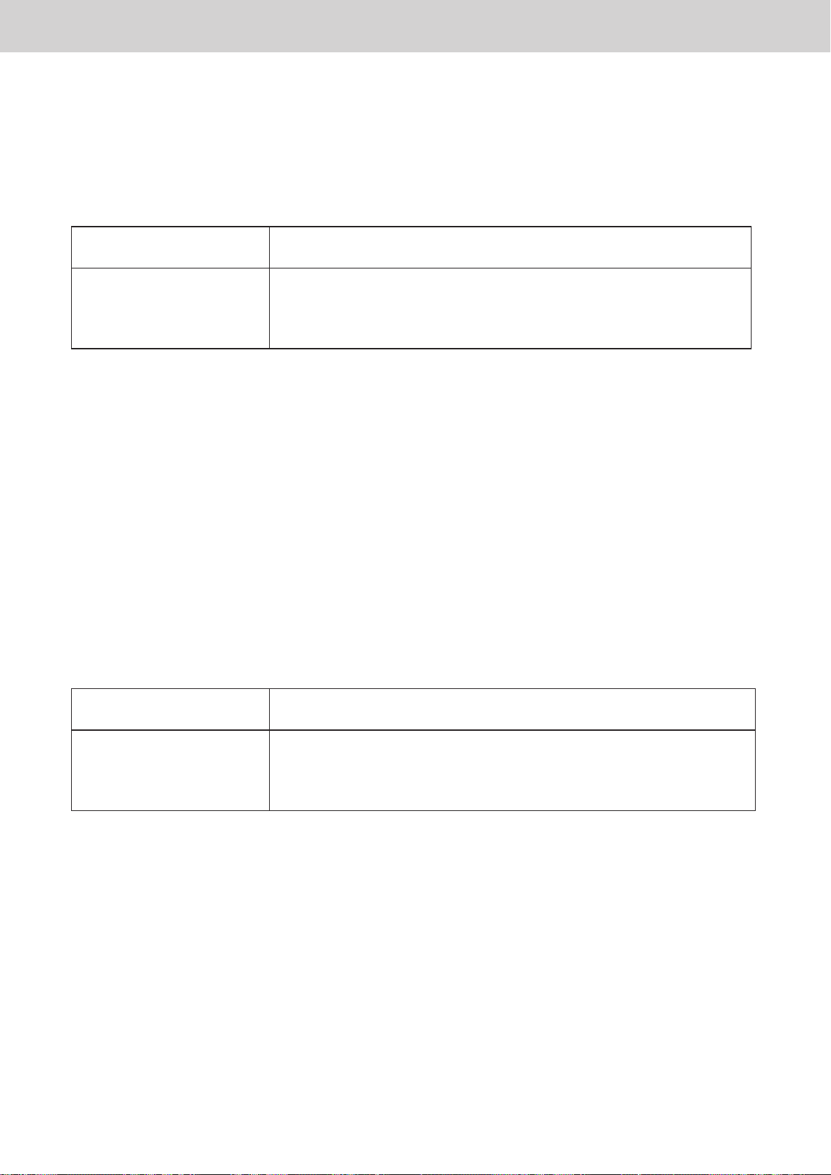
(05–04) Communication adaptor number of air conditioner linked system 1
When there are two or more communication adaptors on the air conditioner linked system, set the
•
communication adaptor number so as to avoid address duplication.
Display and settings for the communication adaptor board
Communication adaptor
number
0 (factory default)
1
:
7
[How to change]
1 Press and hold the SET key for at least 1 second and the communication adaptor number blinks.
2 Press the UP or DOWN key to display the value you want to set.
(Select from 0 to 7 in the table above.)
3 Press and hold the SET key and when the display changes from blinking to lit, the change is
completed.
(05–05) Communication adaptor number of air conditioner linked system 2
When there are two or more communication adaptors on the air conditioner link, set the communication
•
First communication adaptor to the indoor / outdoor communication wire
Second communication adaptor to the indoor / outdoor communication wire
Eighth communication adaptor to the indoor / outdoor communication wire
Contents
:
adaptor number so as to avoid address duplication.
Communication adaptor
number
0 (factory default)
1
:
7
[How to change]
1 Press and hold the SET key for at least 1 second and the communication adaptor number blinks.
2 Press the UP or DOWN key to display the value you want to set.
(Select from 0 to 7 in the table above.)
3 Press and hold the SET key and when the display changes from blinking to lit, the change is
completed.
First communication adaptor to the indoor / outdoor communication wire
Second communication adaptor to the indoor / outdoor communication wire
Eighth communication adaptor to the indoor / outdoor communication wire
Contents
:
ー 29 ー
Page 32
Various procedures
(05–06) Chattering cancel time
Set the chattering cancel time.
•
Display and settings for the communication adaptor board
Communication adaptor
number
03
10 (factory default)
[How to change]
1 Press and hold the SET key for at least 1 second and the chattering cancel time blinks.
2 Press the UP or DOWN key to display 03 and 10 alternately.
3 Press and hold the SET key and when the display changes from blinking to lit, the change is
completed.
Described in manual Capability
30 msec
100 msec
24 msec
80 msec
ー 30 ー
Page 33
Various procedures
(05–07) Local adaptor
In systems without a local adaptor, it is possible to delete the local adaptor detection during configuration
•
check.
Display and settings for the communication adaptor board
Local adaptor detection
during configuration check
0 (factory default)
1
2
3
[How to change]
1 Press and hold the SET key for at least 1 second and the data blinks.
2 Press the UP or DOWN key to display the value you want to set.
(Select from 0 to 3 in the table above.)
3 Press and hold the SET key and when the display changes from blinking to lit, the change is
completed.
(05–08) Initial communication at power on
Initial communication
at power on
0 (factory default)
1
2
3
Air conditioner linked system 1 Air conditioner linked system 2
Yes
No
Yes
No
Air conditioner linked system 1 Air conditioner linked system 2
No
Yes
No
Yes
Yes
Yes
No
No
No
No
Yes
Yes
[How to change]
1 Press and hold the SET key for at least 1 second and the data blinks.
2 Press the UP or DOWN key to display the value you want to set.
(Select from 0 to 3 in the table above.)
3 Press and hold the SET key and when the display changes from blinking to lit, the change is
completed.
ー 31 ー
Page 34
Various procedures
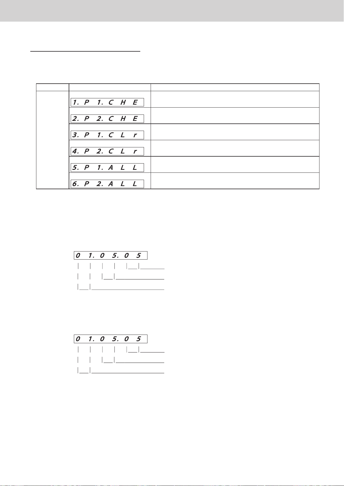
■ (06) Physical address settings and check
Normally, it is not necessary to check/set the physical address.
↑
DOWN
UP
↓
Display and settings for the communication adaptor board
Display Function
Physical address check / individual setting of air conditioner
linked system 1
Physical address check / individual setting of air conditioner
linked system 2
Clear the physical address of all indoor units of air conditioner
linked system 1
Clear the physical address of all indoor units of air conditioner
linked system 2
Automatic physical address setting of all indoor units of air
conditioner linked system 1
Automatic physical address setting of all indoor units of air
conditioner linked system 2
(06–01) Physical address check / individual setting of air conditioner linked system 1
(06–02) Physical address check / individual setting of air conditioner linked system 2
Check screen
•
Press the UP or DOWN key on the check screen to confirm the physical addresses of all indoor units.
•
Press and hold the SET key for at least 1 second on the check screen to display the individual settings screen.
•
Physical address
Indoor unit number
System address
Blinking: Physical address
Lit: Indoor unit number
Lit: System address
On the individual settings screen, press the UP or DOWN key to change it to the physical address you want to
•
set.
(Changeable range: 0 to 99)
Press and hold the SET key and when the display changes from blinking to lit, the change is completed.
•
ー 32 ー
Page 35

Various procedures
(06–03) Clear the physical address of all indoor units of air conditioner linked system 1
(06–04) Clear the physical address of all indoor units of air conditioner linked system 2
Press and hold the SET key for at least 1 second on the Physical Address Clear screen and the physical
•
address of all connected indoor units is cleared.
(06–05) Automatic physical address setting of all indoor units of air conditioner linked system 1
(06–06) Automatic physical address setting of all indoor units of air conditioner linked system 2
Press and hold the SET key for at least 1 second on the Physical Address Auto Settings screen and the
•
physical address of all connected indoor units is automatically set in the order of indoor unit address in the
range of 1 to 64.
Display and settings for the communication adaptor board
* The physical address of already-set units is not changed.
Set unused physical addresses in the order of addresses of unconfigured units.
■ (07)
There is no function for this item.
ー 33 ー
Page 36
Various procedures
Communication adaptor microcomputer rewrite procedure
Communication adaptor microcomputer rewrite procedure
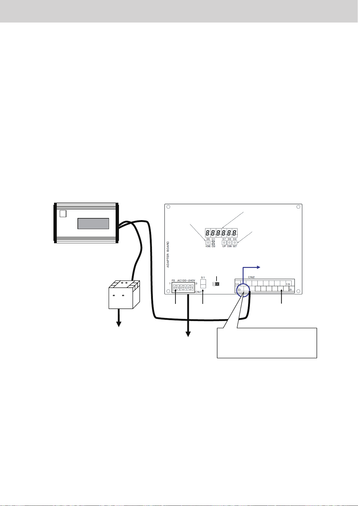
1. Things to prepare
1 Communication adaptor [CZ-CFUNC2]
2 Flash Writer 3 (software written) Factory procurement
3 12 V power supply Factory procurement
4 Dedicated wiring Factory procurement
2. Communication adaptor board software rewriting method
1 Wire as shown below and turn on the power.
Flash Writer
12 V conversion
Power supply 100 V
2 Line
Polarity: none
Outlet
HOME key
Power supply
terminal strip
Power supply
100/200 V
Communication Adaptor
7-segment numerical
display LED
UP / DOWN /
SET key
Terminating
resistanceplug
for communication adaptor
control wire
BA
CN32
Power switch Signal terminal strip
Connect to
0 and 1 (spare 0 and 2) of terminal
block 20P
(Remove other wiring.)
LINK1 (U1, U2)
Terminals (0, 1)
2 Press the button of Flash Writer 3. Software rewrite starts.
The rewrite time is 3 minutes 50 seconds. Progress is indicated as a percentage (%).
3 If [Completed!] is displayed on the Flash Writer 3 screen, rewriting is completed.
Turn off the power supply.
ー 34 ー
Page 37
Various procedures
Communication adaptor microcomputer rewrite procedure
3. How to check the version of the communication adaptor microcomputer
7-segment numerical display LED
HOME key
UP, DOWN and SET keys
Terminating resistance plug for
communication adaptor control wire
BA
CN32
terminal strip
1
Checking method using touch buttons
Power switchPower supply
Signal terminal
strip
Press the HOME key and DOWN key at the same time.
The communication adaptor version is displayed on the 7-segment numerical display.
[Example] If version 4.62
2
Checking method using power supply restart
V. 4. 6 2
Restart the power supply of the communication adaptor.
Immediately after turning on the power of the communication adaptor, all segments of the numerical display
(888888) will light up for 3 seconds, then the version will be displayed for 3 seconds.
ー 35 ー
Page 38
Various procedures
Intelligent Controller software update procedure
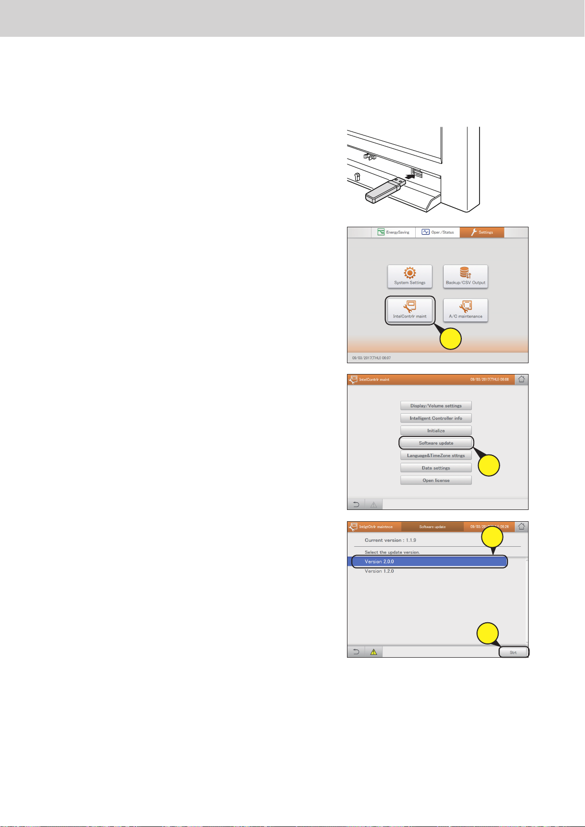
The software is updated from the USB memory device.
A service engineer should perform this operation.
1. Open the storage door and insert the USB memory
device into the USB terminal.
2. Touch [IntlgtCtrlr maintnce] in [Settings].
Intelligent Controller software update procedure
3. Touch [Software update].
zThe [Software update] screen is displayed.
4. Select the version to update (4-1), then touch [Start] (4-2).
zThe software update conrmation message is displayed.
2
3
4-
1
5. Touch [OK].
zThe conrmation message is displayed again.
zTo cancel the update, touch [Cancel].
6. Touch [Update].
zStart updating the software. During the update, the progress status is displayed.
zWhen the update is completed, the unit will restart automatically.
ー 36 ー
4-
2
Page 39
Various procedures
Replacement of SD card, and operation procedure at time of failure
Replacement of SD card, and operation procedure at time of failure
The operation procedure is different depending on the type of SD device and SD card. Always replace the SD
card according to the replacement procedure of the SD card you want to replace. If you perform SD card copy,
database switch operation, etc. without following the operation procedure, it will cause data loss or damage,
which will not be possible to recover from, so please observe caution.
●●● Caution ●●● (Cause of malfunction!)
· Do not insert or remove the SD card while working or with the power turned on.
· Be sure to turn off the power before each time the SD card is replaced (or switched between slots 1 and 2)
during operation.
· Do not forcibly remove the USB memory device except if instructed to do so on the screen. Doing so may
cause data corruption.
If you have started the Intelligent Controller normally without removing the USB memory device, please
push down on the USB removal button on the normal screen and remove it.
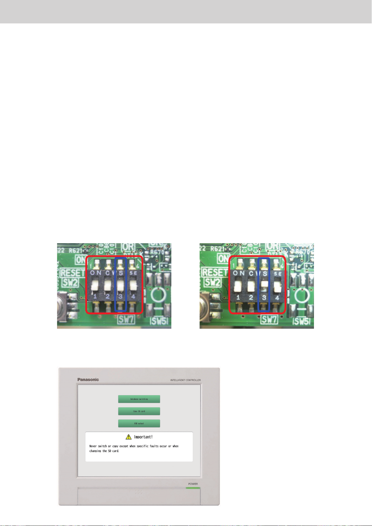
● When replacing the SD card, turn off the power of the main unit, set the DIP switch (SW7) 3 on the main board
to ON, and turn on the main unit. To return to the normal screen, turn off the main unit, set the DIP switch (SW7)
3 to OFF, and turn on the main unit.
Normal mode SD card exchange mode
When starting up with SW7 3 set to ON, the following screen starts up.
ー 37 ー
Page 40
Various procedures
● Denition of terms
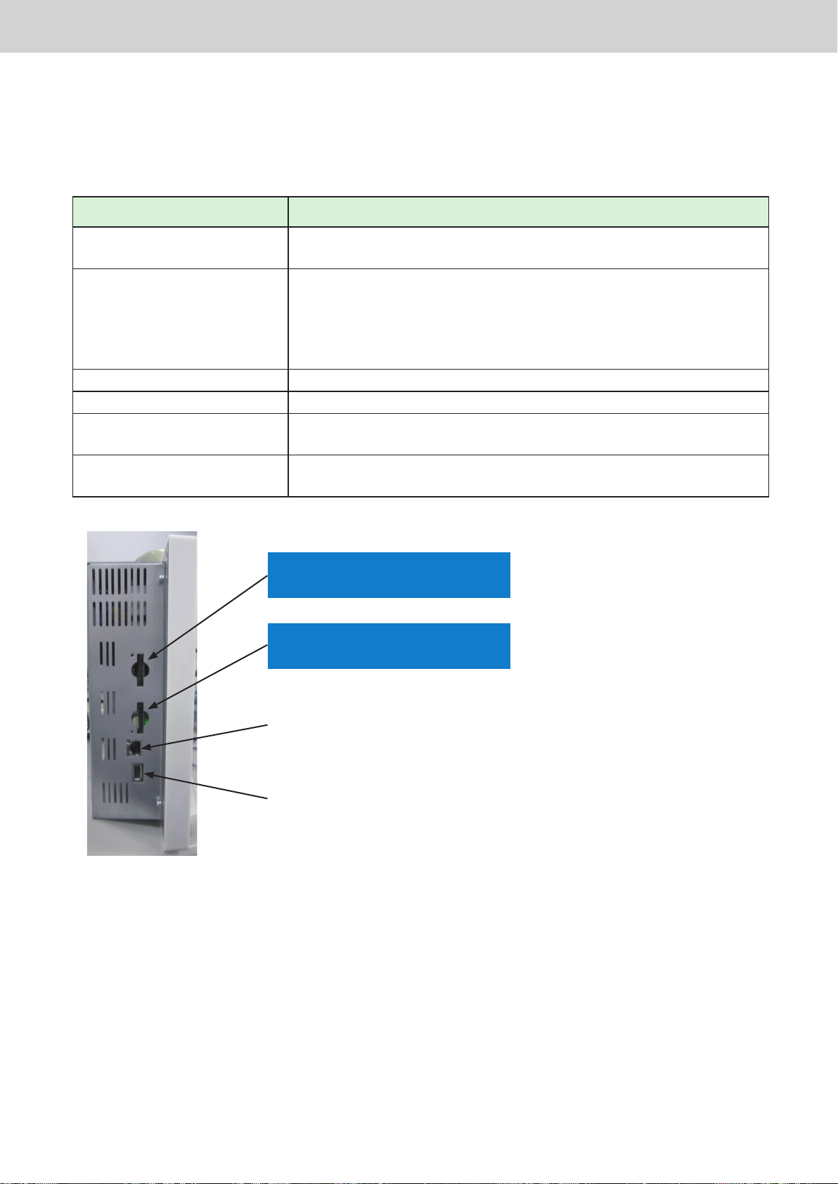
Two SD devices are built-in to the Intelligent Controller.
Since SD cards of different types (SLC/MLC) are inserted into each device, we will explain based on the following
denition of terms.
Term Description
Main SD card A high durability SLC SD card
Sub SD card A standard durability MLC SD card
SD device 1 It is used as the main SD card device.
SD device 2 It is used as the sub SD card device.
Master database This is the database mode to set the SD card inserted in SD device 1.
Replication database This is the database mode to set the SD card inserted in SD device 2.
Replacement of SD card, and operation procedure at time of failure
In normal operation, it is used as the storage location for main data.
In normal operation, it is used as the backup storage location.
* If the main SD card fails, as an emergency measure you can temporarily
operate the unit by switching the database mode so that the sub SD card is
used as the main SD card (master database). (*1)
When used as the main SD card, it is a mandatory settings mode.
When used as the sub SD card, it is a mandatory settings mode.
SD device 2: Sub SD card
Replication database (* 2)
SD device 1: Main SD card
Master database
LAN port
USB port (cannot be used)
*1: In temporary operation, insert the sub SD card that was being used in SD device 2 into SD device 1, and
switch to master database mode to operate the unit. In this case, backups will not be made because there is
no SD card inserted in SD device 2, and the unit is operated with one SD card (SD device 1 only). If the SD
card fails under temporary operation, the data cannot be restored. Temporary operation is for temporary use.
Promptly replace the service parts of the main SD card of SD device 1.
*2: The sub SD card is allowed to be used only for temporary operation. Insert the sub SD card in SD device 1
and switch the mode to master database in accordance with the operation procedure.
ー 38 ー
Page 41
Various procedures
● Description of operation procedure
After inserting the media correctly in SD device 1 and SD device 2, follow the procedure described below, and
execute by pressing the 1 “Database switch” or 2 “Copy SD card” button.
After pressing the button, execute the process according to the screen message.
Database switch
1
Change the settings so that SD device 1 (with SD card inserted) is the master database, and SD device 2 is
in replication database mode.
SD insertion (○: insert) State of the database mode of the SD card after database switch process
SD device 1 SD device 2 SD card of device 1 SD card of device 2
○ ○ Master database Replication database
○ × Master database -
× ○ - -
* Regardless of the SD card type (SLC/MLC), the database mode will be set according to the devices where they
Replacement of SD card, and operation procedure at time of failure
are inserted.
SD card copy
2
The contents of the SD card inserted in SD device 1 will be completely copied to the SD card inserted in SD
device 2.
* The unit cannot be operated with just copying. Follow the procedure to change the database mode correctly
using the “database switch” process.
USB output (* not used in the SD card exchange process)
3
Back up (extract) only the master database of SD1 onto the USB memory device.
* Insert the USB memory device correctly in the front USB terminal. (The side USB port can not be used)
* You can not restore from this backup (extracted) database le.
* Do not use this output function unless it is necessary.
ー 39 ー
Page 42
Various procedures
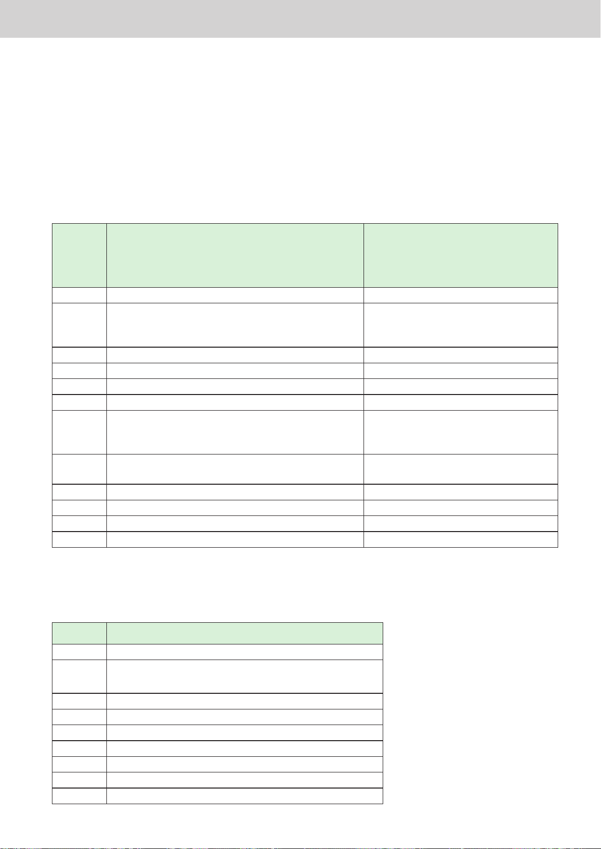
Properly execute the procedure according to the SD card you want to replace, based on the operation procedure
of 1 to 2 in the operating procedure description.
Power ON/OFF】: Turn on/off the power of the Intelligent Controller unit
【
DPSW ON/OFF】: Turn on/off DIP switch (SW7) 3
【
New SD card
【
● Procedures for failure and replacement of the main SD card
For replacement, a main SD card (SLC) as a service part is required. In the following table, it is described as “new
SD card”.
: A special formatted SD card which can be obtained as a service parts. Commercial SD
】
Replacement of SD card, and operation procedure at time of failure
cards cannot be used.
Procedure For main SD card failure/replacement (after acquiring
service parts)
When returning from temporary operation of the sub SD
card to normal operation (after acquiring service parts)
1 Power OFF Power OFF
Insert the SD cards as follows.
2
3 DPSW ON DPSW ON
4 Power ON Power ON
5 SD card copy (procedure 2) Database switch
6 Power OFF Power OFF
7
8
9 Database switch (procedure 1)
10 Power OFF
11 DPSW OFF
12 Power ON (normal startup)
* The sub SD card will be used from the backup point (once a day).
SD device 1: SD card of SD device 2
SD device 2: New SD card
Insert the SD cards as follows.
SD device 1: New SD card
SD device 2: SD card of device 2
Power ON Power ON (normal startup in temporary
Temporary operation with sub SD card
Insert the SD cards as follows.
SD device 1: SD card of SD device 2
SD device 2: None
DPSW OFF
operation)
● Procedure for failure and replacement of the sub SD card
A sub SD card (MLC) as a service part is required. In the following table, it is described as “new SD card”.
Procedure For sub SD card failure/replacement
1 Power OFF
2
3 DPSW ON
4 Power ON
5 SD card copy (procedure 2)
6 Database switch (procedure 1)
7 Power OFF
8 DPSW OFF
9 Power ON (normal startup)
SD device 1: SD card of SD device 1
SD device 2: New SD card
ー 40 ー
Page 43
Procedure for replacing touch panel LCDVarious procedures
㩷㩷㩷㩷㩷 㩷
Procedure for replacing touch panel LCD
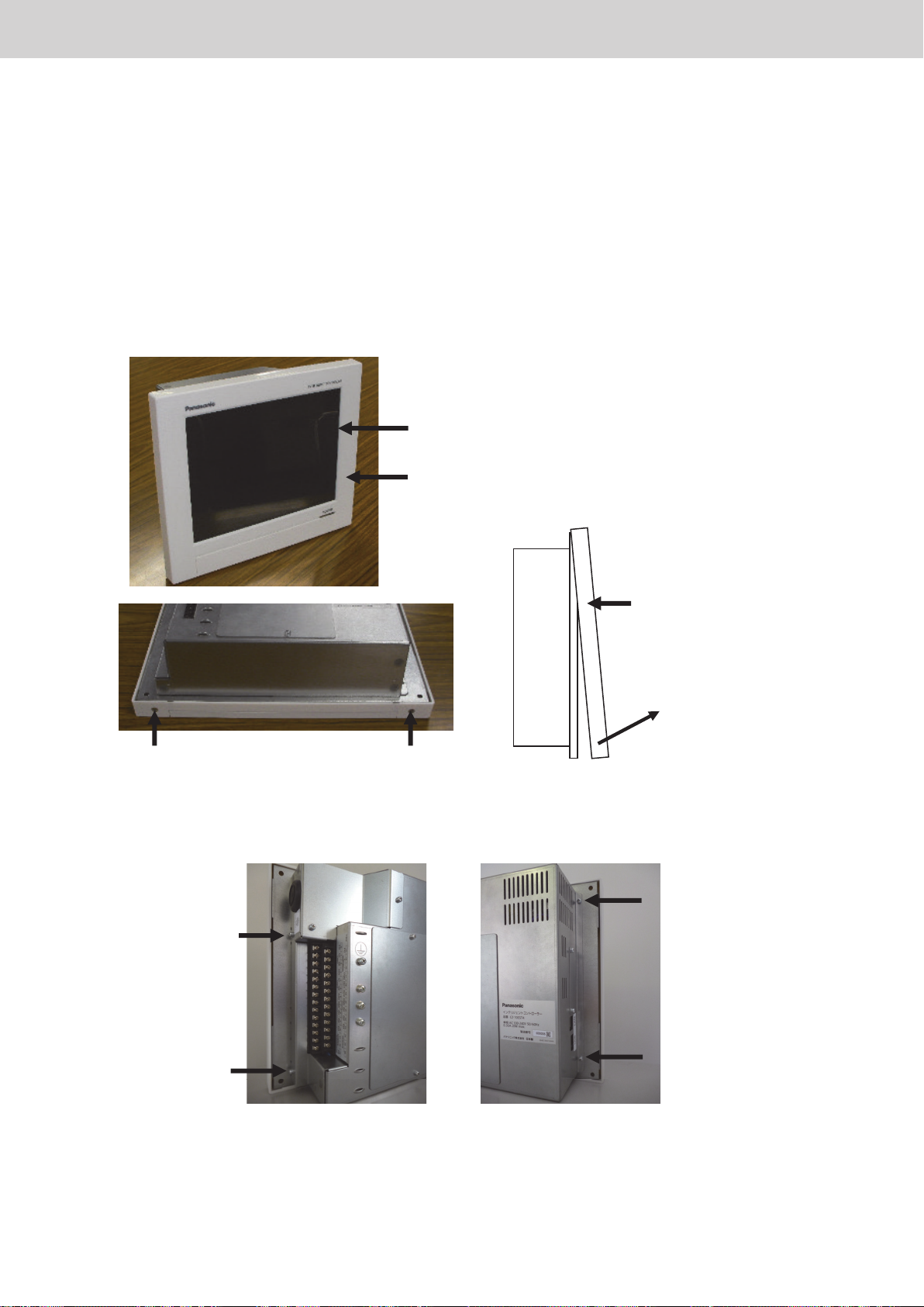
Procedure manual for replacing the LCD panel with touch panel of the Intelligent Controller.
* Remove the power cable, etc., and do the work with the main unit removed from the incorporated control
board, etc.
* The touch panel is integrated with the LCD.
Remove the resin front panel. (Two countersunk screws)
1
As shown in the figure below, remove the two screws on the bottom left and right sides, and lift the bottom
side to remove the front panel.
LCD panel
Front panel
㩷㩷㩷
Front panel
㩷
Screw Screw
Remove the sheet metal on the back of the main unit. (Four screws)
2
Remove the four screws (left and right sides) of the sheet metal as shown in the figure below.
(Bottom surface of the
main unit)
Screw
Lift the lower side forward
to remove
Screw
Screw
Screw
ー 41 ー
Page 44
Procedure for replacing touch panel LCDVarious procedures
㩷
㩷
㩷
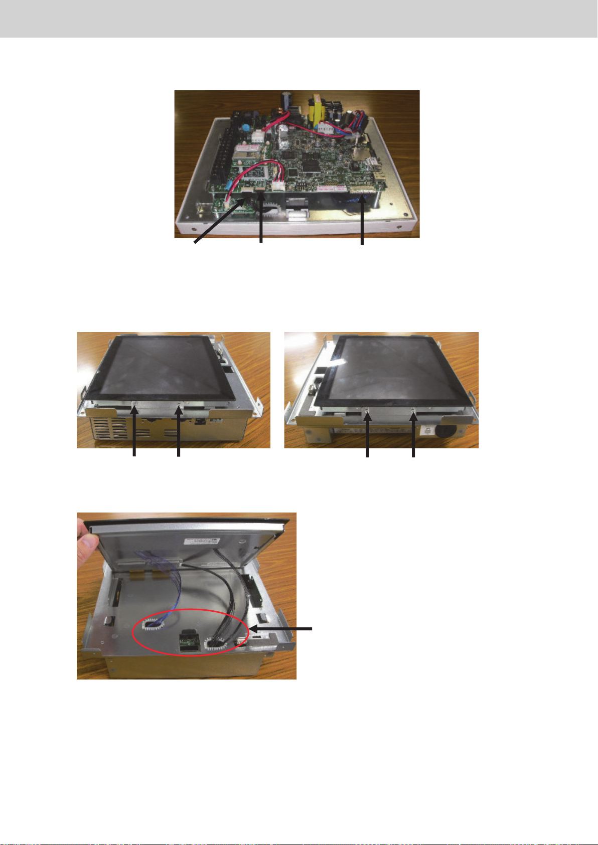
Remove the LCD and touch panel connectors. (Three places)
3
Cables for
touch panel
Temporarily mount the sheet metal on the back of the main unit (screw fastening not required), remove the
4
screws on the sides of the LCD with the LCD facing up. (Four places)
Cables for
LCD backlight
Cables for LCD
㩷㩷
Screw ScrewScrew Screw
Lift the front side of the LCD forward and pull out the three cables.
5
Pull out the three cables
ー 42 ー
Page 45
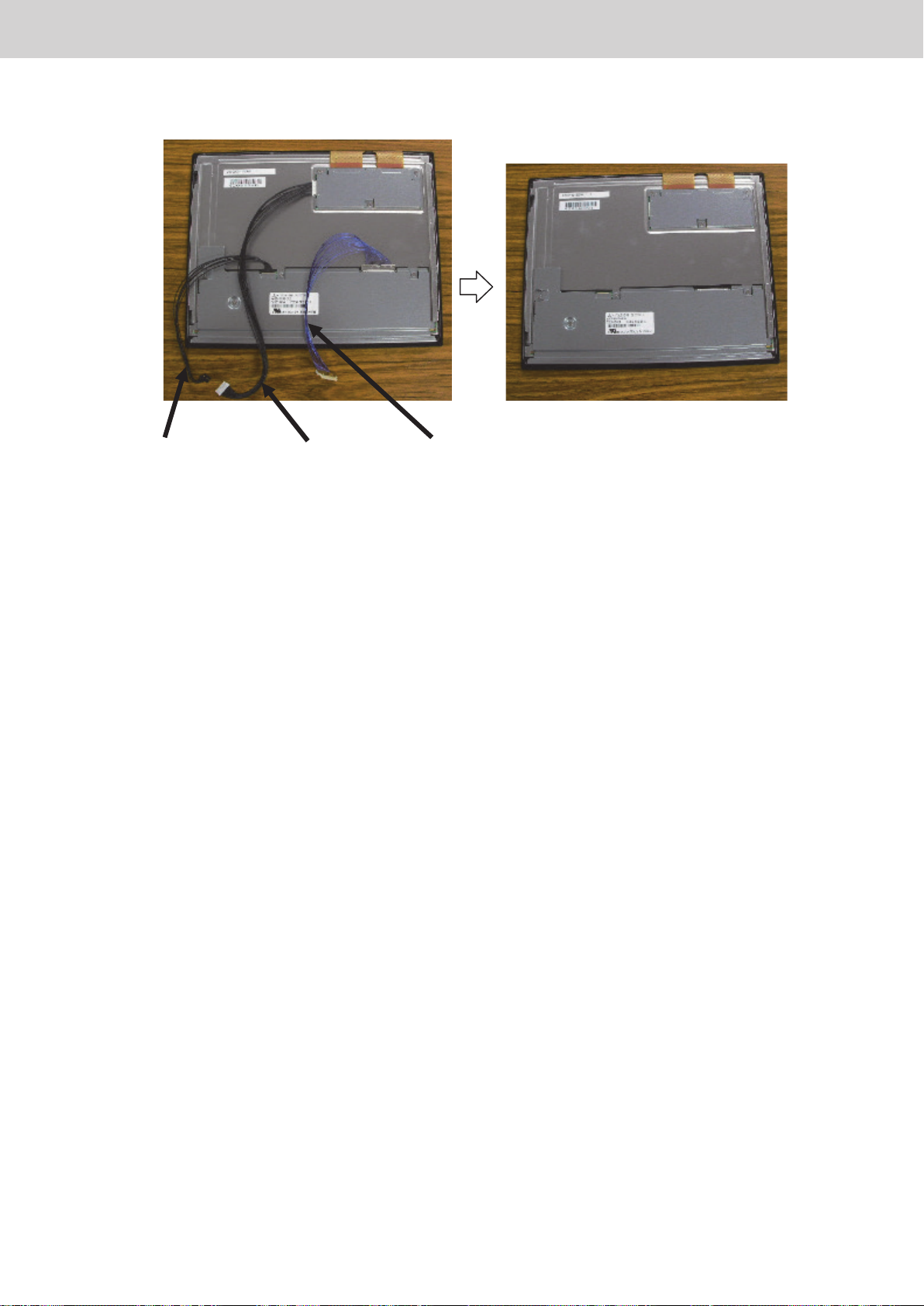
Remove the following cables and replace the LCD.
6
Procedure for replacing touch panel LCDVarious procedures
Cables for
LCD backlight
Assembly is done by reversing the above procedure.
7
* Pass the cable through the hole in the original sheet metal.
* Be careful that the cable does not get caught during assembly.
Cables for
touch panel
Cables for LCD
ー 43 ー
Page 46

Procedure when adding/removing a unitVarious procedures
Procedure when adding/removing a unit
When adding, removing or relocating units managed by the Intelligent Controller (indoor units,
outdoor units, and local adaptors), problems may occur such as with centralised control and
air conditioning distribution calculation unless the settings and registration are changed for the
Intelligent Controller.
Take adequate care, since the necessary work varies case by case.
* In the linked system (or adaptor system), if you simply move the physical installation location,
there is no need to reapply the settings.
■
Flow of overall work (*1)
First of all, distribution calculation is done in the state before work.
(Specify the date of the current day as the end day using [Oper./Status] → [Accumult/Distrib]
→ [Distribution data].)
Add, remove, and relocate the units, complete necessary address settings, etc. and conrm
normal operation as an air conditioner
* The [Cong. change] warning may be displayed on the Intelligent Controller screen,
but do not operate the screen until the air conditioner work is complete.
↓
After completing the work on the air conditioner, perform [Check conguration] with the
Intelligent Controller
↓
After a short period of time, [Cong. has been chngd] is displayed.
↓
When prompted with [Conrm conguration?], select [Begin cong]
↓
When the check conguration process is complete, conrm the indoor address display
(On the [Settings] / [System settings] / [I/D unit settings] screen, etc.)
↓
Make necessary changes to settings, such as the area settings and unit name according to
the modication work.
Be sure to set the central address for added units
↓
Make backup and end (1 Insert USB memory device in USB terminal → 2 [Backup/CSV
output] in [Settings] → 3 [Backup] → 5 Save to USB memory device)
* The number is the number of the Intelligent Controller operating instructions.
*1
If distribution calculation is required:
In cases where distribution processing is affected by the addition, removal, or relocation of
indoor units, distribution calculation is always required.
For example,
· Addition of indoor units to area
· Removal of indoor units from area
· Relocation of indoor units between areas
· Partition change of area
On the other hand, distribution processing may not be affected in some cases.
For example,
· Addition/removal/relocation of units not subject to distribution (shared parts, etc.)
· Addition/removal/relocation of units in vacant rooms (area not registered)
· Physical relocation within an area (there is also no [Cong. change])
In such cases, distribution calculation is not required.
ー 44 ー
Page 47

Various procedures
Procedure when entering or leaving an area mid-period
Procedure when entering or leaving an area mid-period
If occupants move into or move out from an area while doing air conditioning distribution or charge
distribution, unless the work for that is performed, note that it will affect the distribution of the other
areas.
■ Ideally
Ideally, occupants should move in or move out the next day after the cutoff day (that is, after the
cutoff is over) and then the settings work for addition or removal of area should be performed
immediately.
If occupants move in or out without waiting for the cutoff day, perform the work as follows.
■ In the case that occupants move out from the area mid-period
(1) Calculate the distribution on the day of moving out. (Specify the date of the current day as the
end day using [Oper./Status] → [Accumult/Distrib] → [Distribution data].)
(2) For the area from which occupants have moved out, process the billing with the usage
amount based on the cutoff data.
(3) Delete the area from which occupants have moved out from the settings of the area number,
area name, distribution group, etc.
(4) Wait for the normal cutoff day and calculate the monthly usage amount by summing up the
data for two times in each area together with the distribution calculation of (1) for that month
only.
* If it is obvious that nobody will move into the vacated area by the next cutoff day (such that
the air conditioners will not be used), it is possible to wait until the next cutoff day while
keeping the last billing processing on hold, then carry out billing processing in the same way
as other areas according to the cutoff day. Then perform (3) above.
■ In the case that occupants move into the area at the period
(1) Calculate the distribution on the day before moving in. (Specify the date of the current day as
the end day using [Oper./Status] → [Accumult/Distrib] → [Distribution data].)
(2) On the day of moving in, perform the settings for the area number, area name, distribution
group, etc. for the area.
(3) Then wait for the normal cutoff day, and perform billing processing for the area that occupants
have moved into part way through according to the contents of the cutoff data.
For other areas, calculate the monthly usage amount by summing up the data for two times in
each area together with the distribution calculation of (1) for that month only.
* If it is obvious that nobody has occupied the area at least from the previous cutoff day until the
present day (the air conditioners have not been used), it is possible not to perform the manual
cutoff in (1).
■ Do not forget to remove from the [Distrib. Grp.] settings for indoor units in rooms of areas which
are not occupied.
If you remove them from the distribution group, it is no problem to register them as areas with area
names such as “vacant room”.
In addition, it is recommended that you set [ON/OFF Prhbt.] for the remote controller of vacant
rooms.
* If you leave a vacant room in the distribution group and the indoor unit is operated, distribution to
that vacant room will occur.
Also, if load distribution is used, the standby power will be counted even in the OFF state, so the
distribution will not be 0%.
ー 45 ー
Page 48
Operating Instructions Intelligent Controller
Operating Instructions
Intelligent Controller
Model No. CZ-256ESMC3
ENGLISH
Before operating the unit, read these operating instructions thoroughly and keep them for future reference.
Installation Instructions
Separately Attached.
CV6233334158
Panasonic Corporation
http://www.panasonic.com
Panasonic Corporation
1006 Kadoma, Kadoma City, Osaka, Japan
Intelligent Controller (CZ-256ESMC3)
●
ー 46 ー
Page 49
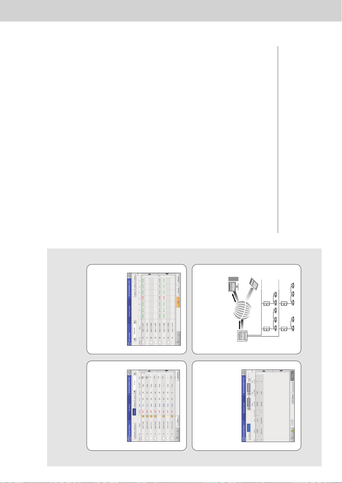
Operating Instructions Intelligent Controller
2
Features
This unit is a centralized air conditioning management system designed for use with precision air
conditioning systems (PAC, air conditioning systems for ofces and shops, and multi-unit systems for
buildings) and gas heat pump (GHP) air conditioners.
z With one of these units you can connect and control up to 128 indoor units (2 systems of 64 units each) and 60 outdoor units (2 systems of
30 units each).
z By connecting a communication adaptor this can be increased to 256 indoor units and 120 outdoor units.
z The unit is equipped with a 10.4-inch TFT colour touch panel display (1024 x 768 dots), enabling control by almost anyone.
Operation and status
P.23
You can check to operational status (ON/OFF, operating
mode, alarms, etc.) of all indoor units and outdoor units in
real time.
You can also select indoor units to change their settings.
Distributing air conditioner
energy
P.71
You can view cumulative operating times for indoor units,
engine operating times for outdoor units, and operation
cycles in a list. (Cumulative values)
Using these data, you can calculate the distribution ratio of
electricity or gas consumed for air conditioning and volumes
used (kWh, m
3
) per indoor unit or in an area, then show
these calculations in a list.
Operation scheduling
P.39
You can register daily operation schedules (ON/OFF time,
operating modes, set temperatures, etc.) for individual
indoor units or groups of indoor units.
Operations can be schedule for up to 2 years in advance.
Remote control
P.122
The LAN terminal on this unit enables you connect it to a
network.
Connecting to Internet will enable you to operate the unit
and check the status using a PC from a remote location.
3
Contents
Features ……………………………………………………………… 2
Contents ……………………………………………………………… 3
Simple guide to features …………………………………………… 4
Safety precautions ………………………………………………… 5
Operating precautions ……………………………………………… 6
Installation precautions……………………………………………… 6
System conguration ……………………………………………… 7
Explanation of terms ………………………………………………… 8
The Energy Saving function ……………………………………… 9
Energy navigation function ……………………………………… 11
Preparations before changing settings 12
Part names ………………………………………………………… 13
Operations on this unit …………………………………………… 14
Menu list …………………………………………………………… 18
Initial settings ……………………………………………………… 20
Input of the admin number (password) ………………………… 22
Check the status of air conditioning units 23
Checking the settings on the indoor unit ……………………… 24
Changing the settings on the indoor unit ……………………… 26
Checking the operational status of indoor units ……………… 28
Checking the operational status of the outdoor unit ………… 32
Checking on current alarms ……………………………………… 35
Setting a schedule 39
Schedule setting ow …………………………………………… 40
Setting a schedule ………………………………………………… 43
Allocating a schedule to a calendar …………………………… 49
Checking the future schedule and past performance ………… 53
Temporarily modifying or adding a schedule ………………… 55
Checking the alarm logs and operation/status change
logs 57
Checking the alarm logs ………………………………………… 58
Checking the operation/status change log in a list …………… 61
Check accumulated values 64
Checking the list of accumulated values on the indoor unit … 65
Checking the list of accumulated values on the outdoor unit … 67
Checking the list of accumulated values on a pulse meter … 69
Checking distribution data 71
Checking distribution data in a list ……………………………… 72
Settings for energy saving 76
Automatically return to set temperatures
[Set temp. auto return] ……………………………………… 77
Automatically stopping restarts [Unattended auto shutoff] …… 80
Restricting the range of set temperatures
[Set temperature range limit] ……………………………… 83
Restricting operating capacity according to the time slot
[Energy saving timer]/[Efcient operation setting] ………… 85
Reducing the noise of outdoor units [Out unit silent setting] … 87
Demand settings on the indoor unit
[I/D unit demand settings] …………………………………… 89
Demand settings on the outdoor unit
[O/D unit demand settings] ………………………………… 92
Suppressing the consumption of electricity/gas
[Demand/peak shaving settings]/[Peak cut settings] …… 94
Control operation at regular intervals [I/D unit cyclic] ………… 97
Control operation at regular intervals [O/D unit cyclic] ………101
Registering demand point input [Register demand point] ……104
Displaying data in graphs 105
Graph display function …………………………………………… 106
Graphing operating times and energy usage ………………… 109
Graphing temperature changes ………………………………… 11 3
Setting items freely ……………………………………………… 116
Perform remote operation of the unit over a network 122
Setting the network ……………………………………………… 123
Setting the users ………………………………………………… 125
Control remotely …………………………………………………128
Backing up/restoring data 129
Backing up data …………………………………………………… 130
Restoring data …………………………………………………… 132
Outputting settings as a CSV le ………………………………134
Inputting settings as a CSV le ………………………………… 136
Saving automatically generated les ……………………………138
Conguring the system 140
Basic settings on the indoor unit ………………………………… 141
Basic settings on the outdoor unit ………………………………145
Basic settings for distribution calculation ………………………148
Changing the name of the schedule group …………………… 151
Changing the name of the area group ………………………… 153
Changing the name of the distribution group ………………… 155
Basic settings for the pulse meter ………………………………158
Set the distribution mode …………………………………………160
Set the units for electricity/gas charges ………………………… 161
Linked control of air conditioning units …………………………162
Conguring outgoing mail ………………………………………168
Registering a communication adaptor ………………………… 170
Maintenance settings 172
Setting the screen display and volume for this unit ……………173
Register the contacts for servicing for this unit………………… 174
Update the software ……………………………………………… 175
Initialising the unit and setting log levels ……………………… 176
Setting the date and time ………………………………………… 178
Setting the language and time zone ……………………………179
Running a test operation ………………………………………… 181
Setting communications with air conditioning units ……………184
Ignoring alarms from the units …………………………………… 186
Appendix 187
Number and letter input ………………………………………… 188
Connections with external signals ……………………………… 190
Methodology for calculating distributions ………………………191
Things you should know …………………………………………195
Troubleshooting …………………………………………………… 200
Cautions when cleaning and maintaining ……………………… 201
Trademark and indemnity ………………………………………202
Specications ……………………………………………………… 203
z Read the Operating Instructions carefully for safe use. This manual describes the Operating Instructions of the intelligent controller. Read this
manual as well as operating instructions supplied with indoor units and outdoor units.
z Be sure to read the “Safety precautions” (P.5) before using.
z Keep this manual with operating instructions supplied with indoor units and outdoor units in a safe place.
z Be sure to keep this manual in a place easily accessible by users. In the case of user change, be sure to give this manual to the new user.
NOTICE
The English text is the original instructions. Other languages are translation of the original instructions.
ー 47 ー
Page 50
Operating Instructions Intelligent Controller
4
Simple guide to features
This guide only shows the main features.
Operations on the indoor unit
What you want to do Title Page
To change the settings on the indoor unit Changing the settings on the indoor unit 26
To change the operating mode Changing the settings on the indoor unit 26
To change the set temperature Changing the settings on the indoor unit 26
To reset the lter sign Checking the settings on the indoor unit 25
To change the airow direction and fan speed Changing the settings on the indoor unit 26
To prevent operation by remote controllers Changing the settings on the indoor unit 26
Checking the operating status
What you want to do Title Page
To check the operational status of the indoor units you are managing Checking the operational status of indoor units 28
To check the current alarms Checking on current alarms 35
To check alarm history Checking the alarm logs 58
To check the current or past cumulative times Checking the list of accumulated values on the indoor unit 65
To check the current or past distribution ratios Checking distribution data in a list 72
Settings
What you want to do Title Page
To change the name of an indoor unit Basic settings on the indoor unit 141
To change the name of the area group Changing the name of the area group 153
To adjust the date or time Setting the date and time 178
To operate an indoor unit according to a schedule Setting a schedule 39
To adjust the brightness of the screen Setting the screen display and volume for this unit 173
To adjust the sound of the buzzer Setting the screen display and volume for this unit 173
Miscellaneous
What you want to do Title Page
To backup data (settings, cumulative values, distribution data, etc.) to a USB
memory device
Backing up data 130
To show the operating times, temperature changes, and other information in
graphs
Displaying data in graphs 105
5
Safety precautions
WARNING CAUTION
This symbol refers to a hazard or unsafe
practice which can result in severe personal
injury or death.
This symbol refers to a hazard or unsafe
practice which can result in personal injury or
product or property damage.
Matters to be observed Prohibited matters
WARNING
Do not use this appliance in a potentially explosive atmosphere.
In case of malfunction of this appliance, do not repair by yourself. Contact the sales or
service dealer for repair.
In case of emergency, remove the power plug from the socket or switch off the
circuit breaker or the means by which the system is isolated from the mains
power.
CAUTION
This appliance is intended to be used by expert or trained users in shops, in light
industry and on farms, or for commercial use by lay persons.
This appliance can be used by children aged from 8 years and above and persons with
reduced physical, sensory or mental capabilities or lack of experience and knowledge
if they have been given supervision or instruction concerning use of the appliance in a
safe way and understand the hazards involved.
y Do not operate with wet hands.
y Do not wash with water.
ー 48 ー
Page 51
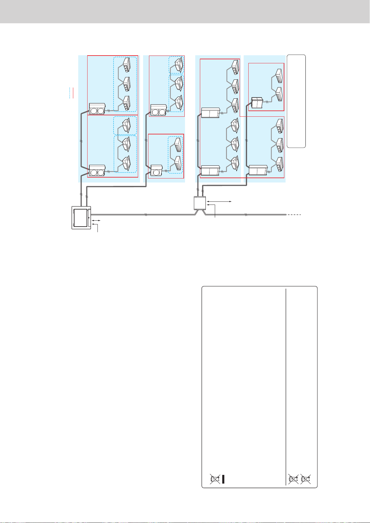
Operating Instructions Intelligent Controller
6
Operating precautions
z Do not use in the following locations
y Where ammable gases, etc. may leak
y Near the ocean or other areas with a lot of salt
y In areas where sulphurous gases occur such as natural spa areas
y In places where there may be airborne water or oil (including machinery lubricants, etc.) or steam
y Where there are large uctuations in voltage
y Where machinery emitting electromagnetic waves are located
y Where there may be airborne organic solvents
z Do not apply strong shocks
(This may cause malfunction)
z Do not use heaters near the controller
(This may cause deformation or discolouration)
z Do not use hard or pointy objects
(This may cause scratches or malfunction)
z Do not hit the touch panel or push on it too strongly
(This may cause malfunction)
Installation precautions
z Do not install in locations with high humidity, lots of oil, vibrations, where direct sunlight can reach the unit, or near sources of
heating
(This may cause malfunction)
z Do not install in noisy locations
(This may cause incorrect operation)
z Install at least 1 m away from TV, radio, PC. etc.
(To prevent fuzzy images or noise)
Information for Users on Collection and Disposal of Old Equipment and Used Batteries
These symbols on the products, packaging, and/or accompanying documents mean that used electrical and
electronic products and batteries should not be mixed with general household waste.
For proper treatment, recovery and recycling of old products and used batteries, please take them to applicable
collection points, in accordance with your national legislation and the Directives 2002/96/EC and 2006/66/EC.
By disposing of these products and batteries correctly, you will help to save valuable resources and prevent any
potential negative effects on human health and the environment which could otherwise arise from inappropriate
waste handling.
For more information about collection and recycling of old products and batteries, please contact your local
municipality, your waste disposal service or the point of sale where you purchased the items.
Penalties may be applicable for incorrect disposal of this waste, in accordance with national legislation.
For business users in the European Union
If you wish to discard electrical and electronic equipment, please contact your dealer or supplier for further
information.
[Information on Disposal in other Countries outside the European Union]
These symbols are only valid in the European Union. If you wish to discard these items, please contact your local
authorities or dealer and ask for the correct method of disposal.
Pb
Note for the battery symbol (bottom two symbol examples):
This symbol might be used in combination with a chemical symbol. In this case it complies with the requirement
set by the Directive for the chemical involved.
7
System conguration
The following is an example of a system conguration.
Intelligent Controller
Communication
adaptor
Inter-unit control wiring
(no polarity)
Inter-unit control wiring
(no polarity)
Pulse meter x 3
Pulse meter x 3
Inter-unit control
wiring (no polarity)
Area group (P.8)
Distribution group (P.8)
Inter-unit
control
wiring (no
polarity)
Linked systems #1
Linked systems #2
Linked systems #3
Linked systems #4
Communication adaptor
control wiring (RS-485
(polarity present))
Communication adaptor
control wiring (RS-485
(polarity present))
Signal input x 3
Signal output x 2
Signal input x 3
Signal output x 2
Indoor units: 256 units (64 units x 16 systems)
Outdoor units: 120 units (30 units x 16 systems)
Communication adaptor: 7 units
ー 49 ー
Page 52
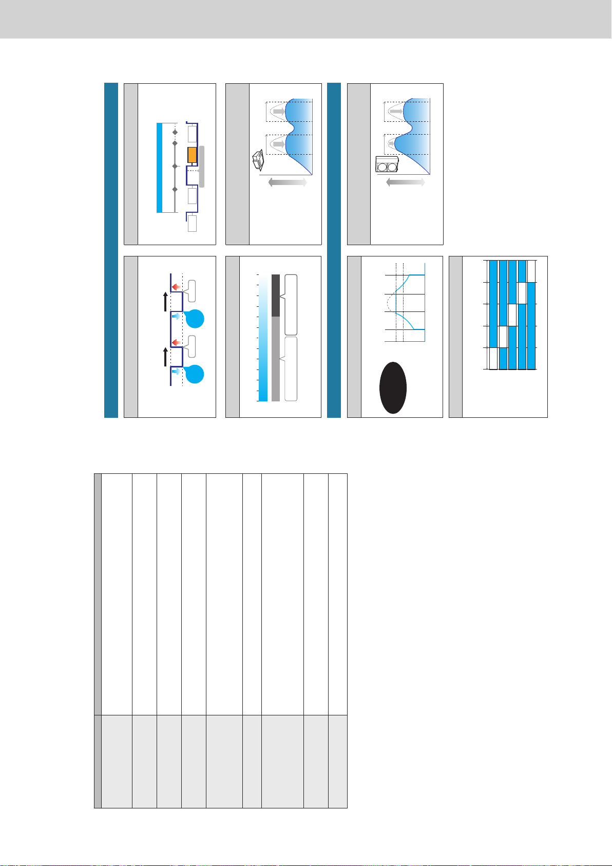
Operating Instructions Intelligent Controller
8
Explanation of terms
This section explains the terms used in this document.
Term Explanation
Adaptor address The address allocated to a single communication adaptor (sold separately). If the pulse meter is connected to a
communication adaptor, use the address of the adaptor.
Setting
No.0: This unit (setting complete)
No.1 to 7: Settings with the communication adaptor
Linked systems address This is a grouping of indoor units and/or outdoor units connected to the same inter-unit control wiring.
2 linked systems can be connected to this unit or a communication adaptor (sold separately).
Setting
No.1 and 2 (xed)
Outdoor unit systems address An outdoor unit and the grouping of indoor units connected by the coolant piping.
A single linked system can consist of a maximum of 30 outdoor unit systems.
Setting
No.1 to 30: Set on the outdoor unit for each linked system
Indoor unit address In an indoor unit system, this is a xed number allocated to an indoor unit.
This is also allocated to each indoor unit for group control.
Setting
No.1 to 64: Set on the indoor unit for each outdoor unit system
Central address This is a xed value within the linked system and is shared with other centralised controllers (system controllers,
etc.).
In group control, all indoor units belonging to a group have the same address.
In this document and on the unit, this is described as the “CNTR addr.”.
Setting
No.1 to 64: Set on this unit and other central controllers for each linked system
Unit name In group control, this will be the same name. This is the minimum unit used for operation, monitoring, and scheduling.
Setting
Set on this unit
Distribution group A distribution group consists of multiple (or single) areas and matches with the measuring range of a pulse meter,
with the distribution ratio of the grouping totalling to 100%. A maximum of 8 groups can be created across the whole
system.
With time distributing, it is not possible to mix PAC and GHP in a single distribution group.
You can have PAC and GHP in the same group if you are using load distributing.
Setting
No.1 to 8: Set on this unit
Area group An area group is one grouping used for calculating distributions (or for operating or monitoring) and consists of
multiple (or single) indoor units. A maximum of 256 groups can be created across the whole system.
Setting
No.1 to 256: Set on this unit
Control groups Control groups consist of multiple (or single) indoor units or outdoor units controlled the same in cyclic control
settings. A maximum of 10 groups can be set for indoor units and a maximum of 5 groups can be set for outdoor
units.
9
The Energy Saving function
This reduces waste in air conditioning so that you can save energy without replacing the air conditioning
units.
e-CUT function
The Demand function
Set temperature auto return
When you want to return to the set temperature after a certain
time even if the temperature is changed. (P.77)
30 minutes later
Change Change
30 minutes later
Return!
28 °C
22 °C
Return!
Demand settings
(indoor unit/outdoor unit)
When you want to suppress the maximum demand for electricity
or maximum gas consumption. (P.89, P.92)
Reduces CO
2
emissions, helps
prevent global warming!
8:00 12:00 20:00 Time16:00
Electricity or gas consumed
Demand 1
Demand 2
Set temperature range limit
When you want to limit the temperatures that can be set. (P.83)
30 °C28 °C26 °C24 °C22 °C20 °C
Reduced consumption of electricity
or gas by over cooling
Set temperature restricted to the
range between 26 °C and 30 °C
18 °C
High LowElectricity or gas consumed
Unattended auto shutoff
When you want to operate outside of a schedule but to monitor
and stop automatically. (P.80)
Time set for unattended auto shutoff
ON
OFF
Detect Detect Detect
60 min. 60 min.
Forget to turn off
60 min.
AUTO
OFF
AUTO
OFF
AUTO
ON
MANUAL
ON
9:0023:0022:0821:00
Demand/peak shaving settings/
Peak cut settings*
2
Specify time slots
when you want
operation capacity
of the outdoor
units reduced.
(P.94)
*1 The “Efcient operation setting” is the name of setting when using gas heat
pump air conditioners.
*2 The “Peak cut settings” is the name of setting when using gas heat pump air
conditioners.
Time
10:00 12:00 15:0013:00
High
Electricity or gas consumed
Low
Energy saving timer/Efcient operation
setting*
1
Specify time slots
when you want
operation capacity
reduced. (P.85)
10:00 12:00 15:00
Time
13:00
High
Electricity or gas consumed
Low
Indoor/outdoor unit cyclic
When you want operation capacity of the outdoor units reduced
during certain repeated intervals. (P.97, P.101)
5 min.
Forced stop
Forced stop
Forced stop
Forced stop
Forced stop
Control group 1
Control group 2
Control group 3
Control group 4
Control group 5
5 min.5 min. 5 min. 5 min.
Note
y Some models may not support these functions.
ー 50 ー
Page 53
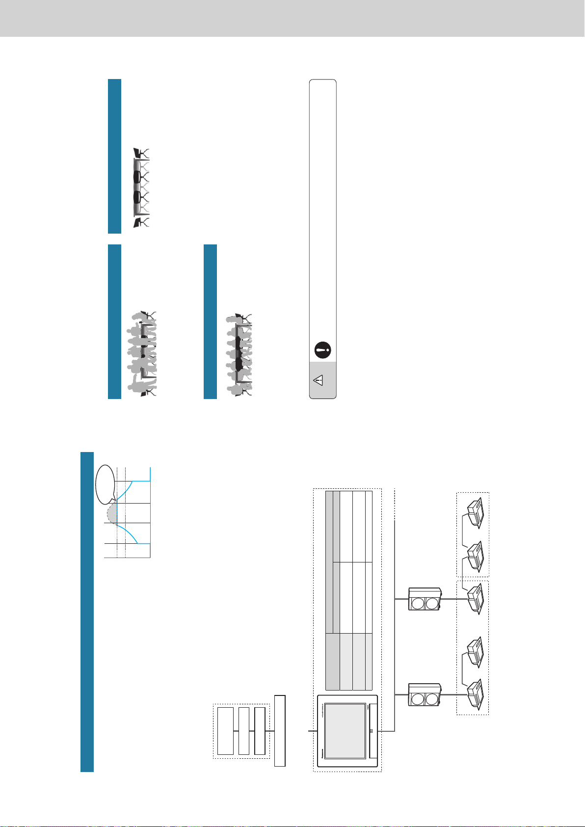
Operating Instructions Intelligent Controller
10
The Energy Saving function
Demand control
“Demand” indicates the “electricity demand” (average electricity over 30 minutes).
The basic charges for electricity are determined by the maximum value of
demand (the maximum electricity demand). This maximum demand for electricity
occurs during summer and winter when the air conditioning burden is the
greatest. One way of reducing electric power costs is to suppress the maximum
electricity demand during these periods. (Your actual situation depends on your
contract with your electricity provider)
Furthermore, by suppressing the maximum demand for electricity, you can assist
in the reduction of carbon dioxide emissions and help reduce global warming.
Demand control means that the air conditioning units are monitored so that their
electricity consumption does not exceed a contracted amount, and by setting a level as shown in the following diagram (demand 1, 2, or 3), the
performance of the air conditioning units can be controlled so that energy usage is reduced.
This unit suppress the maximum demand for electricity through automated control of air conditioning units by demand control output (demand
output) signals emitted by external equipments.
Demand control (with indoor unit demand settings)
Pulse signal generated
Intelligent Controller
Setting level
Setting example
Control group A Control group B
Demand 1 (contact A) Set temperature of the indoor unit
±1 °C
No setting
Demand 2 (contact B) Set temperature of the indoor unit
±2 °C
Set temperature of the indoor unit
±2 °C
Demand 3 (contact C) Indoor unit thermostat OFF Indoor unit thermostat OFF
Pulse meter
(electricity)
Pulse detector
Pulse converter
Control group A
Contact A (when cooling)
Set temperature of indoor unit rises 1 °C
Contact A (when cooling)
Set temperature of the indoor unit
remains unchanged
Control group B
External equipment
Load control output (demand output)
Contact A
Contact B
Contact C
Reduced electricity
consumption
Demand 1
Demand 2
8:00 12:00 20:00 Time16:00
Electricity consumed
11
Energy navigation function
Indoor units will run in energy saving modes according to the amount of human activity detected by
ECONAVI sensors (sold separately).
Warning
Do not use the ECONAVI feature in rooms where only disabled people or infants are present.
(It may cause damage to their condition or worsen their health)
If there is not much movement for a long time, the ECONAVI sensor may determine that the room is unoccupied and stop the air
conditioning unit.
Note
y You can turn on or off the ECONAVI feature on this unit.
y You will need a separate remote controller* with ECONAVI functionality in order to make advanced settings for the ECONAVI feature. Refer to
the operating instructions for the remote controller* with ECONAVI functionality for details on how to congure the feature.
y Even if the target temperature is changed by ECONAVI, the set temperature displayed on the unit will not change.
y Even if the mode is switched to fan due to the absence of people (standby mode), the mode displayed on the unit will not change.
y When running multiple indoor units, the energy reduction effect may be reduced depending on the conditions in the room.
* Multi-function wired remote controller (CZ-RTC5 or later)
When there is a lot of human activity
z In cooling or drying mode
Operates at the set temperature.
z In heating mode
The air conditioners run at a temperature lower than the set
temperature.
When there is not a lot of human activity
z In cooling or drying mode
The air conditioners run at a temperature higher than the set
temperature.
z In heating mode
Operates at the set temperature.
When there are no people
When there is a continuous 20 minute period of no people
z In cooling or drying mode
The temperature is set higher than when there are people in the
room.
z In heating mode
The temperature is set lower than when there are people in the
room.
When there are no people for about an hour
y The units run according to the mode set for when there are no
people. The factory preset is for low energy use operation to
continue with the temperature suppressed. (Refer to the operating
instructions for the ECONAVI sensor for information on the
operation mode when there are no people.)
y If people are detected while operating in the Absent mode, the air
conditioners return to a mode appropriate to the level of activity.
ー 51 ー
Page 54
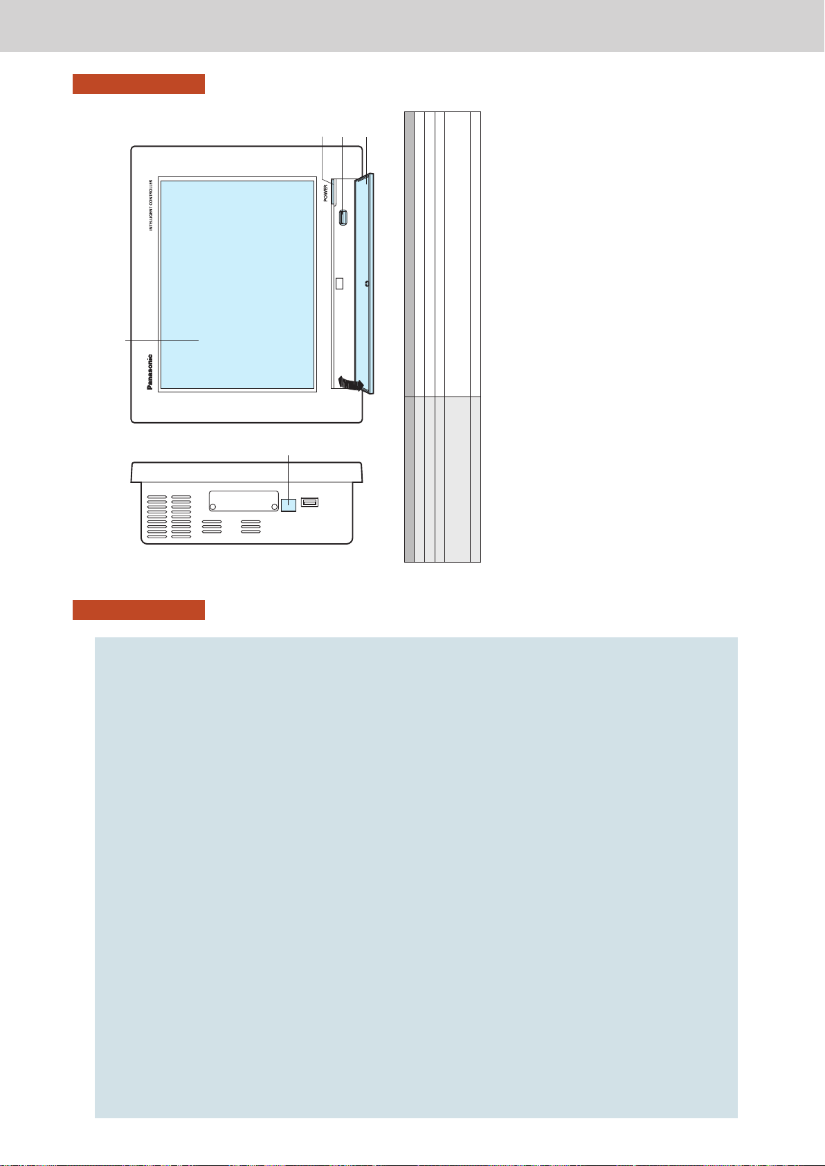
Operating Instructions Intelligent Controller
12
Preparations before changing settings
Preparation
Preparations before changing settings
This chapter describes the part names of the unit and their functions and also explains some basic operations.
13
Preparations before changing settings
Preparation
Part names
(1)
(2)
(3)
(4)
Name Explanation
(1) Colour LCD with touch panel You can operate the unit by touching the screen with your ngers.
(2) Power indicator This lights when the power is on.
(3) USB terminal Connect a USB memory device here to backup data from this unit (settings, accumulation/distribution).
(4) Storage door Open this cover to connect a USB memory device to the USB terminal.
To open, gently push on the storage door and then allow to drop down.
To close, lift the storage door and gently press closed.
(5) LAN terminal Connect to a network with wiring.
(The illustration shows the storage door open)
(Left side)
(5)
ー 52 ー
Page 55
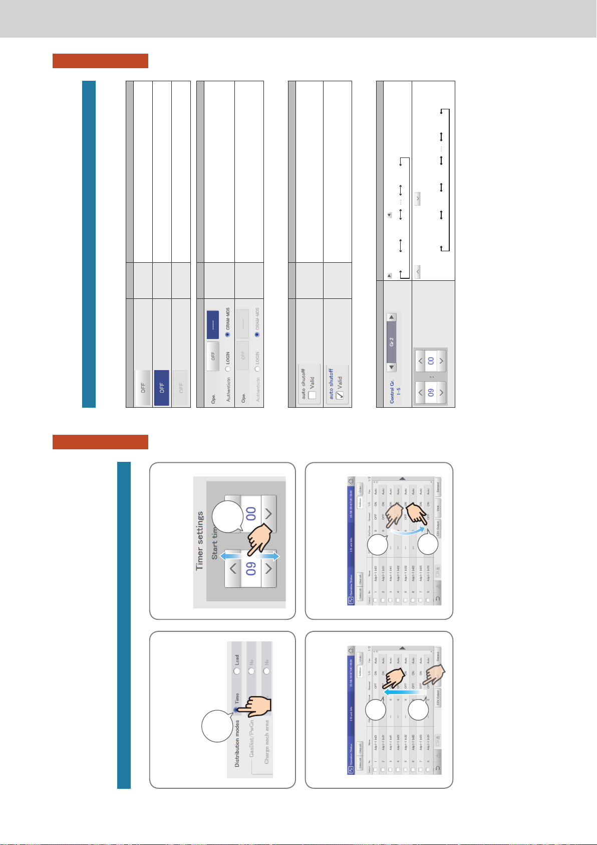
Operating Instructions Intelligent Controller
14
Preparations before changing settings
Preparation
Operations on this unit
Operations on this unit are performed by following menus.
The screens used for operations all follow a common pattern, with the screens being easy to read and easy
to use.
Touch
This is a light touch with a nger on the buttons or text
boxes displayed on the touch panel.
Swipe
This is an operation where the nger is slid in a direction
(up or down) on the touch panel.
This is used to scroll slowly.
Flick
This is an operation where the nger on the touch panel is
icked in a direction (up or down).
This is used to scroll quickly.
Picker
This is an up and down movement of the nger touching
the screen, used to pick settings in elements such as spin
boxes.
Basic operation of the touch panel
This section describes the basic operations on the touch panel.
Touch!
Picker!
Swipe!
(slide the
nger)
Flick!
Touch
Touch
15
Preparations before changing settings
Preparation
Operations on this unit
Buttons and boxes
There are varieties of buttons and boxes on the screen that you use to perform operations and settings on the touch panel.
Buttons
These are used to switch screens, save settings, switch settings on or off, select items, and similar operations.
Display example Status Explanation
Setting is off In this state the setting is off.
Setting is on In this state the setting is on.
Setting
unavailable
This indicates that the setting is currently unavailable due to other conditions.
Display example Status Explanation
Selected The highlighted item is the one that is currently selected.
Selection
disabled
This indicates that the selection is currently unavailable due to other conditions.
Check boxes
These are mainly used to switch on or off item selection and functions.
Display example Status Explanation
Unselected In this state the item is not selected.
Selected In this state the item is selected. (In this example, the automatic stop feature will operate.)
A check mark appears when you touch it. The check mark disappears when you touch it
again.
Spin boxes
These are used to switch the display of items and to set numeric items such as time.
Display example Explanation
takes you to the next item. takes you to the previous item.
Items may cycle around in the following way:
Gr.1 Gr.2 Gr.5
increases the numeric gure. decreases the numeric gure.
The numbers will change continuously if you continue to touch the button.
The numbers cycle around in the following way:
For example: When the number is an “hour”
“(blank)” “00” “01” “23”
ー 53 ー
Page 56
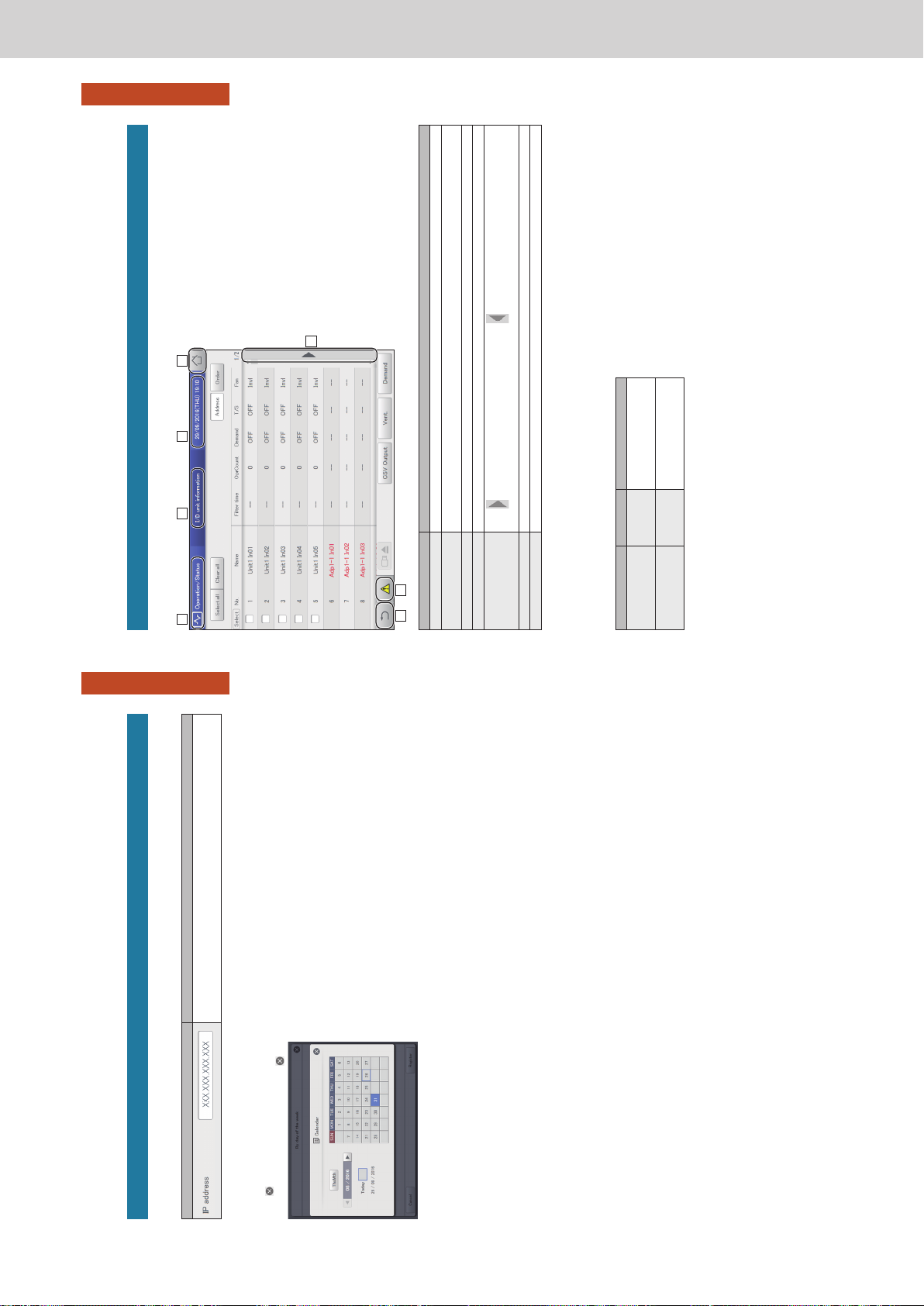
Operating Instructions Intelligent Controller
16
Preparations before changing settings
Preparation
Operations on this unit
Buttons and boxes (continued)
Text boxes
These are used when you need to edit some text.
Display example Explanation
The touchscreen keyboard appears when you touch the text box.
Use the touchscreen keyboard to enter the text.
Refer to “Number and letter input” (P.188) for instructions on how to enter text.
Dialogues
These are elements that appear on the screen and are mainly used for settings.
They close automatically once you have registered the settings.
Touch
to close the dialogue without changing the setting.
(There may also be cases where you touch
at the top right of the screen to register the setting)
17
Preparations before changing settings
Preparation
Operations on this unit
How to read the screens
There are some items and icons common to the operations and settings screens.
The follow explains the items and icons.
A B C D
F
E
G
Name Explanation
A Submenu name This displays the submenu name.
B Operations/Settings
screen name
This displays the operations/settings screen name.
C Date and time The current date and time is displayed.
D “Home” icon Touch this to display the Top menu (P.18).
E Scroll buttons
Touch
on the right side of the screen to scroll to the right. Touch to scroll to the left. (The display changes according to the
direction you can scroll.)
F “Back” icon Touch this to go back to the previous menu.
G “Warning” icon The “Alarm list” screen is displayed when you touch this. (→ “Checking on current alarms” (P.35))
z In this document and on the unit, indoor units are described as the “I/D”.
z In this document and on the unit, outdoor units are described as the “O/D”.
Notations in this document
Menu names, screen names, etc., are shown as follows in this document.
Type Notation Example
Top menus
Screen names
Screen display items
“xxx” “Oper./Status”
“I/D unit list” screen
“Select” column, “ON/OFF”
Submenu names
Screen menu names
Button names
[xxx] [Operation/Status]
[I/D unit list]
[Operation]
ー 54 ー
Page 57
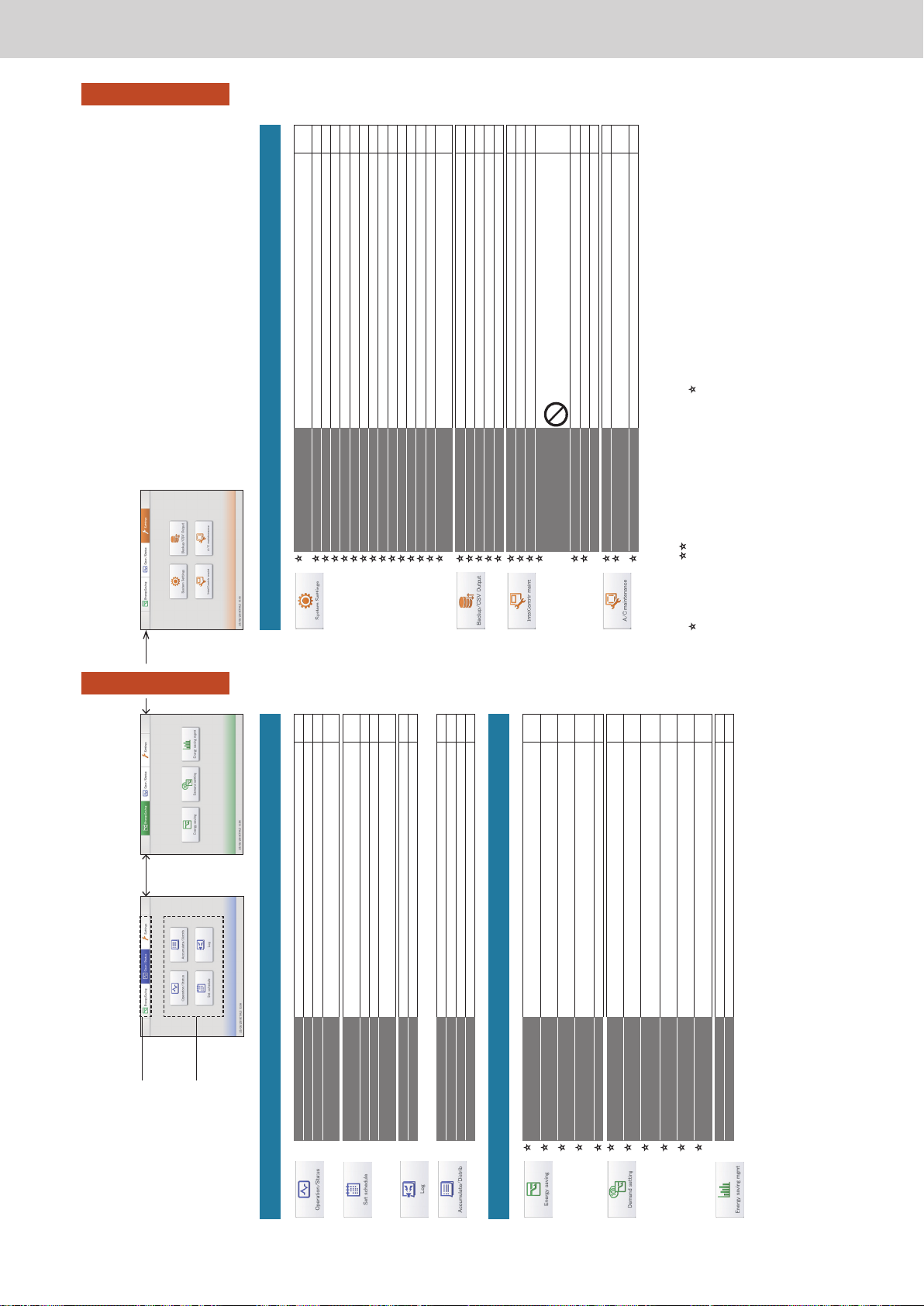
Operating Instructions Intelligent Controller
18
Preparations before changing settings
Preparation
Menu list
1
Select the top menu.
z Touch one of the “EnergySaving”,
“Oper./Status”, or “Settings” tabs.
2
Select the submenu.
Oper./Status EnergySaving
Oper./Status
(Check on the status of connected units)
Submenu Screen menu Overview Page
I/D unit list
Check the operational status of the indoor units in a list. 24
I/D unit information
Check the details about the indoor units (number of operation cycles, etc.) in a list. 28
O/D unit information
Check the details about the outdoor units (outdoor temperatures, etc.) in a list. 32
Alarm list
You can view a list of units with current alarms, where you can check the unit, the alarm
type, and the date of the alarm.
35
Schedule/results
You can see the schedules set up for the future and how they performed in the past in a
list.
53
Calendar
You can allocate a single day’s schedule to a calendar.
49
Schedule setting
You can register the schedule for a single day.
43
Update schedule
You can modify a schedule that you have registered (only from the day of the change up
to 4 days later, or a total of 5 days).
55
Alarm log
Check the log of alarms that have occurred in the system in a list. 58
Operation/Status change log
Check the log of operation/status changes of the indoor units in a list. 61
I/D unit acc.
Check the accumulated data for the indoor units in a list.
65
O/D unit acc.
Check the accumulated data for the outdoor units in a list.
67
Pulse acc.
Check the accumulated data for the pulse meters in a list.
69
Distribution data
Check the details about distribution calculations in a list. 72
EnergySaving
(Perform energy saving settings)
Submenu Screen menu Overview Page
Set temp. auto return
Even if the temperature initially set is changed, the temperature automatically returns to
the set one after a certain amount of time.
77
Unattended auto shutoff
If the indoor unit automatically stops at the set time but then is started again, this setting
automatically stops the unit again repeatedly at set intervals.
80
Set temperature range limit
Restrict the temperatures that can be set by setting upper and lower limits on
temperatures.
83
Energy saving timer/Efcient
operation setting*
You can specify time slots when you want operation capacity reduced.
85
Out unit silent setting
Set a time for the outdoor unit to operate at a lower level at night compared to the day.
87
I/D unit demand settings
You can automatically control indoor units to cut the maximum demand for electricity or
maximum gas consumption.
89
O/D unit demand settings
You can automatically control outdoor units to cut the maximum demand for electricity or
maximum gas consumption.
92
Demand/peak shaving settings/
Peak cut settings*
Limit the electricity or gas consumed by outdoor units during the set time slot.
94
O/D unit cyclic
At specied 10 minute intervals, the thermostats of outdoor units in control groups are
turned off and restored repeatedly in order.
101
I/D unit cyclic
At specied intervals (3, 4, or 5 minutes), the thermostats of indoor units in control
groups are turned off and restored repeatedly in order.
97
Register demand point
Register the contacts between the external equipments and the main unit (Contact A,
Contact B, Contact C).
104
Bar chart
Quantities of energy usage (electricity, gas), etc., are shown in bar charts.
109
Line graph
Temperature changes, etc., are shown in line graphs.
113
* When using gas heat pump air conditioners
19
Preparations before changing settings
Preparation
Menu list
Settings
Settings
(Perform other miscellaneous settings)
Submenu Screen menu Overview Page
Calendr sttngs for distr calc
Set specied days, cut-off days, particular time slots (regular hour ranges) and days of
the week for calculating distributions.
148
I/D unit settings
Change settings on indoor units, such as indoor unit addresses, groups belonged to, etc. 141
O/D unit settings
Change settings on outdoor units (addresses, etc.). 145
Schedule group name settings
Edit the name of the schedule group. 151
Area group name settings
Edit the name of the area group. 153
Distribution group settings
Edit the name of the distribution group. 155
Pulse meter settings
Make allocations between pulse meters and distribution groups. 158
Distribution mode settings
Set the mode used for distributing when calculating charges. 160
Distribution Ratio settings
Set the units for calculating electricity and gas usage charges. 161
Event control
Perform linked control by setting input and output conditions for devices. 162
Network settings
Make settings to enable remote control over a network. 123
Email settings
Congure the outgoing mail server. 168
Web user settings
Register users that will access the unit over a network. 125
Communication adapter setting
Register the communication adaptor connected to this unit. 170
Check conguration*
Modify the registered conguration when there have been changes to the conguration
of the system.
200
Backup
Save data (settings, accumulation/distribution, logs) to USB memory devices. 130
Restore
Restore data that has been stored in the unit or saved to a USB memory device. 132
CSV Output
Export (output) the settings for this unit in CSV format. 134
CSV Input
Import (input) the settings for this unit in CSV format. 136
Auto-save CSV le
Saves the CSV les (distributions, logs) automatically generated in this unit. 138
Display/Volume settings*
Adjust the brightness of the unit’s screen and the sound of the buzzer. 173
Intelligent Controller info
Register the contacts for servicing (telephone numbers) for this unit. 174
Software update*
Update the software for this unit. 175
Initialize*
Initialise the settings for this unit. 176
All data will be lost when you initialise.
Do not initialise under any circumstances.
Language&TimeZone sttngs
Set the language to be used when setting and operating this unit. 179
Date settings
Manually set the date and time. 178
Open license
The licences for the freeware is displayed. —
Test run
Perform a test operation of the indoor unit after installing this unit. 181
A/C communication settings
Make settings such as the communications protocol between this unit and the air
conditioning units.
184
Maintenance information
Register the units that will require maintenance. 186
* These settings are not available for setting or operation over the network.
Menus marked with require you to enter the admin number (password) when you select them.
menus require entry of the level 1 or higher admin number, while requires the level 2 admin number.
Refer to “Input of the admin number (password)” (P.22) for details.
ー 55 ー
Page 58
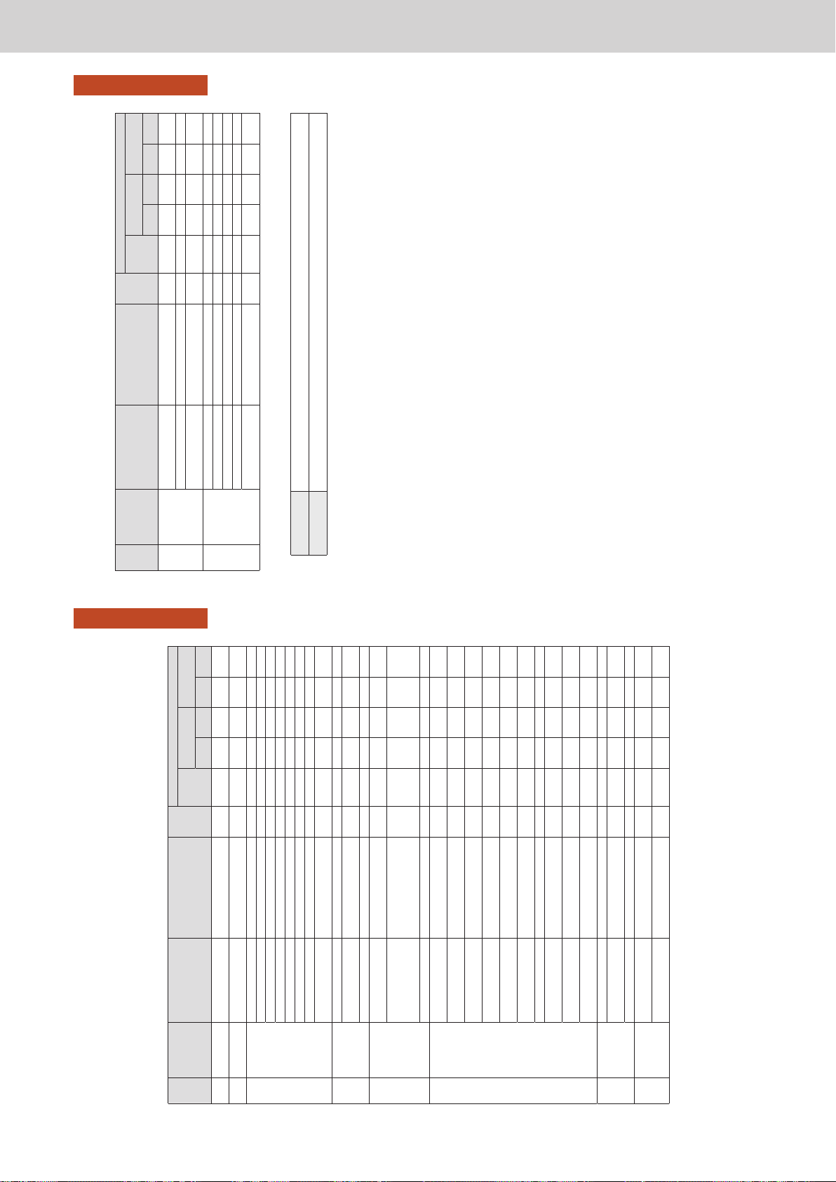
Operating Instructions Intelligent Controller
20
Preparations before changing settings
Preparation
Initial settings
The initial settings are those items that require setting after the unit is installed so that the system operates
normally.
The unit will operate normally if you make settings according to the following ow for the type of operation
intended.
: Settings required. : Settings may be required. : Settings not required.
Step Category step Setting Screen menu names
Reference
page
Operation
Air
conditioning
operations
only
Distribution rate
display only
Quantity used,
charges display
Time Load Time Load
1 Date settings
Setting the current date
and time
Date settings
178
2
Composition
loading
Conrming the connection
conguration
Check conguration
—
3 Unit related
Central address*
1
I/D unit settings 141
Name of the indoor units I/D unit settings 141
Distribution group I/D unit settings 141
Area group I/D unit settings
141
*
2
Control group I/D unit settings
141
Not batch, not managed I/D unit settings
141
Name of the outdoor units O/D unit settings
145
Local remote controller
prohibition setting
A/C communication settings
184
4 Group related
Name of the area group Area group name settings
153
*
2
Name of the distribution
group
Distribution group settings
155
Name of the schedule group Schedule group name settings
151
5
Pulse meter
related
Association with the
distribution group
Pulse meter settings
158
Type of pulse meter
(electricity/gas), multiplying
factor (number of pulse
units)
Pulse meter settings
158
Name of the pulse meter Pulse meter settings
158
6
Distribution
related
Distribution modes (time/
load)
Distribution mode settings
160
Power distribution
calculation target*
3
Distribution mode settings
160
Energy saving distribution
setting
Distribution mode settings
160
*
4
*
4
Distribution of gas for power
generation
Distribution mode settings
160
*
5
*
5
Setting the monthly cut-off
days
Calendr sttngs for distr calc
148
*
6
Setting the regular hour
range
Calendr sttngs for distr calc
148
Setting specied days Calendr sttngs for distr calc
148
Currency for electricity or
gas charges*
7
Distribution Ratio settings
161
Setting the capacity of the
indoor units*
8
I/D unit settings
141
Setting the capacity of the
electric heater*
9
I/D unit settings
141
7
Scheduling
related
Schedule for a single day Schedule setting
43
Allocating a schedule to a
calendar
Calendar
49
Schedule group I/D unit settings
141
8 Event control
Input point (names and
conditions)*
10
Event control
162
Output point (names and
operation)*
11
Event control
162
21
Preparations before changing settings
Preparation
Initial settings
Step Category step Setting Screen menu names
Reference
page
Operation
Air
conditioning
operations
only
Distribution rate
display only
Quantity used,
charges display
Time Load Time Load
9 Network related*
12
IP address, net mask,
DHCP, etc.
Network settings
123
Setting to send alarm mails Email settings
168
User ID, password,
privileges
Web user settings
125
10
Intelligent
controller related
Buzzer volume Display/Volume settings
173
Brightness of the back light Display/Volume settings
173
Auto logout time Display/Volume settings
173
Identication number Initialize
176
Initialise the days
accumulated data*
13
Initialize
176
*1 Attention needs to be paid to administration divisions when devices such as systems controllers are to be used in conjunction with this unit.
*2 Settings required when area administration is to be performed.
*3 Select the object of calculations for electricity distributing from the following:
Operating hours Select when consideration is to be paid to the electricity for the indoor units. The electricity for outdoor units and indoor units are both
loaded into this unit and distributed.
Thermostat on times Select when no consideration is to be paid to the electricity for the indoor units. The electricity for outdoor units only is loaded into this
unit and distributed.
*4 If the air conditioning units included in the system are multi-function types supporting simultaneous heating and cooling or ice thermal storage models, settings
are required.
*5 Settings are required only when units are GHP with generators.
*6 Settings are required when only the accumulation operating time is to be managed.
*7 This must be set if you want to display charges.
*8 This only needs to be set for interface adaptors. (→“Interface adaptors (sold separately)” (P.198))
*9 This is used when calculating load distributing.
*10 Set items such as batch startup and stopping from external input.
*11 Set items such as batch alarm output to external devices.
*12 Required when logging in through a network device to operate and monitor.
*13 Clears the data calculated from test operation of the air conditioning units before hand over.
ー 56 ー
Page 59
Operating Instructions Intelligent Controller
22
Preparations before changing settings
Preparation
Input of the admin number (password)
When using this unit
Items marked with or in the “Menu list” (P.18 and P.19) require you to enter an admin number before use to maintain security.
1. The admin number input screen is displayed when you touch a menu on the screen.
2. Enter the admin number.
y Depending on the level of admin number you have, you may not be able to enter the menu.
When using a browser
Depending on your user level, some menus may not be displayed.
Refer to “Control remotely” (P.128) for information on how to access the menus.
You may need to enter the admin number again after gaining access, depending on the menu.
See “When using this unit” above for information on how to enter the admin number.
23
Check the status of air conditioning units
Operation/Status
Check the status of air conditioning units
This chapter explains how to check the setting status of air conditioning units (indoor units and outdoor units).
This unit allows you to conrm and change settings for indoor units, and conrm the operational status of indoor
units and outdoor units.
You can also check alarms that have occurred in the system in a list.
Screen menu Overview Page
I/D unit list
Check the operational status of the indoor units in a list. 24
I/D unit information
Check the details about the indoor units (number of operation cycles, etc.) in a list. 28
O/D unit information
Check the details about the outdoor units (outdoor temperatures, etc.) in a list. 32
Alarm list
You can view a list of units with current alarms, where you can check the unit, the alarm
type, and the date of the alarm.
35
ー 57 ー
Page 60
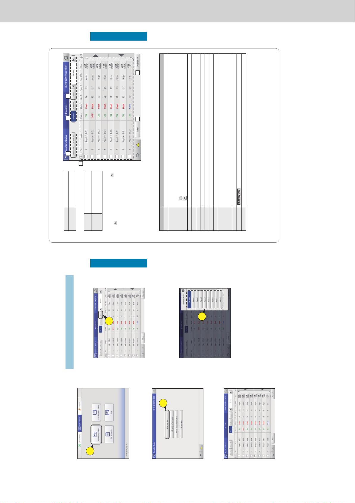
Operating Instructions Intelligent Controller
24
Check the status of air conditioning units
Operation/Status
Checking the settings on the indoor unit
You can check the setting status of all indoor units connected to this unit in a list. You can also change the
display to show by area.
1
Touch [Operation/Status] in “Oper./
Status”.
1
2
Touch [I/D unit list].
z The “I/D unit list” screen is displayed.
2
3
Checking the status of settings. (P.25)
Note
y You can select indoor units to change their settings. (→ “Changing
the settings on the indoor unit” (P.26))
Select the area to display
1
Touch [Area].
z The “Select Area” dialogue is displayed.
1
2
Select the area to display.
z If 9 or more area groups have been registered (P.153), you
can scroll up or down by swiping or icking the screen.
z The “Select Area” dialogue is closed and the settings of the
selected area are displayed in the list.
2
25
Check the status of air conditioning units
Operation/Status
“I/D unit list” screen
A: [Select all]/[Clear all] buttons
[Select all] Select all indoor units.
[Clear all] Cancel selection of all
indoor units.
B: Change list order.
Display The display follows the order set
in “I/D unit settings” (P.141).
Address The display follows the address
order set in “I/D unit settings”
(P.141).
C: Select the area to display in the list.
The area changes each time you touch
and
. Touch [Area] to display the “Select
Area” dialogue. (→ “Select the area to
display” (P.24))
(“All area” → “Area1” → “Area2” →…→
“AreaXXX*” → “All area”)
* “XXX” stands for the number of the last of
the registered areas.
D: The settings of the indoor units are displayed
in a list.
You can scroll up or down by swiping or icking the screen.
y Each time you touch the item name, the order switches between ascending (▲) and descending (▼).
y Some items are not displayed for some models.
Item Explanation
[Select] Select the indoor units you want to operate.
Name The names of the indoor units are displayed.
When an icon is displayed to the right of the name, this indicates that some situation has occurred.
(Alarm displays)
: The indoor unit lters need cleaning
: An alarm has occurred
Status This indicates the current operating status (ON/OFF). (P.26)
Mode The current operating mode (Heat, Dry, Cool, Fan, Auto) is displayed. (P.26)
Set T. The current temperature setting is displayed. (P.27)
Room T. The current room temperature is displayed.
Fan SPD The current fan speed (High, Mid., Low, Auto) is displayed. (P.27)
Flap The airow direction is displayed. (P.27)
Prhbt. This indicates the remote controller operation “Accept” or “Prhbt1” to “Prhbt4”. (P.27)
Sche. This indicates the setting status of the schedule (Yes, --, OFF).
Yes: This indicates that a schedule is set.
--: This indicates that a schedule is not set.
OFF: This indicates that a schedule is set, but that the schedule has not started because indoor units are off or similar.
Eco “” is displayed when the energy saving setting is running. (P.27)
ECONAVI
“
” is displayed when the ECONAVI setting is running. (Only for models with ECONAVI) (P.27)
e-CUT “” is displayed when the e-CUT function is running.
E: After cleaning the lters, touch to clear the lter icon from the display.
F: The “Settings” dialogue of the indoor unit selected at D is displayed.
You can change the settings for the selected indoor unit in the “Settings” dialogue. (→ “Changing the settings on the indoor unit”
(P.26))
y There may be differences in the items you can set depending on the model of the indoor unit.
y When you have selected multiple units, setting items in common are displayed in the “Settings” dialogue.
A B C
E
D
F
Checking the settings on the indoor unit
ー 58 ー
Page 61
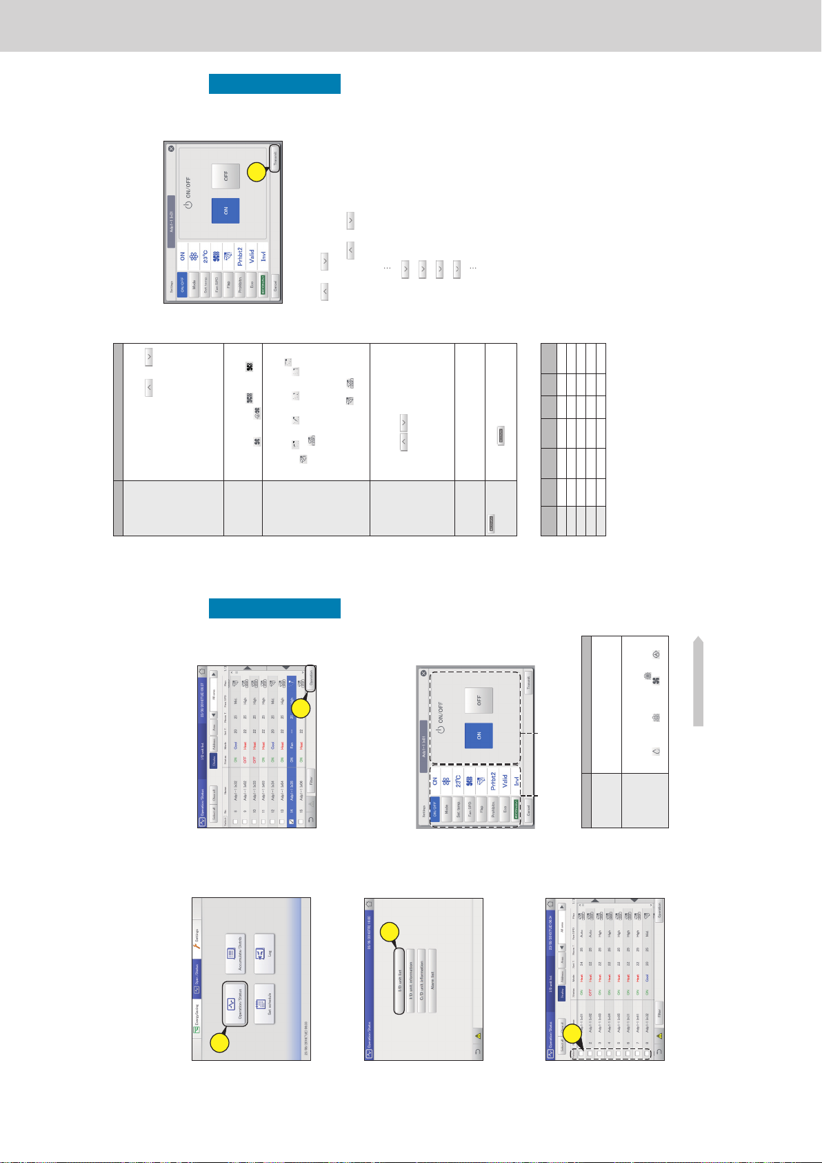
Operating Instructions Intelligent Controller
26
Check the status of air conditioning units
Operation/Status
Changing the settings on the indoor unit
You can select indoor units to change settings, for example, start or stop them, or change their set
temperature, etc.. Change settings in the “Settings” dialogue.
You can also select multiple indoor units and operate them using the same settings.
4
Touch [Operation].
z The “Settings” dialogue is displayed.
4
Note
y There may be differences in the items you can set in the
“Settings” dialogue, depending on the model of the indoor
unit.
y When you have selected multiple units, setting items in
common are displayed in the “Settings” dialogue.
5
Change the settings of the items.
Common display area Operation display area
Select an item from the common display area and set the
operation in the operation display area.
Item Explanation
ON/OFF Set whether to start or stop operation.
1) Touch [ON/OFF].
2) Select “ON” or “OFF”.
Mode Set the operating mode.
1) Touch [Mode].
2)
Select the operating mode (
(heating),
(drying), (cooling), (fan),
(automatic)).
Continued on next page
1
Touch [Operation/Status] in “Oper./
Status”.
1
2
Touch [I/D unit list].
z The “I/D unit list” screen is displayed.
2
3
Put a check mark in the “Select” column.
z Select the indoor units whose settings you want to change.
z You can touch [Select all] to change the settings in a batch.
3
27
Check the status of air conditioning units
Operation/Status
Item Explanation
Set temp. Set the temperature.
1) Touch [Set temp.].
2)
Set the temperature with and .
(± in 1 °C steps)
<Setting ranges>
y In cooling or drying mode: Between
18 °C and 30 °C
y In heating mode: Between 16 °C and
30 °C*
1
y Automatic: Between 17 °C and 27 °C
*1 The upper limit for gas heat pump air
conditioners is 26 °C.
Fan SPD Set the strength of the fan.
1) Touch [Fan SPD].
2)
Select the fan speed (
(high),
(mid),
(low), (automatic)).
Flap Set the direction of the airow.
1) Touch [Flap].
2)
Set the ap to the desired position (
(F1),
(F2), (F3), (F4), (F5),
(Swing)).
Touch
during the swing to stop the ap
at the desired position.
y Heating, fan, and automatic (heating)
can be adjusted in 5 steps and cooling
and dry can be adjusted in 3 steps.
y You can set either
or if the
model does not support airow direction
settings.
Prohibitn.*
2
Set whether to allow or prohibit use of the local
remote controller.
1) Touch [Prohibitn.].
2)
Use
to select from “Accept”,
“Prhbt1”, “Prhbt2”, “Prhbt3”, or “Prhbt4”.
Accept: Allows operations with the remote
controller.
Prhbt1 to Prhbt4: Operations on the
remote controller are restricted. You can
change the restricted operations. (→P.185)
Eco Enable or disable energy saving operation.
1) Touch [Eco].
2) Select “Valid” or “Invl”.
Enable or disable ECONAVI setting.
1)
Touch
.
2) Select “Valid” or “Invl”.
*2 Example of prohibiting or enabling remote controller use (factory
setting)
ON/OFF Mode Set temp.
Fan
SPD
Flap Eco
Accept
Prhbt1
Prhbt2
Prhbt3
Prhbt4
: Operation and setting with the remote controller is possible
: Operation and setting with the remote controller is not possible
6
Touch [Transmit].
z The settings are registered and the “Settings” dialogue
closes.
z To cancel the settings, touch [Cancel].
6
Note
y Touch (or ) at the upper value (or lower value) of the
set temperature and the set value becomes a blank (no setting).
Make the setting blank when you want no setting.
Furthermore, touch
(or ) and the upper value (or lower
value) is displayed.
For example: If upper value 30 °C and lower value 18 °C (when
cooling)
19 °C
18 °C (lower limit value) (blank) 30 °C (upper limit value) 29 °C
Changing the settings on the indoor unit
ー 59 ー
Page 62
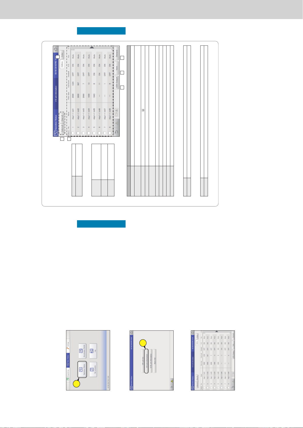
Operating Instructions Intelligent Controller
28
Check the status of air conditioning units
Operation/Status
Checking the operational status of indoor units
Check the operational status of indoor units (remaining lter time, number of operation cycles, etc.) in a
list.
You can also change the ventilation system and demand control settings (ON or OFF only).
1
Touch [Operation/Status] in “Oper./
Status”.
1
2
Touch [I/D unit information].
z The “I/D unit information” screen is displayed.
2
3
Check the setting details. (P.29)
Note
y You can select indoor units to change their ventilation output
settings. (→ “Changing the settings for ventilation output” (P.30))
y You can select indoor units to change their demand control
settings. (→ “Changing the demand control settings” (P.31))
29
Check the status of air conditioning units
Operation/Status
“I/D unit information” screen
A: [Select all]/[Clear all] buttons
[Select all] Select all indoor units.
[Clear all] Cancel selection of all indoor
units.
B: Change list order. The list order changes each
time you touch it.
Address The display follows the address
order set in “I/D unit settings”
(P.141).
Display The display follows the order set
in “I/D unit settings” (P.141).
O/D unit The display follows the address
order of the outdoor unit systems.
C: Indoor unit details are displayed in a list.
You can scroll up or down by swiping or icking
the screen.
Item Explanation
[Select] Select the units you want to make ventilation settings or demand settings for.
Name The names of the indoor units are displayed.
You can change the names. (→ “I/D unit settings” (P.141))
Filter time
This displays the approximate time remaining before
is displayed.
OprCount The number of operation cycles for the day is displayed.
Demand Demand control setting status is displayed. “ON” is displayed when demand control is set. (→ “Demand settings on
the indoor unit” (P.89))
T/S This displays the operational status of the thermostat. “ON” is displayed when the thermostat is working.
Fan The fan strength (High/Mid./Low/Brze/OFF) is displayed.
SuctnTmp The current inlet temperature is displayed.
DschgTmp The current outlet temperature is displayed.
VentOpen The ventilation output setting (ON or OFF) is displayed.
D: Change the settings for ventilation output.
The “Vent.” dialogue is displayed when you touch this. (→ “Changing the settings for ventilation output” (P.30))
ON Operation of the ventilation output starts.
OFF Operation of the ventilation output stops.
E: Change the demand control settings.
The “Demand setting” dialogue is displayed when you touch this. (→ “Changing the demand control settings” (P.31))
ON Demand control is set.
Cancel Demand control is cancelled.
F: The contents currently displayed are output to the USB memory device as a CSV le.
A
B
C
DF E
Checking the operational status of indoor units
ー 60 ー
Page 63
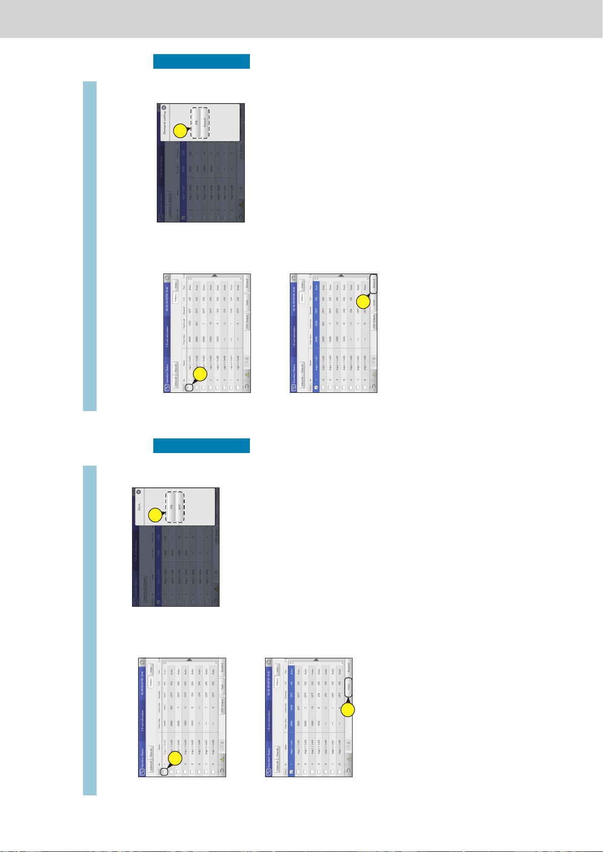
Operating Instructions Intelligent Controller
30
Check the status of air conditioning units
Operation/Status
3
Change the settings.
z The settings are registered and the “Vent.” dialogue closes.
3
1
Put a check mark in the “Select” column.
z Select the indoor units whose settings you want to change.
z You can select multiple indoor units.
1
2
Touch [Vent.].
z The “Vent.” dialogue is displayed.
2
Changing the settings for ventilation output
Checking the operational status of indoor units
31
Check the status of air conditioning units
Operation/Status
3
Change the settings.
z A conrmation message appears.
3
Note
y This setting is linked with “I/D unit demand settings”. (→
“Demand settings on the indoor unit” (P.89))
4
Touch [Yes].
z The setting is registered.
1
Put a check mark in the “Select” column.
z Select the indoor units whose settings you want to change.
z You can select multiple indoor units.
1
2
Touch [Demand].
z The “Demand setting” dialogue is displayed.
2
Checking the operational status of indoor units
Changing the demand control settings
Switch between setting and cancelling demand control. Refer to “Demand settings on the indoor unit” (P.89) for information about demand
control.
ー 61 ー
Page 64
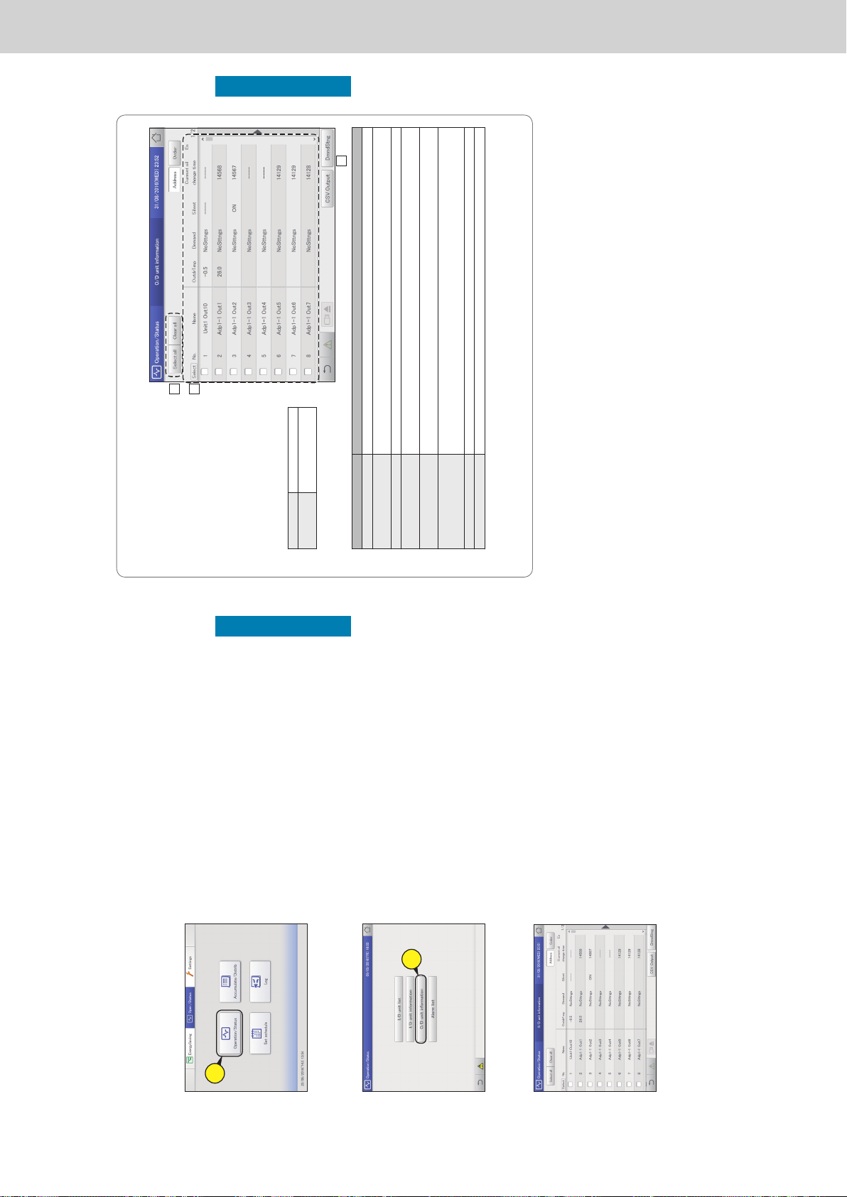
Operating Instructions Intelligent Controller
32
Check the status of air conditioning units
Operation/Status
1
Touch [Operation/Status] in “Oper./
Status”.
1
2
Touch [O/D unit information].
z The “O/D unit information” screen is displayed.
2
3
Check the setting details. (P.33)
Note
y You can select outdoor units to change their demand
control settings. (→ “Changing the demand control
settings” (P.34))
Check the details about the outdoor units (outdoor temperatures, demand setting status, etc.) in a list.
You can also select outdoor units to change their demand control settings (ON or OFF only).
Checking the operational status of the outdoor unit
33
Check the status of air conditioning units
Operation/Status
“O/D unit information” screen
A: [Select all]/[Clear all] buttons
[Select all] Select all outdoor units.
[Clear all] Cancel selection of all
outdoor units.
B: Outdoor unit details are displayed in a list.
You can scroll up or down by swiping or
icking the screen.
Item Explanation
[Select] Select the units you want to set demand control for.
Name The names of the outdoor units are displayed.
You can change the names. (→ “Basic settings on the outdoor unit” (P.145))
OutdrTmp The temperature outside is displayed.
Demand Demand control setting status is displayed.
(→ “Demand settings on the outdoor unit” (P.92))
Current oil change time The number of operating hours after the last oil change is displayed.
(Available only when using a gas heat pump)
Engine oil check sign This displays the check sign for engine oil.
(Available only when using a gas heat pump)
y If this sign is displayed, contact the place of purchase or your servicing agent to have the oil replaced.
Inverter instant.(kW) This displays the current value for the inverter generator instantaneous value of the ECO G HIGH POWER.
Solar instant.(kW) This displays the current value for the solar generator instantaneous value of the ECO G HIGH POWER.
C: Change silent mode.
The “Demand” dialogue is displayed when you touch this.
(→ “Changing the demand control settings” (P.34))
A
B
C
Checking the operational status of the outdoor unit
ー 62 ー
Page 65
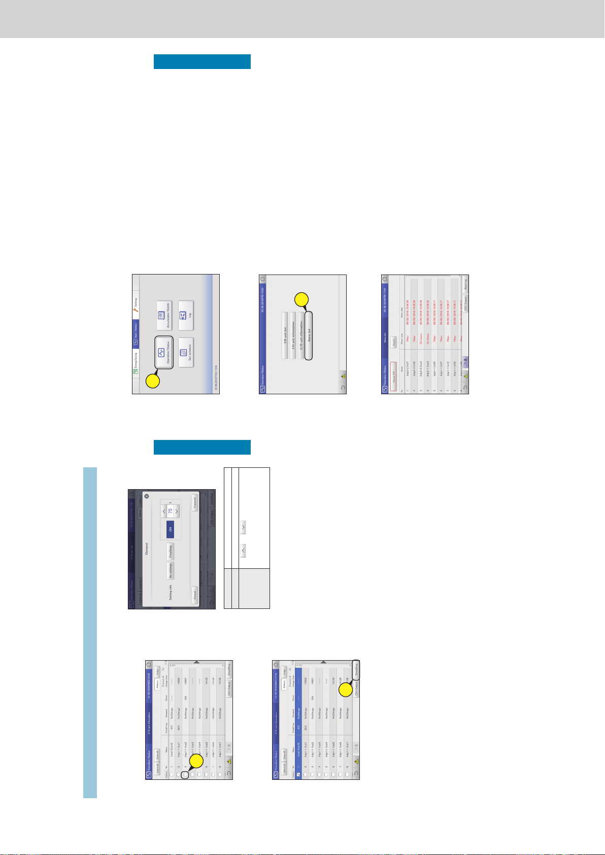
Operating Instructions Intelligent Controller
34
Check the status of air conditioning units
Operation/Status
3
Set the demand operating range.
[No settings] The demand operation setting is cancelled.
[FrceStop] Demand operation is forcibly stopped.
[ON XX%]
(Demand values)
Use
and to select an available
demand value for the selected outdoor unit.
y If multiple outdoor units are selected, the
demand values common between them are
displayed.
4
Touch [Transmit].
z The settings are changed and the “Demand” dialogue is
closed.
z To cancel the settings, touch [Cancel].
1
Put a check mark in the “Select” column.
z Select the outdoor units whose settings you want to
change.
z You can select multiple outdoor units.
1
2
Touch [DmndStng].
z The “Demand” dialogue is displayed.
2
Checking the operational status of the outdoor unit
Changing the demand control settings
35
Check the status of air conditioning units
Operation/Status
Checking on current alarms
You can check the indoor unit names, alarm codes, and dates and times of occurrence and recovery for
alarms that have occurred in the air conditioning system in a list. You can also do things such as output
the alarm list in CSV format and check the alarm log.
1
Touch [Operation/Status] in “Oper./
Status”.
1
2
Touch [Alarm list].
z The “Alarm list” screen is displayed.
2
3
Checking on current alarms. (P.36)
ー 63 ー
Page 66
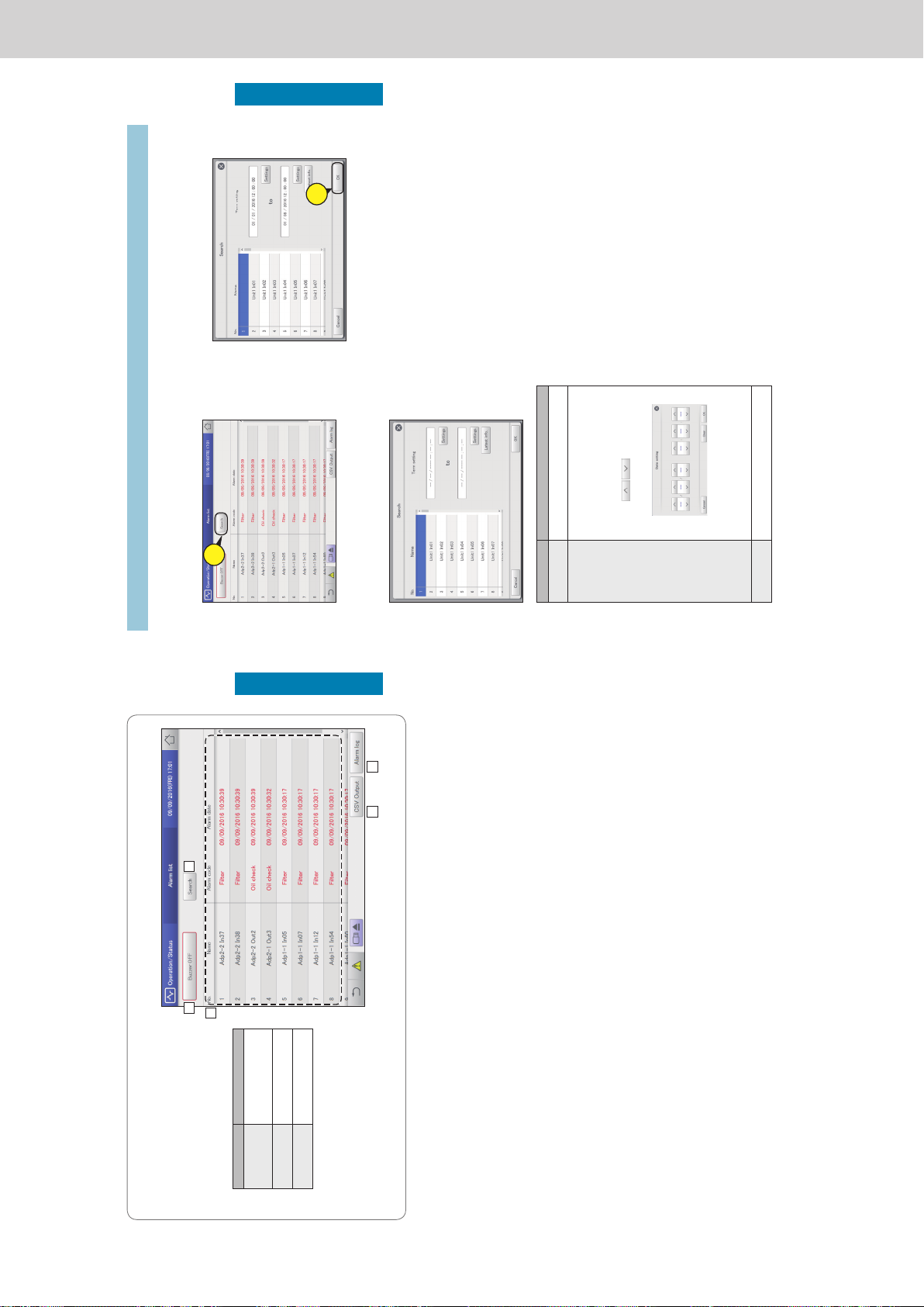
Operating Instructions Intelligent Controller
36
Check the status of air conditioning units
Operation/Status
“Alarm list” screen
A: Stop the alarm notication buzzer.
B: Set conditions (unit names, periods) to
search alarms.
(→ “Searching alarms” (P.37))
C: Display a list of current alarms.
You can scroll up or down by swiping or
icking the screen.
Item Explanation
Name The names of units where
alarms are currently
occurring are displayed.
Alarm code The alarm detail of current
alarms is displayed.
Alarm date This displays the date and
time the alarm occurred.
D: You can output (save) the displayed list of
alarms in CSV format.
(→ “Outputting (saving) the list of alarms in
CSV format” (P.38))
E: The “Alarm log” screen is displayed when
you touch this. (→ “Checking the alarm logs”
(P.58))
A B
ED
C
Checking on current alarms
37
Check the status of air conditioning units
Operation/Status
1
Touch [Search].
z The “Search” screen is displayed.
1
2
Setting the conditions.
Item Explanation
Name Select the name of the unit for which you want
to nd the information from the list.
Term setting Set the start and nish for the period you want
to search. The time at the top is the start of the
period and the time at the bottom is the end.
1. Touch [Settings].
y The “Date setting” dialogue is displayed.
2. Set the date and time.
y Use
to set the “Day”,
“Month”, “Year”, “Hours”, “Minutes”, and
“Seconds”.
3. Touch [OK].
y The settings are registered and the “Date
setting” dialogue closes.
y To cancel the settings, touch [Cancel].
[Latest info.] Touch to clear the period you have set and show
the most recent 100 alarms.
3
Touch [OK].
z Alarms matching the conditions are displayed in a list.
z To cancel the search, touch [Cancel].
3
Checking on current alarms
Searching alarms
ー 64 ー
Page 67
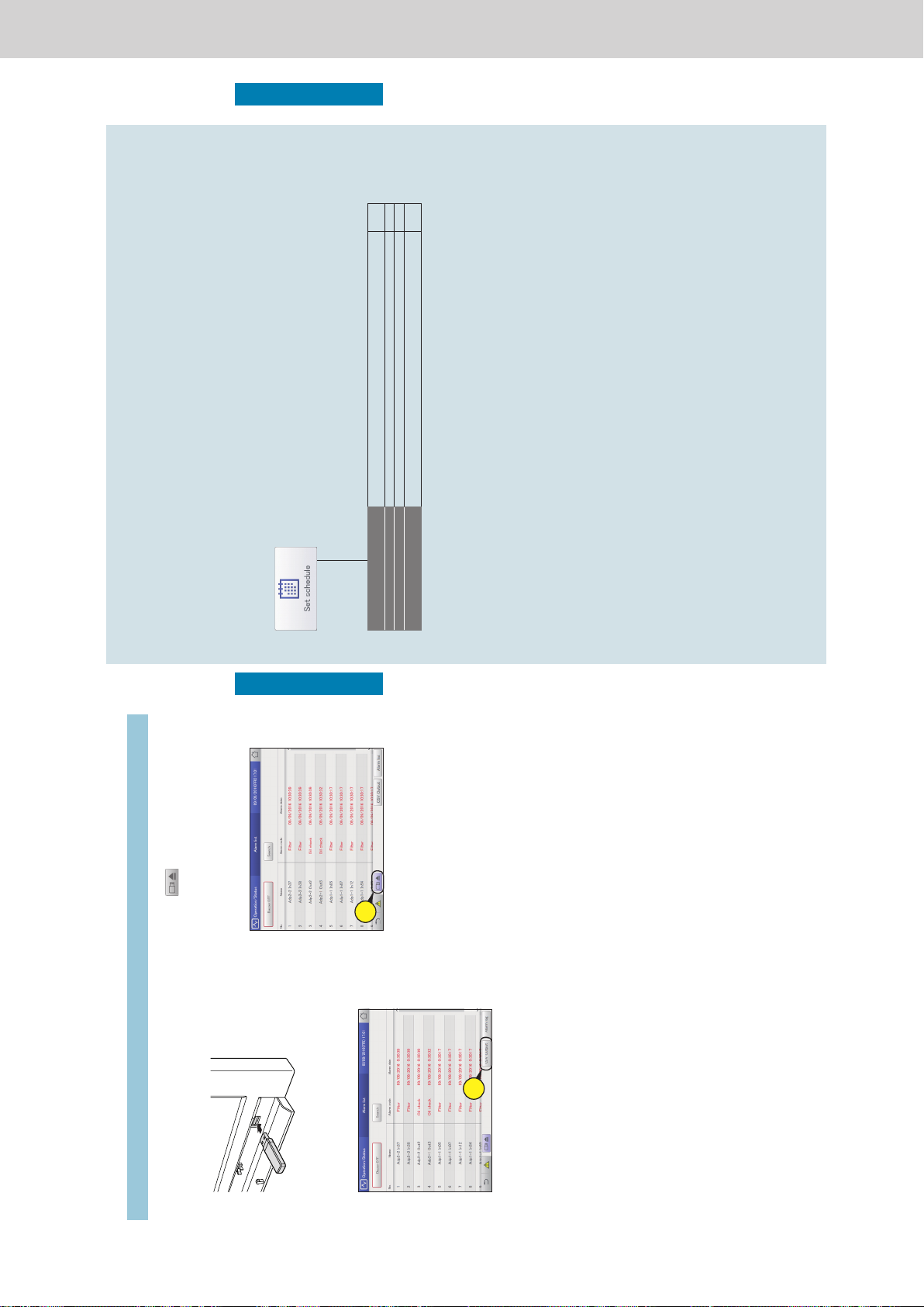
Operating Instructions Intelligent Controller
38
Check the status of air conditioning units
Operation/Status
1
Open the storage door and connect
a USB memory device to the USB
terminal.
2
Touch [CSV Output].
z A conrmation screen is displayed.
2
3
Touch [OK].
z The list of alarms currently displayed is output (saved) to
the USB memory device as a CSV le.
z When saving is complete, a message conrming that
saving is complete is displayed.
z The CSV le is saved to the “icxi/csv/almlist” folder.
(Example le name for the output le)
al_18052016.csv
4
Touch when you want to
disconnect the USB memory device.
z The message “USB memory can now be safely removed”
is displayed. Touch [OK] and then remove the USB
memory device.
z Close the storage door after removing the USB memory
device.
4
Checking on current alarms
Outputting (saving) the list of alarms in CSV format
39
Setting a schedule
Operation/Status
Setting a schedule
This chapter explains how to set schedules.
You can register a single day’s schedule as a pattern and then allocate to a date on the calendar.
Indoor units can be registered in groups or individually.
Screen menu Overview Page
Schedule/results
You can see the schedules set up for the future and how they performed in the past in a
list.
53
Calendar
You can allocate a single day’s schedule to a calendar. 49
Schedule setting
You can register the schedule for a single day. 43
Update schedule
You can modify a schedule that you have registered (only from the day of the change up
to 4 days later, or a total of 5 days).
55
ー 65 ー
Page 68
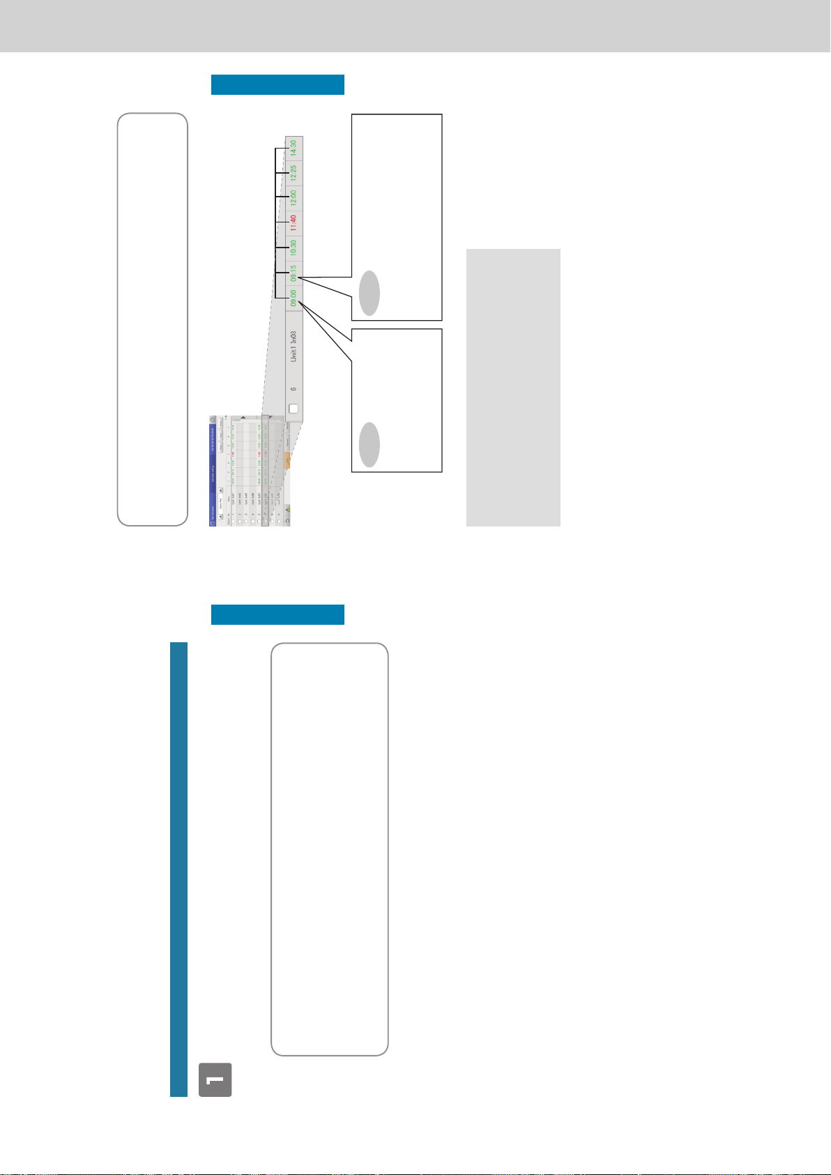
Operating Instructions Intelligent Controller
40
Setting a schedule
Operation/Status
Schedule setting ow
This system allows you to set schedules for each indoor unit so that they run automatically.
You can set schedules by month for up to 2 years in the future.
Furthermore, you can put indoor units that will run on the same schedule into “Schedule group”.
Schedules are set according to the following ow.
Setting a schedule
z “Setting a schedule” (P.43)
Register the schedule for indoor units.
y Decide a “daily running mode” to set when registering the schedule. You can register up to 50 types of daily running mode.
What is the “daily running mode”?
Scheduling patterns for indoor units (individually or as part of a schedule group) are called “daily running mode”.
Daily operating modes are registered as different patterns for schedules to match different days of the week, holidays, and
seasons.
Example of daily running mode settings
y Daily running mode for a working day (Monday to Friday) (“Mode1”)
y Daily running mode for Saturday (“Mode2”)
y Daily running mode for Sunday (“Mode3”)
* Schedule group: Indoor units that run on the same schedule registered in groups. To register into schedule groups, see
“Basic settings on the indoor unit” (P.141).
41
Setting a schedule
Operation/Status
What is a “setting cell”?
To set a schedule, you need to register operations in “setting cells”. The “setting cell” is the smallest unit of operations used to
congure a schedule.
You set “Time”, “ON/OFF”, “OpertnMode”, “Temperatre”, “Fan SPD”, “Flap”, “Prhbt”, and “EnerSavStg” in a “setting cell”. Each
time you change an operation (for example from “ON” to “OFF”), you register a different “setting cell”.
A schedule consists of a collection of these “setting cells” lined up.
The following is an example schedule set for an indoor unit.
Setting cell (this example shows “Time” displayed)
1 block equates to a setting cell, so here
there are 6 settings.
Example
In the “09:00” setting cell
y “Time”: 09:00
y “ON/OFF”: ON
y “OpertnMode”: Cool
y “Temperatre”: 28 °C
y “Fan SPD”: Low
y “Flap”: Swing
Example
In the “09:15” setting cell
y “Time”: 09:15
y “ON/OFF”: ON (no change to the setting)
y “OpertnMode”: Dry
y “Temperatre”: 28 °C (no change to the setting)
y “Fan SPD”: Low (no change to the setting)
y “Flap”: Swing (no change to the setting)
The following summarises the ow followed when setting a schedule.
(1) Select the daily running mode to register for a schedule.
↓
(2) Select an indoor unit or schedule group.
↓
(3) Set the schedule.
↓
(4) Register the setting.
Schedule setting ow
ー 66 ー
Page 69
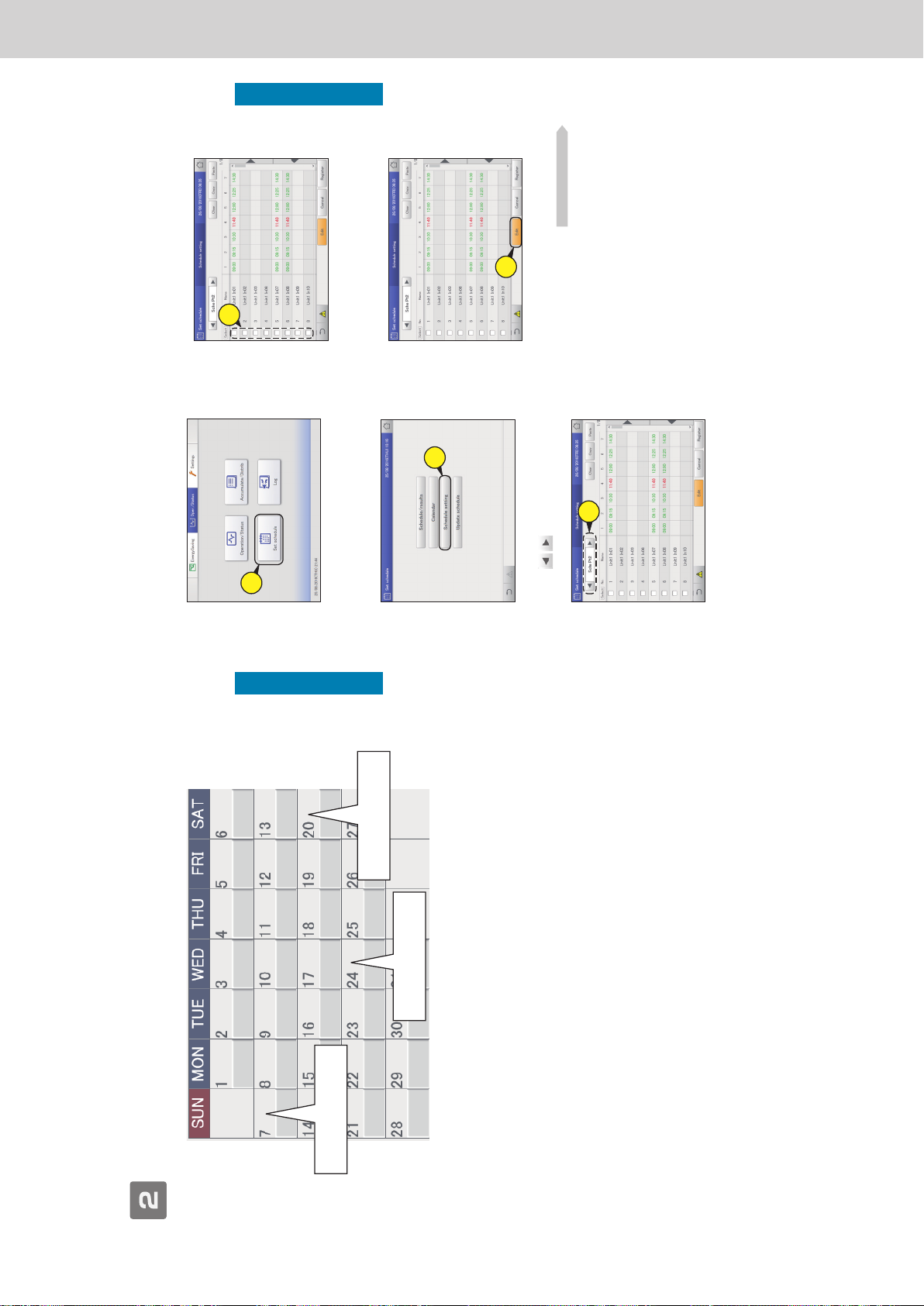
Operating Instructions Intelligent Controller
42
Setting a schedule
Operation/Status
Allocating a schedule to a date on the calendar
z “Allocating a schedule to a calendar” (P.49)
This day is a Sunday, so allocate
“Mode3”
This day is a work day, so
allocate “Mode1”
This day is a Saturday, so
allocate “Mode2”
Schedule setting ow
43
Setting a schedule
Operation/Status
Setting a schedule
Register the schedules for an indoor unit or a schedule group in the “daily running mode”.
4
Put a check mark in the “Select” column.
z Select the indoor unit or schedule group you want to set.
4
5
Touch [Edit].
z The “Detail setting” screen is displayed.
5
Continued on next page
1
Touch [Set schedule] in “Oper./Status”.
1
2
Touch [Schedule setting].
z The “Schedule setting” screen is displayed.
2
3
Press to select the daily running
mode.
3
ー 67 ー
Page 70
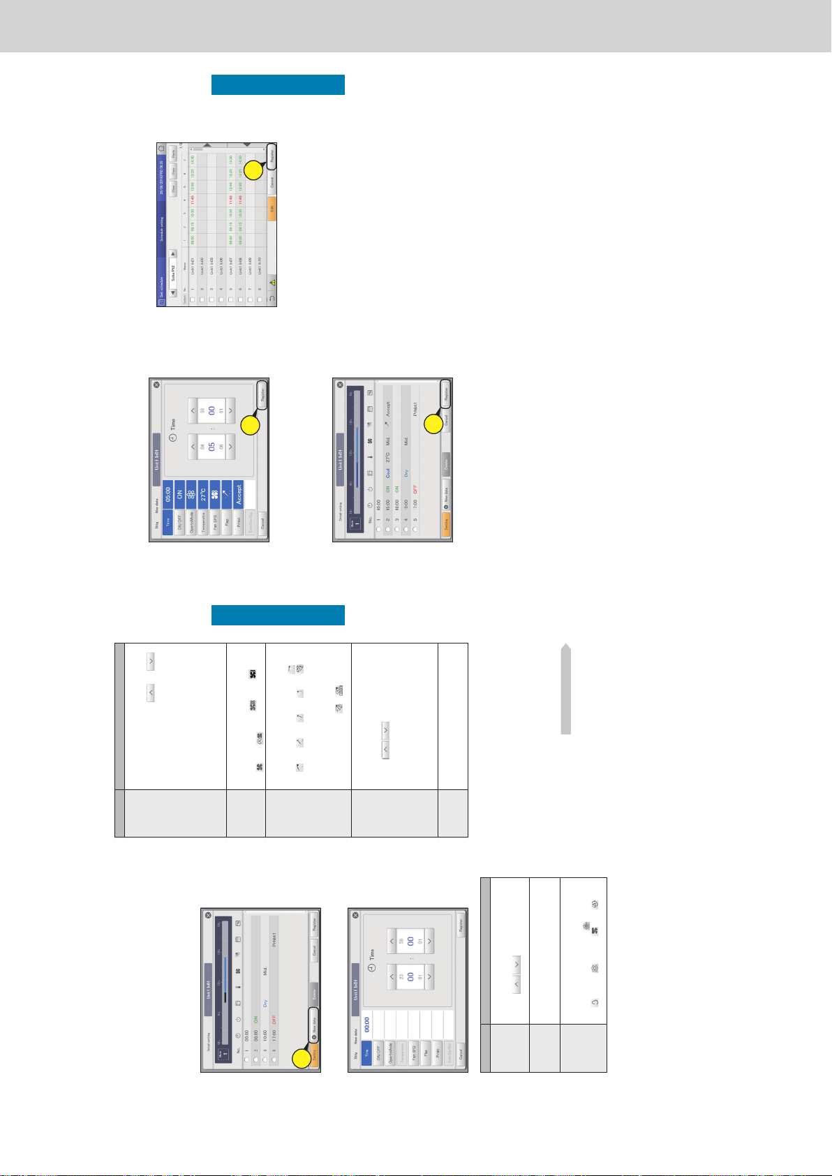
Operating Instructions Intelligent Controller
44
Setting a schedule
Operation/Status
6
Register setting cells.
z Repeat the following (1) to (3) to register setting cells.
(1) Touch [New data].
z The “Sttg” dialogue is displayed.
z In the “Sttg” dialogue, set “Time”, “ON/OFF”,
“OpertnMode”, “Temperatre”, “Fan SPD”, “Flap”, “Prhbt”,
and “EnerSavStg”.
6-
1
(2) Change the settings.
Item Explanation
Time Set the time for the operation.
1) Touch [Time].
2)
Use
to set the “hour” and
“minute”.
ON/OFF Set whether to start or stop operation.
1) Touch [ON/OFF].
2) Select “ON” or “OFF”.
OpertnMode Set the operating mode.
1) Touch [OpertnMode].
2)
Select the operating mode (
(heating),
(drying), (cooling), (fan),
(automatic)).
Item Explanation
Temperatre Set the temperature.
1) Touch [Temperatre].
2)
Set the temperature with
and .
(± in 1 °C steps)
Setting ranges
y In cooling or drying mode: Between 18 °C
and 30 °C
y In heating mode: Between 16 °C and
30 °C*
1
y Automatic: Between 17 °C and 27 °C
*1 The upper limit for gas heat pump air
conditioners is 26 °C.
Fan SPD Set the strength of the fan.
1) Touch [Fan SPD].
2)
Select the fan speed (
(high), (mid),
(low), (automatic)).
Flap Set the direction of the airow.
1) Touch [Flap].
2)
Set the ap to the desired position (
(F1),
(F2), (F3), (F4), (F5),
(Swing)).
y Heating, fan, and automatic (heating) can
be adjusted in 5 steps and cooling and dry
can be adjusted in 3 steps.
y You can set either
or if the model
does not support airow direction settings.
Prhbt Set whether to allow or prohibit use of the local
remote controller.
1) Touch [Prhbt].
2)
Use
to select from “Accept”,
“Prhbt1”, “Prhbt2”, “Prhbt3”, or “Prhbt4”.
Accept: Allows operations with the remote
controller.
Prhbt1 to Prhbt4: Operations on the remote
controller are restricted. You can change the
restricted operations. (P.185)
EnerSavStg Enable or disable energy saving operation.
1) Touch [EnerSavStg].
2) Select “Valid” or “Invl”.
Note
y You do not have to set all items, but “Time” must be set.
y You can register up to 50 setting cells per day for a single
indoor unit or single schedule group.
y When setting schedule groups, you can only set those
items that are common to the indoor units that make up the
group.
Continued on next page
Setting a schedule
45
Setting a schedule
Operation/Status
9
Touch [Register].
z A conrmation message appears.
z To cancel the settings, touch [Cancel].
9
10
Touch [OK].
z The setting is registered.
z The conrmation message “Change sched. for the next
day to 4 days later?” may be displayed.
To overwrite the setting touch [OK]. To change, touch
[Cancel].
Note
y Indoor units or schedule groups whose setting cells are all
blank will not run at all.
(3) Touch [Register].
z The settings are registered and the “Sttg” dialogue closes.
z To cancel the settings, touch [Cancel].
6-
3
7
Touch [Register].
z The “Detail setting” dialogue closes.
z To cancel the settings, touch [Cancel].
7
8
Repeat steps 4 to 7 to register other
indoor units.
z Repeat steps 3 to 7 if you want to register in other daily
running modes.
z The conrmation message “Change sched. for the next
day to 4 days later?” may be displayed.
To overwrite the setting touch [OK]. To change, touch
[Cancel].
Setting a schedule
ー 68 ー
Page 71
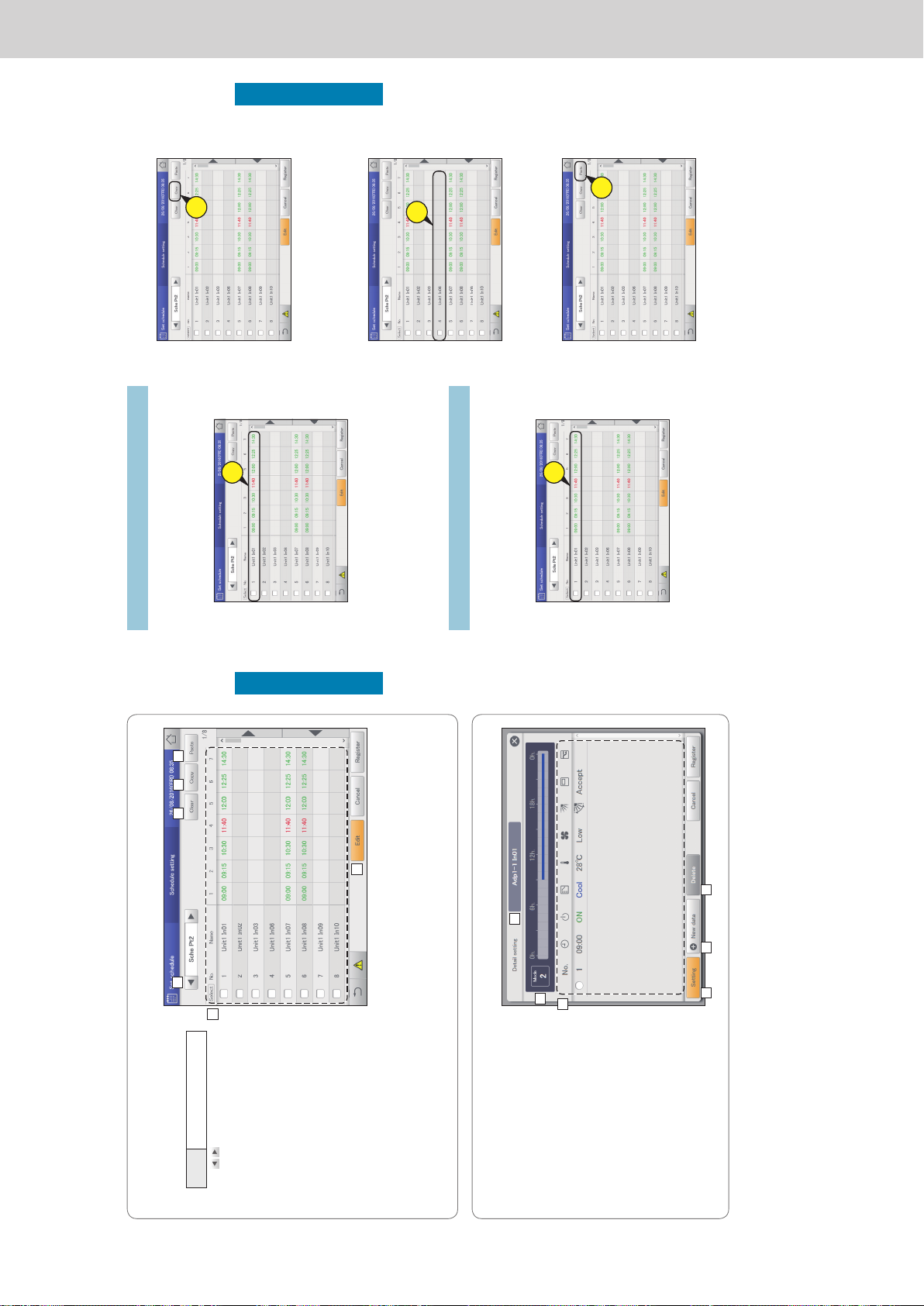
Operating Instructions Intelligent Controller
46
Setting a schedule
Operation/Status
The “Schedule setting” screen
A: Select the daily running mode to register.
You can select daily running modes from the
following types.
Mode Register as a normal pattern.
(Mode1 to 50)
y Use
to select the daily running mode.
y The display order is as follows.
“Mode1” “Mode2”
…
“Mode50”
B: You can delete the selected schedule either
by indoor unit or by schedule group.
(→ “Deleting a schedule” (P.47))
C: You can copy the selected schedule either
by indoor unit or by schedule group. (→
“Copy a schedule for setting” (P.47))
D: You can paste the schedule specied at C to
an indoor unit or schedule group.
(→ “Copy a schedule for setting” (P.47))
E: You can view the schedule for a single day
in a list.
You can scroll up or down by swiping or
icking the screen.
Note
y Before setting an operating schedule, the setting cell on the right is blank.
y When at least one check mark has been put in the “Valid” column in the “Set schedule group name” screen (refer to “Changing
the name of the schedule group” (P.151)), the schedule group name is displayed rst, then the indoor unit names that do not
belong to schedule groups are displayed.
F: The “Detail setting” dialogue is displayed when you touch this, and you can make advanced settings for the schedule.
A
C DB
E
F
The “Detail setting” dialogue
A: The name of the selected indoor unit or
schedule group is displayed.
B: The daily running mode is displayed.
Set schedules are displayed in a timetable.
C: View a list of registered setting cells.
Each line is one setting cell.
You can scroll up or down by swiping or icking
the screen.
D: Modify the registered content of setting cells.
(→ “Changing the settings in setting cells”
(P.48))
E: The “Sttg” dialogue is displayed when you
touch this and you can add setting cells.
F: Delete the registered content of setting cells.
(→ “Deleting the settings in setting cells” (P.48))
A
C
D
B
E F
Setting a schedule
47
Setting a schedule
Operation/Status
Deleting a schedule
1
Select the schedule to delete.
z The highlighted indoor unit or schedule group is the one to
be deleted.
z You cannot delete multiple indoor units or schedule groups.
1
2
Touch [Clear].
z The selected schedule is deleted.
z The schedule is restored if you touch [Cancel].
Copy a schedule for setting
This is convenient when setting the same kind of schedule.
1
Select the schedule to copy.
z The highlighted indoor unit or schedule group is the one to
be copied.
1
2
Touch [Copy].
2
3
Select the indoor unit or schedule group
you want to paste.
z You cannot simultaneously paste multiple indoor units or
schedule groups.
3
4
Touch [Paste].
z The selected schedule is pasted.
4
Setting a schedule
ー 69 ー
Page 72
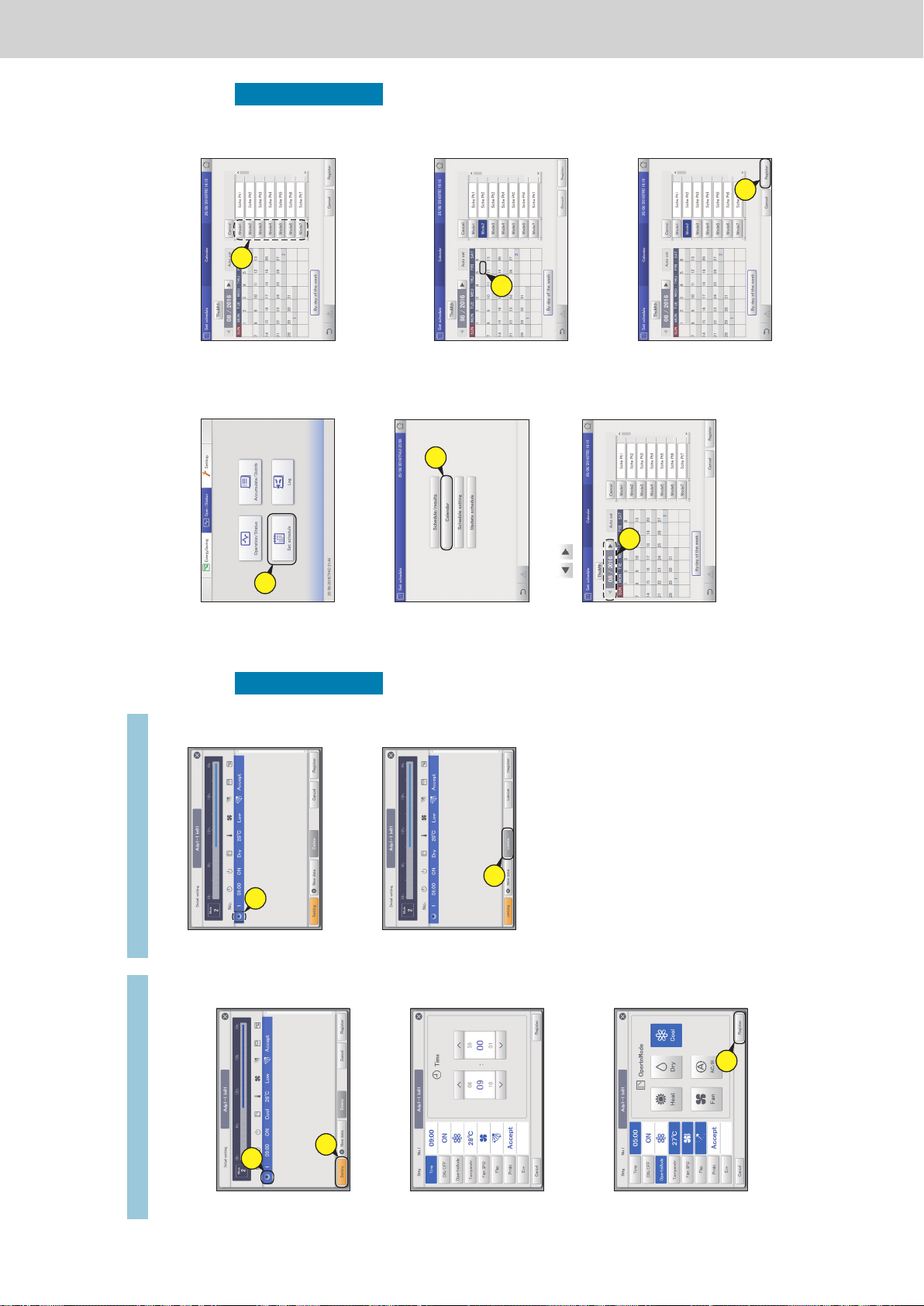
Operating Instructions Intelligent Controller
48
Setting a schedule
Operation/Status
Changing the settings in setting cells
1
Select the setting cell to be changed
(1-1) in the “Detail setting” dialogue and
touch [Setting] (1-2).
z The “Sttg” dialogue is displayed.
1-
1
1-
2
2
Change the settings.
z Refer to step 6 on P.44 for the settings.
3
Touch [Register].
z The settings are registered and the “Sttg” dialogue closes.
z To cancel the settings, touch [Cancel].
3
Setting a schedule
Deleting the settings in setting cells
1
Select the setting cell to be deleted in
the “Detail setting” dialogue.
1
2
Touch [Delete].
z The selected setting cell is deleted.
2
49
Setting a schedule
Operation/Status
Allocating a schedule to a calendar
Allocate daily running modes to a calendar.
Calendars can be set starting with the current month and up to 2 years in the future.
4
Select the daily running mode.
4
5
Touch the date.
z The daily running mode is allocated to the selected date.
z While a daily running mode is selected, you can allocate it
to other dates.
z Repeat steps 4 and 5 to allocated daily running modes to
other dates.
5
6
Touch [Register].
z The setting is registered.
z To cancel the settings, touch [Cancel].
6
1
Touch [Set schedule] in “Oper./Status”.
1
2
Touch [Calendar].
z The “Calendar” screen is displayed.
2
3
Use to select the year and month.
3
ー 70 ー
Page 73
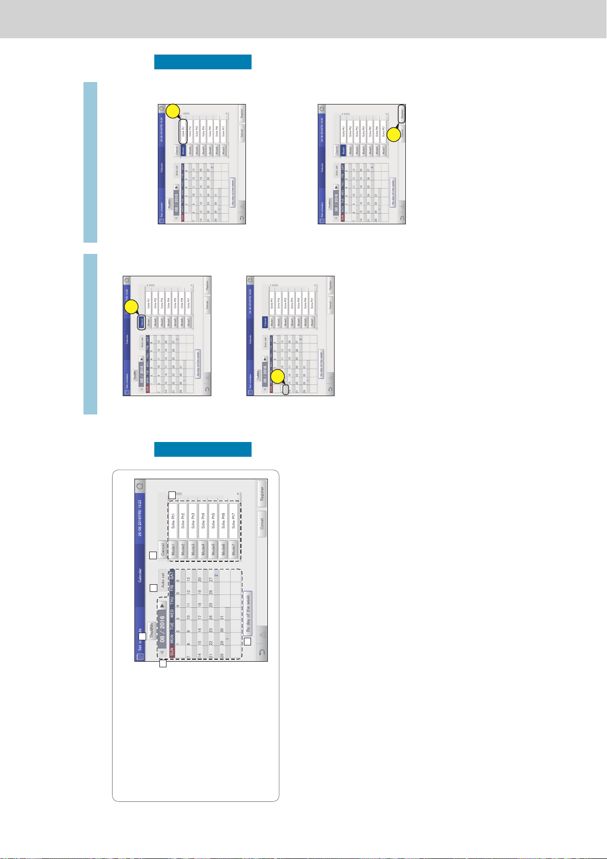
Operating Instructions Intelligent Controller
50
Setting a schedule
Operation/Status
The “Calendar” screen
A: Returns the calendar display to the current
month.
B: The calendar for the specied year and month
is displayed.
C: Automatic update is executed.
D: Delete the daily running mode allocated to a
calendar. (→ “Deleting allocated daily running
modes” (P.51))
E: A list of daily running modes allocated to the
calendar is displayed. You can put comments
in the text boxes on the right. (→ “Adding
comments to daily running modes” (P.51))
F: Allocate modes by day of the week.
(→ “Allocating by day of the week” (P.52))
A
C
B
D
E
F
Allocating a schedule to a calendar
Note
y You cannot allocate daily running modes to dates in the past.
51
Setting a schedule
Operation/Status
Deleting allocated daily running modes
1
Touch [Cancel].
1
2
Touch the date of the daily running mode
to be deleted.
2
Adding comments to daily running modes
It can be helpful to add a comment to the daily running mode to
describe how it is used, for example.
The comment can be up to 16 characters long using letters and
numbers.
1
Touch the text box on the right of the
daily running mode.
z The touchscreen keyboard is displayed.
1
2
Enter the text.
3
Touch [Register].
z The setting is registered.
z To cancel the settings, touch [Cancel].
3
Allocating a schedule to a calendar
ー 71 ー
Page 74
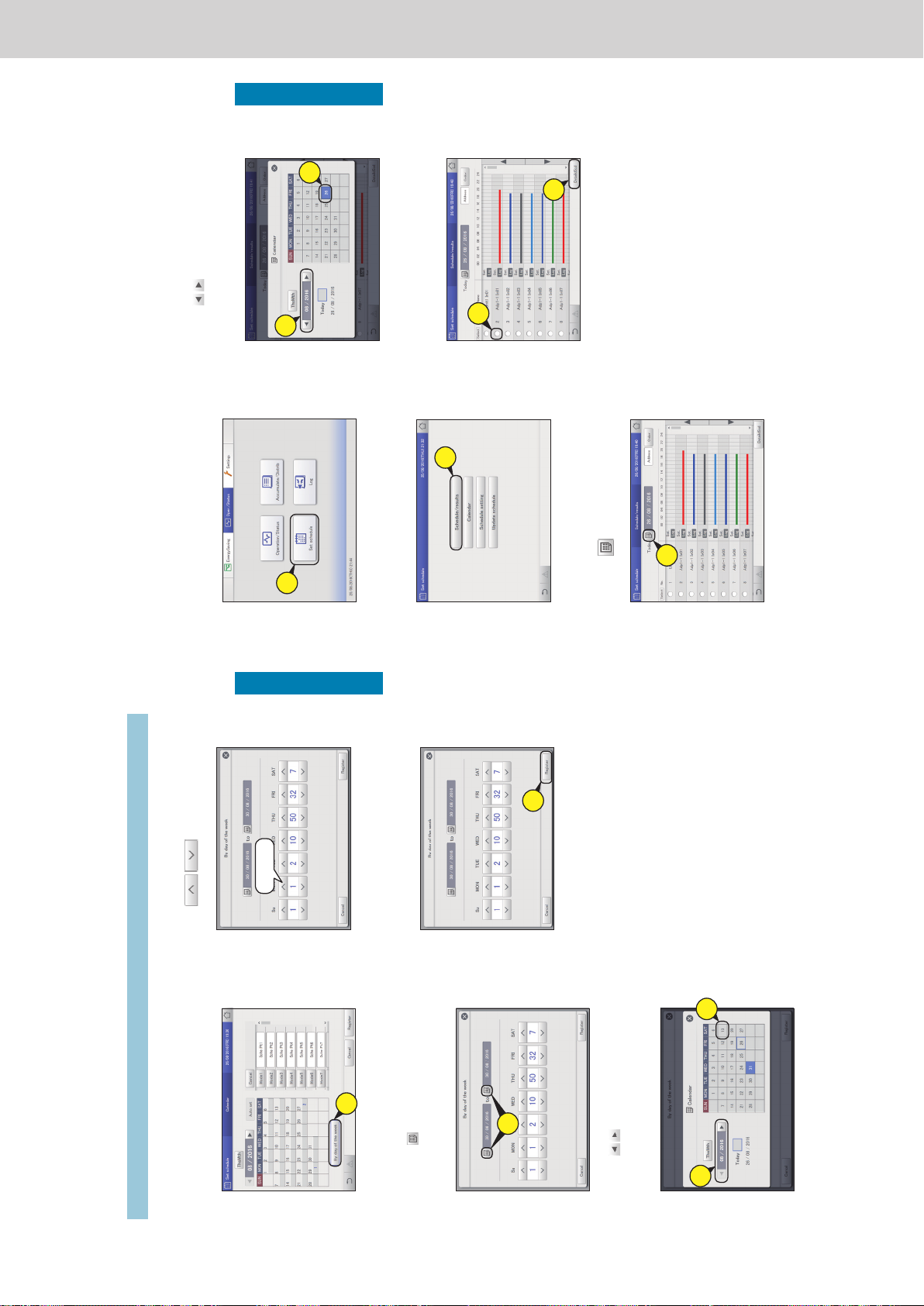
Operating Instructions Intelligent Controller
52
Setting a schedule
Operation/Status
3
Use to allocate the daily
running modes to days of the week.
Sche Pt1
4
Touch [Register].
z The setting is registered.
z To cancel the settings, touch [Cancel].
4
Note
y You cannot allocate daily running modes by day of the week to the
current day, the next day, or the day after the next day.
y You do not need to set daily running modes in every day of the
week.
y You do not need to touch [Register] or [Cancel] in the “Calendar”
screen.
y If daily running modes have already been registered in the
calendar, then when you set at the day of the week level, the daily
running modes are overwritten.
1
Touch [By day of the week].
z The “By day of the week” screen is displayed.
1
2
Set the period.
(1) Touch (2-1).
z The “Calendar” dialogue is displayed.
z The period at the left is the start and the period at the right
is the end.
2-
1
(2) Use to select the month to be set
(2-2), then select the day to be set (2-3).
z The settings are registered and the “Calendar” dialogue
closes.
2-
3
2-
2
Allocating by day of the week
Allocate daily running modes by day of the week.
Allocating a schedule to a calendar
53
Setting a schedule
Operation/Status
Checking the future schedule and past
performance
You can see the registered schedules in a list.
You can also see how operations performed in the past.
(2) Use
to select the month to be set
(3-2), then select the date (3-3).
z The settings are registered and the “Calendar” dialogue
closes.
3-
3
3-
2
4
Touch the “Select” column (4-1), then
touch [DetaildScd] (4-2).
z The “Detailed schedule” dialogue (P.54) is displayed.
4-
1
4-
2
1
Touch [Set schedule] in “Oper./Status”.
1
2
Touch [Schedule/results].
z The “Schedule/results” screen for that day is displayed.
2
3
Set the day you want to check.
(1) Touch (3-1).
z The “Calendar” dialogue is displayed.
3-
1
ー 72 ー
Page 75
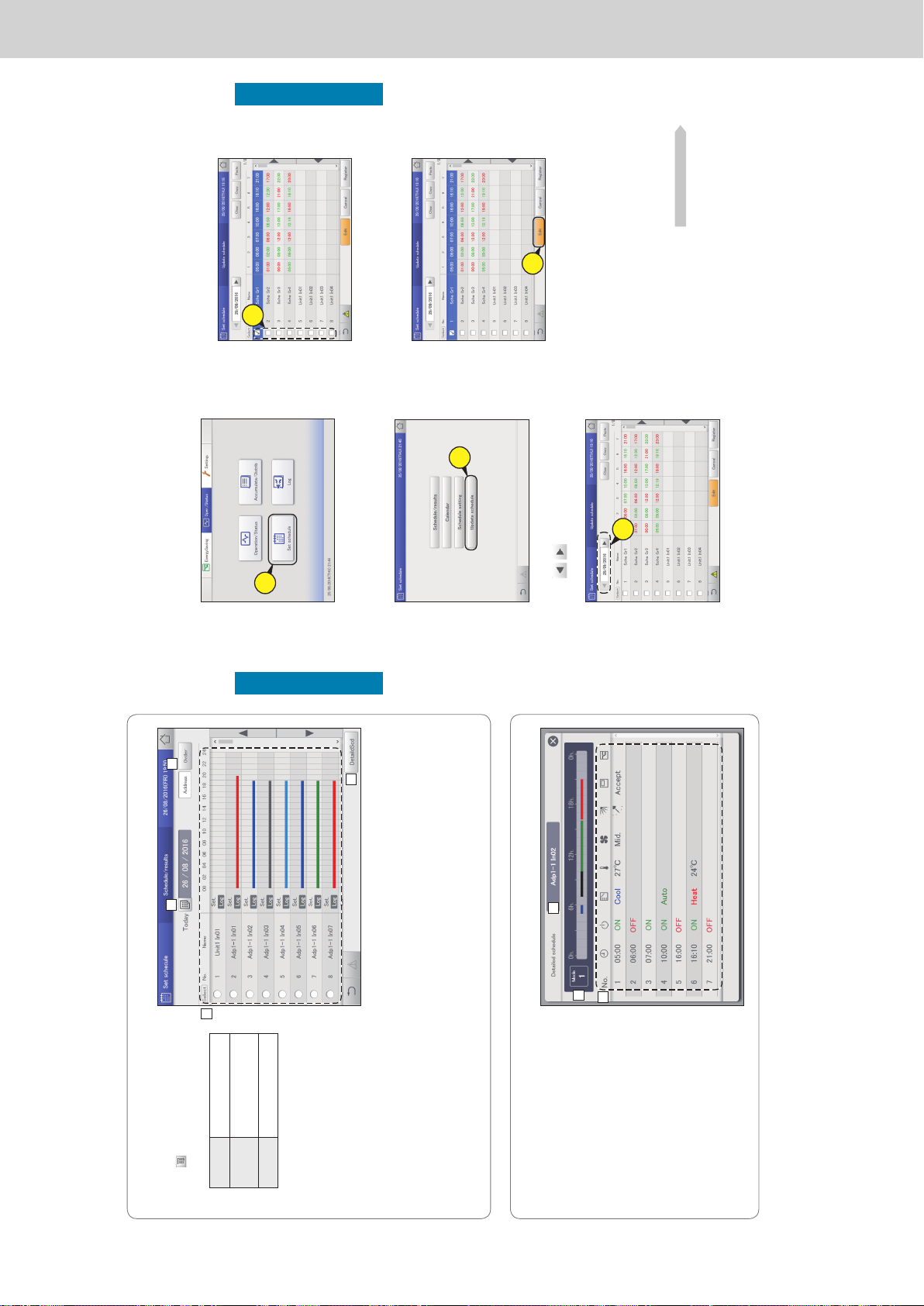
Operating Instructions Intelligent Controller
54
Setting a schedule
Operation/Status
“Schedule/results” screen
A: Select the year, month, and day to display.
The calendar screen is displayed when you
touch
and you can select the date.
B: Change list order. The list order changes
each time you touch it.
Display
The display follows the order set
in “I/D unit settings” (P.141).
O/D unit The display follows the address
order of the outdoor unit
systems.
Address The display follows the order of
the central addresses.
C: The day’s schedule and past operating
performance is displayed in a list for each
indoor unit.
The schedules are displayed in the 24-hour
format with the passage of time indicated
with a horizontal line.
The upper part of the row shows the planned
schedule and the lower part of the row
shows the past performance.
The colour key is as follows:
Blue: Cooling Light blue: Dry
Red: Warming Grey: Fan
Green: Automatic
Note
Past performance is not displayed in the following cases:
y When a date after the next day is specied in setting A
y When the power of the indoor unit has been turned off so that the schedule could not be executed
D: The “Detailed schedule” dialogue is displayed when you touch this. Details about the schedules for indoor units with a check mark
in the “Select” column are displayed.
A
B
C
D
The “Detailed schedule” dialogue
A: The name of the selected indoor unit or
schedule group is displayed.
B: The daily running mode is displayed.
The time line for a set schedule for one day is
displayed.
C: Details of B are displayed in a list.
Note
y You can check the future schedule in this screen.
Settings cannot be changed.
A
B
C
Checking the future schedule and past performance
55
Setting a schedule
Operation/Status
Temporarily modifying or adding a schedule
You can temporarily change the schedule for ve days starting with the current day and up to 4 days into
the future.
You cannot change the settings in the “Schedule setting” screen.
4
Put a check mark in the “Select” column.
z Select the indoor unit or schedule group whose settings
you want to change.
4
5
Touch [Edit].
z The “Detail setting” dialogue is displayed.
5
6
Change and add settings.
z Refer to “Changing the settings in setting cells” (P.48) to
change the settings.
z Refer to step 6 in “Setting a schedule” (P.44) to add
settings.
z Refer to step 6 in “Setting a schedule” (P.44) for the setting
items.
Continued on next page
1
Touch [Set schedule] in “Oper./Status”.
1
2
Touch [Update schedule].
z The “Update schedule” screen is displayed.
2
3
Use to select the year, month,
and day.
3
ー 73 ー
Page 76
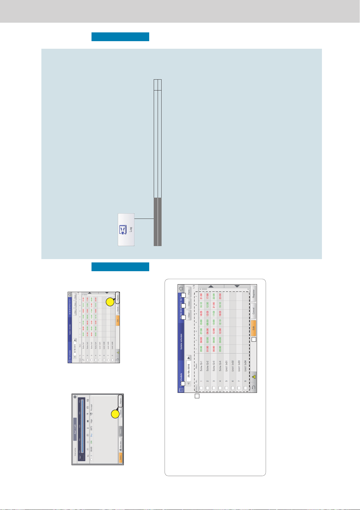
Operating Instructions Intelligent Controller
56
Setting a schedule
Operation/Status
7
Touch [Register].
z The settings are registered and the “Detail setting”
dialogue closes.
z To cancel the settings, touch [Cancel].
7
8
Touch [Register].
z The setting is registered.
z To cancel the settings, touch [Cancel].
8
Note
y Even if you change the schedule in this screen, the daily running
mode settings in the “Schedule setting” screen are not changed.
The “Update schedule” screen
A: Select the year, month, and day to change.
y Only the current day and 4 days into the
future are shown in the date.
B: You can delete the selected schedule either
by indoor unit or by schedule group.
(→ “Deleting a schedule” (P.47))
C: You can copy the selected schedule either
by indoor unit or by schedule group. (→
“Copy a schedule for setting” (P.47))
D: Paste the schedule specied at C to an
indoor unit or schedule group.
(→ “Copy a schedule for setting” (P.47))
E: View the operating schedule for a single day
in a list.
F: When you touch this, the “Detail setting”
dialogue is displayed for indoor units or
schedule groups with a check mark in the
“Select” column.
A
C DB
E
F
Temporarily modifying or adding a schedule
57
Checking the alarm logs and operation/status change logs
Operation/Status
Checking the alarm logs and operation/
status change logs
This chapter explains how to check alarm logs and operation/status change logs.
You can check the logs for alarms that have occurred in the system and the logs of operation/status changes in
lists on this unit.
You can also output the log lists in a CSV format le.
Screen menu Overview Page
Alarm log
Check the log of alarms that have occurred in the system in a list. 58
Operation/Status change log
Check the log of operation/status changes of the indoor units in a list. 61
ー 74 ー
Page 77
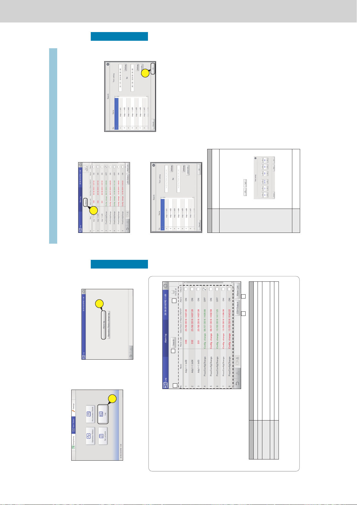
Operating Instructions Intelligent Controller
58
Checking the alarm logs and operation/status change logs
Operation/Status
Checking the alarm logs
You can display up to 100 of the most recent alarms that have occurred or that have been restored.
2
Touch [Alarm log].
z The “Alarm log” screen is displayed.
z Alarms are in red letters immediately after occurring. They
change to green letters after they are restored.
2
1
Touch [Log] in “Oper./Status”.
1
The “Alarm log” screen
A: The “Search” dialogue is displayed when you
touch this.
You can nd the log information you need from
amongst the logs for alarms that have occurred.
You can search by either the device name or the
display period. (→ “Searching alarm logs” (P.59))
B: A check mark appears in all of the “Check”
columns when you touch this.
C: The alarm log is displayed in a list.
You can scroll up or down by swiping or icking
the screen.
Item Explanation
Name The names of units where alarms are occurring are displayed.
Alarm code The type of alarm is displayed.
Date/time of Alarm ON/OFF This displays the date and time the alarm occurred. When a problem in the system has been restored, this shows
the date and time it was restored.
Alarm Immediately after an alarm has occurred, this shows “ON”, and after it is restored it shows “OFF”.
Check Select the alarms you want to check.
D: You can output (save) the displayed list of alarm logs in CSV format. (→ “Outputting (saving) logs as a CSV le” (P.60))
E: The “Alarm list” screen is displayed when you touch this. (P.35)
D
A
B
E
C
59
Checking the alarm logs and operation/status change logs
Operation/Status
1
Touch [Search].
z The “Search” dialogue is displayed.
1
2
Set the search conditions.
Item Explanation
Name Select the name of the unit for which you want
to nd the information from the list.
Term setting Set the start and nish for the period you want
to search.
The time at the top is the start of the period and
the time at the bottom is the end.
1) Touch [Settings].
y The “Date setting” dialogue is displayed.
2) Set the date and time.
y Use
to set the “Day”,
“Month”, “Year”, “Hours”, “Minutes”, and
“Seconds”.
3) Touch [OK].
y The settings are registered and the “Date
setting” dialogue closes.
y To cancel the settings, touch [Cancel].
[Latest info.] Touch to clear the period you have set and show
the most recent 100 alarms.
3
Touch [OK].
z Alarms matching the conditions are displayed in a list.
z If you specify name, the latest 200 alarms are displayed.
If you do not specify, the latest 100 alarms for all units are
displayed.
z If you specify period, the latest 200 alarms are displayed.
z You can save the search results in a le in the CSV format.
(→ “Outputting (saving) logs as a CSV le” (P.60))
z To cancel display conditions, touch [Cancel].
3
Checking the alarm logs
Searching alarm logs
ー 75 ー
Page 78

Operating Instructions Intelligent Controller
60
Checking the alarm logs and operation/status change logs
Operation/Status
4
Touch when you want to
disconnect the USB memory device.
z The message “USB memory can now be safely removed”
is displayed. Touch [OK] and then remove the USB
memory device.
z Close the storage door after removing the USB memory
device.
4
1
Open the storage door and connect
a USB memory device to the USB
terminal.
2
Touch [CSV Output].
z A conrmation screen is displayed.
2
3
Touch [OK].
z The alarm log currently displayed is saved to the USB
memory device in CSV format.
z When saving is complete, a message conrming that
saving is complete is displayed.
Checking the alarm logs
Outputting (saving) logs as a CSV le
61
Checking the alarm logs and operation/status change logs
Operation/Status
Checking the operation/status change log in a list
You can display a list showing operations for indoor units that logs when and how changes were made.
2
Touch [Operation/Status change log].
z The “Operation/Status change log” screen is displayed.
2
1
Touch [Log] in “Oper./Status”.
1
The “Operation/Status change log” screen
A: The operation log is displayed. This is
usually displayed. Touch to hide.
B: The status change log is displayed. This is
usually displayed. Touch to hide.
C: The “Search” dialogue is displayed when
you touch this.
You can nd the log information you need
from amongst the operation/status change
logs.
You can search by either the device name or
the display period. (→ “Searching operation/
status change logs” (P.62))
D: The operation/status change logs are
displayed in a list.
Item Explanation
Name The names of the units are displayed.
Operation This shows whether the operation occurred as schedule or if the operation was changed.
Status This indicates the operating status (ON or OFF).
Mode The operating mode (Heat, Dry, Cool, Fan, A/Heat, A/Cool) is displayed.
Set T. The temperature setting is displayed.
Fan The fan speed (High, Mid., Low, Auto) is displayed.
Flap The airow direction is displayed.
Prhbt This indicates the remote controller operation “Accept”, or “Prhbt1” to “Prhbt4”.
Date The date and time of the change to operational status is displayed.
E: You can output (save) the displayed list of operation/status change logs in CSV format.
(→ “Outputting (saving) logs as a CSV le” (P.63))
A
C
E
B
D
ー 76 ー
Page 79
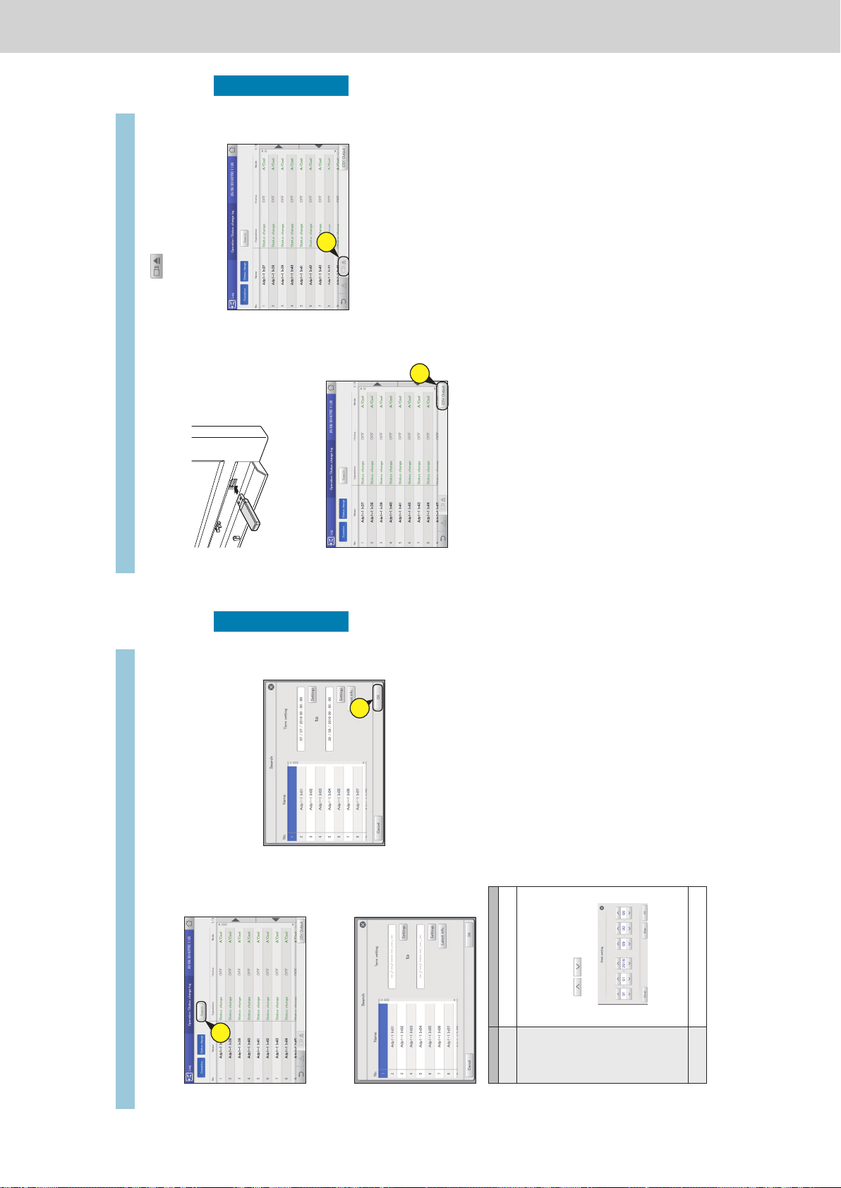
Operating Instructions Intelligent Controller
62
Checking the alarm logs and operation/status change logs
Operation/Status
3
Touch [OK].
z Operation/status change logs matching the conditions are
displayed in a list.
z If you specify device, the latest 200 operation logs are
displayed. If you do not specify the device, the latest
100 operation logs for all devices are displayed.
z If you specify period, the latest 200 operation logs are
displayed.
z You can save the search results in a le in the CSV format.
(→ “Outputting (saving) logs as a CSV le” (P.63))
z To cancel the search, touch [Cancel].
3
1
Touch [Search].
z The “Search” dialogue is displayed.
1
2
Set the search conditions.
Item Explanation
Name Select the name of the unit for which you want
to nd the information from the list.
Term setting Set the start and nish for the period you want
to search.
The time at the top is the start of the period and
the time at the bottom is the end.
1) Touch [Settings].
y The “Date setting” dialogue is displayed.
2) Set the date and time.
y Use
to set the “Day”,
“Month”, “Year”, “Hours”, “Minutes”, and
“Seconds”.
3) Touch [OK].
y The settings are registered and the “Date
setting” dialogue closes.
y To cancel the settings, touch [Cancel].
[Latest info.] Touch to clear the period you have set and show
the most recent 100 alarms.
Checking the operation/status change log in a list
Searching operation/status change logs
63
Checking the alarm logs and operation/status change logs
Operation/Status
4
Touch when you want to
disconnect the USB memory device.
z The message “USB memory can now be safely removed”
is displayed. Touch [OK] and then remove the USB
memory device.
z Close the storage door after removing the USB memory
device.
4
1
Open the storage door and connect
a USB memory device to the USB
terminal.
2
Touch [CSV Output].
z A conrmation screen is displayed.
2
3
Touch [OK].
z The log currently displayed is saved to the USB memory
device in CSV format.
z When saving is complete, a message conrming that
saving is complete is displayed.
Checking the operation/status change log in a list
Outputting (saving) logs as a CSV le
ー 77 ー
Page 80
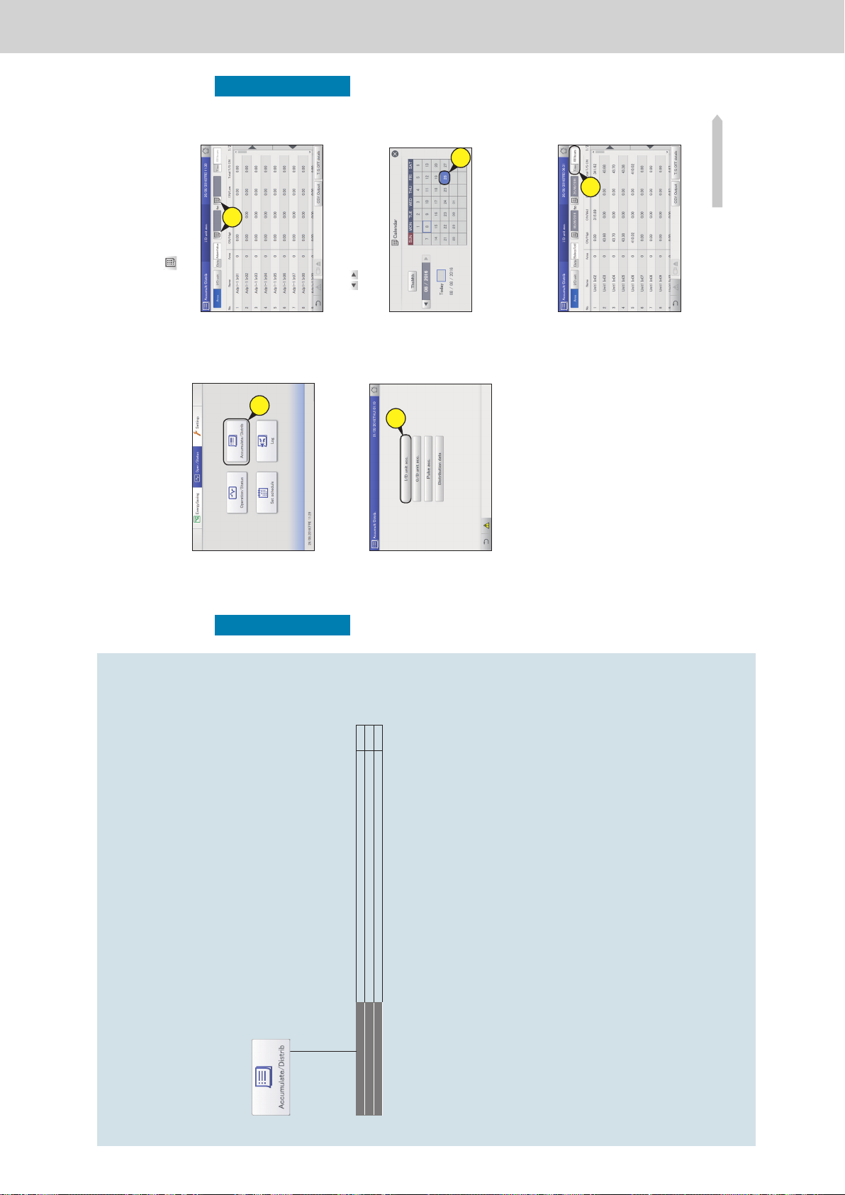
Operating Instructions Intelligent Controller
64
Check accumulated values
Operation/Status
Check accumulated values
This chapter explains how to check the accumulated values for the devices.
You can check accumulated values for indoor units, outdoor units, and pulse meters in a list on this unit.
The display for indoor units can be viewed by area or individual unit, and outdoor units and pulse meters can be
viewed by different values (adaptor value or total value for a period).
Screen menu Overview Page
I/D unit acc.
Check the accumulated data for the indoor units in a list. 65
O/D unit acc.
Check the accumulated data for the outdoor units in a list. 67
Pulse acc.
Check the accumulated data for the pulse meters in a list. 69
65
Check accumulated values
Operation/Status
Checking the list of accumulated values on
the indoor unit
The accumulated values for indoor units (thermostat ON operating times, etc.) are displayed in a list.
1
Touch [Accumulate/Distrib] in “Oper./
Status”.
1
2
Touch [I/D unit acc.].
z The “I/D unit acc.” screen is displayed.
2
3
Set the period to be displayed.
z Set the start and end of the period to be displayed.
z The time at the left is the start of the period and the time at
the right is the end.
z If you set “Data” to “Adaptor value”, you cannot select the
period to be displayed.
(1) Touch (3-1).
z The “Calendar” dialogue is displayed showing the current
date.
3-
1
(2) Touch the date (3-2).
z Use to select the month you want to check. The
current month is displayed if you touch [ThsMth].
z The settings are registered and the “Calendar” dialogue
closes.
3-
2
4
Set the time slots to display.
(1) Touch [Time] (4-1).
z The “Specify time” dialogue is displayed.
z If you set “Data” to “Adaptor value”, you cannot select the
time slots to be displayed.
4-
1
Continued on next page
ー 78 ー
Page 81
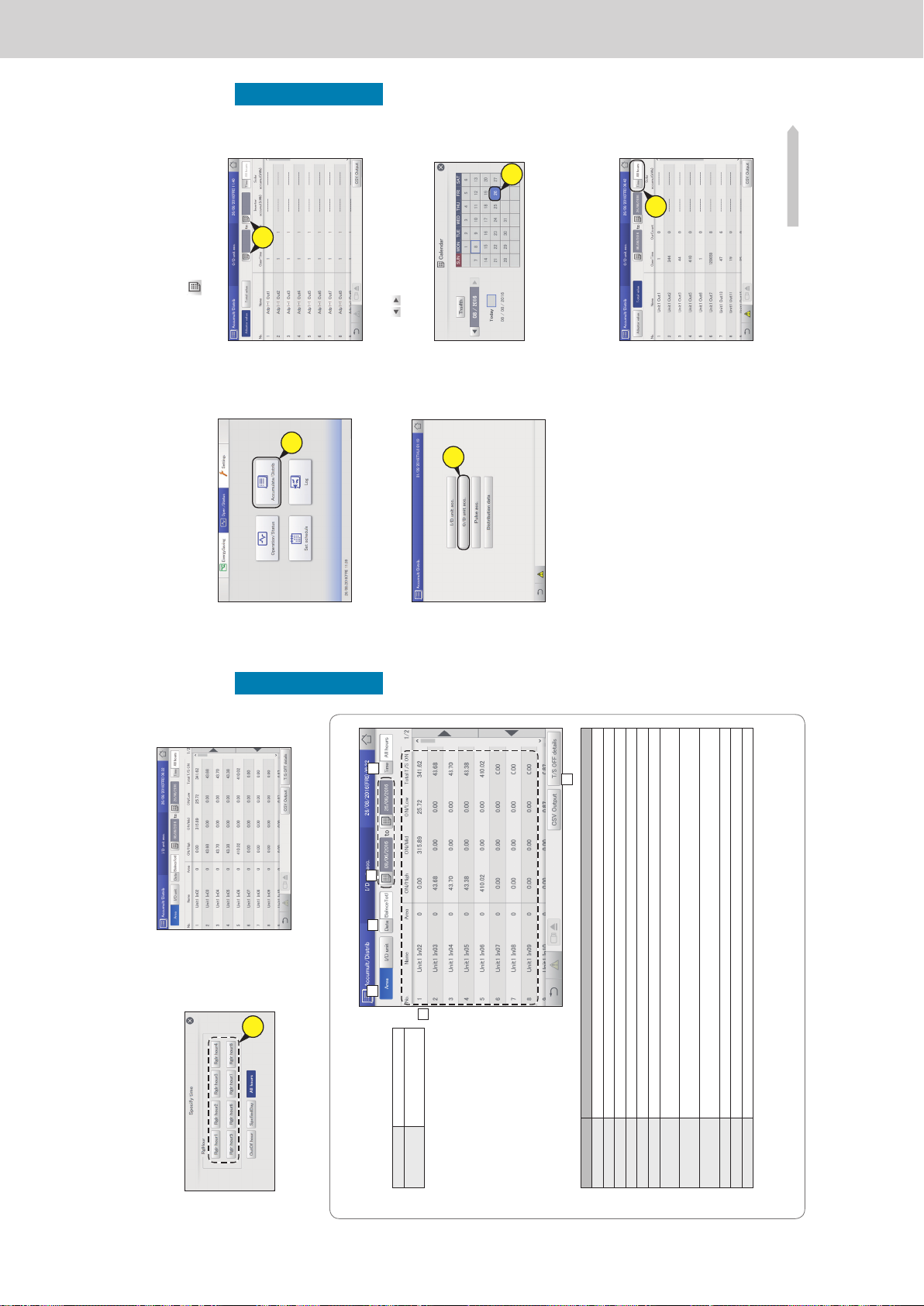
Operating Instructions Intelligent Controller
66
Check accumulated values
Operation/Status
The “I/D unit acc.” screen
A: Set the order of display.
[Area] Display indoor units by area.
[I/D unit] Display indoor units in display
order.
B: Set the displayed values. The “Data type”
dialogue is displayed when you touch this.
Select from “Adaptor value”, “Balance total”,
or “WeighFactrBlnceTtl”.
C: Set the periods to be displayed. The
“Calendar” dialogue is displayed when you
touch this.
D: Set the time slots to be displayed. The
“Specify time” dialogue is displayed when
you touch this.
E: The accumulated values for indoor units are
displayed in a list.
You can scroll up or down by swiping or
icking the screen.
Item Explanation
Name The names of the indoor units are displayed.
Area The area number that the indoor unit belongs to is displayed.
ON/High Displays the accumulated operating hours when the thermostat is “ON” and the fan is set to “High”.
ON/Mid Displays the accumulated operating hours when the thermostat is “ON” and the fan is set to “Mid.”.
ON/Low Displays the accumulated operating hours when the thermostat is “ON” and the fan is set to “Low”.
Total T/S ON The total value of accumulated operating hours when the thermostat is “ON” and when “ON/High”, “ON/Mid”, and “ON/Low”.
OFF/High Displays the accumulated hours when the thermostat is “OFF” and the fan is set to “High”. (When [T/S OFF details] is
touched)
OFF/Mid Displays the accumulated hours when the thermostat is “OFF” and the fan is set to “Mid.”. (When [T/S OFF details] is
touched)
OFF/Low Displays the accumulated hours when the thermostat is “OFF” and the fan is set to “Low”. (When [T/S OFF details] is
touched)
Total T/S OFF Displays the accumulated hours when the thermostat is “OFF”.
Elec Htr ON Displays the accumulated hours when the heater is “ON”. (When [T/S OFF details] is touched)
T/S ON + T/S OFF Displays all the accumulated operating hours.
F: The “OFF/High ”, “OFF/Mid”, “OFF/Low”, and “Elec Htr ON” items are added to the display when you touch this. Touch again to
return to the items displayed previously.
A
C
D
B
F
E
5
Check accumulated values.
Checking the list of accumulated values on the indoor unit
(2) Touch the time slot to accumulate (4-2).
z The settings are registered and the “Specify time” dialogue
closes.
z Refer to “RglrHourRnge” in “Calendr sttgs for distr calc”
(P.148) for information about “Rglr hour1” to “Rglr hour8”.
4-
2
67
Check accumulated values
Operation/Status
Checking the list of accumulated values on
the outdoor unit
The accumulated values for outdoor units (engine operating times, engine operation cycles, etc.) are
displayed in a list.
(1) Touch
(3-1).
z The “Calendar” dialogue is displayed showing the current
date.
3-
1
(2) Touch the date (3-2).
z Use to select the month you want to check. The
current month is displayed if you touch [ThsMth].
z The settings are registered and the “Calendar” dialogue
closes.
3-
2
4
Set the time slots to display.
(1) Touch [Time] (4-1).
z The “Specify time” dialogue is displayed.
z If you set the “Adaptor value”, you cannot select the time
slots to be displayed.
4-
1
Continued on next page
1
Touch [Accumulate/Distrib] in “Oper./
Status”.
1
2
Touch [O/D unit acc.].
z The “O/D unit acc.” screen is displayed.
2
3
Set the period to be displayed.
z Set the start and end of the period to be displayed.
z The time at the left is the start of the period and the time at
the right is the end.
z If you set the “Adaptor value”, you cannot select the period
to be displayed.
ー 79 ー
Page 82
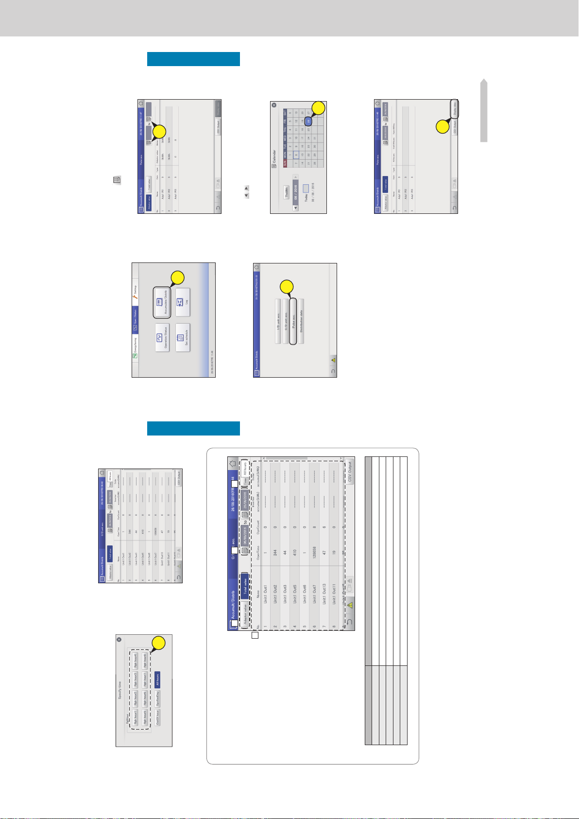
Operating Instructions Intelligent Controller
68
Check accumulated values
Operation/Status
The “O/D unit acc.” screen
A: Set the values to be displayed. Touch to
select either “Adaptor value” or “Total value”.
B: Set the periods to be displayed. The
“Calendar” dialogue is displayed when you
touch this.
y When “Total value” is set, totals matching
the time slot set in “Time” (“RglHour”,
“OutOf hour”, etc.) are displayed. If “All
hours” is set in “Time”, all totals are
displayed.
C: Set the time slots to be displayed. The
“Specify time” dialogue is displayed when
you touch this.
D: The accumulated values for outdoor units
are displayed in a list.
You can scroll up or down by swiping or
icking the screen.
Item Explanation
Name The names of the outdoor units are displayed.
OperTime The number of operation hours for the outdoor units are displayed.
OprCount The number of operation cycles for the outdoor units are displayed.
Inverter accumul.(kWh) The accumulated values if inverter generation is being used are displayed.
Solar accumul.(kWh) The accumulated values if solar generation is being used are displayed.
A B C
D
5
Check accumulated values.
Checking the list of accumulated values on the outdoor unit
(2) Touch the time slot to accumulate (4-2).
z The settings are registered and the “Specify time” dialogue
closes.
z Refer to “RglrHourRnge” in “Calendr sttgs for distr calc”
(P.148) for information about “Rglr hour1” to “Rglr hour8”.
4-
2
69
Check accumulated values
Operation/Status
Checking the list of accumulated values on
a pulse meter
The accumulated pulse count values for the pulse meter are displayed in a list. (When a pulse meter is set)
1
Touch [Accumulate/Distrib] in “Oper./
Status”.
1
2
Touch [Pulse acc.].
z The “Pulse acc.” screen is displayed.
2
3
Set the period to be displayed.
z Set the start and end of the period to be displayed.
z The time at the left is the start of the period and the time at
the right is the end.
z If you set the “Adaptor value”, you cannot select the period
to be displayed.
(1) Touch (3-1).
z The “Calendar” dialogue is displayed showing the current
date.
3-
1
(2) Touch the date (3-2).
z Use to select the month you want to check. The
current month is displayed if you touch [ThsMth].
z The settings are registered and the “Calendar” dialogue
closes.
3-
2
4
Select the display item.
(1) Touch [Display data] (4-1).
z The “Display data” dialogue is displayed.
4-
1
Continued on next page
ー 80 ー
Page 83
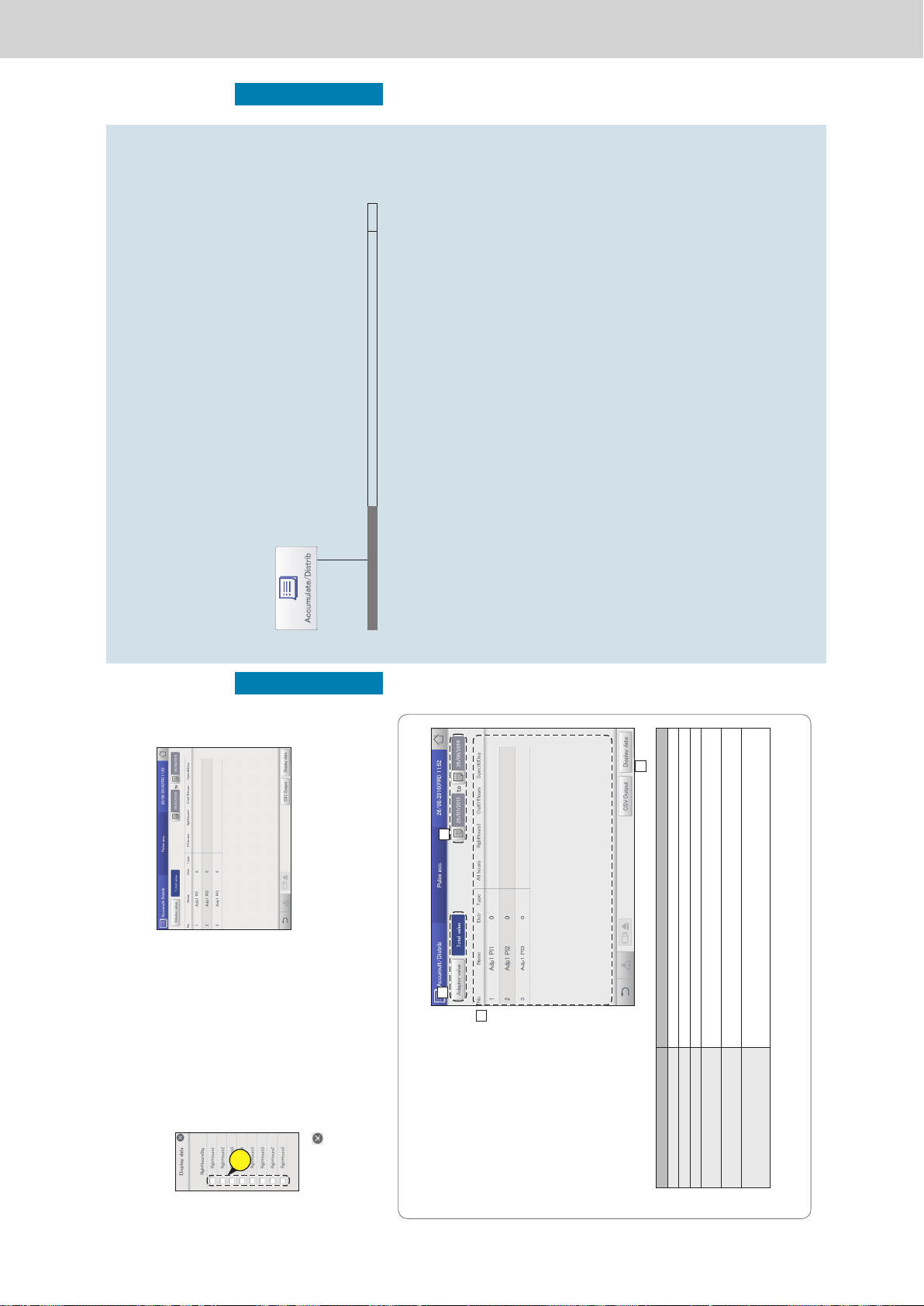
Operating Instructions Intelligent Controller
70
Check accumulated values
Operation/Status
5
Check accumulated values.
(2) Select the items to be displayed (4-2).
z You can select multiple items.
z Refer to “RglrHourRnge” in “Calendr sttgs for distr calc”
(P.148) for information about “RglrHours1” to “RglrHours8”.
4-
2
(3) Touch .
z The settings are registered and the “Display data” dialogue
closes.
Checking the list of accumulated values on a pulse meter
The “Pulse acc.” screen
A: Set the values to be displayed. Touch to
select either “Adaptor value” or “Total value”.
y If you set “Adaptor value”, the displayed
value changes at 10-second intervals.
B: Set the periods to be displayed. The
“Calendar” dialogue is displayed when you
touch this.
y When “Total value” is set, totals matching
the time slot set in “Time” (“RglrHours”,
“OutOfHours”, etc.) are displayed.
C: The accumulated values for pulse meters
are displayed in a list.
You can scroll up or down by swiping or
icking the screen.
Item Explanation
Name The names of all units (indoor units and outdoor units) are displayed.
Dstr The distribution group number is displayed.
Type The type of meter is displayed.
Adaptor value (when “Adaptor value” is
selected)
The accumulated value of the communication adaptor is displayed.
Meter value (when “Adaptor value” is
selected)
The accumulated value for pulse meter is displayed.
Time (when “Total value” is selected) The accumulated pulse count values for the adaptor or specied period are displayed. (“All hours”,
“OutOfHours”, “SpecifdDay”)
Display items (“RglrHours1” to “RglrHours8”) can also be added.
D: The “Display data” dialogue is displayed when you touch this, and you can select the items to add to the display.
y If you set the “Adaptor value”, you cannot select the items to be displayed.
A
B
D
C
71
Checking distribution data
Operation/Status
Checking distribution data
This chapter explains how to check distribution data.
You can check distribution data in a list by unit and by area on this unit.
You can check the distribution ratio, usage, and charges for both electricity and gas.
Screen menu Overview Page
Distribution data
Check the details about distribution calculations in a list. 72
ー 81 ー
Page 84
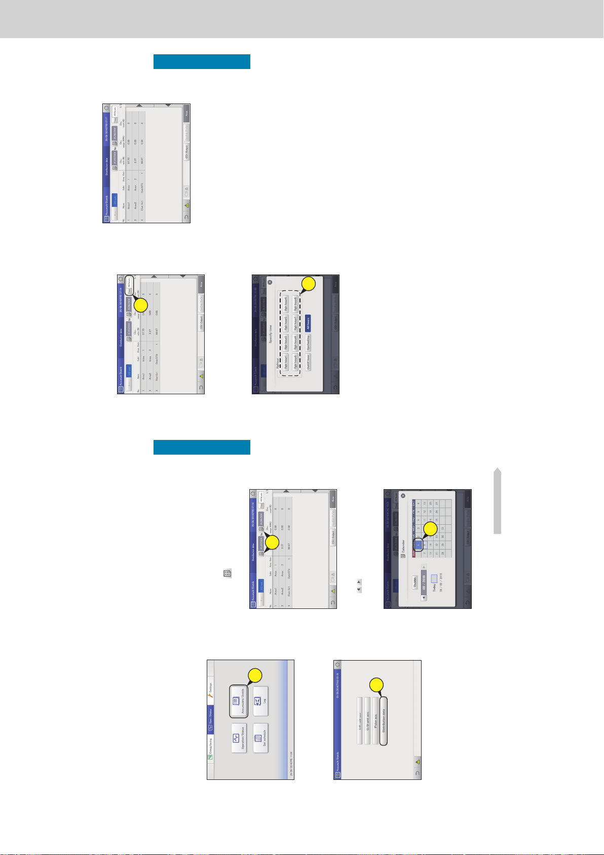
Operating Instructions Intelligent Controller
72
Checking distribution data
Operation/Status
Checking distribution data in a list
Details about distribution data (distribution ratios, usage, and charges) are displayed in a list.
For indoor units used in tenanted buildings, it can be difcult to know how much electricity or gas is used
in each area because the same air conditioning system may be used across multiple areas.
By putting the indoor units in each area into “Distribution group”, rates can be calculated based on the
data acquired from the air conditioning units (indoor units and outdoor units) in a “Distribution group”,
and this can help you know how much electricity or gas is used in each area. The rate calculated by this is
called the “Distribution ratio”.
You need to make the following settings before you can check distribution data.
y Distribution mode settings (P.160)
y Area group name settings (P.153)
y Distribution group settings (P.155)
y Pulse meter settings (P.158)
y Calendar settings for distribution calculation (P.148)
y Distribution ratio settings (P.161)
3
Set the period to be displayed.
z Set the start and end of the period to be displayed.
z The time at the left is the start of the period and the time at
the right is the end.
(1) Touch (3-1).
z The “Calendar” dialogue is displayed showing the current
date.
3-
1
(2) Touch the date (3-2).
z Use to select the month you want to check. The
current month is displayed if you touch [ThsMth].
z The settings are registered and the “Calendar” dialogue
closes.
3-
2
Continued on next page
1
Touch [Accumulate/Distrib] in “Oper./
Status”.
1
2
Touch [Distribution data].
z The “Distribution data” screen is displayed.
2
73
Checking distribution data
Operation/Status
4
Set the time slots to display.
(1) Touch [Time] (4-1).
z The “Specify time” dialogue is displayed.
4-
1
(2) Touch the time slot to accumulate (4-2).
z Refer to “RglrHourRnge” in “Calendr sttgs for distr calc”
(P.148) for information about “Rglr hour1” to “Rglr hour8”.
z The settings are registered and the “Specify time” dialogue
closes.
4-
2
5
Checking distribution data.
Note
y The calculations for distribution made by this unit do not accord with the relevant laws and statutes, so they cannot be used for ofcial
transactions.
y The operating time data accumulated on the indoor units is acquired via a communication adaptor. When this unit sends a request for the
data to the communication adaptor, the communication adaptor makes inquiries to the indoor units about their operating hours, and when
collection is complete is transfers the results to this unit. This may result in a difference in counts when moving from one time slot to the next.
y Stopping of indoor units by scheduling is subject to some delays due to communications, so make sure it is not set at the same time as the
“RglrHourRnge stngs” (P.150) time slot is changed over. If the schedule stops operation prior to the change over of a time slot, avoid setting it
inside 10 minutes (this may change depending on the state of communications) of the change over of the time slot.
y When there is a problem with the communications between the main unit and the indoor units (or the communication adaptor), it may not
be possible to accumulate by time slot normally. The accumulated values received by this unit are counted in the time slot when they are
received.
y The usage in [All hours] in the “Specify time” dialogue is calculated from the distribution ratio distributed overall according to the total
operating data from all time slots. This means that the usages in [RglHour], [OutOf hour], and [SpcedDay] will not match.
y If you remove an air conditioning unit after accumulating distribution data, all accumulated values for that air conditioning unit are deleted, so
it will not be possible to view distribution data that includes that air conditioning unit after it is removed.
Before removing the unit, output (save) the distribution data as a CSV le to a USB memory device.
The output method for CSV les is the same as for outputting logs. (→ “Outputting (saving) logs as a CSV le” (P.60))
Checking distribution data in a list
ー 82 ー
Page 85
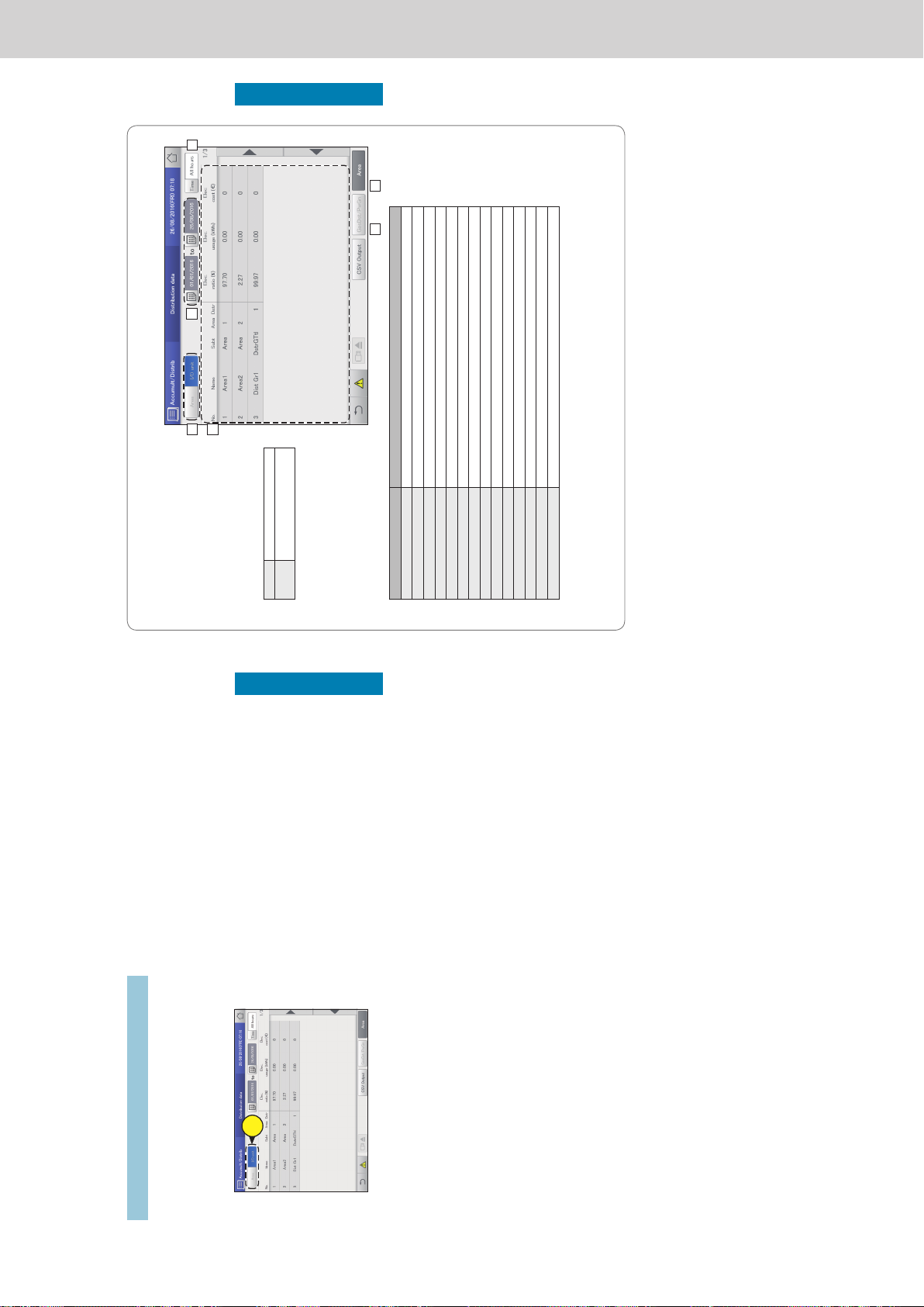
Operating Instructions Intelligent Controller
74
Checking distribution data
Operation/Status
Changing the units of display
1
Make sure that [Area] is off.
2
Select the unit of display.
z Switch the display between “Area” and “I/D unit”.
2
Checking distribution data in a list
75
Checking distribution data
Operation/Status
The “Distribution data” screen
A: Set the units of display.
[Area] Display indoor units by area.
[I/D unit] Display indoor units in display
order.
B: Set the periods to be displayed. The
“Calendar” dialogue is displayed when you
touch this.
C: Set the time slots to be displayed. The
“Specify time” dialogue is displayed when
you touch this.
D: Indoor unit distribution data is displayed in
a list.
Item Explanation
Name The names of the indoor units are displayed.
Subt This is the subtotal of the specied unit.
Area The area number that the indoor unit belongs to is displayed.
Dstr The distribution group number is displayed.
Elec. ratio (%) This is the distribution ratio of electricity supplied from outdoor units.
Elec. usage (kWh) This is the usage of electricity supplied from outdoor units.
Elec. cost This is the charges calculated based on the electricity usage.
O/D Gas ratio(%) This is the distribution ratio of gas supplied from GHP.
O/D Gas usage(m3) This is the quantity of gas supplied from GHP.
O/D Gas cost This is the charges calculated based on the gas usage.
PwrGnGas ratio(%) This is the distribution ratio of gas used to generate power.
PwrGnGas usage(m3) This is the volume of gas used to generate power.
PwrGnGas cost This is the charges calculated based on the volume of gas used to generate power.
Total cost This is the total of “Elec. cost”, “O/D Gas cost”, and “PwrGnGas cost”.
E: The “PwrGnGas ratio”, “PwrGnGas usage”, and “PwrGnGas cost” items are added to the display when you touch this. This is not
possible if time distribution is set, however.
F: Display by area or by distribution group. (Factory setting: ON)
When this is cancelled, it is possible to display by area or by indoor unit. (→ “Changing the units of display” (P.74))
A
B
D
C
E F
Checking distribution data in a list
ー 83 ー
Page 86
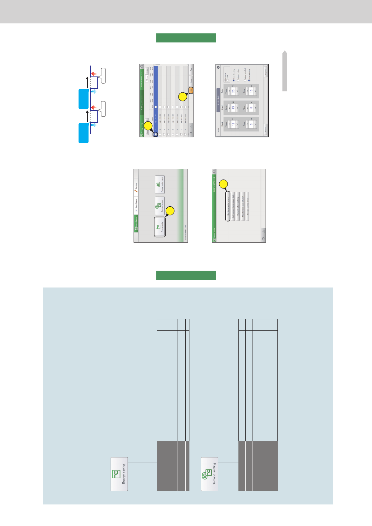
Operating Instructions Intelligent Controller
76
Settings for energy saving
Energy saving
Settings for energy saving
This chapter explains how to make energy saving settings.
This unit is equipped with the e-CUT functions (temperature auto return, unattended auto shutoff, temperature
range limit, energy saving timer/efcient operation*).
The e-CUT functions reduce waste when air conditioning so that you can even save energy using existing air
conditioning units.
Screen menu Overview Page
Set temp. auto return
Even if the temperature initially set is changed, the temperature automatically returns to
the set one after a certain amount of time.
77
Unattended auto shutoff
If the air conditioning unit automatically stops at the set time but then is started again,
this setting automatically stops the unit again repeatedly at set intervals.
80
Set temperature range limit
Restrict the temperatures that can be set by setting upper and lower limits on
temperatures.
83
Energy saving timer/Efcient
operation setting*
You can specify time slots when you want operation capacity reduced. 85
Out unit silent setting
Set a time for the outdoor unit to operate at a lower level at night compared to the day. 87
Screen menu Overview Page
I/D unit demand settings
You can automatically control indoor units by setting particular levels to cut the maximum
demand for electricity or maximum gas consumption.
89
O/D unit demand settings
You can automatically control outdoor units by setting particular levels to cut the
maximum demand for electricity or maximum gas consumption.
92
Demand/peak shaving settings/
Peak cut settings*
Limit the electricity or gas consumed by outdoor units during the set time slot. 94
O/D unit cyclic
At specied 10 minute intervals, the thermostats of outdoor units in control groups are
turned off and restored repeatedly in order.
101
I/D unit cyclic
At specied intervals (3, 4, or 5 minutes), the thermostats of indoor units in control
groups are turned off and restored repeatedly in order.
97
Register demand point
Register the demand point input. 104
* When using gas heat pump air conditioners
77
Settings for energy saving
Energy saving
Automatically return to set temperatures
[Set
temp. auto return]
Even if the set temperature is changed, the temperature automatically returns to the set temperature
(“Return temperature”) at certain times (“Return time”). This feature prevents over cooling or heating.
3
Put a check mark in the “Select” column
(3-1), and touch [Set] (3-2).
z The “Setting” dialogue is displayed.
3-
1
3-
2
4
Change the settings.
Continued on next page
1
Touch [Energy saving] in “EnergySaving”.
1
2
Touch [Set temp. auto return].
z The “Set temp. auto return” screen is displayed.
2
y When you want to keep the set temperature at 28 °C during
the summer months
Make the return temperature 28 °C in the temperature auto return
setting and the return time 30 minutes later, and it will not matter
how many times the temperature is changed, the set temperature
will return to 28 °C every 30 minutes after it is changed.
However, when the return temperature is set to 27 °C, if the set
temperature is changed to 28 °C, the temperature will not return
to the return temperature even after the return time has elapsed.
(When “Eco dirc. only” is set)
Temperature
change
Temperature
change
30 minutes
later
28 °C
22 °C
Return! Return!
30 minutes
later
ー 84 ー
Page 87
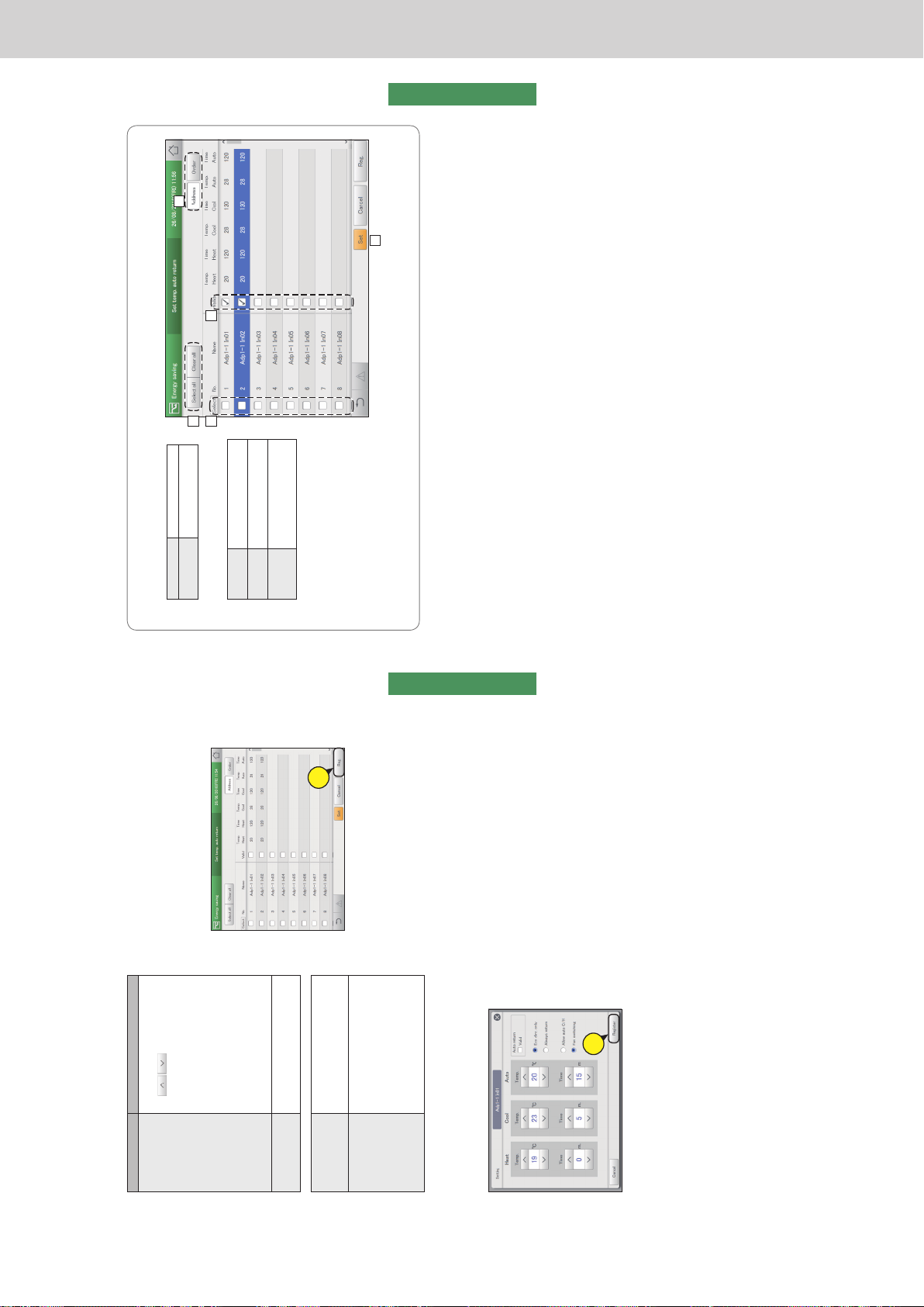
Operating Instructions Intelligent Controller
78
Settings for energy saving
Energy saving
6
Set other indoor units.
z Repeat steps 3 to 5.
7
Touch [Reg.].
z To cancel the settings, touch [Cancel].
7
Item Explanation
Return temperature
Return time
Set the return temperatures for “Heat”,
“Cool”, and “Auto” and the return time.
Use
to set the temperature
or time.
The setting ranges are as follows.
y Return temperature for heating:
16 to 30 °C*
1
(1 °C intervals)
*1 The upper limit for gas heat pumps
is 26 °C.
y Return temperature for cooling (dry):
18 to 30 °C (1 °C intervals)
y Return temperature for auto:
17 to 27 °C (1 °C intervals)
y Return time (shared):
0 to 240 minutes (5 minute intervals)
Auto return The auto return function is enabled for
the selected indoor unit if you put a check
mark here.
The following items are settings common to all indoor units.
y Eco dirc. only
y Always return
Select the conditions for return.
When you select “Eco dirc. only”, the
return to the set temperature only occurs
automatically if it saves energy.
y Allow auto C/H
y Fan switching
When you select “Allow auto C/H”,
temperature auto return control also
occurs in the automatic mode.
When you select “Fan switching”, when
the running mode of the indoor units is
switched to “Auto Cool/Heat” the mode
switches from automatic mode to fan
mode.
5
Touch [Register].
z The “Setting” dialogue closes.
z To cancel the settings, touch [Cancel].
5
Automatically return to set temperatures [Set temp. auto return]
79
Settings for energy saving
Energy saving
The “Set temp. auto return” screen
A: [Select all]/[Clear all] buttons
[Select all] Select all indoor units.
[Clear all] Cancel selection of all
indoor units.
B: Change list order. The list order changes each
time you touch it.
Display The display follows the order set
in “I/D unit settings” (P.141).
O/D unit The display follows the address
order of the outdoor unit systems.
Address The display follows the address
order set in “I/D unit settings”
(P.141).
C: The indoor units with a check mark next to
them will be the subject of the changes to the
settings.
D: The temperature auto return setting is
enabled for the selected indoor unit if you
put a check mark here. This is linked with
the “Auto return” (“Setting” dialogue) (P.78)
setting.
E: The “Setting” dialogue is displayed when you touch this.
A
B
D
E
C
Automatically return to set temperatures [Set temp. auto return]
ー 85 ー
Page 88
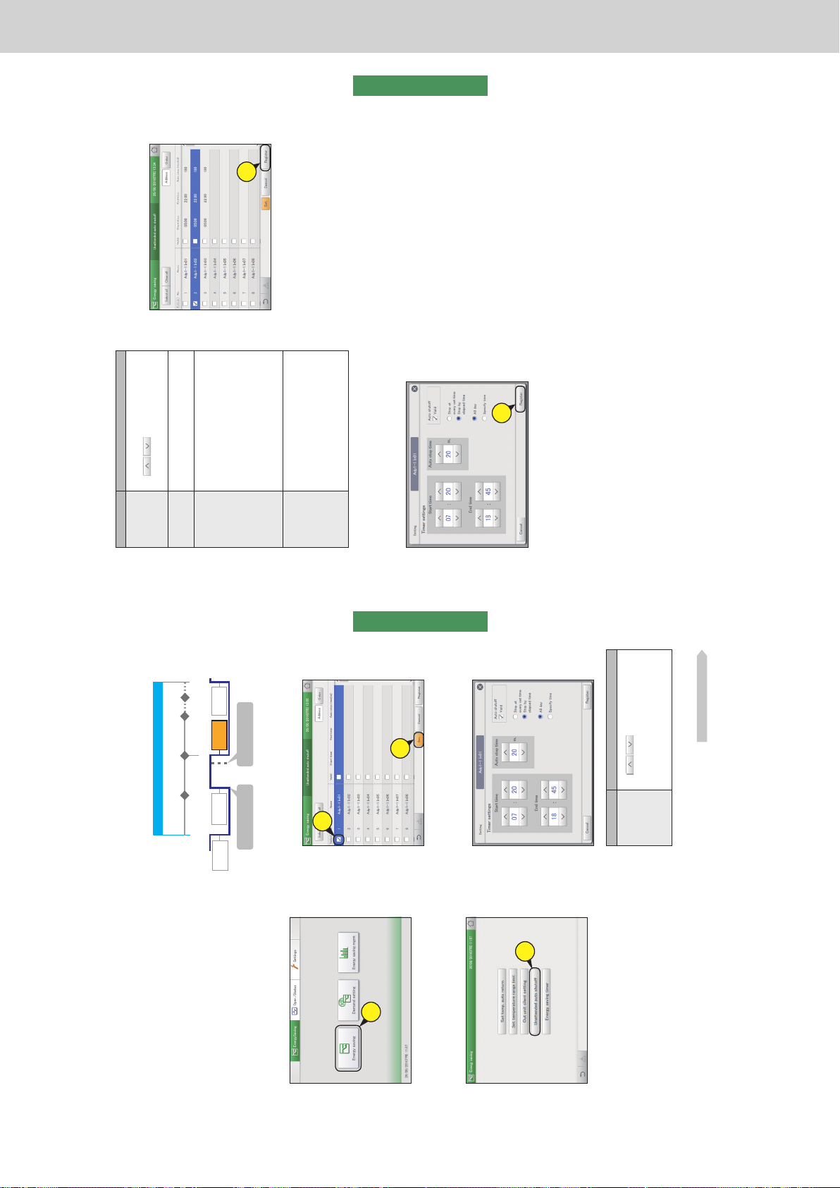
Operating Instructions Intelligent Controller
80
Settings for energy saving
Energy saving
Automatically stopping restarts [Unattended auto shutoff]
If air conditioning automatically stops at the time set on the timer, but then is started again, this setting
automatically stops the unit again repeatedly at set intervals, so it helps prevent people from forgetting to
turn the air conditioning off.
1
Touch [Energy saving] in “EnergySaving”.
1
2
Touch [Unattended auto shutoff].
z The “Unattended auto shutoff” screen is displayed.
2
3
Put a check mark in the “Select” column
(3-1), and touch [Set.] (3-2).
z The “Setting” dialogue is displayed.
3-
1
3-
2
4
Change the settings.
Item Explanation
Timer settings
(Start time, End
time)
Set the time slots to automatically stop.
Use
to set the time.
Note
y You can make the settings extend over
different dates.
For example: 22:00 to 08:00
Continued on next page
y When the settings are for closed between 21:00 and 09:00, and
the stop monitoring during closed hours is set to 60-minute
intervals
The “auto shutoff” feature works as many times as necessary
during the closed hours (21:00 to 9:00 the next morning in the
example).
Time set for unattended auto shutoff
Return to pick up
something
Leave without
turning off
ON
OFF
Detect Detect Detect
60 min.60 min.60 min.
AUTO
OFF
Closing time Opening time
9:0023:0022:0821:00
AUTO
OFF
Manual
ON
AUTO
ON
81
Settings for energy saving
Energy saving
7
Touch [Register].
z To cancel the settings, touch [Cancel].
7
Item Explanation
Auto stop time Set the time to automatically stop after operation
is started.
Use
to set the time.
You can set between 0 and 180 minutes
(5 minute intervals).
Auto shutoff The auto shutoff function is enabled for the
selected indoor unit if you put a check mark
here.
y Stop at every
set time
y Stop by
elapsed time
Select the stop conditions.
y “Stop at every set time”
Even after automatically stopping at
the “Start time”, the unit continues to
automatically stop repeatedly at the “Auto
stop time” interval.
y “Stop by elapsed time”
After automatically stopping at “Start time”
automatic stopping only happens after the
“Auto stop time” has elapsed if the indoor
unit is running.
y All day
y Specify time
Select the time conditions.
y “All day”
Automatic stopping at “Auto stop time”
continues repeatedly throughout the day.
(“Timer settings” is ignored)
y “Specify time”
Auto shutoff is repeated between the “Start
time” and the “End time”.
5
Touch [Register].
z The “Setting” dialogue closes.
z To cancel the settings, touch [Cancel].
5
6
Set other indoor units.
z Repeat steps 3 to 5.
Automatically stopping restarts [Unattended auto shutoff]
ー 86 ー
Page 89
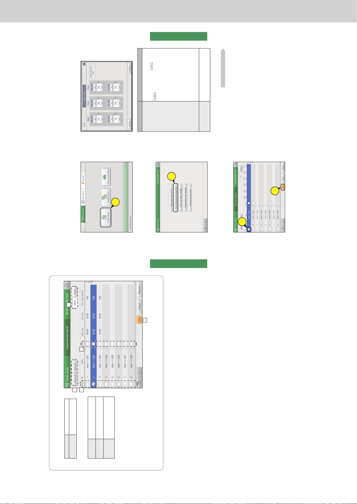
Operating Instructions Intelligent Controller
82
Settings for energy saving
Energy saving
The “Unattended auto shutoff” screen
A: [Select all]/[Clear all] buttons
[Select all] Select all indoor units.
[Clear all] Cancel selection of all
indoor units.
B: Change list order. The list order changes
each time you touch it.
Display The display follows the order set
in “I/D unit settings” (P.141).
O/D unit The display follows the address
order of the outdoor unit systems.
Address The display follows the address
order set in “I/D unit settings”
(P.141).
C: The indoor units with a check mark next to
them will be the subject of the changes to the
settings.
D: The unattended auto shutoff is enabled for
the selected indoor unit if you put a check
mark here. This is linked with the “Auto
shutoff” (“Setting” dialogue) (P.81) setting.
E: The “Setting” dialogue is displayed when you
touch this.
A
B
D
E
C
Automatically stopping restarts [Unattended auto shutoff]
83
Settings for energy saving
Energy saving
Restricting the range of set temperatures
[Set
temperature range limit]
Restrict the range of temperatures that can be set by setting upper and lower limits on temperatures.
4
Change the settings.
Item Explanation
High limit
Low limit
Set the upper temperature and lower
temperature for “Heat”, “Cool”, and “Auto”.
Set the temperature with
and
.
The setting ranges are as follows.
y In heating mode:
16 to 30 °C*
1
(1 °C intervals)
*1 The upper limit for gas heat pumps
is 26 °C.
y In cooling (drying) mode:
18 to 30 °C (1 °C intervals)
y In automatic mode:
17 to 27 °C (1 °C intervals)
Note
y The temperature range you can set
depends on the model.
Temp range limit The temperature range limit function is
enabled for the selected indoor unit if you
put a check mark here.
Continued on next page
1
Touch [Energy saving] in “EnergySaving”.
1
2
Touch [Set temperature range limit].
z The “Set temp. range limit” screen is displayed.
2
3
Put a check mark in the “Select” column
(3-1), and touch [Set.] (3-2).
z The “Setting” dialogue is displayed.
3-
1
3-
2
ー 87 ー
Page 90
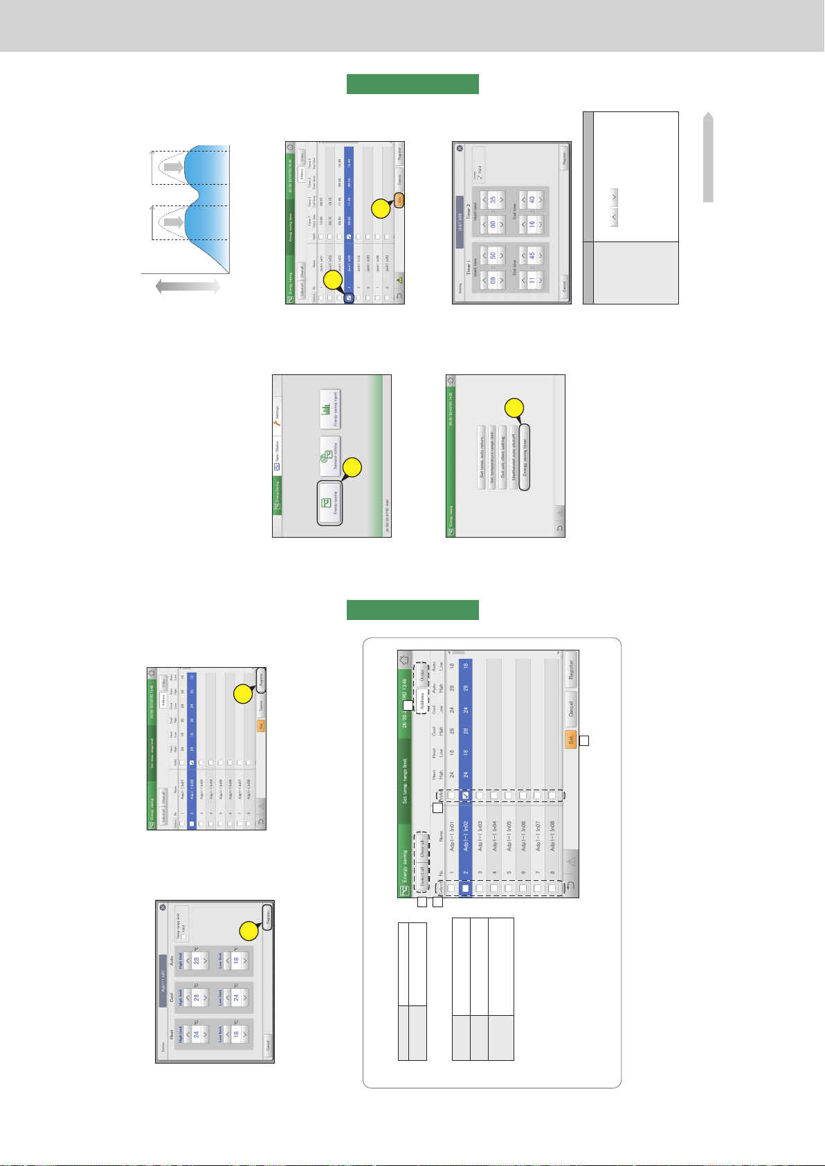
Operating Instructions Intelligent Controller
84
Settings for energy saving
Energy saving
5
Touch [Register].
z The “Setting” dialogue closes.
z To cancel the settings, touch [Cancel].
5
6
Set other indoor units.
z Repeat steps 3 to 5.
7
Touch [Register].
z To cancel the settings, touch [Cancel].
7
The “Set temp. range limit” screen
A: [Select all]/[Clear all] buttons
[Select all] Select all indoor units.
[Clear all] Cancel selection of all
indoor units.
B: Change list order. The list order changes
each time you touch it.
Display The display follows the order set
in “I/D unit settings” (P.141).
O/D unit The display follows the address
order of the outdoor unit systems.
Address The display follows the address
order set in “I/D unit settings”
(P.141).
C: The indoor units with a check mark next to
them will be the subject of the changes to the
settings.
D: The temperature range limit setting is enabled
for the selected indoor unit if you put a check
mark here. This is linked with the “Temp
range limit” (“Setting” dialogue) (P.83) setting.
E: The “Setting” dialogue is displayed when you
touch this.
A
B
D
E
C
Restricting the range of set temperatures [Set temperature range limit]
85
Settings for energy saving
Energy saving
Restricting operating capacity according to
the time slot
[Energy saving timer]/[Efcient operation setting*]
* When using gas heat pump air conditioners
You can specify time slots when you want
operation capacity reduced.
When set to the 10:00 to 12:00 and 13:00 to 15:00 time slots, the
consumption of electricity/gas is reduced during those time periods.
1
Touch [Energy saving] in “EnergySaving”.
1
2
Touch [Energy saving timer].
z The “Energy saving timer” screen is displayed.
2
3
Put a check mark in the “Select” column
(3-1), and touch [Set.] (3-2).
z The “Setting” dialogue is displayed.
3-
1
3-
2
4
Change the settings.
Item Explanation
Start time
End time
Set the start and end times for “Timer 1” and
“Timer 2”.
Use
to set the time.
The setting ranges are as follows.
y Hours: 00 to 23 (1 hour intervals)
y Minutes: 00 to 59 (1 minute intervals)
Note
y You can make the settings extend over
different dates.
For example: 22:00 to 08:00
Continued on next page
Energy saving
operation
10:00 12:00 15:0013:00
High
Electricity or gas consumed
Low
Energy saving
operation
ー 88 ー
Page 91
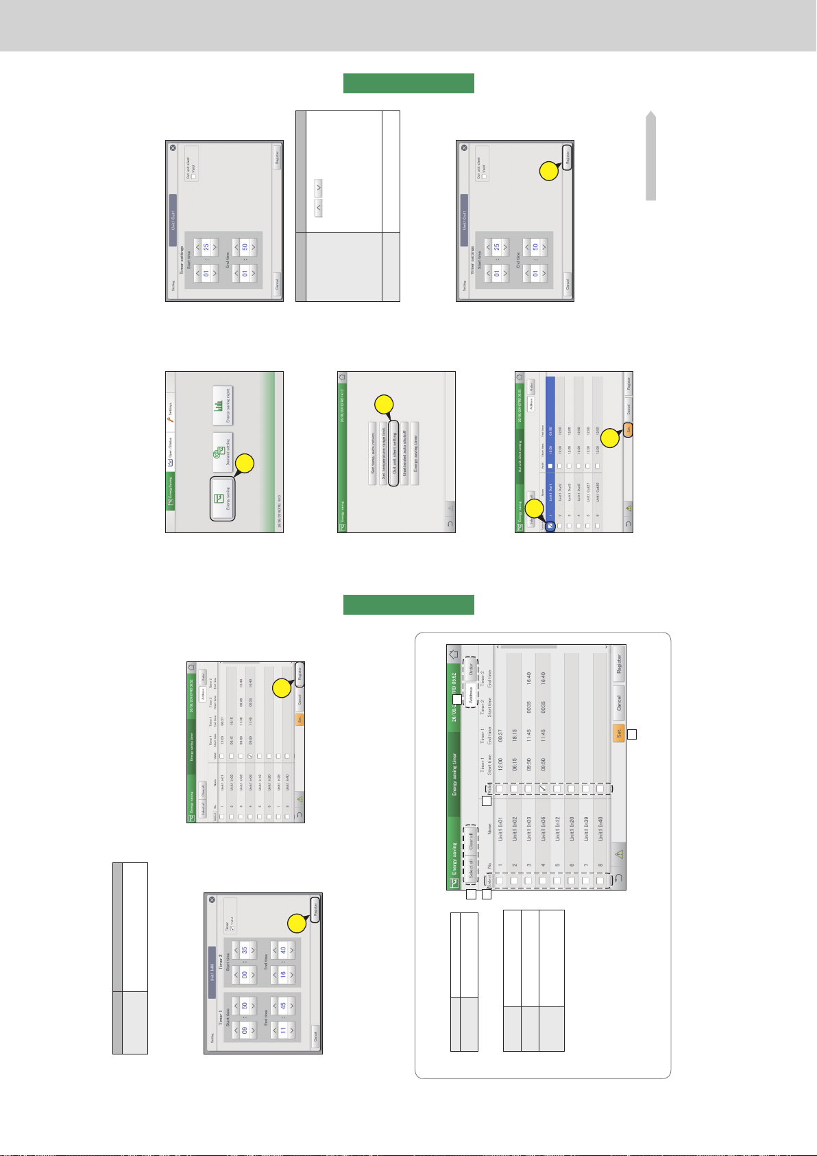
Operating Instructions Intelligent Controller
86
Settings for energy saving
Energy saving
6
Set other indoor units.
z Repeat steps 3 to 5.
7
Touch [Register].
z To cancel the settings, touch [Cancel].
7
Item Explanation
Timer The energy saving timer function is enabled
for the selected indoor unit if you put a check
mark here.
5
Touch [Register].
z The “Setting” dialogue closes.
z To cancel the settings, touch [Cancel].
5
The “Energy saving timer” screen
A: [Select all]/[Clear all] buttons
[Select all] Select all indoor units.
[Clear all] Cancel selection of all indoor
units.
B: Change list order. The list order changes
each time you touch it.
Display The display follows the order set
in “I/D unit settings” (P.141).
O/D unit The display follows the address
order of the outdoor unit systems.
Address The display follows the address
order set in “I/D unit settings”
(P.141).
C: The indoor units with a check mark next to
them will be the subject of the changes to the
settings.
D: The energy saving timer setting is enabled
for the selected indoor unit if you put a check
mark here. This is linked with the “Timer”
(“Setting” dialogue) setting.
E: The “Setting” dialogue is displayed when you
touch this.
A
B
D
E
C
Restricting operating capacity according to the time slot [Energy saving timer]/[Efcient operation setting]
Note
y The settings for efcient operation (when using gas heat pump air conditioners) are made in the same way as energy saving timer.
87
Settings for energy saving
Energy saving
Reducing the noise of outdoor units
[Out unit silent setting]
Set a time for the outdoor unit to operate more quietly at night compared to the day.
1
Touch [Energy saving] in “EnergySaving”.
1
2
Touch [Out unit silent setting].
z The “Out unit silent setting” screen is displayed.
2
3
Put a check mark in the “Select” column
(3-1), and touch [Set.] (3-2).
z The “Setting” dialogue is displayed.
3-
1
3-
2
4
Change the settings.
Item Explanation
Start time
End time
Set the start and end times.
Use
to set the time.
The setting ranges are as follows.
y Hours: 00 to 23 (1 hour intervals)
y Minutes: 00 to 59 (1 minute intervals)
Note
y You can make the settings extend over
different dates.
For example: 22:00 to 08:00
Out unit silent The silent operating mode is enabled if
you put a check mark here.
5
Touch [Register].
z The “Setting” dialogue closes.
z To cancel the settings, touch [Cancel].
5
6
Set other indoor units.
z Repeat steps 3 to 5.
Continued on next page
ー 89 ー
Page 92
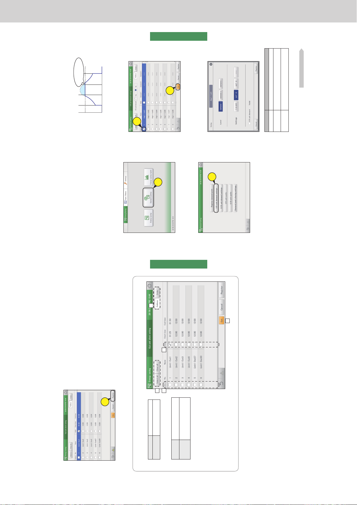
Operating Instructions Intelligent Controller
88
Settings for energy saving
Energy saving
7
Touch [Register].
z To cancel the settings, touch [Cancel].
7
The “Out unit silent setting” screen
A: [Select all]/[Clear all] buttons
[Select all] Select all outdoor units.
[Clear all] Cancel selection of all
outdoor units.
B: Change list order. The list order changes
each time you touch it.
Display The display follows the order set
in “I/D unit settings” (P.141).
Address The display follows the address
order set in “I/D unit settings”
(P.141).
C: The outdoor units with a check mark next to
them will be the subject of the changes to the
settings.
D: The out unit silent setting is enabled for the
selected out unit silentt if you put a check
mark here. This is linked with the “Out unit
silent” (“Setting” dialogue) (P.87) setting.
E: The “Setting” dialogue is displayed when you
touch this.
A
B
D
E
C
Reducing the noise of outdoor units [Out unit silent setting]
89
Settings for energy saving
Energy saving
Demand settings on the indoor unit
[I/D unit demand settings]
You can automatically control indoor units by setting indoor unit demand control levels to cut the
maximum demand for electricity or maximum gas consumption.
Set an operation when the setting levels for the demand point inputs come on.
Refer to P.104 for information on how to register demand point inputs.
3
Put a check mark in the “Select” column
(3-1), and touch [Set.] (3-2).
z The “Setting” dialogue is displayed.
3-
1
3-
2
4
Change the settings.
z Set the “Settings” for “Demand 1”, “Demand 2”, and
“Demand 3” in “Level”.
Item Explanation
Level Select a setting level.
Settings Select an operation.
No operation is caused if you select [----].
I/D unit demand
Valid
The demand setting is enabled for the selected
indoor unit if you put a check mark here.
Continued on next page
1
Touch [Demand setting] in
“EnergySaving”.
1
2
Touch [I/D unit demand settings].
z The “I/D unit demand settings” screen is displayed.
2
y When “±1°C” is set in the setting level “Demand 1” during
cooling
When the demand signal is received from the external equipment,
the demand 1 contact comes on and the set temperature is raised
by 1 °C.
8:00 12:00 20:0016:00
Electricity or gas consumed
Time
Reduced consumption
of electricity/gas!
Demand 1
(Set temperature
± 1 °C)
ー 90 ー
Page 93
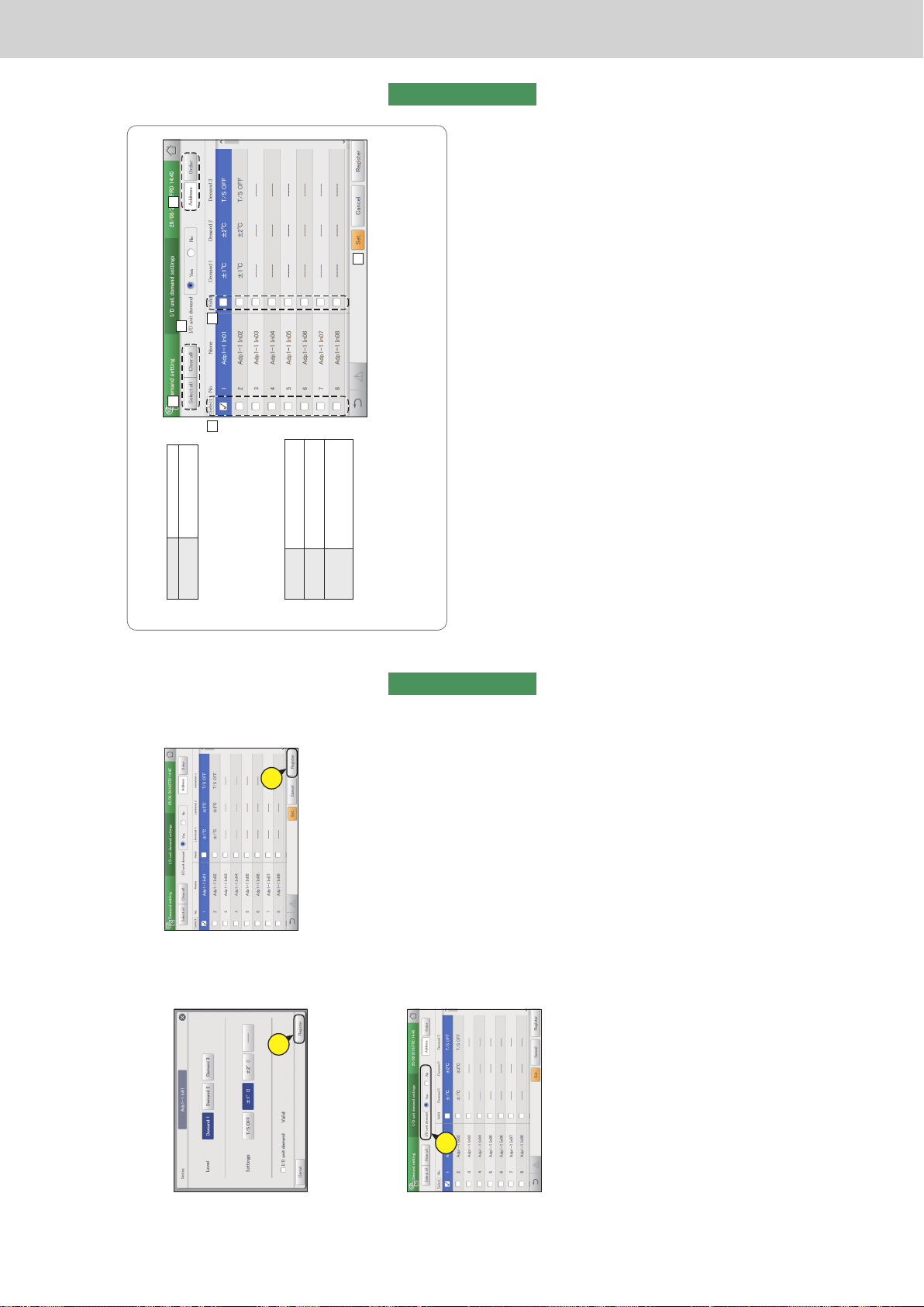
Operating Instructions Intelligent Controller
90
Settings for energy saving
Energy saving
5
Touch [Register].
z The “Setting” dialogue closes.
z To cancel the settings, touch [Cancel].
5
6
Set other indoor units.
z Repeat steps 3 to 5.
7
Select “Yes” for “I/D unit demand”.
7
8
Touch [Register].
z To cancel the settings, touch [Cancel].
8
Demand settings on the indoor unit [I/D unit demand settings]
91
Settings for energy saving
Energy saving
The “I/D unit demand settings” screen
A: [Select all]/[Clear all] buttons
[Select all] Select all indoor units.
[Clear all] Cancel selection of all
indoor units.
B: Set whether to enable indoor unit demand
control across the whole system or not.
Note
y If you select “Yes”, make sure that you set
“No” for outdoor unit demand settings.
C: Change list order. The list order changes
each time you touch it.
Display The display follows the order set
in “I/D unit settings” (P.141).
O/D unit The display follows the address
order of the outdoor unit systems.
Address The display follows the address
order set in “I/D unit settings”
(P.141).
D: The indoor units with a check mark next to
them will be the subject of the changes to
the settings.
E: The I/D unit demand setting is enabled for the selected indoor unit if you put a check mark here. This is linked with the “I/D unit
demand Valid” (“Setting” dialogue) (P.89) setting.
F: The “Setting” dialogue is displayed when you touch this.
A
C
F
B
D E
Demand settings on the indoor unit [I/D unit demand settings]
ー 91 ー
Page 94
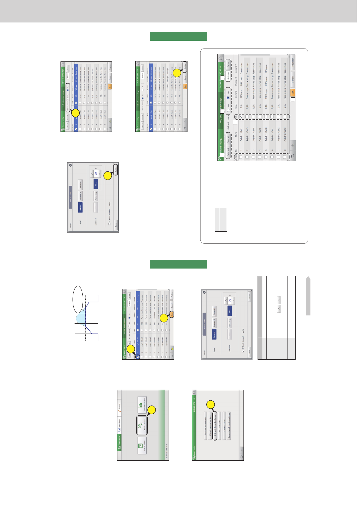
Operating Instructions Intelligent Controller
92
Settings for energy saving
Energy saving
Demand settings on the outdoor unit
[O/D unit demand settings]
You can automatically control outdoor units by setting outdoor unit demand control levels to cut the maximum
demand for electricity or maximum gas consumption.
Set an operation when the setting levels for the demand point inputs come on.
Refer to P.104 for information on how to register demand point inputs.
3
Put a check mark in the “Select” column
(3-1), and touch [Set.] (3-2).
z The “Setting” dialogue is displayed.
3-
1
3-
2
4
Change the settings.
z Set the “Demand” for “Demand 1”, “Demand 2”, and
“Demand 3” in “Level”.
Item Explanation
Level Select a setting level.
Demand Select an operation.
No operation is caused if you select [----].
When you have selected [Ope.] in “Demand”, set
the control rate with
. The values
shown are those values that can be set for the
outdoor unit selected.
O/D unit demand
Valid
The demand setting is enabled for the selected
outdoor unit if you put a check mark here.
Continued on next page
1
Touch [Demand setting] in
“EnergySaving”.
1
2
Touch [O/D unit demand settings].
z The “O/D unit demand settings” screen is displayed.
2
y When “Ope. 50%” is set in the setting level “Demand 1” during
warming
When the demand signal is received from the external equipment,
the demand 1 contact comes on and the operation of the outdoor
unit is restricted by 50%.
8:00 12:00 20:0016:00
Time
Reduced consumption
of electricity/gas!
Demand 1
(Operation 50%)
Electricity or gas consumed
93
Settings for energy saving
Energy saving
5
Touch [Register].
z The “Setting” dialogue closes.
z To cancel the settings, touch [Cancel].
5
6
Set other outdoor units.
z Repeat steps 3 to 5.
7
Select “Yes” for “O/D unit demand”.
7
8
Touch [Register].
z To cancel the settings, touch [Cancel].
8
The “O/D unit demand settings” screen
A: [Select all]/[Clear all] buttons
[Select all] Select all outdoor units.
[Clear all] Cancel selection of all
outdoor units.
B: Set whether to enable outdoor unit demand
control or not.
Note
y If you select “Yes”, make sure that you set
“No” for indoor unit demand settings.
C: This switches between “Display” and
“Address” each time you touch it.
D: The outdoor units with a check mark next to
them will be the subject of the changes to the
settings.
E: The O/D unit demand setting is enabled for
the selected outdoor unit if you put a check
mark here. This is linked with the “O/D unit
demand Valid” (“Setting” dialogue) (P.92)
setting.
F: The “Setting” dialogue is displayed when you
touch this.
A
CB
E
F
D
Demand settings on the outdoor unit [O/D unit demand settings]
ー 92 ー
Page 95
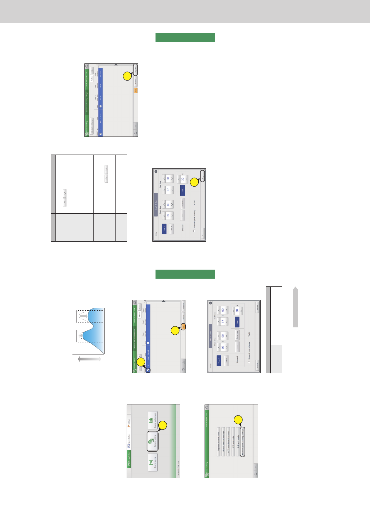
Operating Instructions Intelligent Controller
94
Settings for energy saving
Energy saving
Suppressing the consumption of electricity/
gas
[Demand/peak shaving settings]/[Peak cut settings*]
You can limit the electricity or gas consumed by outdoor units during the set time slot.
3
Put a check mark in the “Select” column
(3-1), and touch [Set.] (3-2).
z The “Setting” dialogue is displayed.
3-
1
3-
2
4
Change the settings.
Item Explanation
Timer 1
Timer 2
First select either “Timer 1” or “Timer 2”,
then set the “Start time”, “End time”, and
“Demand” for each of them.
Continued on next page
1
Touch [Demand setting] in
“EnergySaving”.
1
2
Touch [Demand/peak shaving settings].
z The “Demand/peak shaving settings” screen is displayed.
2
When set to the 10:00 to 12:00 and 13:00 to 15:00 time slots, the
consumption of electricity/gas by the outdoor units is reduced during
those time periods.
* When using gas heat pump air conditioners
Demand
operation
10:00 12:00 15:0013:00
High
Electricity or gas consumed
Low
Demand
operation
95
Settings for energy saving
Energy saving
6
Set other indoor units.
z Repeat steps 3 to 5.
7
Touch [Register].
z To cancel the settings, touch [Cancel].
7
Item Explanation
Start time
End time
Set the start and end times for “Timer 1” and
“Timer 2”.
Use
to set the time.
The setting ranges are as follows.
y Hours: 00 to 23 (1 hour intervals)
y Minutes: 00 to 59 (1 minute intervals)
Note
y You can make the settings extend over
different dates.
For example: 22:00 to 08:00.
Demand Select an operation.
No operation is caused if you select [----].
When you have selected [Ope.] in “Demand”,
set the control rate with
. The
values shown are those values that can be
set for the outdoor unit selected.
Demand/peak
shaving Valid
The outdoor unit time slot demand control
setting is enabled for the selected outdoor
unit if you put a check mark here.
5
Touch [Register].
z The “Setting” dialogue closes.
z To cancel the settings, touch [Cancel].
5
Suppressing the consumption of electricity/gas [Demand/peak shaving settings]/[Peak cut settings]
Note
y The settings for peak cut (when using gas heat pump air conditioners) are made in the same way as outdoor time slot demand settings.
ー 93 ー
Page 96
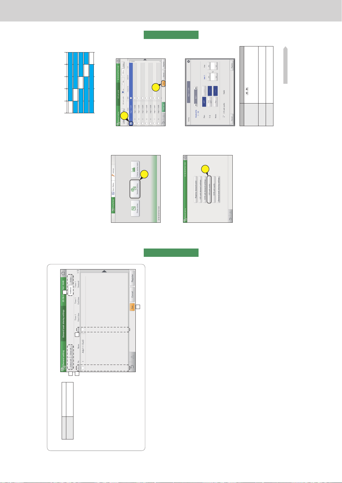
Operating Instructions Intelligent Controller
96
Settings for energy saving
Energy saving
The “Demand/peak shaving settings” screen
A: [Select all]/[Clear all] buttons
[Select all] Select all outdoor units.
[Clear all] Cancel selection of all
outdoor units.
B: This switches between “Display” and
“Address” each time you touch it.
C: The outdoor units with a check mark next to
them will be the subject of the changes to the
settings.
D: The outdoor time slot demand setting is
enabled for the selected outdoor unit if you
put a check mark here. This is linked with
the “Demand/peak shaving Valid” (“Setting”
dialogue) (P.95) setting.
E: The “Setting” dialogue is displayed when you
touch this.
A
B
D
E
C
Suppressing the consumption of electricity/gas [Demand/peak shaving settings]/[Peak cut settings]
97
Settings for energy saving
Energy saving
Control operation at regular intervals [I/D unit cyclic]
This type of control rotates through the set times slots at the specied intervals (3 minutes, 4 minutes,
5 minutes), evenly operating the indoor units in the control groups using the settings (OFF, thermostat,
mode, set temperature) and recovering.
3
Put a check mark in the “Select” column
(3-1), and touch [Set.] (3-2).
z The “Setting” dialogue is displayed.
3-
1
3-
2
4
Change the settings.
Item Explanation
Control Gr. 1-10
Press
to set the control group that
the indoor unit is to be allocated to. (Up to
10 groups)
Set from “Gr.1” to “Gr.10”.
Ope. Operation of the indoor units is stopped.
Set either [OFF] or [----]*.
T/S The thermostat is set to off forcibly.
Select between [T/S OFF] and [----]*.
Continued on next page
1
Touch [Demand setting] in
“EnergySaving”.
1
2
Touch [I/D unit cyclic].
z The “I/D unit cyclic” screen is displayed.
2
y When using cycling control at 5 minute intervals on the indoor
units in control groups 1 to 5
Control groups 1 to 3 are “T/S OFF” and control groups 4 and 5 are
“Fan”, and if the interval is “5 min.”, the cycling control happens at
5 minute intervals.
5 min. 5 min. 5 min. 5 min. 5 min.
Thermostat
forced OFF
Thermostat
forced OFF
Normal
operation
Normal operation
Normal operation
Normal operation
Normal operation
Normal operation
Normal
operation
Fan
Fan
Thermostat
forced OFF
Normal operation
Control group 1
Control group 2
Control group 3
Control group 4
Control group 5
ー 94 ー
Page 97
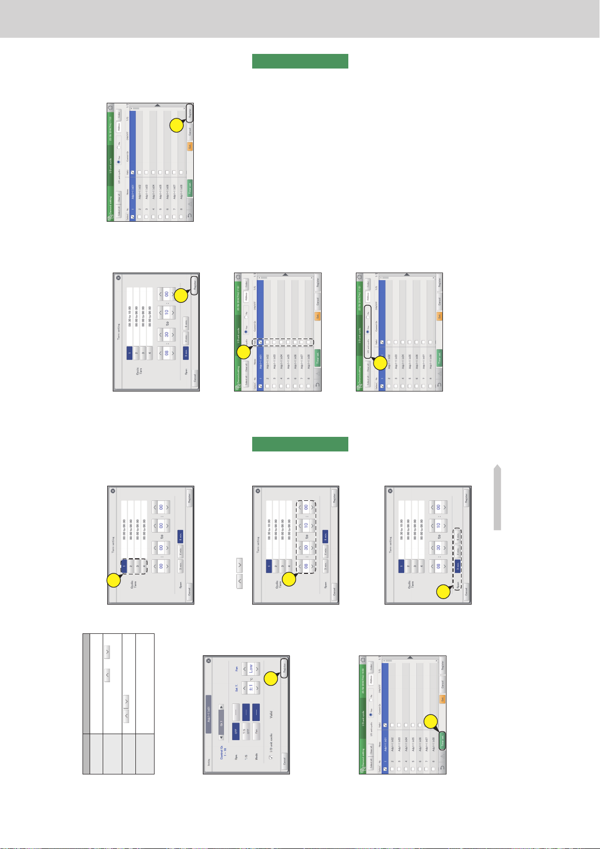
Operating Instructions Intelligent Controller
98
Settings for energy saving
Energy saving
Item Explanation
Mode Set the operating mode to fan.
Set either [Fan] or [----]*.
Set T.
Set the temperature with
and .
Set “±1” or “±2”, at 1 °C steps between 16 °C
and 28 °C*.
Fan
Use
to set the fan speed.
Set “Auto”, “High”, “Mid.”, or “Low”*.
I/D unit cyclic
Valid
The indoor unit cycling control function is
enabled for the selected indoor unit if you put a
check mark here.
* When left blank, that item does not cause any operation.
5
Touch [Register].
z The “Setting” dialogue closes.
z To cancel the settings, touch [Cancel].
5
6
Set other indoor units.
z Repeat steps 3 to 5.
7
Touch [Timer set.].
z The “Term setting” dialogue is displayed.
7
8
Touch the number.
z You can set 4 different time slots.
8
9
Set the times.
z The time on the left is the control start time. The time on
the right is the control end time.
z Use
to set the time. Hours can be set in the
range 0 to 23, and minutes may be either “00” or “30”.
9
10
Set the control interval.
z Select “3 min.”, “4 min.”, or “5 min.”.
z Repeat steps 7 to 9 to set for numbers [1] to [4].
10
Continued on next page
Control operation at regular intervals [I/D unit cyclic]
99
Settings for energy saving
Energy saving
11
Touch [Register].
z The “Term setting” dialogue closes.
z To cancel the settings, touch [Cancel].
11
12
Put a check mark in the “Valid” column.
12
13
Select “Yes” for “I/D unit cyclic”.
13
14
Touch [Register].
z To cancel the settings, touch [Cancel].
14
Note
y Up to 10 control groups can be created.
y Control groups that have not been set will not be the object of
cyclic control.
Control operation at regular intervals [I/D unit cyclic]
ー 95 ー
Page 98
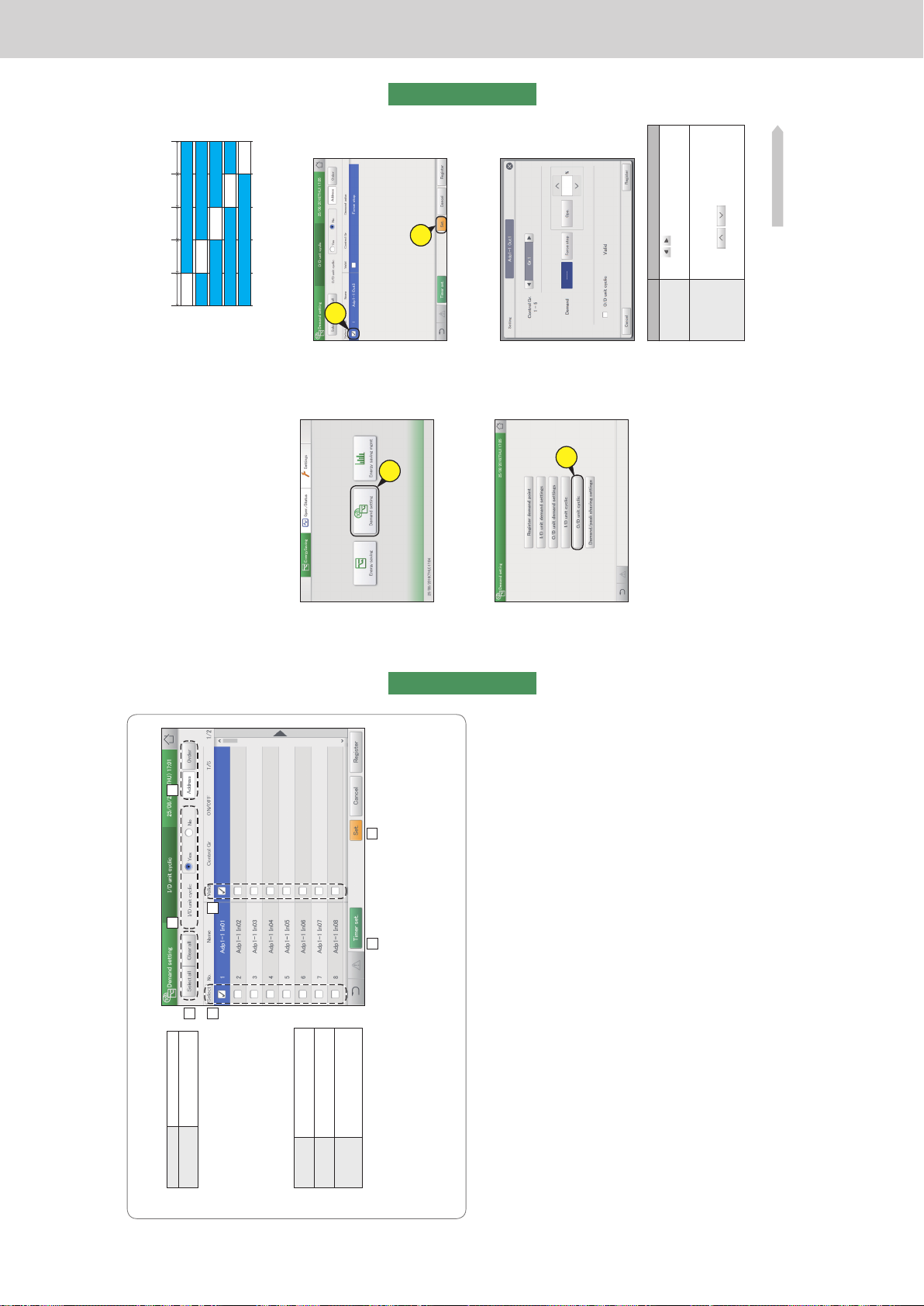
Operating Instructions Intelligent Controller
100
Settings for energy saving
Energy saving
The “I/D unit cyclic” screen
A: [Select all]/[Clear all] buttons
[Select all] Select all indoor units.
[Clear all] Cancel selection of all indoor
units.
B: Set whether to enable indoor unit cycling
control across the whole system or not.
Note
y If you select “Yes”, make sure that you
set “No” for outdoor unit cycling control
settings.
C: Change list order. The list order changes
each time you touch it.
Display The display follows the order set
in “I/D unit settings” (P.141).
O/D unit The display follows the address
order of the outdoor unit systems.
Address The display follows the address
order set in “I/D unit settings”
(P.141).
D: The indoor units with a check mark next to
them will be the subject of the changes to the
settings.
E: The I/D unit cyclic is enabled for the selected indoor unit if you put a check mark here. This is linked with the “I/D unit cyclic Valid”
(“Setting” dialogue) (P.98) setting.
F: The “Term setting” dialogue is displayed when you touch this.
G: The “Setting” dialogue is displayed when you touch this.
A
G
F
B C
D E
Control operation at regular intervals [I/D unit cyclic]
101
Settings for energy saving
Energy saving
This type of control rotates through at 10 minute intervals, evenly operating the outdoor units in the
control groups either operating (or stopping) and recovering.
3
Put a check mark in the “Select” column
(3-1), and touch [Set.] (3-2).
z The “Setting” dialogue is displayed.
3-
1
3-
2
4
Change the settings.
Item Explanation
Control Gr. 1-5
Press
to set the control group that the
indoor unit is to be allocated to.
Set from “Gr.1” to “Gr.5”.
Demand Select an operation.
No operation is caused if you select [----].
When you have selected [Ope.], set the control
rate with
. The values shown are
those values that can be set for the outdoor unit
selected.
Continued on next page
1
Touch [Demand setting] in
“EnergySaving”.
1
2
Touch [O/D unit cyclic].
z The “O/D unit cyclic” screen is displayed.
2
y When using cycling control at 10 minute intervals on the
outdoor units in control groups 1 to 5
Control groups 1 and 3 are “Force stop” and control groups 2, 4
and 5 are “50%” operation, and the cycling control happens at
10 minute intervals.
Control operation at regular intervals
[O/D unit cyclic]
10 min. 10 min. 10 min. 10 min. 10 min.
Forced stop
Forced stop
Normal
operation
Normal operation
Normal operation
Normal operation
Normal operation
Normal operation
Normal
operation
50% control
50% control
50% control
Normal operation
Control group 1
Control group 2
Control group 3
Control group 4
Control group 5
ー 96 ー
Page 99
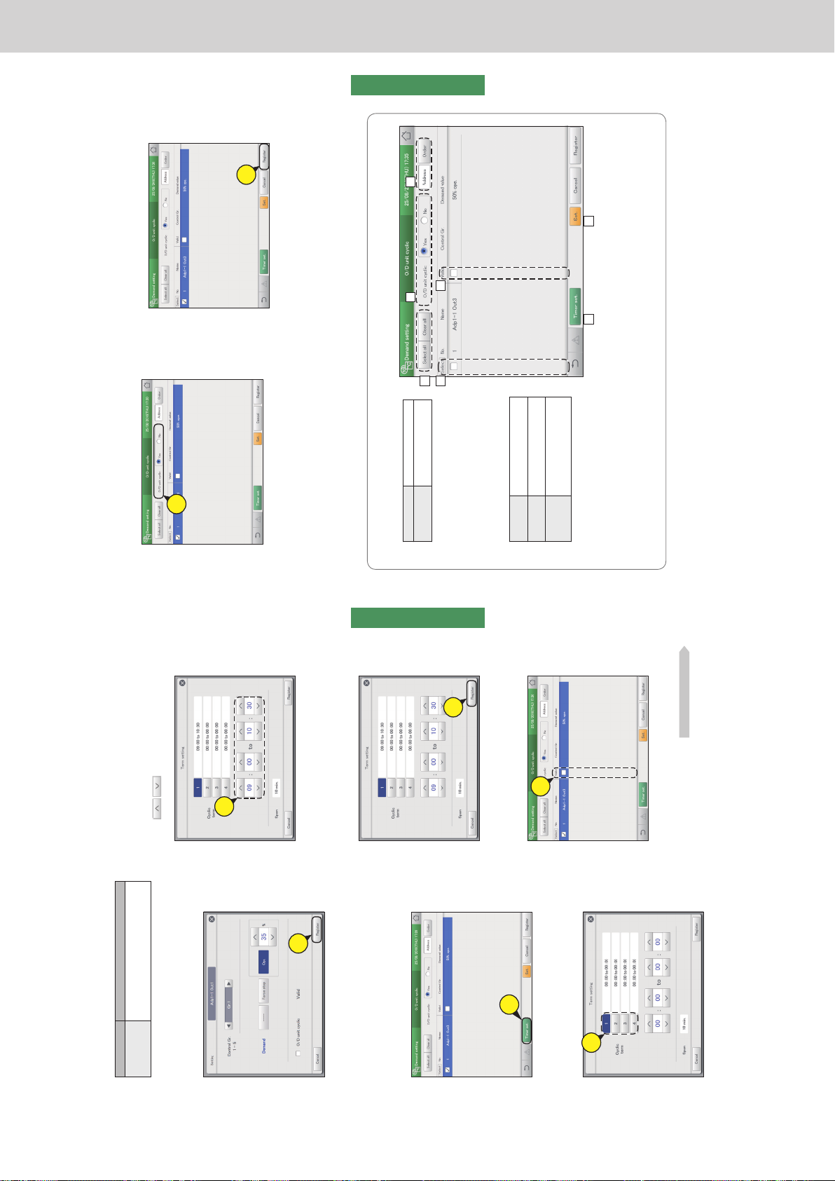
Operating Instructions Intelligent Controller
102
Settings for energy saving
Energy saving
9
Set the times.
z The time on the left is the control start time. The time on
the right is the control end time.
z Use
to set the time. Hours can be set in the
range 0 to 23, and minutes may be either “00” or “30”.
9
10
Touch [Register].
z The “Term setting” dialogue closes.
z To cancel the settings, touch [Cancel].
10
11
Put a check mark in the “Valid” column.
11
Continued on next page
Item Explanation
O/D unit cyclic
Valid
The O/D unit cyclic function is enabled for the
selected outdoor unit if you put a check mark
here.
5
Touch [Register].
z The “Setting” dialogue closes.
z To cancel the settings, touch [Cancel].
5
6
Set other indoor units.
z Repeat steps 3 to 5.
7
Touch [Timer set.].
z The “Term setting” dialogue is displayed.
7
8
Touch the number.
z You can set 4 different time slots.
8
Control operation at regular intervals [O/D unit cyclic]
103
Settings for energy saving
Energy saving
12
Select “Yes” for “O/D unit cyclic”.
12
13
Touch [Register].
z To cancel the settings, touch [Cancel].
13
Note
y Up to 5 control groups can be created.
y Control groups that have not been set will not be the object of
cyclic control.
The “O/D unit cyclic” screen
A: [Select all]/[Clear all] buttons
[Select all] Select all outdoor units.
[Clear all] Cancel selection of all
outdoor units.
B:
Set whether to enable outdoor unit cycling control
across the whole system or not.
Note
y If you select “Yes”, make sure that you set
“No” for indoor unit cycling control settings.
C: Change list order. The list order changes each
time you touch it.
Display The display follows the order set
in “I/D unit settings” (P.141).
O/D unit The display follows the address
order of the outdoor unit systems.
Address The display follows the address
order set in “I/D unit settings”
(P.141).
D: The outdoor units with a check mark next to
them will be the subject of the changes to the
settings.
E: The O/D unit cyclic is enabled for the selected outdoor unit if you put a check mark here. This is linked with the “O/D unit cyclic
Valid” (“Setting” dialogue) (P.102) setting.
F: The “Term setting” dialogue is displayed when you touch this.
G: The “Setting” dialogue is displayed when you touch this.
A
CB
E
GF
D
Control operation at regular intervals [O/D unit cyclic]
ー 97 ー
Page 100
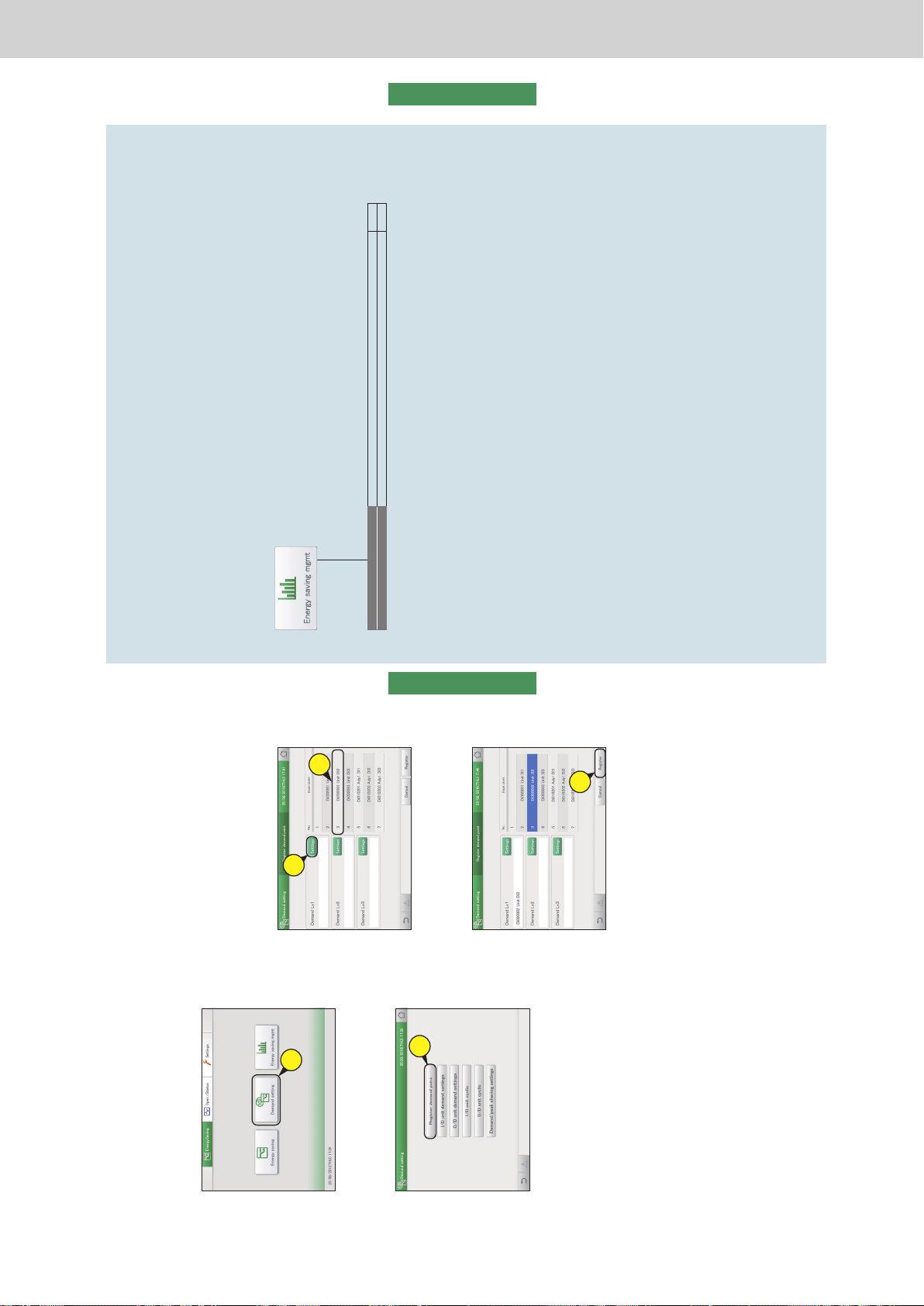
Operating Instructions Intelligent Controller
104
Settings for energy saving
Energy saving
Registering demand point input
[Register demand point]
Register the Di terminal of the main unit or the communication adaptor that inputs the demand point when
an external equipment is connected.
3
Select the communication adaptor from
the list at right (3-1) and touch [Settings]
(3-2).
z Set the demand points (“Demand 1”, “Demand 2”, and
“Demand 3”).
z You can change the name of the adaptor displayed
for the demand points. Touch the text box and change
with the touchscreen keyboard. (Enter a name up to
16 alphanumeric characters)
3-
1
3-
2
4
Touch [Register].
z To cancel the settings, touch [Cancel].
4
1
Touch [Demand setting] in
“EnergySaving”.
1
2
Touch [Register demand point].
z The “Register demand point” screen is displayed.
2
105
Displaying data in graphs
Energy saving
Displaying data in graphs
This chapter explains how to display graphs.
This unit is equipped with the functionality to collect the data accumulated in the devices and to turn this into
graphs.
Making the data visible makes it possible to objectively manage energy saving.
Screen menu Overview Page
Bar chart
Quantities of energy usage (electricity, gas), etc., are shown in bar charts. 109
Line graph
Temperature changes, etc., are shown in line graphs. 113
ー 98 ー
 Loading...