

Panasonic Cwxc103vu Owner's Manual
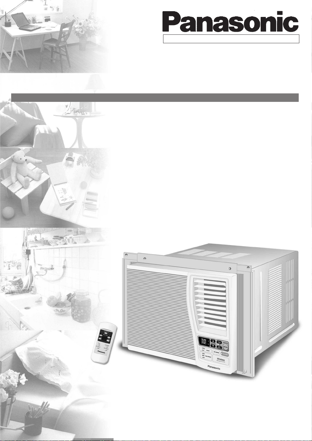
ROOM AIR CONDITIONER
OPERATING INSTRUCTIONS
MODEL: CW-XC103VU
CW-XC123VU
ENGLISH
Please read these operating instructions thoroughly before using
your air conditioner and keep them for future reference.
For assistance, please call: 1-800-211-PANA (7262) or send e-mail to
consumerproducts@panasonic.com
or refer to
www.panasonic.com
F563446

1
SAFETY PRECAUTIONS
Please observe these following safety precautions when using
your air conditioner.
• Failure or negligence in observing these safety precautions
could cause fire, electrical shock or personal injury.
This symbol (with a white background)
denotes an action that is PROHIBITED.
These symbols (with a blue background) denote
actions that are COMPULSORY.
INSTALLATION PRECAUTIONS
• Due to the weight of this product, we recommend that
you have a helper to assist in the installation. To avoid
injury, use the proper method of lifting. Avoid any sharp
edges.
• Make sure the window frame to be used can
properly support this product.
• This product must be installed in accordance with all local
codes and ordinances.
• Do not install the unit in places where inflammable gas,
fumes or soot may be generated.
OPERATION PRECAUTIONS
• Operate your air conditioner from a stable 115 volt AC
supply.
• Plug into a separate 15 amp grounded outlet only.
• Use of extension cords
Avoid using extension cords. If there are no alternatives,
ensure that the cord is a UL listed 3-wire grounding type,
rated 125 volts with a minimum current-carrying rating of
15 amps, number 14 or heavier wire.
• Use a 15 amp time delay fuse or a circuit breaker .
• Do not switch off by unplugging the power plug while it is
operating. Press the OFF/ON pad to “OFF” before
unplugging.
OPERATION PRECAUTIONS
WARNING
• Do not modify the length of the power cord or use an extension cord.
• Do not touch or operate with wet hands. Do not modify or damage
the cord.
• Do not turn on the unit by inserting the power plug. Do not switch off
the unit by pulling out the power plug.
• Avoid an extended period of direct airflow.
• Do not insert sticks, fingers or other objects into the unit.
• Do not try to repair the unit yourself.
• Plug in properly before operating and use a specified power cord.
• If abnormal conditions (burnt smell, etc) occur, switch off and remove
the power plug.
CAUTION
• Do not use the unit for other purposes, than its intended use.
• Do not remove the power plug by pulling the cord.
• Do not block the air intake and outlet vanes.
• Do not splash or direct water at the unit
• Do not expose the unit to direct sunlight during operation.
• Do not operate the unit without the air filter installed or when the front
intake grille has been removed.
• Do not place any objects on the unit.
• Do not operate any combustion equipment near the unit’s airflow area.
• Switch off the breaker and remove the power plug from the socket if
the unit will not be operated for a long period.
• Pay attention to any damages on the unit caused by extensive usage.
• Ventilate the room occasionally where the unit is installed.
• Remove the power plug when cleaning the unit.
This sign warns of risk of death or serious injury.
This sign warns of injury or damage to property.
POWER SUPPLY
Time Delay Fuse : 15 Amps
Rated Voltage : 115V
• Socket Type
• Line Cord Plug
2
INSTALLATION BOX CONTENTS
Sealer 50 g
(1.8 oz) (Putty)
Type A
screws
Type C screws
Type A screw
Left side
expandable panel
Top sealing
ribbon
Top
angle
Type B screws
ACCESSORIES
AIR CONDITIONER INSTALLATION
NOTE
Check that none of the accessories are missing.
Window sash
foam seal
Type A screws
(6 pcs)
(XTN5D25A)
(5 pcs)
(CWH4580211)
(6 pcs)
(XTT4D10C)
Window sash
sealing ribbon
SCREW FURNISHED
Side
sealing
ribbon
Type A
screw
Type A Type B Type C
(Qty 6) (Qty 5) (Qty 6)
SUGGESTED TOOL LIST
Type C screws
Right side
expandable
panel
SELECT THE BEST LOCATION
(Single or Double
Window
hung window)
Front grille
SIDE VIEW
Wood Machine Tapping
Screw Screw Screw
Medium sized
screwdriver (#2
Phillips)
Tape Measure
Pencil
Level
Knife or
Scissor
19–3/
inches
16
12 inches
More than
4 inches
WINDOW REQUIREMENTS
O
FF/O
N
O
P
E
R
A
T
IO
N
TEMP/TIMER
C
O
O
L
F
A
N
H
IG
H
M
E
D
L
O
W
M
O
D
E
F
A
N
S
P
E
E
D
SET
T
IM
E
R
SET/
CANCEL
A
IR
S
W
IN
G
E
C
O
N
O
M
Y
hr
°F
Wireless
R
e
m
o
te
C
o
n
tro
l
O
F
F
/O
N
OPERATION
T
E
M
P
/T
IM
E
R
C
O
O
L
F
A
N
H
IG
H
M
E
D
L
O
W
M
O
D
E
F
A
N
S
P
E
E
D
S
E
T
TIMER
S
E
T/
C
A
N
C
E
L
A
IR
S
W
IN
G
E
C
O
N
O
M
Y
hr
°F
Wireless
R
em
ote C
ontrol
OFF/ON
O
P
E
R
A
T
IO
N
TEMP/TIMER
CO
O
L
FAN
HIG
H
M
ED
LOW
M
O
DE
FAN SPEED
SET
T
I
M
E
R
S
E
T
/
C
A
N
C
E
L
AIR SW
ING
E
C
O
N
O
M
Y
h
r
°
F
W
ireless
R
e
m
o
te
C
o
n
tro
l
OFF/ON
O
P
E
R
A
TIO
N
TEMP/TIMER
COOL
FAN
HIGH
MED
LOW
MODE
FAN SPEED
SET
T
IM
E
R
SET/
CANCEL
AIR SWING
E
C
O
N
O
M
Y
h
r
°
F
W
ire
le
ss
R
em
ote C
ontrol
• Hot sun rays hitting the outside surface
of the cabinet will create considerable
heat load. If the outside of the cabinet is
exposed to direct sunlight, consider
building an awning to shade the cabinet
while providing ample area for the heated
air to be exhausted from the condenser
(both sides) and the top.
(min)
/16”
15
15-
22
to 42-
1
/
8
”
This unit is designed for installation in
standard double hung windows.
NOTE
The unit may also be installed “through the wall”. You should,
however, observe standard carpentry practices and frame the
opening without violating local ordinances.
INSTALLATION PROCEDURES
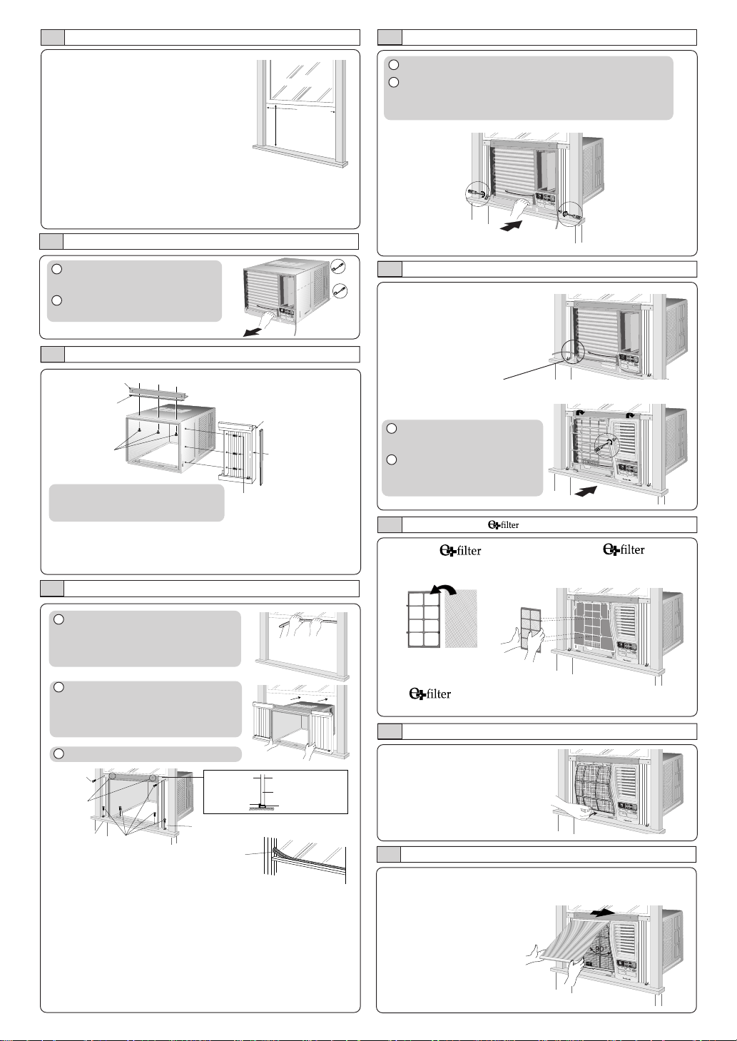
CHASSIS INSTALLATION INTO THE CABINET
1 Slide the chassis into the cabinet.
2 Reinstall the cabinet screws.
Secure the cabinet to chassis by using screws (from
rear cabinet).
°F
T
IM
E
O
R
P
E
R
A
T
IO
TEMP/TIMER
N
hr
SET
S
O
E
F
T
/
F
/O
N
C
A
N
C
E
L
C
O
O
L
F
A
M
N
O
D
E
A
IR
S
W
IN
G
H
IG
E
C
H
O
N
O
M
Y
M
E
D
F
A
N
S
P
E
E
D
L
O
W
Wireless
R
e
m
o
te
C
o
n
tro
l
1 Remove the rear cabinet
screws and save for later use.
2 Slide the chassis out from the
cabinet.
°F
TIMER
O
P
E
R
A
T
IO
T
N
E
M
P
/T
IM
E
R
hr
S
E
T
S
O
E
F
T
/
F
/
O
N
C
A
N
C
E
L
C
O
O
L
F
A
M
N
O
D
E
A
I
R
S
W
I
N
G
H
I
E
G
C
H
O
N
O
M
Y
M
E
D
F
A
N
S
P
E
E
D
L
O
W
Wireless
Remote Control
HOW TO ASSEMBLE THE EXPANDABLE PANELS
Top sealing
ribbon (To be
attached to the
top angle)
Type B screws
NOTE
This procedure applies to left and right
of assembling expandable panel.
Top angle
Expandable panel
Side sealing ribbon
(To be attached to
the expandable
panel)
Type C screws
• Attach the top angle to the cabinet using screw type B (3 pcs).
• Insert expandable panels to cabinet sides as shown.
• Secure the first fold of expansion panel to cabinet using screw
type C (3 each).
CABINET INSTALLATION
1 Cut the “Sealing Ribbon” to the
proper length, and attach it along
the bottom edge of the bottom
window sash.
Window sash
sealing ribbon
INSTALLATION OF THE FRONT GRILLE
Depending upon the location
of the AC outlet, route the AC
cord to either the left or right
side while installing the front
grille.
This figure shows the AC cord
routed to the left side.
1 Place the front grille on the
cabinet first.
2 Secure the front grille to the
main chassis using screw
provided.
INSERT THE
Attach the (part no.
CZ-SF6P) to the frame.
Slot in the and the
frame (part no. CZ-SFW6P) to
the front grille.
°F
T
IM
E
O
R
P
E
R
A
T
IO
TEMP/TIMER
N
hr
SET
SET/
O
F
F
/O
N
CANCEL
C
O
O
L
F
A
M
N
O
D
E
A
IR
S
W
IN
G
H
IG
E
C
H
O
N
O
M
Y
M
E
D
F
A
N
S
P
E
E
D
L
O
W
Wireless
R
e
m
o
t
e
C
o
n
t
r
o
l
2 To prevent condensation water
from dripping inside, the cabinet
should be installed level or very
slightly tilted to the outside.
3 Secure the cabinet using screws.
Type A
screw
Type B
screws
Inside of
sash
Top angle
Outside of sash
Window sash
Sealing ribbon
Expandable panel
Window sill
Type A
screws
Window sash
foam seal
• Expand the expandable panel fully into the grooves of the
window frame, secure the expandable panel, left, right and
top mounting frames to the bottom of the window sash
using 4 screws type A and 2 screws type B.
• Secure the cabinet using wood screws type A.
• Cut the window sash foam seal to the proper size and
seal the opening between the top of the inside window
sash and the outside window sash.
Note :If a gap exists between the unit and window sash, you may
use “Sealer” supplied with the installation kit for a better seal.
The and the frame can be obtained separately
from your nearest servicenter.
INSERT THE AIR FILTER
Attach the air filter to the intake grille
PLACE FRONT INTAKE GRILLE OVER THE FRONT GRILLE
Slide the front intake grille slightly to the right to reattach the
tabs and then push it down to close tight.
Lift up about 90°.
 Loading...