

Panasonic CW-XC100VK, CW-XC120VK Installation And Operating Instructions Manual
INSTALLATION AND
OPERATING INSTRUCTIONS
MODEL: CW-XC100VK
CW-XC120VK
ROOM AIR CONDITIONER
F563665
Please read these operating instructions thoroughly before using
your air conditioner and keep them for future reference.
ENGLISH
Please observe these following safety precautions when using
your air conditioner.
• Failure or negligence in observing these safety precautions
could cause fire, electrical shock or personal injury.
This symbol (with a white background)
denotes an action that is PROHIBITED.
1
SAFETY PRECAUTIONS
These symbols (with a blue background) denote
actions that are COMPULSORY.
INSTALLATION PRECAUTIONS
OPERATION PRECAUTIONS
This sign warns of risk of death or serious injury.
• Do not modify the length of the power cord or use an extension cord.
• Do not touch or operate with wet hands. Do not modify or damage
the cord.
• Do not turn on the unit by inserting the power plug. Do not switch off
the unit by pulling out the power plug.
• Avoid an extended period of direct airflow.
• Do not insert sticks, fingers or other objects into the unit.
• Do not try to repair the unit yourself.
• Plug in properly before operating and use a specified power cord.
• If abnormal conditions (burnt smell, etc) occur, switch off and remove
the power plug.
WARNING
• Do not use the unit for other purposes, than its intended use.
• Do not remove the power plug by pulling the cord.
• Do not block the air intake and outlet vanes.
• Do not splash or direct water at the unit
• Do not expose the unit to direct sunlight during operation.
• Do not operate the unit without the air filter installed or when the front
intake grille has been removed.
• Do not place any objects on the unit.
• Do not operate any combustion equipment near the unit’s airflow area.
• Switch off the breaker and remove the power plug from the socket if
the unit will not be operated for a long period.
• Pay attention to any damages on the unit caused by extensive usage.
• Ventilate the room occasionally where the unit is installed.
• Remove the power plug when cleaning the unit.
CAUTION
2
AIR CONDITIONER INSTALLATION
• Due to the weight of this product, we recommend that
you have a helper to assist in the installation. To avoid
injury, use the proper method of lifting. Avoid any sharp
edges.
• Make sure the window frame to be used can
properly support this product.
• This product must be installed in accordance with all local
codes and ordinances.
• Do not install the unit in places where inflammable gas,
fumes or soot may be generated.
POWER SUPPLY
• Operate your air conditioner from a stable 115 volt AC
supply.
• Plug into a separate 15 amp grounded outlet only.
• Use of extension cords
Avoid using extension cords. If there are no alternatives,
ensure that the cord is CSA approved 3-wire grounding
type, rated 125 volts with a minimum current-carrying
rating of 15 amps, number 14 or heavier wire.
• Use a 15 amp time delay fuse or a circuit breaker .
• Do not switch off by unplugging the power plug while it is
operating. Press the OFF/ON pad to “OFF” before
unplugging.
This sign warns of injury or damage to property.
OPERATION PRECAUTIONS
Time Delay Fuse : 15 Amps
Rated Voltage : 115V
• Socket Type
• Line Cord Plug
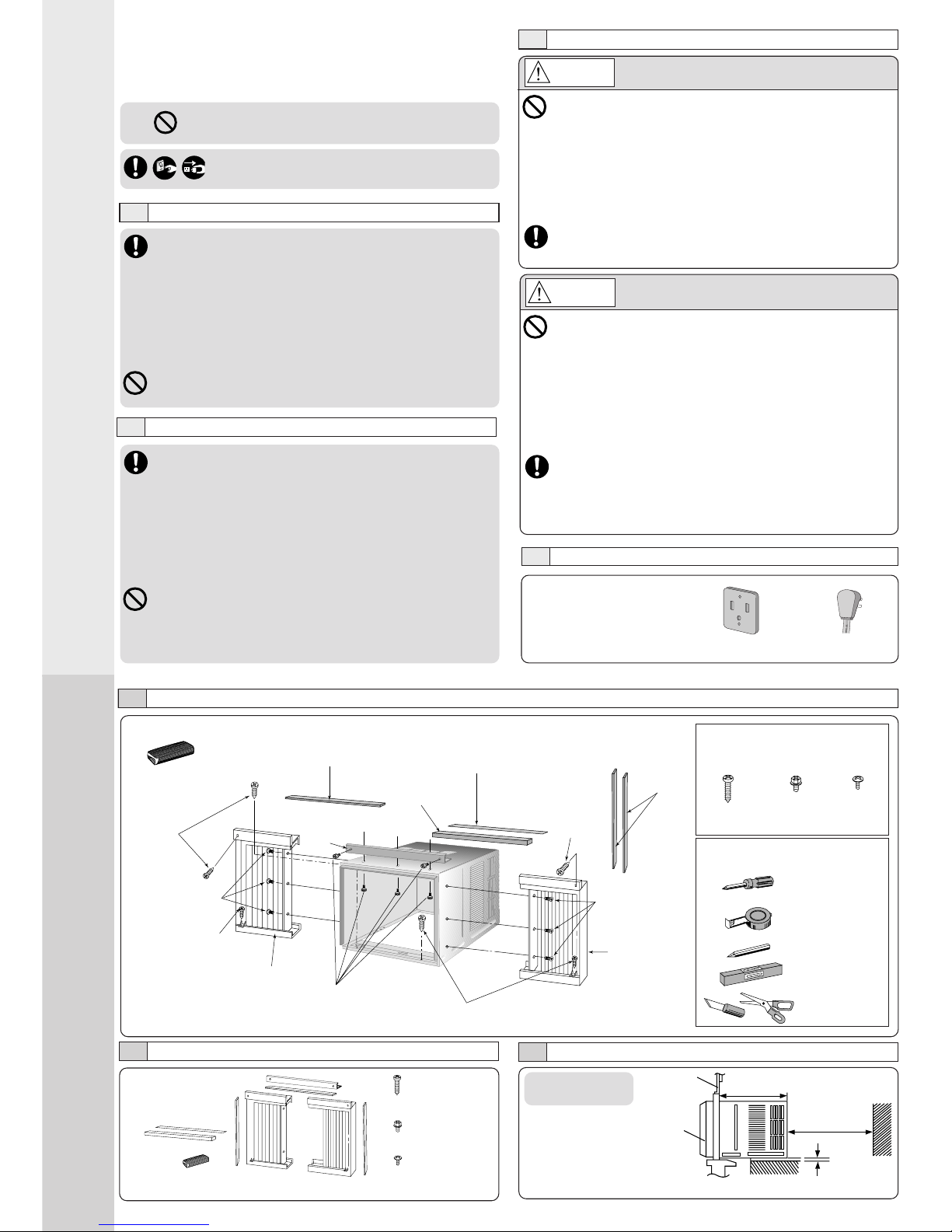
INSTALLATION BOX CONTENTS
Sealer 50 g
(1.8 oz) (Putty)
Type A
screw
Window sash
sealing ribbon
Type C screws
Type B screws
Left side
expandible panel
Type A
screws
Type C screws
Top
angle
Window sash
foam seal
Right side
expandible
panel
Type A Type B Type C
(Qty 6) (Qty 5) (Qty 6)
SCREW FURNISHED
Wood Machine Tapping
Screw Screw Screw
SUGGESTED TOOL LIST
Medium sized
screwdriver (#2
Phillips)
Tape Measure
Pencil
Level
Knife or
Scissor
ACCESSORIES
NOTE
Check that none of the accessories are missing.
(6 pcs)
(XTN5D25A)
(5 pcs)
(CWH4580211)
(6 pcs)
(XTT4D8C)
SELECT THE BEST LOCATION
(Single or Double
hung window)
19–3/
16
inches
SIDE VIEW
Front grille
Window
12 inches
More than
4 inches
Type A screws
Type A screw
Top sealing
ribbon
Side
sealing
ribbon
WINDOW REQUIREMENTS
• Hot sun rays hitting the outside surface
of the cabinet will create considerable
heat load. If the outside of the cabinet is
exposed to direct sunlight, consider
building an awning to shade the cabinet
while providing ample area for the heated
air to be exhausted from the condenser
(both sides) and the top.
This unit is designed for installation in
standard double hung windows.
NOTE
The unit may also be installed “through the wall”. You should,
however, observe standard carpentry practices and frame the
opening without violating local ordinances.
INSTALLATION PROCEDURES
HOW TO ASSEMBLE THE EXPANDABLE PANELS
Top angle
Type B screws
Type C screws
• Attach the top angle to the cabinet using screw type B (3 pcs).
• Insert expandible panels to cabinet sides as shown.
• Secure the first fold of expansion panel to cabinet using screw
type C (3 each).
Expandible panel
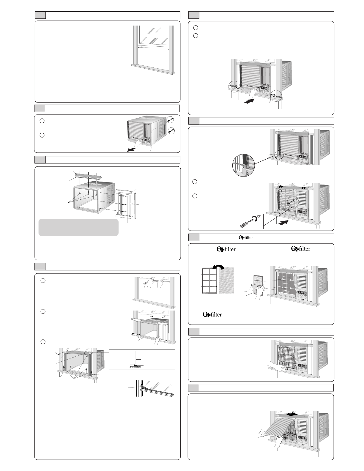
CHASSIS INSTALLATION INTO THE CABINET
1
Remove the rear cabinet
screws and save for later use.
2
Slide the chassis out from the
cabinet.
CABINET INSTALLATION
1
Cut the “Sealing Ribbon” to the
proper length, and attach it along
the bottom edge of the bottom
window sash.
2
To prevent condensation water
from dripping inside, the cabinet
should be installed level or very
slightly tilted to the outside.
3
Secure the cabinet using screws.
• Expand the expandable panel fully into the grooves of the
window frame, secure the expandable panel, left, right and
top mounting frames to the bottom of the window sash
using 6 screws type A and 2 screws type B.
• Secure the cabinet using wood screws type A.
• Cut the window sash foam seal to the proper size and
seal the opening between the top of the inside window
sash and the outside window sash.
Note :If a gap exists between the unit and window sash, you may
use “Sealer” supplied with the installation kit for a better seal.
Window sash
sealing ribbon
1
Slide the chassis into the cabinet.
2
Reinstall the cabinet screws.
Secure the cabinet to chassis by using screws (from
rear cabinet).
INSTALLATION OF THE FRONT GRILLE
Depending upon the location
of the AC outlet, route the AC
cord to either the left or right
side while installing the front
grille.
This figure shows the AC cord
routed to the left side.
INSERT THE
Attach the (part no.
CZ-SF6P) to the frame.
Slot in the and the
frame (part no. CZ-SFW6P) to
the front grille.
The and the frame can be obtained separately
from your nearest servicentre.
INSERT THE AIR FILTER
Attach the air filter to the intake grille
PLACE FRONT INTAKE GRILLE OVER THE FRONT GRILLE
Slide the front intake grille slightly to the right to reattach the
tabs and then push it down to close tight.
NOTE
This procedure applies to left and right
of assembling expandable panel.
O
F
F
/
O
N
OPERATION
T
E
M
P
/
T
I
M
E
R
C
O
O
L
F
A
N
H
I
G
H
L
O
W
M
O
D
E
F
A
N
S
P
E
E
D
S
E
T
T
I
M
E
R
SET/
CANCEL
A
I
R
S
W
I
N
G
J
E
T
M
O
D
E
h
r
¡
C
W
i
r
e
l
e
s
s
R
em
ote
C
ontrol
O
F
F
/
O
N
O
P
E
R
A
T
I
O
N
T
E
M
P
/
T
I
M
E
R
C
O
O
L
F
A
N
H
I
G
H
L
O
W
M
O
D
E
F
A
N
S
P
E
E
D
S
E
T
T
I
M
E
R
S
E
T
/
C
A
N
C
E
L
A
I
R
S
W
I
N
G
J
E
T
M
O
D
E
h
r
¡
C
W
ir
e
le
s
s
R
e
m
o
t
e
C
o
n
t
r
o
l
OFF/O
N
O
P
E
R
A
T
I
O
N
T
E
M
P
/
T
I
M
E
R
C
O
O
L
F
A
N
H
I
G
H
L
O
W
M
O
D
E
F
A
N
S
P
E
E
D
S
E
T
T
I
M
E
R
S
E
T
/
C
A
N
C
E
L
A
I
R
S
W
I
N
G
J
E
T
M
O
D
E
h
r
¡
C
W
i
r
e
l
e
s
s
R
e
m
o
t
e
C
o
n
t
r
o
l
O
F
F
/
O
N
O
P
E
R
A
T
I
O
N
T
E
M
P
/
T
I
M
E
R
C
O
O
L
F
A
N
H
I
G
H
L
O
W
M
O
D
E
F
A
N
S
P
E
E
D
S
E
T
T
I
M
E
R
S
E
T
/
C
A
N
C
E
L
A
I
R
S
W
I
N
G
J
E
T
M
O
D
E
h
r
¡
C
W
i
r
e
l
e
s
s
R
e
m
o
t
e
C
o
n
t
r
o
l
O
F
F
/
O
N
O
P
E
R
A
T
I
O
N
T
E
M
P
/
T
I
M
E
R
C
O
O
L
F
A
N
H
I
G
H
L
O
W
M
O
D
E
F
A
N
S
P
E
E
D
S
E
T
T
I
M
E
R
S
E
T
/
C
A
N
C
E
L
A
I
R
S
W
I
N
G
J
E
T
M
O
D
E
h
r
¡
C
W
i
r
e
l
e
s
s
R
e
m
o
t
e
C
o
n
t
r
o
l
O
F
F
/
O
N
O
P
E
R
A
T
I
O
N
T
E
M
P
/
T
IM
E
R
C
O
O
L
F
A
N
H
I
G
H
L
O
W
M
O
D
E
F
A
N
S
P
E
E
D
S
E
T
TI
M
E
R
S
E
T
/
C
A
N
C
E
L
A
I
R
S
W
I
N
G
J
E
T
MO
D
E
h
r
¡
C
W
i
r
e
l
e
s
s
R
e
m
o
t
e
C
o
n
t
r
o
l
1
Place the front grille on the
cabinet first.
2
Secure the front grille to the
main chassis using screw
provided.
15-
15
/
16
”
(min)
2
2
to
4
2
-
1
/
8
”
Top sealing
ribbon (To be
attached to the
top angle)
Side sealing ribbon
(To be attached to
the expandible
panel)
Window sash
foam seal
Type A
screw
Type B
screws
Window sill
Type A
screws
Expandible panel
Outside of sash
Window sash
Sealing ribbon
Top angle
Inside of
sash
O
F
F
/O
N
O
P
ER
AT
ION
T
E
M
P
/
T
I
M
E
R
C
O
O
L
F
A
N
H
I
G
H
L
O
W
M
O
D
E
F
A
N
S
P
E
E
D
S
E
T
T
I
M
E
R
SE
T
/
C
AN
CE
L
A
I
R
S
W
I
N
G
J
E
T
M
O
D
E
h
r
¡
C
W
i
r
e
l
e
s
s
R
e
m
o
t
e
C
o
n
t
r
o
l
Clockwise.
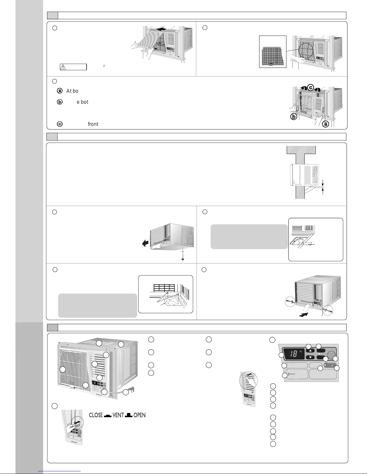
1 Air inlet louvre 4 Air filter (behind the
front intake grille)
2 Cabinet 5 Front intake
grille
3 Power cord 6 Front grille
7 Vertical airflow direction vane
(Airflow direction adjustment updown).
The vertical airflow direction vane
is controlled by rotating the
horizontal vane forward or backward.
2
AIR CONDITIONER INSTALLATION
3
P ART IDENTIFICA TION
REMOVAL OF FRONT GRILLE
1
Remove the front intake grille.
Pull up the front intake grille
about 90° and slide it slightly
to the left to unhook the tabs.
2
Remove the air filter.
Tilt up and pull out
the air filter by the
holder.
3
Remove the front grille.
aa
aa
a
At bottom right side of the front grille, press inward on cabinet near the power cord, and pull
the grille outward to the right until right tab releases.
bb
bb
b
At the bottom left side, push inward on cabinet and pull the grille outward to the left to release
the left tab.
Do not pull the bottom edge toward you more than 3 inches to prevent the two top tabs from
damage.
cc
cc
c
Slide the front grille upwards to free the two top tabs from slots at the top of the cabinet.
HOW TO ATTACH THE DRAIN PAN (OPTIONAL)
Maximum
13/32”
Condensed water
This air conditioner employs a “Slinger-Up System” which is designed to splash the condensed
water on the condenser coil for maximum cooling efficiency, thus producing a splashing sound.
If the splashing sound annoys you, you can provide an outside drainage by using the following
procedure which may, however, cause a small loss of performance.
Note: The cabinet should be installed tilted slightly lower to the rear for necessary condensate
drainage. (Max. 13/32”)
Condensed water drainage
1
Remove the rubber plug and slide the chassis out from
the cabinet.
Remove the
rubber plug
O
F
F
/
O
N
O
PE
RATIO
N
T
E
M
P
/
T
I
M
E
R
C
O
O
L
F
A
N
H
I
G
H
L
O
W
M
O
D
E
F
A
N
S
P
E
E
D
S
E
T
T
I
M
E
R
S
E
T
/
C
A
N
C
E
L
A
I
R
S
W
I
N
G
J
E
T
M
O
D
E
h
r
¡
C
W
ire
le
s
s
R
e
m
o
t
e
C
o
n
t
r
o
l
2
Install the optional drain pan (part no. CWH40175).
Screws
INTERNAL VIEW
Drain pan (optional)
Install the drain pan at the right
corner of the cabinet using 2
screws (part no. CWG86C733).
3
Connect a drain hose (optional).
Fit the drain hose to the drain pan.
Underside view with drain
pan and hose in place.
Drain hose
(not included)
4
Slide the chassis back into the
cabinet.
Reinstall the cabinet screws.
Secure the cabinet to chassis by
using screws.
Note
The drain pan (part no.
CWH40175) can be obtained
from nearest servicentre.
MAIN UNIT
O
F
F
/
O
N
O
P
E
R
A
T
I
O
N
T
E
M
P
/
T
I
M
E
R
C
O
O
L
F
A
N
H
I
G
H
L
O
W
M
O
D
E
F
A
N
S
P
E
E
D
S
E
T
T
I
M
E
R
S
E
T
/
C
A
N
C
E
L
A
I
R
S
W
I
N
G
J
E
T
M
O
D
E
h
r
¡
C
W
i
r
e
l
e
s
s
R
e
m
o
t
e
C
o
n
t
r
o
l
9 Touch control panel
OFF/ON
OPERATION
TEMP/TIMER
COOL
FAN
HIGH
LOW
MODE
FAN SPEED
SET
TIMER
SET/
CANCEL
AIR SWING
JET
MODE
hr
Wireless
Remote Control
a Display Panel
b MODE selection pad
c FAN SPEED selection pad
d TEMPERATURE/TIMER
setting pad
e TIMER pad
f Timer SET/CANCEL pad
g OPERATION OFF/ON pad
h AIR SWING pad
i JET MODE pad
a
b
c
d
e
f
g
h
i
Note
Drain hose or tubing can be
purchased locally to satisfy your
particular needs.
TYPES OF SIGNAL SOUND
One long “Beep” and one short “Beep”. (Sound from the main unit.)
EXTERNAL VIEW
1
2
3
4
5
6
8
7
9
O
F
F
/
O
N
O
P
E
R
A
T
IO
N
T
E
M
P
/
T
I
M
E
R
C
O
O
L
F
A
N
H
I
G
H
L
O
W
M
O
D
E
F
A
N
S
P
E
E
D
S
E
T
T
I
M
E
R
SE
T
/
C
A
NC
E
L
A
I
R
S
W
I
N
G
J
E
T
M
O
D
E
h
r
¡
C
W
i
r
e
l
e
s
s
R
e
m
o
t
e
C
o
n
t
r
o
l
Air filter
O
F
F
/
O
N
O
P
E
R
A
T
I
O
N
T
E
M
P
/
T
I
M
E
R
C
O
O
L
F
A
N
H
I
G
H
L
O
W
M
O
D
E
F
A
N
S
P
E
E
D
S
E
T
T
I
M
E
R
S
E
T
/
C
A
N
C
E
L
A
I
R
S
W
I
N
G
J
E
T
M
O
D
E
h
r
¡
C
W
i
r
e
l
e
s
s
R
e
m
o
t
e
C
o
n
t
r
o
l
aa
aa
a
bb
bb
b
cc
cc
c
O
F
F
/
O
N
OPERA
TI
ON
T
E
M
P
/
T
I
M
E
R
C
O
O
L
F
A
N
H
I
G
H
L
O
W
M
O
D
E
F
A
N
S
P
E
E
D
S
E
T
T
I
M
E
R
S
E
T
/
C
A
N
C
E
L
A
I
R
S
W
I
N
G
J
E
T
M
O
D
E
h
r
¡
C
W
i
r
e
l
e
s
s
R
e
m
o
t
e
C
o
n
t
r
o
l
O
F
F
/
O
N
O
P
E
R
A
T
I
O
N
T
E
M
P
/
T
I
M
E
R
C
O
O
L
F
A
N
H
I
G
H
L
O
W
M
O
D
E
F
A
N
S
P
E
E
D
S
E
T
T
I
M
E
R
S
E
T
/
C
A
N
C
E
L
A
I
R
S
W
I
N
G
J
E
T
M
O
D
E
h
r
¡
C
W
i
r
e
l
e
s
s
R
e
m
o
t
e
C
o
n
t
r
o
l
8 Ventilation lever
The ventilation lever must be in the CLOSE position in order to
maintain the best cooling conditions. When fresh air is necessary
in the room, set the ventilation lever to the OPEN position. The
damper is opened and room air is drawn out.
O
F
F
/O
N
O
P
E
R
A
T
I
O
N
T
E
M
P
/
T
I
M
E
R
C
O
O
L
F
A
N
H
I
G
H
L
O
W
M
O
D
E
F
A
N
S
P
E
E
D
S
E
T
T
I
M
E
R
S
E
T
/
C
A
N
C
E
L
A
I
R
S
W
I
N
G
J
E
T
M
O
D
E
hr
¡F
W
i
r
e
l
e
s
s
R
e
m
o
t
e
C
o
n
t
r
o
l
Do not raise the front intake grille any higher than
90° to the unit or damage to the tabs may occur.
CAUTION

3
PART
IDENTIFICATION
4
PREP ARATION BEFORE
OPERATING
ACCESSORIES
• Remote control • Two R03 dry-cell batteries
•
and frame
Be sure to observe the following:
• Aim remote control at control
panel on air conditioner when
operating.
• Do not drop or throw the remote
control.
• Do not place the remote control
in a location that is exposed to
direct sunlight or next to a heating
unit or other heat sources.
O
F
F
/
O
N
O
P
E
R
A
T
I
O
N
T
E
M
P
/
T
I
M
E
R
C
O
O
L
F
A
N
H
I
G
H
L
O
W
M
O
D
E
F
A
N
S
P
E
E
D
S
E
T
T
I
M
E
R
S
E
T
/
C
A
N
C
E
L
A
I
R
S
W
I
N
G
J
E
T
M
O
D
E
h
r
¡
C
Wirele
ss
R
e
m
o
t
e
C
o
n
t
r
o
l
• Maximum distance : 10 m
Panasonic
AIR SWING
MODE
OPERATION
FAN SPEED
JET MODE
SET/
CANCEL
TEMP/TIMER
TIMER
1 Signal Transmitter
2 OPERATION button
3 TEMPERATURE/TIMER setting button
4 TIMER button
5 TIMER SET/CANCEL button
6 MODE selection button
7 JET MODE Button
8 AIR SWING button
9 Fan Speed Selection Button
REMOTE CONTROL
1
2
3
5
7
9
6
8
4
NOTES
• If the unit is not going to be used for an extended period of time, remove the
power plug. Otherwise, approximately 2.5W of electricity will be used even if the
unit has been turned off using the remote control.
• If operation is stopped, and to be restarted immediately, the unit will resume
operation only after 3 minutes.
ABOUT THE BATTERIES
WARNING
3
1
Open the cover.
HOW TO INSERT BATTERIES
Insert the two batteries.
2
Do not use rechargeable (Ni-Cd) batteries
because such batteries differ from the standard
dry cell batteries in shape, dimension and
performance.
Close the cover.
CAUTION
Ensure that the power
plug is securely inserted.
A loose plug may cause a
fire or an electric shock.
• The batteries can be used for approximately one year.
• Be sure to replace the batteries with two new identical
batteries.
• Remove the batteries if the air conditioner will not be used
for an extended period of time.
5
AIR CONDITIONER OPERATION
OPERATING THE UNIT
Start operation by pressing
OPERATION.
The operation will turn on and the
display panel will light up.
To stop the operation, press the
OPERATION again.
The unit will stop operating and the
display panel light will turn off.
SELECTING OPERATION MODE
Press MODE to select the desired
operation .
The indicator will light up and a “beep”
sound will indicate changing setting.
COOL mode
To set room temperature to your
preference of cooling comfort.
FAN mode
T o provide air circulation without cooling
the room.
During Fan operation, temperature
setting cannot be selected.
SETTING DISPLAY TEMPERATURE
Press TEMP/TIMER ▲ or ▼ to set the
display temperature.
The temperature can be set between
16°C and 30°C.
Recommended temperature:
26°C ~ 28°C.
Display will
change
according to
the setting.
NOTES
• The latest temperature setting will be memorized and will
appear on the display the next time it’s turned on.
• The display temperature selection is for display purpose only
and does not indicate actual room setting temperatures. Your
room temperature may not necessarily match the displayed
temperature.
SELECTING FAN SPEED
Press FAN SPEED to choose the
speed level of the fan.
The indicator will light up and the “beep”
sound will indicate changing setting.
Vertical
louvres
ADJUSTING HORIZONTAL AIR FLOW DIRECTION
Press to select AIR SWING.
The air circulation will automatically move the
horizontal louvres left and right for better air
distribution around the room.
NOTE
Using your hands to adjust the direction may cause
the louvres to malfunction. If this happens, stop
operation immediately and restart.
NOTE
Vertical adjustment of the airflow direction
is done manually.
NOTE
• The latest fan speed setting will be memorized and the indicator
will light up the next time the unit is turned on.
OFF/ON
OPERATION
OPERATION
TEMP/TIMER
COOL
FAN
MODE
TEMP/TIMER
hr
hr
°C
hr
°C
FAN SPEED
AIR SWING
MODE
HIGH
LOW
FAN SPEED
AIR SWING
COOL
FAN
HIGH
LOW
O
F
F
/
O
N
O
P
ER
AT
IO
N
T
E
M
P
/
T
I
M
E
R
C
O
O
L
F
A
N
H
I
G
H
L
O
W
M
O
D
E
F
A
N
S
P
E
E
D
S
E
T
T
I
M
E
R
S
E
T
/
C
A
N
C
E
L
A
I
R
S
W
I
N
G
J
E
T
M
O
D
E
hr
¡C
W
i
r
e
l
e
s
s
R
e
m
o
t
e
C
o
n
t
r
o
l
 Loading...