

Page 1
Order No: PHAAM1111121A1
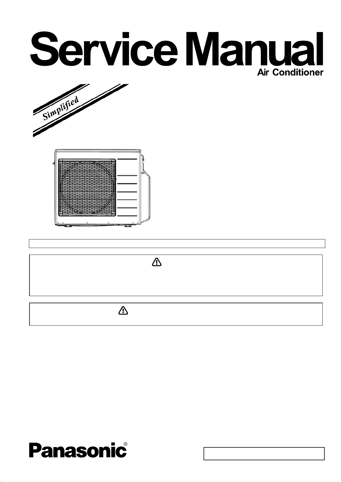
Outdoor Unit
CU-2S18NBU-1
Please file and use this manual together with the service manual for Model No. CS-S9NKUW-1, CS-S12NKUW-1 Order No. PHAAM1111084C1
WARNING
This service information is designed for experienced repair technicians only and is not designed for use by the general public.
It does not contain warnings or cautions to advise non-technical individuals of potential dangers in attempting to service a product.
Products powered by electricity should be serviced or repaired only by experienced professional technicians. Any attempt to
service or repair the product or products dealt with in this service information by anyone else could result in serious injury or death.
In order to avoid frostbite, be assured of no refrigerant leakage during the installation or repairing of refrigerantion circuit.
PRECAUTION OF LOW TEMPERATURE
TABLE OF CONTENTS
1. Safety Precautions.............................................3
2. Specification.......................................................5
3. Dimensions.........................................................7
4. Refrigeration Cycle Diagram.............................8
5. Block Diagram....................................................9
6. Wiring Connection Diagram............................10
7. Electronic Circuit Diagram..............................11
8. Printed Circuit Board.......................................12
8.1 Main Printed Circuit Board .........................12
8.2 Noise Filter Printed Circuit Board...............13
9. Installation Information ...................................14
9.1 Check Points ..............................................14
10. Installation Instruction.....................................15
10.1 SELECT THE BEST LOCATION ...............15
10.2 INSTALL THE OUTDOOR UNIT................17
10.3 CONNECT THE PIPING............................17
10.4 EVACUATION OF THE EQUIPMENT.......18
10.5 CONNECT THE CABLE TO THE
OUTDOOR UNIT........................................18
10.6 HEAT INSULATION ...................................19
11. Operation Control.............................................20
© Panasonic HA Air-Conditioning (M) Sdn. Bhd. 2011.
Unauthorized copying and distribution is a violation of law.
Page 2

12.12
Valve close detection control......................23
12.13 Compressor discharge high pressure
protection control ........................................23
13. Servicing Mode.................................................24
13.1 Pump Down Operation ...............................24
13.2 Test Operation............................................24
13.3 Wiring Error Check .....................................24
13.4 Power Save Mode ......................................25
13.5 Mode priority function .................................25
14. Troubleshooting Guide....................................26
14.1 Self Diagnosis Function..............................26
15. Disassembly and Assembly Instructions ......28
15.1 Outdoor Unit Removal Procedure ..............28
16. Technical Data ..................................................31
16.1 Operation Characteristics...........................31
17. Exploded View and Replacement Parts List..41
2
Page 3
1. Safety Precautions
• Read the following “SAFETY PRECAUTIONS” carefully before perform any servicing.
• Electrical work must be installed or serviced by a licensed electrician. Be sure to use the correct rating of the power plug and
main circuit for the model installed.
• The caution items stated here must be followed because these important contents are related to safety. The meaning of each
indication used is as below. Incorrect installation or servicing due to ignoring of the instruction will cause harm or damage,
and the seriousness is classified by the following indications.
WARNING
CAUTION
• The items to be followed are classified by the symbols:
• Carry out test running to confirm that no abnormality occurs after the servicing. Then, explain to user the operation, care and
maintenance as stated in instructions. Please remind the customer to keep the operating instructions for future reference.
1. Do not modify the machine, part, material during repairing service.
2. If wiring unit is supplied as repairing part, do not repair or connect the wire even only partial wire break. Exchange the whole wiring unit.
This indication shows the possibility of causing death or serious injury.
This indication shows the possibility of causing injury or damage to properties.
This symbol denotes item that is PROHIBITED from doing.
WARNING
3. Do not wrench the fasten terminal. Pull it out or insert it straightly.
Engage authorized dealer or specialist for installation and servicing. If installation or servicing done by the user is defective, it will cause
4.
water leakage, electrical shock or fire.
5. Install according to this installation instructions strictly. If installation is defective, it will cause water leakage, electric shock or fire.
Use the attached accessories parts and specified parts for installation and servicing. Otherwise, it will cause the set to fall, water leakage,
6.
fire or electrical shock.
Install at a strong and firm location which is able to withstand the set’s weight. If the strength is not enough or installation is not properly
7.
done, the set will drop and cause injury.
For electrical work, follow the local national wiring standard, regulation and the installation instruction. An independent circuit and single
8.
outlet must be used. If electrical circuit capacity is not enough or defect found in electrical work, it will cause electrical shock or fire.
This equipment is strongly recommended to be installed with Earth Leakage Circuit Breaker (ELCB) or Residual Current Device (RCD).
9.
Otherwise, it may cause electrical shock and fire in case equipment breakdown or insulation breakdown.
Do not use joint cable for indoor / outdoor connection cable. Use specified indoor / outdoor connection cable, refer to Installation
10.
Instructions CONNECT THE CABLE TO THE INDOOR UNIT and connect tightly for indoor / outdoor connection. Clamp the cable so that
no external force will be acted on the terminal. If connection or fixing is not perfect, it will cause heat up or fire at the connection.
Wire routing must be properly arranged so that control board cover is fixed properly. If control board cover is not fixed perfectly, it will
11.
cause heat-up or fire at the connection point of terminal, fire or electrical shock.
When install or relocate air conditioner, do not let any substance other than the specified refrigerant, eg. air etc. mix into refrigerant cycle
12.
(piping). (Mixing of air etc. will cause abnormal high pressure in refrigeration cycle and result in explosion, injury etc.).
Do not install outdoor unit near handrail of veranda. When installing air-conditioner unit at veranda of high rise building, child may
13.
climb up to outdoor unit and cross over the handrail and causing accident.
This equipment must be properly earthed. Earth line must not be connected to gas pipe, water pipe, earth of lightning rod and
14.
telephone. Otherwise, it may cause electrical shock in case equipment breakdown or insulation breakdown.
15. Keep away from small children, the thin film may cling to nose and mouth and prevent breathing.
Do not use unspecified cord, modified cord, joint cord or extension cord for power supply cord. Do not share the single outlet with
16.
other electrical appliances. Poor contact, poor insulation or over current will cause electrical shock or fire.
Tighten the flare nut with torque wrench according to specified method. If the flare nut is over-tightened, after a long period, the
17.
flare may break and cause refrigerant gas leakage.
For R410A models, when connecting the piping, do not use any existing (R22) pipes and flare nuts. Using such same may cause
abnormally high pressure in the refrigeration cycle (piping), and possibly result in explosion and injury. Use only R410A materials.
18.
Thickness of copper pipes used with R410A must be more than 0.8mm (1/32”). Never use copper pipes thinner than 0.8mm
(1/32”).
It is desirable that the amount of residual oil is less than 40 mg/10m (0.0008 oz/ft).
During installation, install the refrigerant piping properly before run the compressor. (Operation of compressor without fixing refrigeration
19.
piping and valves at opened condition will cause suck-in of air, abnormal high pressure in refrigeration cycle and result in explosion, injury
etc.).
3
Page 4
WARNING
During pump down operation, stop the compressor before remove the refrigeration piping. (Removal of refrigeration piping while
20.
compressor is operating and valves are opened condition will cause suck-in of air, abnormal high pressure in refrigeration cycle and result
in explosion, injury etc.).
After completion of installation or service, confirm there is no leakage of refrigerant gas. It may generate toxic gas when the refrigerant
21.
contacts with fire.
22. Ventilate if there is refrigerant gas leakage during operation. It may cause toxic gas when the refrigerant contacts with fire.
23. Do not insert your fingers or other objects into the unit, high speed rotating fan may cause injury.
24. Must not use other parts except original parts describe in catalog and manual.
25. Using of refrigerant other than the specified type may cause product damage, burst and injury etc.
CAUTION
Do not install the unit at place where leakage of flammable gas may occur. In case gas leaks and accumulates at surrounding of
1.
the unit, it may cause fire.
Carry out drainage piping as mentioned in installation instructions. If drainage is not perfect, water may enter the room and damage the
2.
furniture.
Tighten the flare nut with torque wrench according to specified method. If the flare nut is over-tightened, after a long period, the flare may
3.
break and cause refrigerant gas leakage.
4. Do not touch outdoor unit air inlet and aluminium fin. It may cause injury.
5. Select an installation location which is easy for maintenance.
Pb free solder has a higher melting point than standard solder; typically the melting point is 50°F – 70°F (30°C – 40°C) higher. Please use
6.
a high temperature solder iron. In case of the soldering iron with temperature control, please set it to 700 ± 20°F (370 ± 10°C).
Pb free solder will tend to splash when heated too high (about 1100°F / 600°C).
Power supply connection to the air conditioner.
Power supply cord shall be UL listed or CSA approved 4 conductors with minimum AWG12 wires.
Power supply point should be in an easily accessible place for power disconnection in case of emergency.
7.
In some countries, permanent connection of this air conditioner to the power supply is prohibited.
Fix power supply connection to a circuit breaker for the permanent connection.
Use NRTL approved fuse or circuit breaker (rating refers to name plate) for the permanent connection.
Do not release refrigerant during piping work for installation, servicing, reinstallation and during repairing a refrigerant parts. Take
8.
care of the liquid refrigerant, it may cause frostbite.
9. Installation or servicing work: It may need two people to carry out the installation or servicing work.
10. Do not install this appliance in a laundry room or other location where water may drip from the ceiling, etc.
11. Do not sit or step on the unit, you may fall down accidentally.
12. Do not touch the sharp aluminum fin, sharp parts may cause injury.
4
Page 5
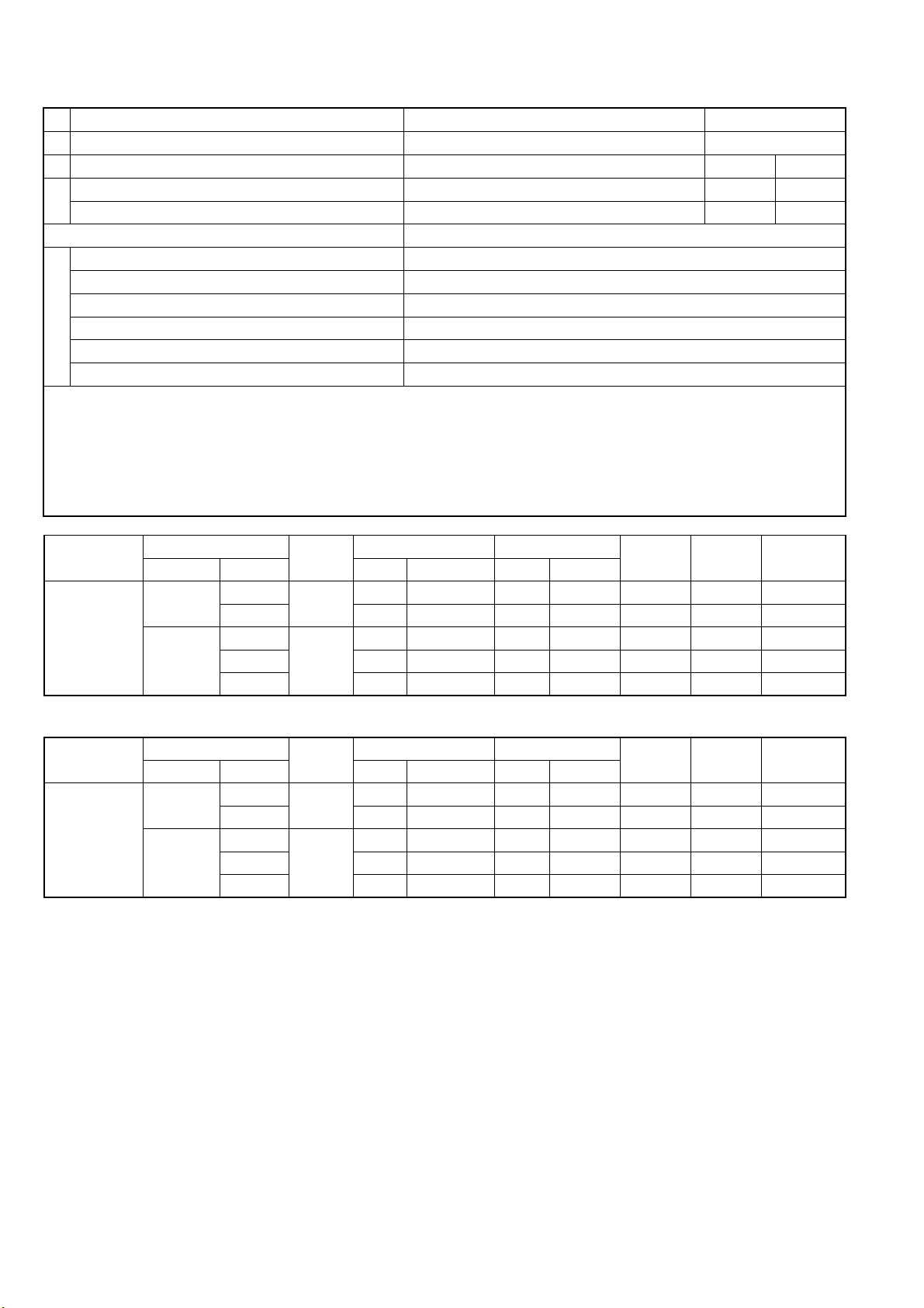
2. Specification
Model Outdoor Unit CU-2S18NBU-1
Indoor Unit Combination 3.2kW + 3.2kW
Power Source
Capacity
Running Current A 7.6 - 6.9
Cooling Operation
Maximum Current A 13.6
Starting Current A 7.8
Minimum Circuit Ampacity A 20
Dimension
Connection Cable 3 + 1 (Earth) ø1.5 mm2
Pipe Length Range (1 room) m (ft) 3 ~ 25 (9.8 ~ 82.0)
Maximum Pipe Length (Total Room) m (ft) 50 (164.0)
Refrigerant Pipe Diameter
Compressor
Air Circulation
Fan Speed High RPM 650
Heat Exchanger
Air Volume High m3/min (ft3/min) 37.2 (1313)
Refrigerant Control Device Expansion Valve
Refrigerant Oil FV50S
Refrigerant (R410A) g (oz) 1.92k (67.8)
Indoor Operation Range Cooling
Outdoor Operation Range Cooling
Electrical
Data
Noise
Net Weight kg (Ib) 69 (152)
Rated Output W 1.30k
Rated Output W 60
Tube Material Copper
Dry Bulb Wet Bulb
Power Input kW 1.45 (0.39 ~ 1.84)
EER W/W 3.37 (5.38 ~ 3.18)
BTU/hW 11.50 (18.45 ~ 10.85)
Sound Pressure Level dB-A 48
Sound Power Level dB 62
Height mm (inch) 795 (31-5/16)
Width mm (inch) 875 + 95 (34-15/32 + 3-3/4)
Depth mm (inch) 320 (12-5/8)
Liquid Side mm (inch) 6.35 (1/4)
Gas Side mm (inch) 9.52 (3/8)
Type Hermetic (Rotary)
Motor Type DC Brushless (4-poles)
Type Propeller Fan
Motor Type DC Brushless (8-poles)
Type Plate fin configuration forced draft type
Fin Material Aluminum
Row/Stage 2/36
FPI 19
Maximum °F 89.6 73.4
Minimum °F 60.8 51.8
Maximum °F 109.4 78.8
Minimum °F 60.8 51.8
kW 4.89 (2.10 ~ 5.86)
BTU/h 16700 (7200 ~ 20000)
Note
• Specifications are subject to change without notice for further improvement.
1 Phase, 208-230V, 60Hz
(Power supply from outdoor unit)
5
Page 6
• Multi split combination possibility:
o A single outdoor unit enables air conditioning of up to two separate rooms for CU-2S18NBU-1.
Outdoor Unit
CU-2S18NBU-1
A B
2.8 kW CS-S9NKUW-1 ● ●
Wall
Capacity range of connectable indoor units From 5.6 kW to 6.4 kW
1 room maximum pipe length (m (ft)) 25 (82.0)
Allowable elevation (m (ft)) 15 (49.2)
Total allowable pipe length (m (ft)) 50 (164.0)
Total pipe length for maximum chargeless length (m (ft)) 20 (65.6)
Piping Length
Additional gas amount over chargeless length (g/m (oz/ft)) 20 (0.2)
Remarks for CU-2S18NBU-1
1. At least two indoor units must be connected.
2. The total nominal cooling capacity of indoor unit that will be connected to outdoor unit must be within connectable capacity range of
indoor unit.
(as shown in the table above)
Example: The indoor units’ combination below is possible to connect to CU-2S18NBU-1. (Total nominal capacity of indoor units is
between 5.6 kW to 6.4 kW)
1) Two CS-S9NKUW-1 only. (Total nominal cooling capacity is 5.6 kW)
2) One CS-S9NKUW-1 and one CS-S12NKUW-1. (Total nominal cooling capacity is 6.0 kW)
3.2 kW CS-S12NKUW-1 ● ●
Note: “●” : Available
Outdoor Unit
CU-2S18NBU-1
Indoor unit combination Capacity (kW) Input Power (W)
Operation Class (kW)
One-room
Operation
Two-room
Operation
2.8 2.82 1.81 ~ 3.27 850 390 ~ 1020 4.5 4.1 0.5
3.2
2.8 + 2.8 4.89 2.09 ~ 5.86 1450 390 ~ 1920 7.6 6.9 0.5 + 0.5
2.8 + 3.2 4.89 2.10 ~ 5.86 1450 390 ~ 1870 7.6 6.9 0.5 + 0.6
3.2 + 3.2
Operation
Mode
Cooling
Cooling
Rating Min - Max Rating Min - Max
3.21 1.85 ~ 3.75 1000 390 ~ 1230 5.2 4.7 0.6
4.89 2.10 ~ 5.86 1450 390 ~ 1840 7.6 6.9 0.6 + 0.6
Current (A)
208V
60Hz
Current (A)
230V
60Hz
Moisture
Removal
Volume (L/h)
Outdoor Unit
CU-2S18NBU-1
Indoor unit combination Capacity (BTU/h) Input Power (W)
Operation Class (kW)
One-room
Operation
Two-room
Operation
2.8 9600 6200 ~ 11200 850 390 ~ 1020 4.5 4.1 1.1
3.2
2.8 + 2.8 16700 7100 ~ 20000 1450 390 ~ 1920 7.6 6.9 1.1 + 1.1
2.8 + 3.2 16700 7200 ~ 20000 1450 390 ~ 1870 7.6 6.9 1.1 + 1.3
3.2 + 3.2
Operation
Mode
Cooling
Cooling
Rating Min - Max Rating Min - Max
10900 6300 ~ 12800 1000 390 ~ 1230 5.2 4.7 1.3
16700 7200 ~ 20000 1450 390 ~ 1840 7.6 6.9 1.3 + 1.3
Current (A)
208V
60Hz
Current (A)
230V
60Hz
Moisture
Removal
Volume (Pt/h)
• Specifications are subject to change without notice for further improvement.
6
Page 7
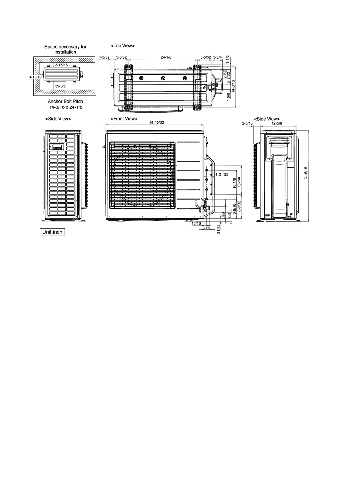
3. Dimensions
7
Page 8
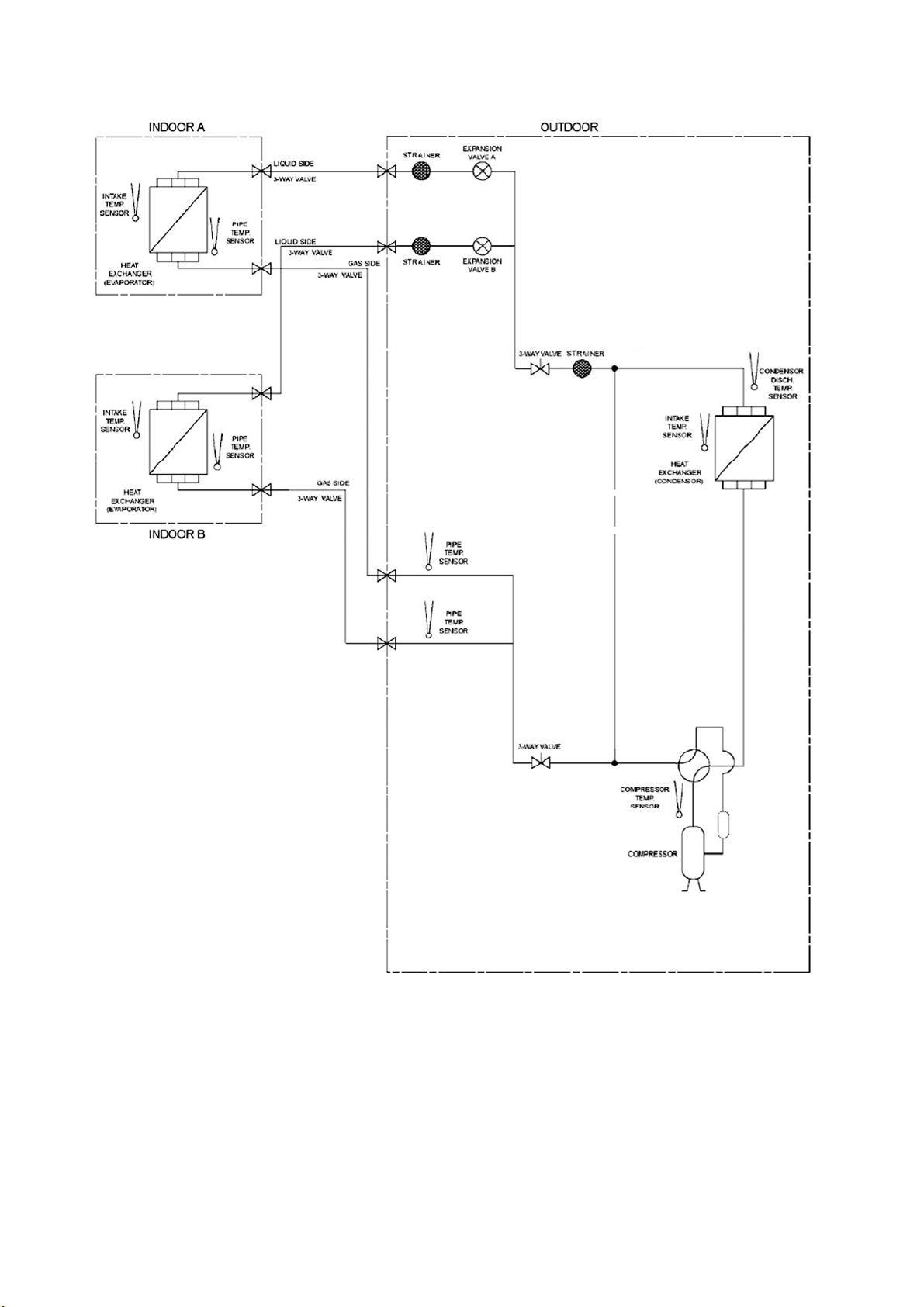
4. Refrigeration Cycle Diagram
8
Page 9
5. Block Diagram
9
Page 10
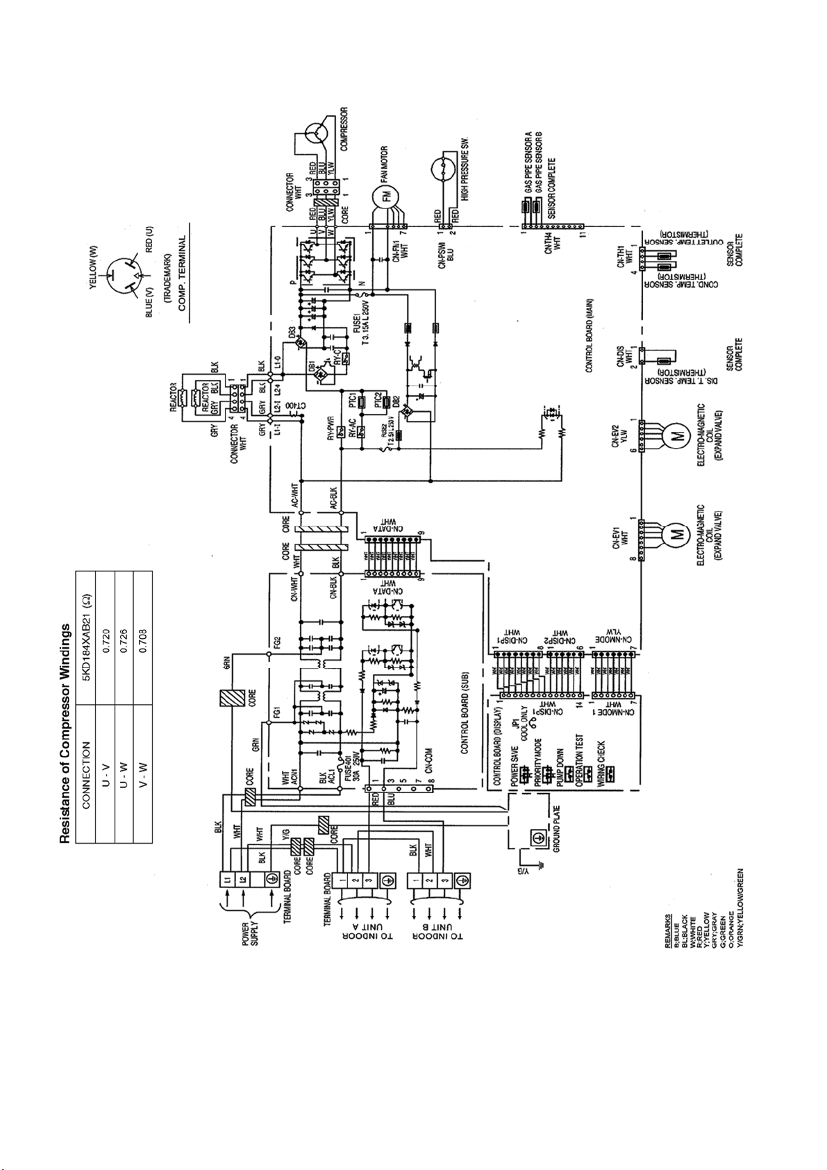
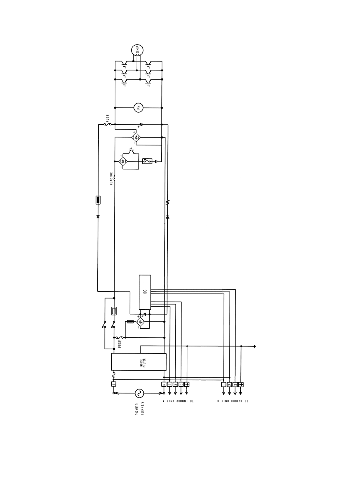
6. Wiring Connection Diagram
10
Page 11
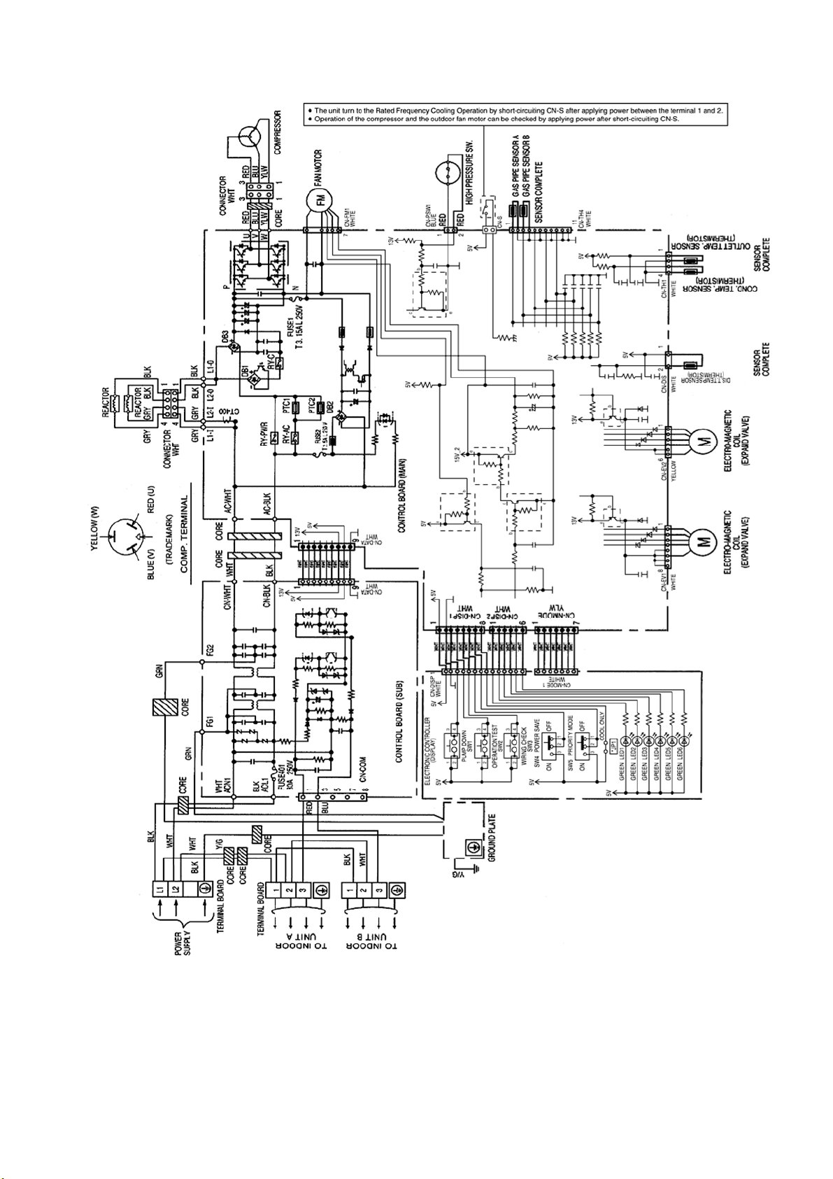
7. Electronic Circuit Diagram
11
Page 12
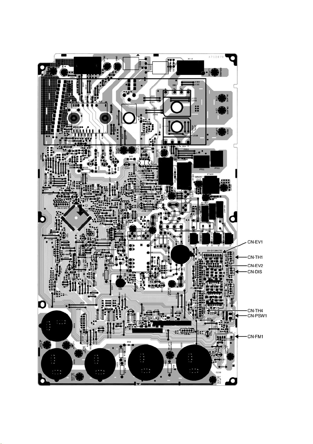
8. Printed Circuit Board
8.1 Main Printed Circuit Board
12
Page 13
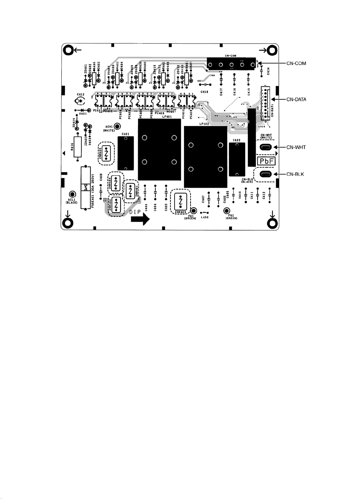
8.2 Noise Filter Printed Circuit Board
13
Page 14

9. Installation Information
9.1 Check Points
QUICK GUIDE
PIPING & ELECTRICAL SPECIFICATION
Indoor(ID) & Outdoor(OD) units:
Possible Combination Patterns
Outdoor (OD): CU-2S18NBU-1
Indoor (ID): 2 UNITS OF
CS-S9NKUW-1
Outdoor (OD): CU-2S18NBU-1
Indoor (ID): 2 UNITS OF
CS-S12NKUW-1
Outdoor (OD): CU-2S18NBU-1
Indoor (ID): 1 UNIT OF
CS-S9NKUW-1
+ 1 UNIT OF CS-S12NKUW-1
Capacity
Refrigerant
(Btu/h)
16700 R410A
Piping size
Gas Liquid
ø3/8"
(ø9.52mm)
ø1/4"
(ø6.35mm)
Standard
pipe
length
24.6 ft 49.2 ft 9.8 ft 82.0 ft 164.0 ft 65.6 ft 0.2 oz / ft
Max.
Elevation
Min. pipe
length for
each ID
unit
Max.
from
OD to
each ID
Max.
total
length
Min. total
pipe
length for
additional
gas
Additional
refrigerant
Power
supply
208/230V
60 Hz
MCA 20A
MOP 25A
Power
OD-ID
supply
connection
wire size
wire size
AWG12 AW G16
Example:
If total piping length of all installed indoor units is at 68.6 ft, the quantity of additional refrigerant should be 0.6 oz .......... (68.6 – 65.6) ft x 0.2 oz/ ft
= 0.6 oz.
14
Page 15

10. Installation Instruction
10.1 SELECT THE BEST LOCATION
10.1.1 OUTDOOR UNIT
• If an awning is built over the unit to prevent direct
sunlight or rain, be careful that heat radiation from
the condenser is not obstructed.
• There should not be any animal or plant which
could be affected by hot air discharged.
• Keep the spaces indicated by arrows from wall,
ceiling, fence or other obstacles.
• Do not place any obstacles which may cause a
short circuit of the discharged air.
• Recommended installation height for outdoor unit
should be above the seasonal snow level.
Refrigerant piping size
Outdoor Unit CU-2S18***
Liquid - side ø1/4" thickness 1/32"
Gas - side ø3/8" thickness 1/32"
Outdoor Unit CU-2S18***
Min. total piping length for
additional gas
• If total piping length of all indoor units exceeds the
minimum length listed above, additionally charge
with 0.2 oz of refrigerant (R410A) for each
additional feet of piping.
Allowable piping length of each indoor unit (min. ~ max.) 9.8 ft ~ 82.0 ft
Allowable total piping length of all indoor unit 164.0 ft or less
Height difference between indoor and outdoor unit
Height difference between indoor unit
65.6 ft
Allowable piping length
Outdoor Unit CU-2S18***
Outdoor unit located on upper side
Outdoor unit located otherwise
Outdoor unit located on upper side
Outdoor unit located otherwise
10.1.2 Outdoor Unit Installation
Diagram
• This illustration is for explanation purposes only.
* Note:
Respective indoor unit installation procedure shall
refer to instruction manual provided in the indoor
unit packaging.
49.2 ft or less
24.6 ft or less
24.6 ft or less
49.2 ft or less
15
Page 16

Outdoor Unit Installation Guidelines
• Where a wall or other obstacle is in the path of outdoor unit’s intake or exhaust airflow, follow the installation
guidelines below.
• For any of the below installation patterns, the wall height on the exhaust side should be 47 1/4" or less.
16
Page 17

10.2 INSTALL THE OUTDOOR UNIT
• After selecting the best location, start installation to Indoor/Outdoor Unit Installation Diagram.
1. Fix the unit on concrete or rigid frame firmly and horizontally with bolt nut (ø13/32").
2. When installing on a roof, please consider strong winds and earthquakes.
Please fasten the installation stand firmly with bolt or nails.
Model A B C D
CU-2S18*** 24-1/8" 5-5/32" 5/8" 14-3/16"
10.3 CONNECT THE PIPING
• Remove the control board cover (resin) from the outdoor unit by loosening three screws.
10.3.1 Connecting the Piping to Outdoor Unit
Decide piping length and then cut by using pipe cutter.
Remove burrs from cut edge. Make flare after
inserting the flare nut (locate at valve) onto the copper
pipe.
Align center of piping to valves and then tighten with
torque wrench to the specified torque as stated in the
table.
Do not overtighten, over tightening may cause gas leakage.
Piping size Torque
1/4" (0.02 ft) [18 N•m (13.3 Ibf. ft)]
3/8" (0.03 ft) [42 N•m (31.0 Ibf. ft)]
1/2" (0.04 ft) [55 N•m (40.6 Ibf. ft)]
5/8" (0.05 ft) [65 N•m (47.9 Ibf. ft)]
3/4" (0.06 ft) [100 N•m (73.8 Ibf. ft)]
10.3.2 Gas Leak Checking
Pressure test to system to 400 PSIG with dry nitrogen, in stages. Thoroughly leak check the system.
If the pressure holds, release the nitrogen and proceed to section 10.4.
17
Page 18

10.4 EVACUATION OF THE EQUIPMENT
WHEN INSTALLING AN AIR CONDITIONER, BE
SURE TO EVACUATE THE AIR INSIDE THE
INDOOR UNIT AND PIPES in the following procedure.
1. Connect a charging hose with a push pin to the
Low side of a charging set and the service port of
the gas side 3-way valve.
2. Connect the micron gauge between vacuum
pump and service port of outdoor units.
3. Turn on the power switch of the vacuum pump
and make sure that connect digital micron gauge
and to pull down to a value of 500 microns.
4. To make sure micron gauge a value 500 microns
and close the low side valve of the charging set
and turn off the vacuum pump.
5. Disconnect the vacuum pump house from the
service port of the 3-way valve.
6. Tighten the service port caps of gas side 3-way
valve at a torque of 13.3 Ibf.ft with a torque
wrench.
7. Remove the valve caps of both of the 2-way
valve and 3-way valve. Position both of the
valves to “Open” using a hexagonal wrench
(5/32").
8. Mount valve caps onto the 2-way valve and 3way valve.
• Be sure to check for gas leakage.
CAUTION
• If micron gauge value does not descend 500 microns, take the following measures:
o If the leak stops when the piping connections are tightened further, continue working from step e.
o If the leak does not stop when the connections are retightened, repair location of leak.
o Do not release refrigerant during piping work for installation and reinstallation.
o Take care when handling the liquid refrigerant, it may cause frostbite.
10.5 CONNECT THE CABLE TO THE OUTDOOR UNIT
1. Remove Control Board Cover (Metal) by
loosening 2 screws.
2. Remove Valve Cover (Metal) by loosening 2
screws.
3. Remove Plugs.
4. Fix the conduit connectors to the knock out holes
with lock-nuts, then secure them.
5. Connecting wire between indoor unit and outdoor
unit should be UL listed or CSA approved 4
conductor wires minimum AWG16 in accordance
with local electric codes.
6. Wire Connection to the power supply (208/230V
60Hz) through circuit breaker.
• Connect the UL listed or CSA approved wires
minimum AWG12 to the terminal board, and
connect to other end of the wires to circuit
breaker.
7. Connect the power supply cord and connecting
wires between indoor unit and outdoor unit
according to the diagram as shown.
18
Page 19

t
8. For wire stripping and connection requirement, refer to the diagram below.
9. Secure the power supply cord and connecting cables onto the control board with the holder.
10. Attach the control board cover (metal and resin) and valve cover back to the original position with screw.
10.6 HEAT INSULATION
se a material with good heat-resistant properties as the heat insulation for
Liquid-side pipes
CAUTION
he pipes. Be sure to insulate both the gas-side and liquid-side pipes. If the
pipes are not adequately insulated, condensation or water leakages may
occur.
Gas-side pipes
Cutting and Flaring the Piping
1 Please cut using pipe cutter and then remove the burrs.
2 Remove the burrs by using reamer. If burrs is not removed, gas leakage may be caused.
Turn the piping end down to avoid the metal powder entering the pipe.
3 Please make flare after inserting the flare nut onto the copper pipes.
Material shall
withstand 248°F or
higher
19
Page 20

11. Operation Control
11.1 Cooling Operation
11.1.1 Outdoor fan control
• When cooling operation is enabled, based on outdoor ambient temperature, fan motor control will be adjusted
according to figure below:
11.1.2 Powerful Operation 1
• During cooling operation, this control is to concentrate outdoor unit capability to the powerful operation enabled
indoor unit by temporary stop the capability supply to low load demand indoor units.
• Operation start condition:
o Powerful operation ON for targeted indoor unit.
• Operation content:
o If other indoor units (where Powerful operation are OFF) achieve setting temperature continuously for 1
minutes after received powerful command from indoor unit, then capability supply to other indoor units are
stopped for minimum 3 minutes. Capability supply stop period follows powerful operation period.
• Operation stops when comply either one of the following conditions:
o When other indoor units (where Powerful operation are OFF) is lower than setting temperature.
o When the powerful operation is OFF for all indoor units.
o When Quiet operation received from 1 indoor unit.
o When protection control starts.
11.1.3 Powerful Operation 2
• During cooling operation, this control is to provide fast cooling operation compare to normal operation.
• Operation start if all condition below are complied:
o Powerful operation ON for indoor unit.
• Operation content:
o Outdoor fan speed will adjust automatically.
o Compressor frequency will adjust automatically.
• Operation stop when comply either one of the follow conditions:
o When the powerful operation is OFF for all indoor units.
20
Page 21

12. Protection Control
12.1 Freeze Prevention control (Cool)
• When received freeze prevention signal from indoor unit, the compressor frequency changes according to indoor
heat exchanger temperature.
• When indoor unit request capability OFF due to freeze condition , immediately the capability supply to targeted
indoor unit stops.
12.2 Dew Prevention control (Cool)
• When received dew prevention signal from indoor unit, the compressor frequency changes according to indoor
intake temperature and indoor heat exchanger temperature.
12.3 Electronic Parts Temperature Rise Protection 1 (Cool)
• This control prevents electronic parts temperature rise during cooling overload condition.
• Start conditions:
o Outdoor ambient temperature is at protection region as shown in figure below:
o Outdoor unit total current is above 5.5A
• Control content
o Outdoor fan speed is adjusted accordingly.
• Control stop condition
o When outdoor ambient temperature is back to normal region.
• During this control, outdoor fan speed does not reduce for Quiet operation.
12.4 Electronic Parts Temperature Rise Protection 2 (Cool)
• This control prevents electronic parts temperature rise during cooling/dry operation.
• Start conditions:
o Total current is at protection region as shown in figure below:
• Control content
o Outdoor fan speed is adjusted accordingly.
• Control stop condition
o When total current is back to normal region.
• During this control, outdoor fan speed does not reduce for Quiet operation.
21
Page 22

12.5 Cooling overload control (Cool)
• This control detect outdoor pipe temperature and perform the compressor frequency restriction during cooling
operation.
12.6 Time Delay Safety Control (Restart Control)
• The compressor will not restart within three minutes after compressor is stopped.
• This control is not applicable if the power supply reset.
12.7 30 seconds Force Operation
• Once the compressor starts operation, it will not stop its operation for 30 seconds in order to cycle back
compressor oil.
• However, it can be stopped using remote control or Auto OFF/ON button at indoor unit.
12.8 Total Current Control
• By referring to table below, during normal (default) operation, the running current refer to Hi values and during
Power Save Mode, the running current refer to Lo values.
• When the outdoor unit total running current (AC) exceeds X value, compressor frequency will decrease.
• If the running current does not exceed X value for 5 seconds, compressor frequency will increase.
• However, if total outdoor unit running current exceeds Y value, compressor will be stopped immediately for 3
minutes.
Operation Mode
Cooling/Soft Dry (A)
Cooling/Soft Dry (B)
Hi 14.0 17.5
Lo 7.8 17.5
Hi 14.0 17.5
Lo 7.8 17.5
X (A) Y (A)
CU-2S18NBU-1
12.9 IPM (power transistor) Protection Control
• Overheating Prevention Control
o If IPM temperature rises to 176°F, outdoor fan speed will be increased.
o When the IPM temperature rises to 203°F, compressor operation will stop immediately.
o Compressor operation restarts when temperature decreases to 194°F.
o If IPM temperature detected less than -22°F, IPM is judged as open circuit (“F96” is indicated).
• DC Peak Current Control
o When IPM DC current exceeds set value of 30.0 ± 3.0 A, the compressor will stop.
o If the DC peak current detected within 30 seconds after operation starts, compressor will restart after 1
minute.
o If the DC peak current detected 30 seconds or more after operation starts, compressor will restart after 2
minute.
o Within 30 seconds after compressor restarts, if the DC peak current is exceeded set value continuously for 7
times, all indoor and outdoor relays will be cut off (“F99” is indicated).
• Error reset can be done by power supply reset.
22
Page 23

12.10 Compressor Protection Control (Gas leak detection control 1)
• Control start conditions
o For 5 minutes, the compressor continuously operates and total current is low.
o During Cooling or Soft Dry operation:
Indoor intake temperature — indoor piping temperature is below 39.2°F.
• Control content
o Compressor stops (and restart after 3 minutes)
o If the conditions above happen 4 times within 60 minutes, the unit will stop operation (“F91” is indicated).
12.11 Compressor Protection Control (Gas leak detection control 2)
• This control detect gas leakage condition to prevent compressor damage.
• Control start condition
o All connected indoor units capability supply ON.
o Compressor ON with maximum frequency.
o Compressor discharge temperature high.
• Control content
o Compressor OFF during this control (“F91” is memorized in EEPROM)
o If the above conditions happen 2 times within 60 minutes, indoor units’ Timer LED will blinks (“F91” is
indicated at all indoor units)
12.12 Valve close detection control
• This control detects 3-way valve close condition to prevent damage to refrigerant cycle.
• Start conditions:
o For all connected indoor units, if Indoor intake temperature — indoor piping temperature are between 28.4°F
and 35.6°F continuously for 5 minutes after compressor ON at first cooling operation.
o The first cooling operation is defined as cooling operation is ON for less than 8 minutes after new installation
or after pump down.
• Control content
o During this control, compressor stop, indoor units’ Timer LED will blink. (“F91” is indicated at indoor units)
• Error reset can be done by power supply reset or reset by using remote control.
12.13 Compressor discharge high pressure protection control
• This control protect by using high pressure switch during operation.
• Start conditions
o High pressure switch is activated (from normally close to open) when outdoor operation mode is cooling
during compressor running.
• Control 1 content
o Compressor stop when high pressure switch is opened and restart after high pressure switch closed. If this
condition happen 4 times within 30 minutes, “F94” is indicated.
o After 30 minutes, counter is reset if this condition does not happen for 4 times.
• Control 1 stop conditions
o Power supply reset
o Reset by using remote control
23
Page 24

13. Servicing Mode
13.1 Pump Down Operation
• Operate the pump down according to the following
procedures.
1 Confirm the valve on the liquid side and gas
side is open.
2 Press PUMP DOWN switch (SW1) on the
display printed circuit board for more than 5
seconds. Pump down (cooling) operation is
performed for 15 minutes.
3 Set the liquid side 3 way valve to close
position and wait until the pressure gauge
indicates 1.45 PSI.
4 Immediately set the gas side valve to close
position and then press the PUMP DOWN
switch (SW1) to stop the pump down
operation.
Note: Pump down operation will stop
automatically after 15 minutes if PUMP
DOWN switch (SW1) is not pressed
again.
Pump down operation cannot be
restarted until 3 minutes after
compressor is stopped.
LED 2 3 4 5 Message
○ ○ ○ ○
○ ○ ○
○ ○
Status
○
2 minutes before operation end
1 minute before operation end
Pump down operation end
Pump down operation progress
3 minutes before operation end
○ : Flashing
13.2 Test Operation
• Test operation can be carried out using OPERATION TEST switch (SW2) on the display printed circuit board
inside the outdoor unit. For cooling test, press the TEST OPERATION switch (SW2) for more than 5 seconds.
LED 1 and LED 2 will illuminate when shift into cooling test operation.
13.3 Wiring Error Check
This product capable to correcting the wiring errors
automatically by following procedures.
1 Confirm the valve on the liquid side and gas
side is open.
2 Press WIRING CHECK switch (SW3) on the
display printed circuit board for more than 10
seconds to start wiring check operation.
3 Wiring check process will complete in
approximately 10 minutes. However, wiring
check operation will not start within 3 minutes
after compressor is stopped. When outdoor air
temperature is less than 41°F or unit has
abnormality, wiring check will not start. (See
NOTE 2).
The LED 2 to 6 in display printed circuit board inside
the outdoor unit indicate whether correction is possible
or not and the status of the correction, as shown in the
table below.
LED 2 3 4 5 6 Message
ROOM A B - - -
All flashing Automatic correction impossible
LED 2, 4, 6 and LED 3,
5 alternatively flashing
Flashing one after
Status
another
Other than above Unit has abnormally (Note 4)
If automatic correct is impossible, check the indoor
unit wiring and piping manually.
Wiring check in progress
Automatic correction completed
24
Page 25

NOTE
1. For two rooms, LED 4 and 5 are not illuminated after wiring operation complete.
2. If the outdoor air temperature is less than 41°F or unit has abnormality, wiring operation will not start.
3. After wiring check operation is complete, LED indication will illuminated until normal operation starts.
4. Follow the product diagnosis procedure. (Check the diagnostic label at the control board cover.)
5. When LED 1 only illuminate, indicates that outdoor unit is operating normally.
13.4 Power Save Mode
• Power Save Mode can be enabled by pushing POWER SAVE switch (SW4) to ON before power supply ON.
• When Power Save Mode is ON, the unit can be operate at lower running current where the breaker capacity not
achieve the requirement.
13.5 Mode priority function
• Mode priority function can be enabled by pushing MODE PRIORITY switch (SW5) to ON before power supply
ON.
• When Mode Priority Function is ON, the mode priority is given to higher capacity indoor units.
25
Page 26

14. Troubleshooting Guide
14.1 Self Diagnosis Function
• The display screen of wireless remote control unit and the self-diagnosis LEDs (green) on the outdoor printed
circuit board in the outdoor unit can be used to identify the location of the problem.
Refer to the table below to identify and solve the cause of the problem, and then re-start the air conditioner
system.
• If the problem is solved and operation returns to normal.
LED 1 illuminates and others LED are off.
Diagnosis
display
H11
H12
H15
H16
H27
H28
H32
H33
H36
H37
H64
H97
Abnormality
or
Protection
control
Indoor/outdoor
abnormal
communication
Indoor unit
capacity
unmatched
Compressor
temperature
sensor
abnormality
Outdoor
current
transformer
(CT)
abnormality
Outdoor air
temperature
sensor
abnormality
Outdoor heat
exchanger
temperature
sensor 1
abnormality
Outdoor heat
exchanger
temperature
sensor 2
abnormality
Indoor/outdoor
misconnection
abnormality
Outdoor gas
pipe
temperature
sensor
abnormality
Outdoor liquid
pipe
temperature
sensor
abnormality
Outdoor high
pressure
sensor
abnormality
Outdoor fan
motor
mechanism
lock
LED 6 LED 5 LED 4 LED 3 LED 2 LED 1 Abnormality
○
○
○
○
○ ○
○ ○
○
○ ○
○
○ ○
○ ○ ○
○
○ ○
operation for
○
power supply
○
○
for 1 minutes
happen within
○
Judgment
After
1 minute
90s after
Continuous
for 5s
― ―
Continuous
for 5s
Continuous
for 5s
Continuous
for 5s
― ―
Continuous
for 5s
Continuous
for 5s
Continuous
2 times
30 minutes
Protection
Operation
Indoor fan only
operation can
start by
entering into
force cooling
operation
―
―
―
―
―
Heating
protection
operation only
Cooling
protection
operation only
―
―
Problem Check location
• Indoor/outdoor
Indoor/outdoor
communication
not establish
Total indoor
capability more
than maximum
limit or less than
minimum limit, or
number of
indoor unit less
than two
Compressor
temperature
sensor open or
short circuit
Current
transformer
faulty or
compressor
faulty
Outdoor air
temperature
sensor open or
short circuit
Outdoor heat
exchanger
temperature
sensor 1 open or
short circuit
Outdoor heat
exchanger
temperature
sensor 2 open or
short circuit
Indoor and
outdoor rated
voltage different
Outdoor gas pipe
temperature
sensor open or
short circuit
Outdoor liquid
pipe temperature
sensor open or
short circuit
High pressure
sensor open
circuit during
compressor stop
Outdoor fan motor
lock or feedback
abnormal
wire terminal
• Indoor/outdoor
PCB
• Indoor/outdoor
connection wire
• Indoor/outdoor
connection wire
• Indoor/outdoor
PCB
• Specification and
combination table
in catalogue
• Compressor
temperature
sensor lead wire
and connector
• Outdoor PCB
faulty or
compressor faulty
• Outdoor air
temperature
sensor lead wire
and connector
• Outdoor heat
exchanger
temperature
sensor 1 lead wire
and connector
• Outdoor heat
exchanger
temperature
sensor 2 lead wire
and connector
• Indoor and
outdoor units
check
• Outdoor gas pipe
temperature
sensor lead wire
and connector
• Outdoor liquid
pipe temperature
sensor lead wire
and connector
• High pressure
sensor
• Lead wire and
connector
• Outdoor fan motor
lead wire and
connector
• Fan motor lock or
block
26
Page 27

Diagnosis
display
H98
H99
F11
F17
F90
F91
F93
F94
F95
F96
F97
F98
F99
Abnormality
or
Protection
control
Indoor high
pressure
protection
Indoor
operating unit
freeze
protection
4-way valve
switching
abnormality
Indoor standby
units freezing
abnormality
Power factor
correction
(PFC) circuit
protection
Refrigeration
cycle
abnormality
Compressor
abnormal
revolution
Compressor
discharge
pressure
overshoot
protection
Outdoor cooling
high pressure
protection
Power transistor
module
overheating
protection
Compressor
overheating
protection
Total running
current
protection
Outdoor direct
current (DC)
peak detection
LED 6 LED 5 LED 4 LED 3 LED 2 LED 1 Abnormality
○ ○ ○
○ ○ ○
○ ○ ○ ○
○
○
○
○
○
○
○
○
○ ○
○ ○
○
○
○ ○
○ ○ ○
○
○ ○
Judgment
― ―
― ―
4 times
happen within
30 minutes
3 times
happen within
40 minutes
4 times
happen within
○
10 minutes
2 times
happen within
20 minutes
4 times
happen within
20 minutes
4 times
happen within
30 minutes
4 times
happen within
○
20 minutes
4 times
happen within
30 minutes
3 times
happen within
30 minutes
3 times
happen within
20 minutes
Continuous
happen for 7
○
times
Protection
Operation
―
―
―
―
―
―
―
―
―
―
―
Problem Check location
Indoor high
pressure
protection
(Heating)
Indoor freeze
protection
(Cooling)
4-way valve
Switching
abnormal
Wrong wiring and
connecting pipe,
expansion valve
leakage, indoor
heat exchanger
sensor open circuit
Power factor
correction circuit
abnormal
Refrigeration
cycle abnormal
Compressor
abnormal
revolution
Compressor
discharge pressure
overshoot
Cooling high
pressure
protection
Power transistor
module overheat
Compressor
overheat
Total current
protection
Power transistor
module current
protection
• Check indoor heat
exchanger
• Air filter dirty
• Air circulation
short circuit
• Check indoor heat
exchanger
• Air filter dirty
• Air circulation
short circuit
• 4-way valve
• Lead wire and
connector
• Check indoor/
outdoor
connection wire
and pipe
• Indoor heat
exchanger sensor
lead wire and
connector
• Expansion valve
lead wire and
connector
• Outdoor PCB
faulty
• Insufficient
refrigerant or valve
close
• Power transistor
module faulty or
compressor lock
• Check
refrigeration
system
• Check
refrigeration
system
• Outdoor air circuit
• PCB faulty
• Outdoor air circuit
(fan motor)
• Insufficient
refrigerant
• Check
refrigeration
system
• Power source or
compressor lock
• Power transistor
module faulty or
compressor lock
LED 1 illuminate is indicated that outdoor unit is operating normally. If the LED 1 is switched off or flashing, check the power
supply and self-diagnosis indication.
---------- Illuminate
●
---------- Flashing
○
Blank
---------- OFF
27
Page 28

15. Disassembly and Assembly Instructions
High Voltages are generated in the electrical parts area by the capacitor. Ensure that the capacitor has discharged sufficiently before proceeding
with repair work. Failure to heed this caution may result in electric shocks.
15.1 Outdoor Unit Removal Procedure
Caution! When handling electronic controller, be careful of electrostatic discharge.
15.1.1 Removing the Cabinet Top Plate and Cabinet Front Plate
1. Remove the cabinet top plate (remove the 8 screws).
2. Remove the 8 screws (1 on the center, 3 at the top and 4
at the bottom) securing the cabinet front plate, release
the 2 hooks (1 each at the left and right), and pull the
cabinet front plate toward front side.
WARNING
15.1.2 Remove the Control Board Cover and Particular Plates
3. Remove the control board cover (remove 3 screw).
4. Remove the particular plate (remove 2 screw).
5. Remove the particular plate (remove 2 screw).
28
Page 29

15.1.3 Removing the Control P.C. Board
6. Remove the drip proof cover.
7. Disconnect the connectors (lead wires of the compressor,
sensor, and others).
8. Remove the screw at the right side of the control box,
and pull out the entire control box.
9. Release the control P.C. Board tab to remove the control
P.C. Board.
15.1.4 Removing the Propeller Fan and Fan Motor
1. Follow the steps in 15.1.1 for removing the cabinet top
plate and cabinet front plate.
2. Remove the propeller fan by removing the nut turning
clockwise at its center.
29
Page 30

3. Disconnect the fan motor connector from the control P.C.
Board.
4. Loosen the 4 fan motor mounting screws then remove
the fan motor.
30
Page 31

16. Technical Data
16.1 Operation Characteristics
16.1.1 CS-S9NKUW-1 CU-2S18NBU-1
• Cooling Characteristic
o Room temperature: 81°F (DBT), 66°F (WBT)
o Operation condition: High fan speed
o Piping length: 24.6ft
o Compressor Freq: Fc
31
Page 32

• Piping Length Characteristic
o Room temperature: 81°F (DBT), 66°F (WBT)
o Operation condition: High fan speed
o Outdoor temperature: 95°F (DBT)
o Compressor Freq: Fc
32
Page 33

16.1.2 CS-S9NKUW-1x2 CU-2S18NBU-1
• Cooling Characteristic
o Room temperature: 81°F (DBT), 66°F (WBT)
o Operation condition: High fan speed
o Piping length: 24.6ft
o Compressor Freq: Fc
33
Page 34

• Piping Length Characteristic
o Room temperature: 81°F (DBT), 66°F (WBT)
o Operation condition: High fan speed
o Outdoor temperature: 95°F (DBT)
o Compressor Freq: Fc
34
Page 35

16.1.3 CS-S12NKUW-1 CU-2S18NBU-1
• Cooling Characteristic
o Room temperature: 81°F (DBT), 66°F (WBT)
o Operation condition: High fan speed
o Piping length: 24.6ft
o Compressor Freq: Fc
35
Page 36

• Piping Length Characteristic
o Room temperature: 81°F (DBT), 66°F (WBT)
o Operation condition: High fan speed
o Outdoor temperature: 95°F (DBT)
o Compressor Freq: Fc
36
Page 37

16.1.4 CS-S12NKUW-1x2 CU-2S18NBU-1
• Cooling Characteristic
o Room temperature: 81°F (DBT), 66°F (WBT)
o Operation condition: High fan speed
o Piping length: 24.6ft
o Compressor Freq: Fc
37
Page 38

• Piping Length Characteristic
o Room temperature: 81°F (DBT), 66°F (WBT)
o Operation condition: High fan speed
o Outdoor temperature: 95°F (DBT)
o Compressor Freq: Fc
38
Page 39

16.1.5 CS-S12NKUW-1+CS-S9NKUW-1 CU-2S18NBU-1
• Cooling Characteristic
o Room temperature: 81°F (DBT), 66°F (WBT)
o Operation condition: High fan speed
o Piping length: 24.6ft
o Compressor Freq: Fc
39
Page 40

• Piping Length Characteristic
o Room temperature: 81°F (DBT), 66°F (WBT)
o Operation condition: High fan speed
o Outdoor temperature: 95°F (DBT)
o Compressor Freq: Fc
40
Page 41

17. Exploded View and Replacement Parts List
Note
The above exploded view is for the purpose of parts disassembly and replacement.
The non-numbered parts are not kept as standard service parts.
41
Page 42

REF. NO. DESCRIPTION & NAME QTY. CU-2S18NBU-1 REMARK
1 BASE PAN ASS'Y 1 CWD52K1240A
2 SOUND-PROOF BOARD 1 CWH151230
3 FAN MOTOR BRACKET 1 CWD541127
5 CONDENSER COMPLETE 1 CWB32C2925
6 FAN MOTOR 1 EHDS80CAC O
8 PROPELLER FAN 1 CWH00K1006
9 NUT - PROPELLER FAN 1 CWH561038J
10 COMPRESSOR 1 5KD184XAB21
11 PACKING 3 CWB81043
12 ANTI - VIBRATION BUSHING 3 CWH50055
13 NUT - COMPRESSOR 3 CWH561049
16 ACUMULATOR 1 CWB131050
17 3-WAY VALVE (LIQUID) 2 CWB011601 O
18 3-WAY VALVE(GAS) 2 CWB011602 O
19 HOLDER COUPLING 1 CWH351170
20 STRAINER 1 CWB111062
21 STRAINER 2 CWB111063
22 EXPANSION VALVE 2 CWB051029
23 4-WAYS VALVE 1 CWB001057
24 DISCHARGE MUFFLER 1 CWB121042
25 PRESSURE SWITCH 1 CWA101007
26 UNION NUT 4 CWT251030
27 UNION NUT 4 CWT251031
28 SOUND PROOF MATERIAL 1 CWG302246
29 SOUND PROOF MATERIAL 1 CWG302520
30 SOUND PROOF MATERIAL 1 CWG302521
31 SOUND PROOF MATERIAL 1 CWG302522
32 SENSOR-COMPLETE 1 CWA50C2722 O
34 V-COIL COMPLETE 1 CWA43C2381 O
35 V-COIL COMPLETE 1 CWA43C2382 O
39 SENSOR-COMPLETE 1 CWA50C2710 O
40 SENSOR-COMPLETE 1 CWA50C2691 O
42 HOLDER-SENSOR 1 CWH32074
43 ELECTRONIC CONTROLLER-MAIN 1 CWA73C6132R O
44 ELECTRONIC CONT.-NOISE FILTER 1 CWA745975 O
47 REACTOR 1 G0C403J00001 O
48 TERMINAL BOARD ASS'Y 1 CWA28K1195 O
49 TERMINAL BOARD ASS'Y 2 CWA28K1196 O
50 CONTROL BOARD COVER(TOP) 1 CWH131333
52 CABINET TOP PLATE 1 CWE031131A
53 CONTROL BOARD COVER COMPLETE 1 CWH13C1209
54 CABINET FRONT PLATE CO. 1 CWE06K1071
55 CABINET SIDE PLATE( L ) 1 CWE041489A
56 CABINET SIDE PLATE( R ) 1 CWE041499A
57 WIRE NET 1 CWD041128A
58 HANDLE 1 CWE161010
60 INSTALLATION INSTRUCTION 1 CWF615180
61 MANIFOLD TUBE ASS'Y(GAS) 1 CWT07K1522
62 TUBE ASS'Y (LIQUID 1) 1 CWT026316
63 TUBE ASS'Y (LIQUID 2) 1 CWT026872
64 CONTROL BOARD COVER 1 CWH131364
65 CLIP FOR SENSOR HOLDER 3 CWH711010
66 BAG 1 CWG861154
67 BASE BOARD-COMPLETE 1 CWG62C1081
68 SHOCK ABSORBER (RIGHT) 1 CWG712879
42
Page 43

REF. NO. DESCRIPTION & NAME QTY. CU-2S18NBU-1 REMARK
69 SHOCK ABSORBER (LEFT) 1 CWG712880
70 C.C.CASE 1 CWG565609
76 TERMINAL COVER 1 CWH171035
77 NUT - TERMINAL COVER 2 CWH7080300J
(Note)
• All parts are supplied from PHAAM, Malaysia (Vendor Code: 00029488).
• “O” marked parts are recommended to be kept in stock.
Printed in Malaysia
SB1111-0
43
 Loading...