

Panasonic CU-2E18SBU-5 Service Manual
© Panasonic Corporation 2017
Order No: PAPAMY1702089CE
Outdoor Unit
CU-2E18SBU-5
Destination
USA
CANADA
Please file and use this manual together with the service manual for Model No. CS-ME5RKUA CS-ME7RKUA, CS-E9RKUA
CS-E12RKUA, CS-ME9SB4U, CS-E12RB4UW, CS-ME5SD3UA CS-ME7SD3UA, CS-E9SD3UAW CS-E12SD3UAW, Order No.
PAPAMY1503085CE, PAPAMY1501049CE, PAPAMY1604059CE, PAPAMY1503095CE, PAPAMY1604056CE,
PAPAMY1604052CE.
WARNING
This service information is designed for experienced repair technicians only and is not designed for use by the general public.
It does not contain warnings or cautions to advise non-technical individuals of potential dangers in attempting to service a product.
Products powered by electricity should be serviced or repaired only by experienced professional technicians. Any attempt to
service or repair the products dealt with in this service information by anyone else could result in serious injury or death.
PRECAUTION OF LOW TEMPERATURE
In order to avoid frostbite, be assured of no refrigerant leakage during the installation or repairing of refrigerant circuit.

2
TABLE OF CONTENTS
PAGE PAGE
1. Safety Precautions ............................................. 3
2. Specifications ..................................................... 5
2.1 CU-2E18SBU-5 ............................................ 5
3. Dimensions ....................................................... 10
4. Refrigeration Cycle Diagram ........................... 11
5. Block Diagram .................................................. 12
6. Wiring Connection Diagram ............................ 13
7. Electronic Circuit Diagram .............................. 14
8. Printed Circuit Board ....................................... 15
8.1 Main Printed Circuit Board ......................... 15
8.2 Noise Filter Printed Circuit Board ............... 16
8.3 Display Printed Circuit Board ..................... 16
9. Installation Information .................................... 17
9.1 Check Points .............................................. 17
10. Installation Instruction ..................................... 18
10.1 Accessories Supplied with Outdoor
Unit ............................................................. 18
10.2 Cutting and Flaring the Piping .................... 18
10.3 Select the Best Location ............................. 19
10.4 Install the Outdoor Unit ............................... 20
10.5 Connect the Piping ..................................... 20
10.6 Evacuation of the Equipment ..................... 21
10.7 Connect the Cable to the Outdoor Unit ...... 22
10.8 Heat Insulation ............................................ 22
11. Operation Control ............................................. 23
11.1 Cooling Operation ....................................... 23
11.2 Heating Operation ...................................... 24
12. Simultaneous Operation Control .................... 25
13. Protection Control ............................................ 26
13.1 Freeze Prevention Control (Cool) ............... 26
13.2 Dew Prevention Control (Cool) ................... 26
13.3 Electronic Parts Temperature Rise
Protection 1 (Cool) ...................................... 26
13.4 Electronic Parts Temperature Rise
Protection 2 (Cool) ...................................... 26
13.5 Cooling Overload Control (Cool) ................ 27
13.6 Heating Overload Control (Heat) ................ 27
13.7 Extreme Low Temperature Compressor
Low Pressure Protection Control (Heat) ..... 28
13.8 Deice Control .............................................. 28
13.9 Time Delay Safety Control (Restart
Control) ....................................................... 28
13.10 30 seconds Force Operation ...................... 28
13.11 Total Current Control .................................. 28
13.12 IPM (power transistor) Protection
Control ........................................................ 29
13.13 Compressor Protection Control (Gas leak
detection control 1) ..................................... 29
13.14 Compressor Protection Control (Gas leak
detection control 2) ..................................... 29
13.15 Valve Close Detection Control ................... 29
13.16 Compressor Discharge High Pressure
Protection Control .......................................30
14. Servicing Mode .................................................31
14.1 CU-2E18SBU-5 ..........................................31
15. Troubleshooting Guide ....................................33
15.1 Self Diagnosis Function ..............................33
16. Disassembly and Assembly Instructions ......36
16.1 Outdoor Unit Removal Procedure ..............36
17. Technical Data ..................................................39
17.1 Cool Mode Performance Data ....................39
17.2 Heat Mode Performance Data ....................41
18. Service Data ......................................................43
18.1 Operation Characteristics ...........................43
19. Exploded View and Replacement Parts
List .....................................................................47

3
1. Safety Precautions
Read the following “SAFETY PRECAUTIONS” carefully before installation.
Electrical work must be installed by a licensed electrician. Be sure to use the correct rating of the power plug and main circuit
for the model to be installed.
The caution items stated here must be followed because these important contents are related to safety. The meaning of each
indication used is as below. Incorrect installation due to ignoring of the instruction will cause harm or damage, and the
seriousness is classified by the following indications.
WARNING
This indication shows the possibility of causing death or serious injury.
CAUTION
This indication shows the possibility of causing injury or damage to properties only.
The items to be followed are classified by the symbols:
Symbol with white background denotes item that is PROHIBITED from doing.
Symbol with dark background denotes item that must be carried out.
Carry out test running to confirm that no abnormality occurs after the installation. Then, explain to user the operation, care
and maintenance as stated in instructions. Please remind the customer to keep the operating instructions for future reference.
WARNING
1.
Do not install outdoor unit near handrail of veranda. When installing air-conditioner unit on veranda of a high rise building, child
may climb up to outdoor unit and cross over the handrail causing an accident.
2.
Do not use unspecified cord, modified cord, joint cord or extension cord for power supply cord. Do not share the single outlet
with other electrical appliances. Poor contact, poor insulation or over current will cause electrical shock or fire.
3. Do not tie up the power supply cord into a bundle by band. Abnormal temperature rise on power supply cord may happen.
4.
Do not insert your fingers or other objects into the unit, high speed rotating fan may cause injury.
5.
Do not sit or step on the unit, you may fall down accidentally.
6. Keep plastic bag (packaging material) away from small children, it may cling to nose and mouth and prevent breathing.
7.
When installing or relocating air conditioner, do not let any substance other than the specified refrigerant, eg. air etc. mix into
refrigeration cycle (piping). Mixing of air etc will cause abnormal high pressure in refrigeration cycle and result in explosion,
injury etc.
8. Do not add or replace refrigerant other than specified type. It may cause product damage, burst and injury etc.
9.
For R410A model, use piping, flare nut and tools which is specified for R410A refrigerant. Using of existing (R22) piping,
flare nut and tools may cause abnormally high pressure in the refrigerant cycle (piping), and possibly result in explosion and
injury.
Thickness for copper pipes used with R410A must be more than 1/32" (0.8 mm). Never use copper pipes thinner than
1/32" (0.8 mm).
It is desirable that the amount of residual oil less than 0.0008 oz/ft (40 mg/10 m).
10.
Engage authorized dealer or specialist for installation. If installation done by the user is incorrect, it will cause water leakage, electrical
shock or fire.
11. Install according to this installation instructions strictly. If installation is defective, it will cause water leakage, electrical shock or fire.
12.
Use the attached accessories parts and specified parts for installation. Otherwise, it will cause the set to fall, water leakage, fire or
electrical shock.
13.
Install at a strong and firm location which is able to withstand the set’s weight. If the strength is not enough or installation is not properly
done, the set will drop and cause injury.
14.
For installation work, follow all electrical, building, plumbing, local codes, regulations and these installation instructions. If electrical circuit
capacity is not enough or a defect is found in electrical work, it will cause electrical shock or fire.
15.
Do not use spliced wires for indoor/outdoor connection cable. Use the specified indoor/outdoor connection cable, refer to instruction
INDOOR/OUTDOOR UNIT ELECTRICAL WIRING and connect tightly for indoor/outdoor connection. Clamp the cable so that no
external force will have impact on the terminal. If connection or fixing is not perfect, it will cause heat-up or fire at the connection.
16.
Wire routing must be properly arranged so that control board cover is fixed properly. If control board cover is not fixed perfectly, it will
cause fire or electrical shock.
17.
This equipment must installed with an Earth Leakage Circuit Breaker (ELCB) or Ground Fault Current Interrupter (GFCI) or Appliance
Leakage Current Interrupter (ALCI) that has been certified by an NRTL Certified Testing Agency and that is suitable for the voltages and
amperages involved. Otherwise, if may cause electrical shock and fire in case of equipment breakdown.
4
18.
During installation, install the refrigerant piping properly before running the compressor. Operation of compressor without fixing
refrigeration piping and valves at opened condition will cause suck-in of air, abnormal high pressure in refrigeration cycle and result in
explosion, injury etc.
19.
During pump down operation, stop the compressor before removing the refrigeration piping. Removal of refrigeration piping while
compressor is operating and valves are opened will cause suck-in of air, abnormal high pressure in refrigeration cycle and result in
explosion, injury etc.
20.
Tighten the flare nut with torque wrench according to specified method. If the flare nut is over-tightened, after a long period, the flare
may break and cause refrigerant gas leakage.
21.
After completion of installation, confirm there is no leakage of refrigerant gas. It may generate toxic gas when the refrigerant comes into
contact with fire.
22. Ventilate if there is refrigerant gas leakage during operation. It may cause toxic gas when the refrigerant comes into contact with fire.
23.
This equipment must be properly earthed. Earth line must not be connected to gas pipe, water pipe, earth of lightning rod and telephone.
Otherwise, it may cause electrical shock in case of equipment breakdown or insulation breakdown.
CAUTION
1.
Do not install the unit at place where leakage of flammable gas may occur. In case gas leaks and accumulates at surrounding
of the unit, it may cause fire.
2.
Do not release refrigerant during piping work for installation, re-installation and during repairing a refrigeration parts. Take care
of the liquid refrigerant, it may cause frostbite.
3. Do not install this appliance in a laundry room or other location where water may drip from the ceiling, etc.
4.
Do not touch the sharp aluminium fin, sharp parts may cause injury.
5.
Carry out drainage piping as mentioned in installation instructions. If drainage is not perfect, water may enter the room and damage the
furniture.
6. Select an installation location which is easy for maintenance.
7.
Power supply connection to the room air conditioner.
Power supply cord shall be UL listed or CSA approved 3 conductor with minimum AWG12 wires.
Power supply point should be in an easily accessible place for power disconnection in case of emergency.
In some countries, permanent connection of this air conditioner to the power supply is prohibited.
Fix power supply connection to a circuit breaker for permanent connection.
Use NRTL approved fuse or circuit breaker (rating refers to name plate) for permanent connection.
8.
Installation work.
It may take two people to carry out the installation work.

5
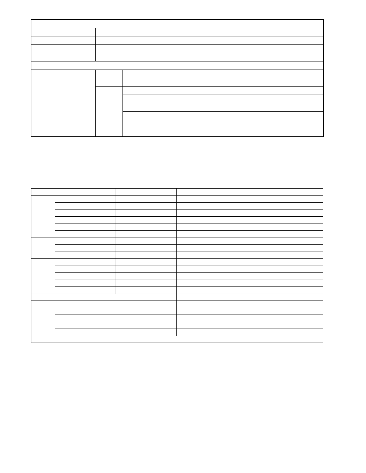
2. Specifications
2.1 CU-2E18SBU-5
Item Unit OUTDOOR UNIT
Indoor Unit Combination 2.5kW + 2.5kW
Power Source
1 Phase, 208 – 230V, 60Hz (Power supply from
outdoor unit)
Cooling Operation
Capacity
kW 4.89 (2.10 ~ 5.86)
BTU/h 16700 (7200 ~ 20000)
Electrical
Data
Running Current A 6.6 - 6.0
Power Input kW 1.33 (0.36 ~ 1.69)
EER W/W 3.68 (5.83 ~ 3.47)
BTU/hW 12.55 (20.00 ~ 11.85)
Noise
Sound Pressure Level dB-A 48
Sound Power Level dB 62
Power Factor % 97 / 96
Heating Operation
Capacity
kW 5.94 (2.11 ~ 7.20)
BTU/h 20200 (7200 ~ 24600)
Electrical
Data
Running Current A 8.5 - 7.8
Power Input kW 1.75 (0.40 ~ 2.18)
COP W/W 3.38 (5.28 ~ 3.30)
BTU/hW 11.50 (18.00 ~ 11.30)
Noise
Sound Pressure Level dB-A 49
Sound Power Level dB 63
Power Factor % 99 / 98
Maximum Current A 13.6
Maximum Input Power W 3.04k
Starting Current A 8.5
Minimum Circuit Ampacity A 20
Maximum Overcurrent Protection A 25
Dimension
Height mm (inch) 795 (31-5/16)
Width mm (inch) 875 + 95 (34-15/32 + 3-3/4)
Depth mm (inch) 320 (12-5/8)
Net Weight kg (lb) 71 (157)
Connection cable 4 x AWG12
Pipe Length Range (1 room) m (ft) 3 ~ 25 (9.8 ~ 82.0)
Maximum Pipe Length (Total Room) m (ft) 50 (164.0)
Refrigerant Pipe Diameter
Liquid Side mm (inch) 6.35 (1/4)
Gas Side mm (inch) 9.52 (3/8)
Compressor
Type Hermetic Motor
Motor Type DC Brushless (4-poles)
Rated Output W 1.30k
Air Circulation
Type Propeller Fan
Motor Type DC Brushless (8-poles)
Rated Output W 60
Fan Speed High RPM 580
Heat Exchanger
Type Plate fin configuration forced draft type
Tube Material Copper
Fin Material Aluminum (Blue Coat)
Row/Stage 2/36
FPI 19
6
Item Unit OUTDOOR UNIT
Air Volume High m3/min (ft3/min) 41.0 (1447)
Refrigerant Control Device Expansion Valve
Refrigerant Oil cm3 FV50S (900)
Refrigerant (R410A) g (oz) 2.23k (78.7)
Dry Bulb Wet Bulb
Indoor Operation Range
Cooling
Maximum °C (°F) 32 (89.6) 23 (73.4)
Minimum °C (°F) 16 (60.8) 11 (51.8)
Heating
Maximum °C (°F) 30 (86.0) —
Minimum °C (°F) 16 (60.8) —
Outdoor Operation Range
Cooling
Maximum °C (°F) 46 (114.8) 26 (78.8)
Minimum °C (°F) -10 (14.0) — / —
Heating
Maximum °C (°F) 24 (75.2) 18 (64.4)
Minimum °C (°F) -20.56 (-5.0) -21.56 (-6.8)
Note
Specifications are subject to change without notice for further improvement.
Multi split combination possibility:
o A single outdoor unit enables air conditioning of up to two separate rooms for CU-2E18SBU-5.
Multi Zone Capacity (kW) CU-2E18SBU-5
Wall
CS-ME5RKUA 1.6 ●
CS-ME7RKUA 2.0 ●
CS-E9RKUAW 2.5 ●
CS-E12RKUAW 3.2 ●
CS-E18RKUAW 5.0 -
CS-E24RKUAW 7.0 -
4-Way
CS-ME9SB4U 2.5 ●
CS-E12RB4UW 3.2 ●
CS-E18RB4UW 5.0 -
Ducted
CS-ME5SD3UA 1.6 ●
CS-ME7SD3UA 2.0 ●
CS-E9SD3UAW 2.5 ●
CS-E12SD3UAW 3.2 ●
CS-E18SD3UAW 5.0 -
Capacity range of connectable indoor units From 3.2 kW to 6.4 kW
Piping Length
1 room maximum pipe length (m (ft)) 25 (52.0)
Allowable elevation (m (ft)) 15 (49.2)
Total allowable pipe length (m (ft)) 50 (164.0)
Total pipe length for maximum chargeless length (m (ft)) 20 (65.6)
Additional gas amount over chargeless length (g/m (oz/ft)) 20 (0.2)
Note: “●” : Available
Specifications are subject to change without notice for further improvement.
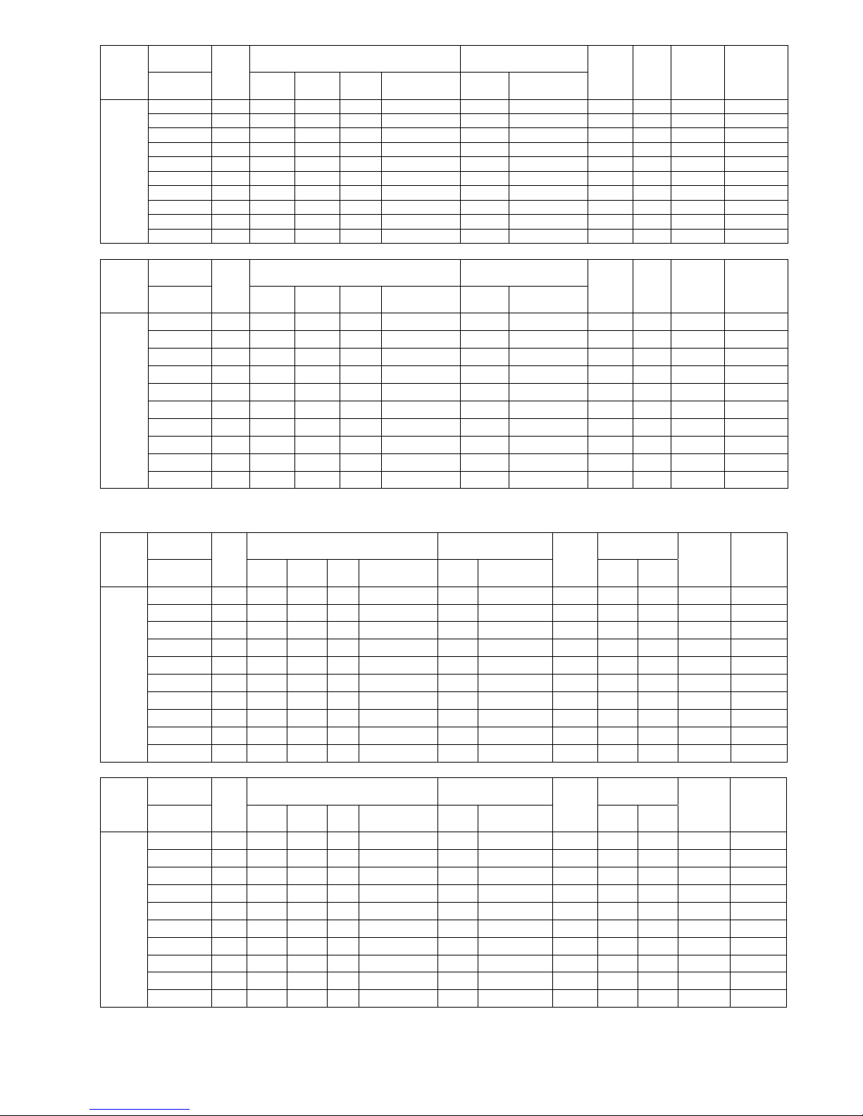
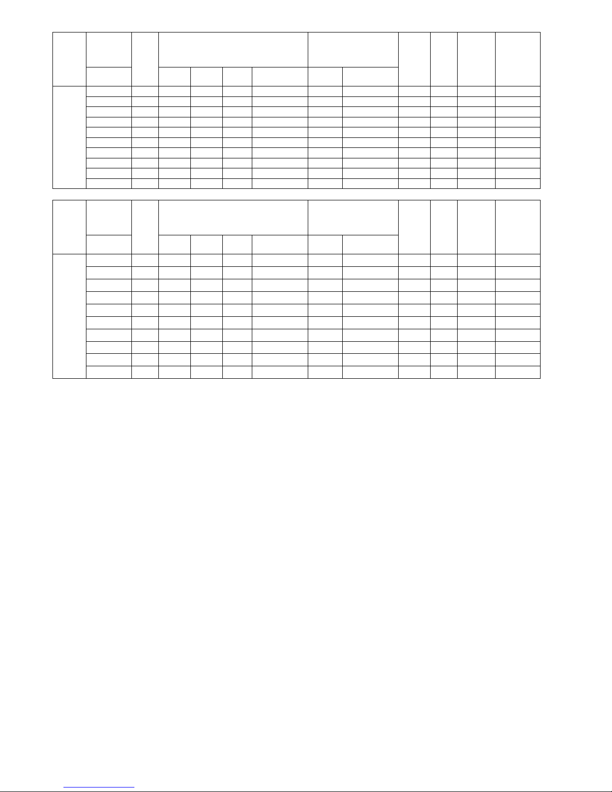
7
Indoor unit
capacity
Total
Cooling Capacity (kW) Input Power (W)
EER
W/W
SEER
Current,
230V (A)
Moisture
Removal
Volume (l/h)
Cooling
Room A Room
B
Total min ~ max Rating min ~ max
2 Room
1.6 + 1.6 3.2 1.620 1.620 3.24 2.10 ~ 3.89 770 360 ~ 960 4.20 19.00 3.6 0.3 + 0.3
1.6 + 2.0 3.6 1.613 2.017 3.63
2.10 ~ 4.36
860
360 ~ 1110
4.22 19.00 4.0 0.3 + 0.4
1.6 + 2.5 4.1 1.616 2.524 4.14 2.10 ~ 4.97 1030 360 ~ 1370 4.02 19.00 4.7 0.3 + 0.5
1.6 + 3.2 4.8 1.610 3.220 4.83 2.10 ~ 5.80 1290 360 ~ 1680 3.74 19.00 5.8 0.3 + 0.6
2.0 + 2.0 4.0 2.010 2.010 4.02 2.10 ~ 4.82 980 360 ~ 1310 4.10 19.00 4.5 0.4 + 0.4
2.0 + 2.5 4.5 2.013 2.517 4.53
2.10 ~ 5.44
1210
360 ~ 1580
3.74 19.00 5.5 0.4 + 0.5
2.0 + 3.2 5.2 1.881 3.009 4.89 2.10 ~ 5.86 1330 360 ~ 1690 3.68 19.00 6.0 0.4 + 0.6
2.5 + 2.5 5.0 2.445 2.445 4.89 2.10 ~ 5.86 1330 360 ~ 1690 3.68 19.00 6.0 0.5 + 0.5
2.5 + 3.2 5.7 2.145 2.745 4.89 2.10 ~ 5.86 1330 360 ~ 1690 3.68 19.00 6.0 0.5 + 0.6
3.2 + 3.2 6.4 2.445 2.445 4.89
2.10 ~ 5.86
1330
360 ~ 1690
3.68 19.00 6.0 0.6 + 0.6
Indoor unit
capacity
Total
Cooling Capacity (BTU/hr) Input Power (W)
EER
Btu/h.W
SEER
Current,
230V (A)
Moisture
Removal
Volume (l/h)
Cooling
Room A Room
B
Total min ~ max Rating min ~ max
2 Room
1.6 + 1.6 3.2 5500 5500 11000 7200 ~ 13300 770 360 ~ 960
14.25
19.00 3.6 0.3 + 0.3
1.6 + 2.0 3.6 5511 6889 12400 7200 ~ 14900 860 360 ~ 1110
14.40
19.00 4.0 0.3 + 0.4
1.6 + 2.5 4.1 5502 8598 14100
7200 ~ 16900
1030
360 ~ 1370
13.65
19.00 4.7 0.3 + 0.5
1.6 + 3.2 4.8 5500 11000 16500 7200 ~ 19800 1290 360 ~ 1680
12.75
19.00 5.8 0.3 + 0.6
2.0 + 2.0 4.0 6850 6850 13700 7200 ~ 16400 980 360 ~ 1310
13.95
19.00 4.5 0.4 + 0.4
2.0 + 2.5 4.5 6844 8556 15400 7200 ~ 18500 1210 360 ~ 1580
12.70
19.00 5.5 0.4 + 0.5
2.0 + 3.2 5.2 6423 10277 16700 7200 ~ 20000 1330 360 ~ 1690
12.55
19.00 6.0 0.4 + 0.6
2.5 + 2.5 5.0 8350 8350 16700 7200 ~ 20000 1330 360 ~ 1690
12.55
19.00 6.0 0.5 + 0.5
2.5 + 3.2 5.7 7325 9375 16700
7200 ~ 20000
1330
360 ~ 1690
12.55
19.00 6.0 0.5 + 0.6
3.2 + 3.2 6.4 8350 8350 16700 7200 ~ 20000 1330 360 ~ 1690
12.55
19.00 6.0 0.6 + 0.6
Specifications are subject to change without notice for further improvement.
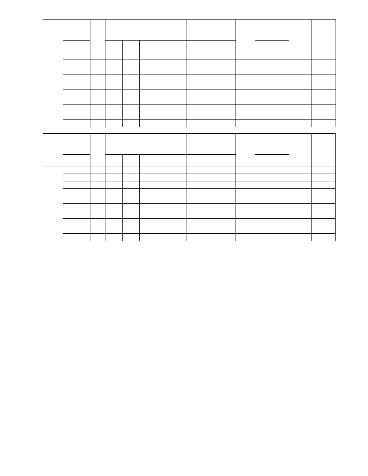
Indoor unit
capacity
Total
Heating Capacity (kW) Input Power (W)
COP
W/W
HSPF
Current,
230V
(A)
Moisture
Removal
Volume
(l/h)
Heating
Room A Room
B
Total
min ~ max
Rating
min ~ max
Region
IV
Region
V
2 Room
1.6 + 1.6 3.2 2.350 2.350 4.70
2.11 ~ 5.64
1450
400 ~ 1770
3.24 9.50 8.50 6.5
1.6 + 2.0 3.6 2.329 2.911 5.24 2.11 ~ 6.29 1600 400 ~ 2020 3.26 9.50 8.50 7.2
1.6 + 2.5 4.1 2.181 3.409 5.59 2.11 ~ 6.71 1740 400 ~ 2170 3.20 9.50 8.50 7.8
1.6 + 3.2 4.8 1.980 3.960 5.94 2.11 ~ 7.13 1800 400 ~ 2340 3.30 9.50 8.50 8.0
2.0 + 2.0 4.0 2.890 2.890 5.78 2.11 ~ 6.94 1770 400 ~ 2260 3.26 9.50 8.50 7.8
2.0 + 2.5 4.5 2.640 3.300 5.94 2.11 ~ 7.13 1870 400 ~ 2360 3.16 9.50 8.50 8.3
2.0 + 3.2 5.2 2.285 3.655 5.94
2.11 ~ 7.20
1750
400 ~ 2180
3.38 9.50 8.50 7.8
2.5 + 2.5 5.0 2.970 2.970 5.94 2.11 ~ 7.20 1750 400 ~ 2180 3.38 9.50 8.50 7.8
2.5 + 3.2 5.7 2.605 3.335 5.94 2.11 ~ 7.20 1750 400 ~ 2180 3.38 9.50 8.50 7.8
3.2 + 3.2 6.4 2.970 2.970 5.94 2.11 ~ 7.20 1750 400 ~ 2180 3.38 9.50 8.50 7.8
Indoor unit
capacity
Total
Heating Capacity (BTU/hr) Input Power (W)
COP
Btu/h.W
HSPF
Current,
230V
(A)
Moisture
Removal
Volume
(l/h)
Heating
Room A Room
B
Total min ~ max Rating min ~ max
Region
IV
Region
V
2 Room
1.6 + 1.6 3.2 8000 8000 16000 7200 ~ 19200 1450 400 ~ 1770 11.00 9.50 8.50 6.5
1.6 + 2.0 3.6 7956 9944 17900 7200 ~ 21400 1600 400 ~ 2020 11.15 9.50 8.50 7.2
1.6 + 2.5 4.1 7454 11646 19100 7200 ~ 22800 1740 400 ~ 2170 10.95 9.50 8.50 7.8
1.6 + 3.2 4.8 6733 13467 20200 7200 ~ 24400 1800 400 ~ 2340 11.20 9.50 8.50 8.0
2.0 + 2.0 4.0 9850 9850 19700
7200 ~ 23600
1770
400 ~ 2260
11.10 9.50 8.50 7.8
2.0 + 2.5 4.5 8978 11222 20200 7200 ~ 24400 1870 400 ~ 2360 10.80 9.50 8.50 8.3
2.0 + 3.2 5.2 7769 12431 20200 7200 ~ 24600 1750 400 ~ 2180 11.50 9.50 8.50 7.8
2.5 + 2.5 5.0 10100 10100 20200 7200 ~ 24600 1750 400 ~ 2180 11.50 9.50 8.50 7.8
2.5 + 3.2 5.7 8860 11340 20200 7200 ~ 24600 1750 400 ~ 2180 11.50 9.50 8.50 7.8
3.2 + 3.2 6.4 10100 10100 20200 7200 ~ 24600 1750 400 ~ 2180 11.50 9.50 8.50 7.8
Specifications are subject to change without notice for further improvement.
8
Indoor unit
capacity
(Ducted
Indoor)
Total
Cooling Capacity (kW) Input Power (W)
EER
W/W
SEER
Current,
230V (A)
Moisture
Removal
Volume (l/h)
Cooling
Room A Room
B
Total
min ~ max
Rating
min ~ max
2 Room
1.6 + 1.6 3.2 1.620 1.620 3.24 2.10 ~ 3.89 770 360 ~ 960 4.20 19.00 3.6 0.3 + 0.3
1.6 + 2.0 3.6 1.613 2.017 3.63 2.10 ~ 4.36 860 360 ~ 1110 4.22 19.00 4.0 0.3 + 0.4
1.6 + 2.5 4.1 1.616 2.524 4.14 2.10 ~ 4.97 1030 360 ~ 1370 4.02 19.00 4.7 0.3 + 0.5
1.6 + 3.2 4.8 1.610 3.220 4.83
2.10 ~ 5.80
1290
360 ~ 1680
3.74 19.00 5.8 0.3 + 0.6
2.0 + 2.0 4.0 2.010 2.010 4.02 2.10 ~ 4.82 980 360 ~ 1310 4.10 19.00 4.5 0.4 + 0.4
2.0 + 2.5 4.5 2.013 2.517 4.53 2.10 ~ 5.44 1210 360 ~ 1580 3.74 19.00 5.5 0.4 + 0.5
2.0 + 3.2 5.2 1.881 3.009 4.89 2.10 ~ 5.86 1330 360 ~ 1690 3.68 19.00 6.0 0.4 + 0.6
2.5 + 2.5 5.0 2.445 2.445 4.89
2.10 ~ 5.86
1330
360 ~ 1690
3.68 19.00 6.0 0.5 + 0.5
2.5 + 3.2 5.7 2.145 2.745 4.89 2.10 ~ 5.86 1330 360 ~ 1690 3.68 19.00 6.0 0.5 + 0.6
3.2 + 3.2 6.4 2.445 2.445 4.89 2.10 ~ 5.86 1330 360 ~ 1690 3.68 19.00 6.0 0.6 + 0.6
Indoor unit
capacity
(Ducted
Indoor)
Total
Cooling Capacity (BTU/hr) Input Power (W)
EER
Btu/h.W
SEER
Current,
230V (A)
Moisture
Removal
Volume (l/h)
Cooling
Room A Room
B
Total min ~ max Rating min ~ max
2 Room
1.6 + 1.6 3.2 5500 5500 11000 7200 ~ 13300 770 360 ~ 960
14.25
19.00 3.6 0.3 + 0.3
1.6 + 2.0 3.6 5511 6889 12400
7200 ~ 14900
860
360 ~ 1110
14.40
19.00 4.0 0.3 + 0.4
1.6 + 2.5 4.1 5502 8598 14100
7200 ~ 16900
1030
360 ~ 1370
13.65
19.00 4.7 0.3 + 0.5
1.6 + 3.2 4.8 5500 11000 16500 7200 ~ 19800 1290 360 ~ 1680
12.75
19.00 5.8 0.3 + 0.6
2.0 + 2.0 4.0 6850 6850 13700 7200 ~ 16400 980 360 ~ 1310
13.95
19.00 4.5 0.4 + 0.4
2.0 + 2.5 4.5 6844 8556 15400 7200 ~ 18500 1210 360 ~ 1580
12.70
19.00 5.5 0.4 + 0.5
2.0 + 3.2 5.2 6423 10277 16700 7200 ~ 20000 1330 360 ~ 1690
12.55
19.00 6.0 0.4 + 0.6
2.5 + 2.5 5.0 8350 8350 16700
7200 ~ 20000
1330
360 ~ 1690
12.55
19.00 6.0 0.5 + 0.5
2.5 + 3.2 5.7 7325 9375 16700
7200 ~ 20000
1330
360 ~ 1690
12.55
19.00 6.0 0.5 + 0.6
3.2 + 3.2 6.4 8350 8350 16700 7200 ~ 20000 1330 360 ~ 1690
12.55
19.00 6.0 0.6 + 0.6
Specifications are subject to change without notice for further improvement.
9
Indoor unit
capacity
(Ducted
Indoor)
Total
Heating Capacity (kW) Input Power (W)
COP
W/W
HSPF
Current,
230V
(A)
Moisture
Removal
Volume
(l/h)
Heating
Room A Room
B
Total
min ~ max
Rating
min ~ max
Region
IV
Region
V
2 Room
1.6 + 1.6 3.2 2.350 2.350 4.70
2.11 ~ 5.64
1450
400 ~ 1770
3.24 9.00 8.20 6.5
1.6 + 2.0 3.6 2.329 2.911 5.24 2.11 ~ 6.29 1600 400 ~ 2020 3.26 9.00 8.20 7.2
1.6 + 2.5 4.1 2.181 3.409 5.59 2.11 ~ 6.71 1740 400 ~ 2170 3.20 9.00 8.20 7.8
1.6 + 3.2 4.8 1.980 3.960 5.94 2.11 ~ 7.13 1800 400 ~ 2340 3.30 9.00 8.20 8.0
2.0 + 2.0 4.0 2.890 2.890 5.78 2.11 ~ 6.94 1770 400 ~ 2260 3.26 9.00 8.20 7.8
2.0 + 2.5 4.5 2.640 3.300 5.94 2.11 ~ 7.13 1870 400 ~ 2360 3.16 9.00 8.20 8.3
2.0 + 3.2 5.2 2.285 3.655 5.94
2.11 ~ 7.20
1750
400 ~ 2180
3.38 9.00 8.20 7.8
2.5 + 2.5 5.0 2.970 2.970 5.94 2.11 ~ 7.20 1750 400 ~ 2180 3.38 9.00 8.20 7.8
2.5 + 3.2 5.7 2.605 3.335 5.94 2.11 ~ 7.20 1750 400 ~ 2180 3.38 9.00 8.20 7.8
3.2 + 3.2 6.4 2.970 2.970 5.94 2.11 ~ 7.20 1750 400 ~ 2180 3.38 9.00 8.20 7.8
Indoor unit
capacity
(Ducted
Indoor)
Total
Heating Capacity (BTU/hr) Input Power (W)
COP
Btu/h.W
HSPF
Current,
230V
(A)
Moisture
Removal
Volume
(l/h)
Heating
Room A Room
B
Total
min ~ max
Rating
min ~ max
Region
IV
Region
V
2 Room
1.6 + 1.6 3.2 8000 8000 16000
7200 ~ 19200
1450
400 ~ 1770
11.00 9.00 8.20 6.5
1.6 + 2.0 3.6 7956 9944 17900
7200 ~ 21400
1600
400 ~ 2020
11.15 9.00 8.20 7.2
1.6 + 2.5 4.1 7454 11646 19100 7200 ~ 22800 1740 400 ~ 2170 10.95 9.00 8.20 7.8
1.6 + 3.2 4.8 6733 13467 20200 7200 ~ 24400 1800 400 ~ 2340 11.20 9.00 8.20 8.0
2.0 + 2.0 4.0 9850 9850 19700 7200 ~ 23600 1770 400 ~ 2260 11.10 9.00 8.20 7.8
2.0 + 2.5 4.5 8978 11222 20200 7200 ~ 24400 1870 400 ~ 2360 10.80 9.00 8.20 8.3
2.0 + 3.2 5.2 7769 12431 20200
7200 ~ 24600
1750
400 ~ 2180
11.50 9.00 8.20 7.8
2.5 + 2.5 5.0 10100 10100 20200
7200 ~ 24600
1750
400 ~ 2180
11.50 9.00 8.20 7.8
2.5 + 3.2 5.7 8860 11340 20200 7200 ~ 24600 1750 400 ~ 2180 11.50 9.00 8.20 7.8
3.2 + 3.2 6.4 10100 10100 20200 7200 ~ 24600 1750 400 ~ 2180 11.50 9.00 8.20 7.8
Specifications are subject to change without notice for further improvement.
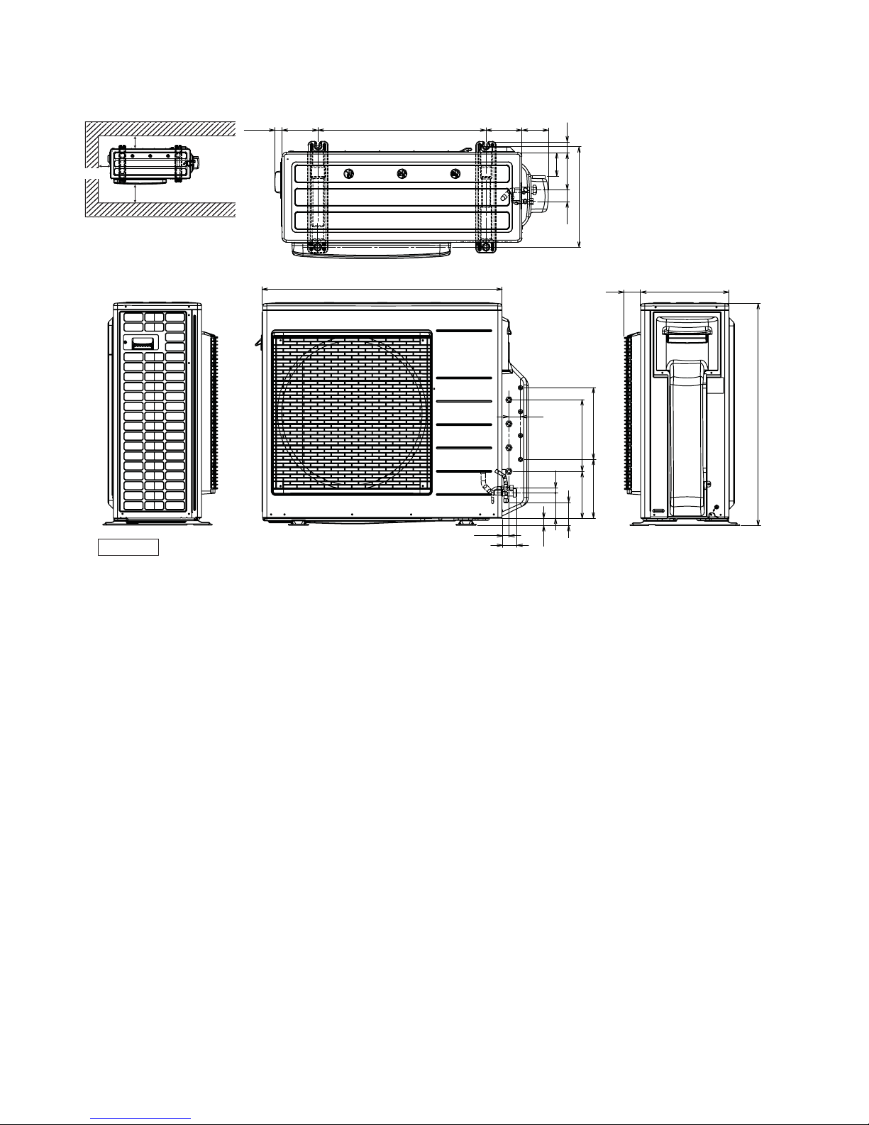
10
3. Dimensions
<Top View>
Space necessary for
installation
<Front View>
<Side View>
<Side View>
1-3/32
39-3/38
3-7/8
3-7/8
24-1/8
Anchor Bolt Pitch
14-13/64 x 24-1/8
34-15/32
5-5/32 3-3/4
1-1/2
5-7/321-5/8
14-3/6
3-9/32
(5-5/32)
1-21/32
3-3/8 x 3 = 10-1/8
(8-9/32)
(6-9/16)
(63/64)
(3-3/16)
3-19/32
43/64
3-3/8 x 3 = 10-1/8
2-5/16 12-5/8
31-5/16
2-1/2
15/16
Unit: inch
11
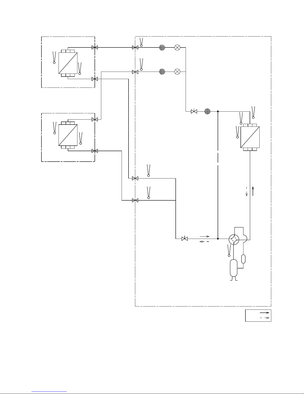
4. Refrigeration Cycle Diagram
PIPE
TEMP.
SENSOR
PIPE
TEMP.
SENSOR
PIPE TEMP.
SENSOR (DEF)
COOLING
HEATING
CONDENSOR
DISCH.
TEMP.
SENSOR
INTAKE
TEMP.
SENSOR
HEAT
EXCHANGER
(CONDENSOR)
INTAKE
TEMP.
SENSOR
PIPE
TEMP.
SENSOR
HEAT
EXCHANGER
(EVAPORATOR)
INTAKE
TEMP.
SENSOR
PIPE
TEMP.
SENSOR
HEAT
EXCHANGER
(EVAPORATOR)
PIPE
TEMP.
SENSOR
PIPE
TEMP.
SENSOR
EXPANSION
VALVE A
STRAINER
EXPANSION
VALV E B
STRAINER
STRAINER3- WAY VALVE
3- WAY VALVE
COMPRESSOR
TEMP.
SENSOR
COMPRESSOR
LIQUID SIDE
LIQUID SIDE
GAS SIDE
3- WAY VALVE
3- WAY VALVE
3- WAY VALVE
GAS SIDE
3- WAY VALVE
INDOOR B
INDOOR A
OUTDOOR
12
5. Block Diagram
123
1
N
L
POWER
SUPPLY
TO INDOOR UNIT ATO INDOOR UNIT B
2
3
FUSE
NOISE
FILTER
SC
REACTOR
L
FUSE
FM
COMP
13
6. Wiring Connection Diagram
Resistance of Compressor Windings
CONNECTION 5KD184XAB21 ()
U - V
U - W
V - W
0.720
0.726
0.708
REMARKS
BLU: BLUE
BLK: BLACK
WHT: WHITE
RED: RED
YLW: YELLOW
GRY: GRAY
GRN: GREEN
Y/G: YELLOW/GREEN
123
123
L1
L2
GRN
GRN
CORE
FG1
CORE
CORE
TERMINAL BOARD
POWER SUPPLY
TO INDOOR UNIT ATO INDOOR UNIT B
TERMINAL BOARD
CORE
CORE
M M
FM
BLK
BLK
WHT
WHT
Y/G
BLK
BLU
RED
WHT
FG2
CN-WHT
WHT
BLK
WHT
WHT
WHT
WHT
WHT
WHT
WHT
WHT
WHT
CN-BLK
WHITE
ACN1
BLACK
ACL1
CN-COM
1
3
5
7
9
FUSE 401
30A 250V
ELECTRONIC CONTROLLER
(SUB)
ELECTRONIC CONTROLLER
(DISPLAY)
POWER SAVE
JP1
COOL ONLY
1
1
1
1
7
6
8
14
7
1
PRIORITY MODE
PUMP DOWN
OPERATION TEST
WIRING CHECK
GROUND PLATE
Y/G
CORE
YELLOW (W)
RED (U)BLUE (V)
(TRADEMARK)
COMP. TERMINAL
CORE
CN-DATA
WHITE
CN-DATA
WHITE
1
9
1
9
WHT
WHT
WHT
WHT
WHT
WHT
WHT
WHT
WHT
WHT
WHT
WHT
WHT
WHT
WHT
WHT
WHT
WHT
WHT
WHT
WHT
CN-DISP 1
WHITE
CN-NMODE 1
WHITE
CN-DISP 1
WHITE
CN-DISP 2
WHITE
CN-NMODE
YELLOW
ELECTRO-
MAGNETIC
COIL
(4 WAY VALVE)
CRANK
CASE
HEATER
ELECTRO-
MAGNETIC COIL
(EXPAND VALVE)
ELECTRO-
MAGNETIC COIL
(EXPAND VALVE)
SENSOR
COMPLETE
DIS.T.TEMP.SENSOR
(THERMISTOR)
PIPE TEMP.SENSOR (DEF)
(THERMISTOR)
SENSOR
COMPLETE
SENSOR
COMPLETE
COND.TEMP.SENSOR
(THERMISTOR)
OUTLET TEMP.SENSOR
(THERMISTOR)
GAS PIPE
SENSOR A
LIQUID PIPE
SENSOR A
LIQUID PIPE
SENSOR B
GAS PIPE
SENSOR B
SENSOR COMPLETE
SENSOR COMPLETE
HIGH PRESSURE SW.
FAN MOTOR
RED
RED
COMPRESSOR
BLK
BLK
GRY
GRY
REACTOR
REACTOR
CONNECTOR
WHITE
4
4
1
11
33
RED
BLU
YLW
RED
BLU
YLW
CORE
1
GRY
AC-WHT
AC-BLK
GRY BLK BLK
FUSE1
T 3.15A
L 250V
FUSE2
T 2.5A
L 250V
RY-PWR
RY-AC
PTC1
PTC2
DB2
DB1
L
DB3
CT400
RY-C
T1
L1-I L2-I L2-O L1-O
L
L
LL
L
L
P
N
U
V
W
CN-FM1
WHITE
1
1
1
1
1411161
1133
824
11
10
2
7
CN-PSW1
BLUE
CN-TH3
WHITE
CN-TH4
WHITE
CN-TH1
WHITE
CN-TH2
YELLOW
CN-DIS
WHITE
CN-EV2
YELLOW
CN-EV1
WHITE
CN-HT
BLACK
CN-HOT
BLUE
CR3
RY-HOT
RY-HT
ELECTRONIC CONTROLLER
(MAIN)
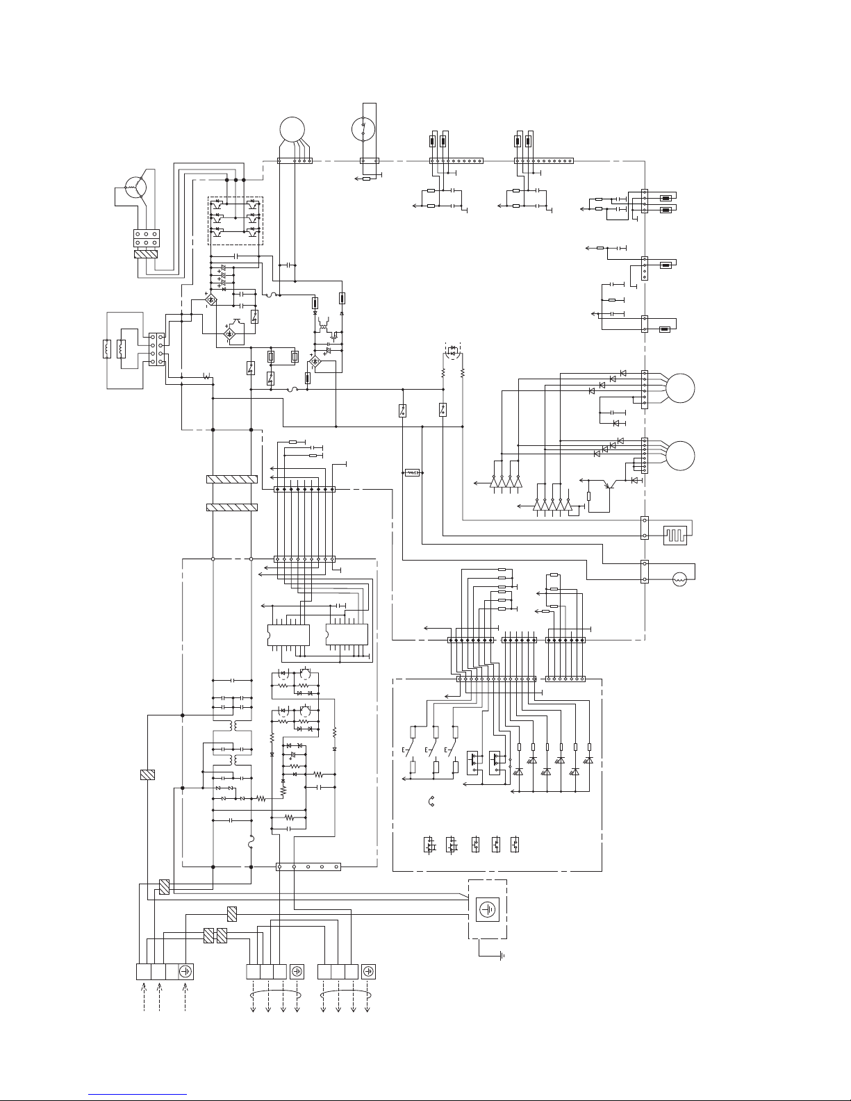
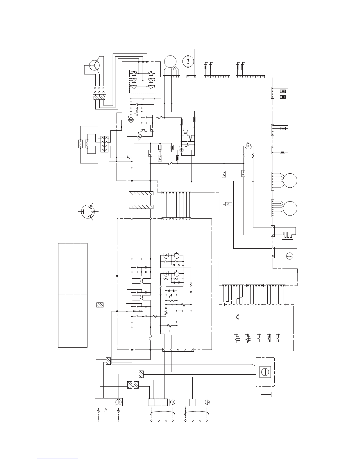
14
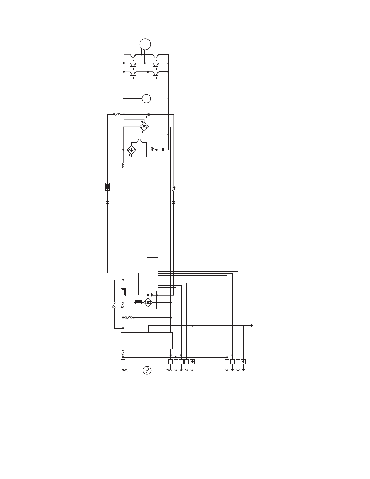
7. Electronic Circuit Diagram
123
123
L1
L2
GRN
GRN
CORE
FG1
CORE
CORE
TERMINAL BOARD
POWER SUPPLY
TO INDOOR UNIT ATO INDOOR UNIT B
TERMINAL BOARD
CORE
CORE
M M
FM
BLK
BLK
WHT
WHT
Y/G
BLK
BLU
RED
WHT
FG2
CN-WHT
WHT
BLK
WHT
WHT
WHT
WHT
WHT
WHT
WHT
WHT
WHT
CN-BLK
WHITE
ACN1
BLACK
ACL1
CN-COM
13579
FUSE 401
30A 250V
ELECTRONIC CONTROLLER
(SUB)
GROUND PLATE
Y/G
CORE
CORE
CN-DATA
WHITE
CN-DATA
WHITE
1
9
1
9
ELECTRONIC CONTROLLER
(DISPLAY)
POWER SAVE
JP1
COOL ONLY
1
1
1
1
7
6
8
14
7
1
PRIORITY MODE
PUMP DOWN
OPERATION TEST
WIRING CHECK
WHT
WHT
WHT
WHT
WHT
WHT
WHT
WHT
WHT
WHT
WHT
WHT
WHT
WHT
WHT
WHT
WHT
WHT
WHT
WHT
WHT
CN-DISP 1
WHITE
CN-NMODE 1
WHITE
CN-DISP 1
WHITE
CN-DISP 2
WHITE
CN-NMODE
YELLOW
ELECTRO-
MAGNETIC
COIL
(4 WAY VALVE)
CRANK
CASE
HEATER
ELECTRO-
MAGNETIC COIL
(EXPAND VALVE)
ELECTRO-
MAGNETIC COIL
(EXPAND VALVE)
SENSOR
COMPLETE
DIS.T.TEMP.SENSOR
(THERMISTOR)
PIPE TEMP.SENSOR (DEF)
(THERMISTOR)
SENSOR
COMPLETE
SENSOR
COMPLETE
COND.TEMP.SENSOR
(THERMISTOR)
OUTLET TEMP.SENSOR
(THERMISTOR)
GAS PIPE
SENSOR A
LIQUID PIPE
SENSOR A
LIQUID PIPE
SENSOR B
GAS PIPE
SENSOR B
SENSOR COMPLETE
SENSOR COMPLETE
HIGH PRESSURE SW.
FAN MOTOR
RED
RED
COMPRESSOR
BLK
BLK
GRY
GRY
REACTOR
REACTOR
CONNECTOR
WHITE
4
4
1
11
33
RED
BLU
YLW
RED
BLU
YLW
CORE
1
GRY
AC-WHT
AC-BLK
GRY BLK BLK
FUSE1
T 3.15A
L 250V
FUSE2
T 2.5A
L 250V
RY-PWR
RY-AC
PTC1
PTC2
DB2
DB1
L
DB3
CT400
RY-C
T1
L1-I L2-I L2-O L1-O
L
L
LL
L
L
P
N
U
V
W
CN-FM1
WHITE
1
1
1
1
1411161
1133
824
11
10
2
7
CN-PSW1
BLUE
CN-TH3
WHITE
CN-TH4
WHITE
CN-TH1
WHITE
CN-TH2
YELLOW
CN-DIS
WHITE
CN-EV2
YELLOW
CN-EV1
WHITE
CN-HT
BLACK
CN-HOT
BLUE
CR3
RY-HOT
RY-HT
ELECTRONIC CONTROLLER
(MAIN)
5V
R100
15.0k
1%
R101
7.50k
1%
C46
1u
6.3V
C45
1u
6.3V
5V
C47
1u
6.3V
R102
4.99k
1%
C209
1u
6.3V
KB
5V
C48
1u
6.3V
R103
7.50k
1%
5V
C239
1u
6.3V
C240
1u
6.3V
R342
15.8k
1%
R341
15.8k
1%
5V
C232
1u
6.3V
C241
1u
6.3V
R338
15.8k
1%
R333
15.8k
1%
13V
R138
5.6k
D64
D63
D62
D34
KB
C218
0.047u
25V
D61
D60
D59
D58
D57
13V
D33
Q25
b
c
e
R365
10k
2SB1188
13V
13V
IC8
IC8
IC8
IC8
VCC
VCC
GND
1
9
B1HBGFF00007
B1HBGFF00007
234
161514
13
IC15
116
IC15
215
IC15
314
IC15
413
IC15
710
8
9
5V
R256
10k
R147
10k
R146
10k
R386
10k
5V
5V
R309 1.2k
GREEN
LED6
GREEN
LED5
GREEN
LED3
GREEN
LED1
GREEN
LED4
GREEN
LED2
R308 1.2k
R307 1.2k
R306 1.2k
R305 1.2k
R304 1.2k
5V
JP1
SW4
SW5
ON OFF
ON OFF
123
123
5V
1
2
3
4
1
2
3
4
1
2
3
4
SW3
SW2
SW1
5V
5V
R373 10k
R374 10k
R375 10k
R370 10k
R371 10k
R372 10k
5V13V
C276
1000p
R388
47k
R253
10k
5V
13V
VDD
2X
1X
X-COM
0X
3X
A
B
0Y2YY-C O M3Y1Y
INH
VEE
VSS
1234567
8
16151413121110
9
5V
KB
C212
1u
16V
IC17
TC4052B
1234567
8
16151413121110
9
IC18
TC4052B
VDD
2X
1X
X-COM
0X
3X
A
B
0Y2YY-C O M3Y1Y
INH
VEE
VSS
15
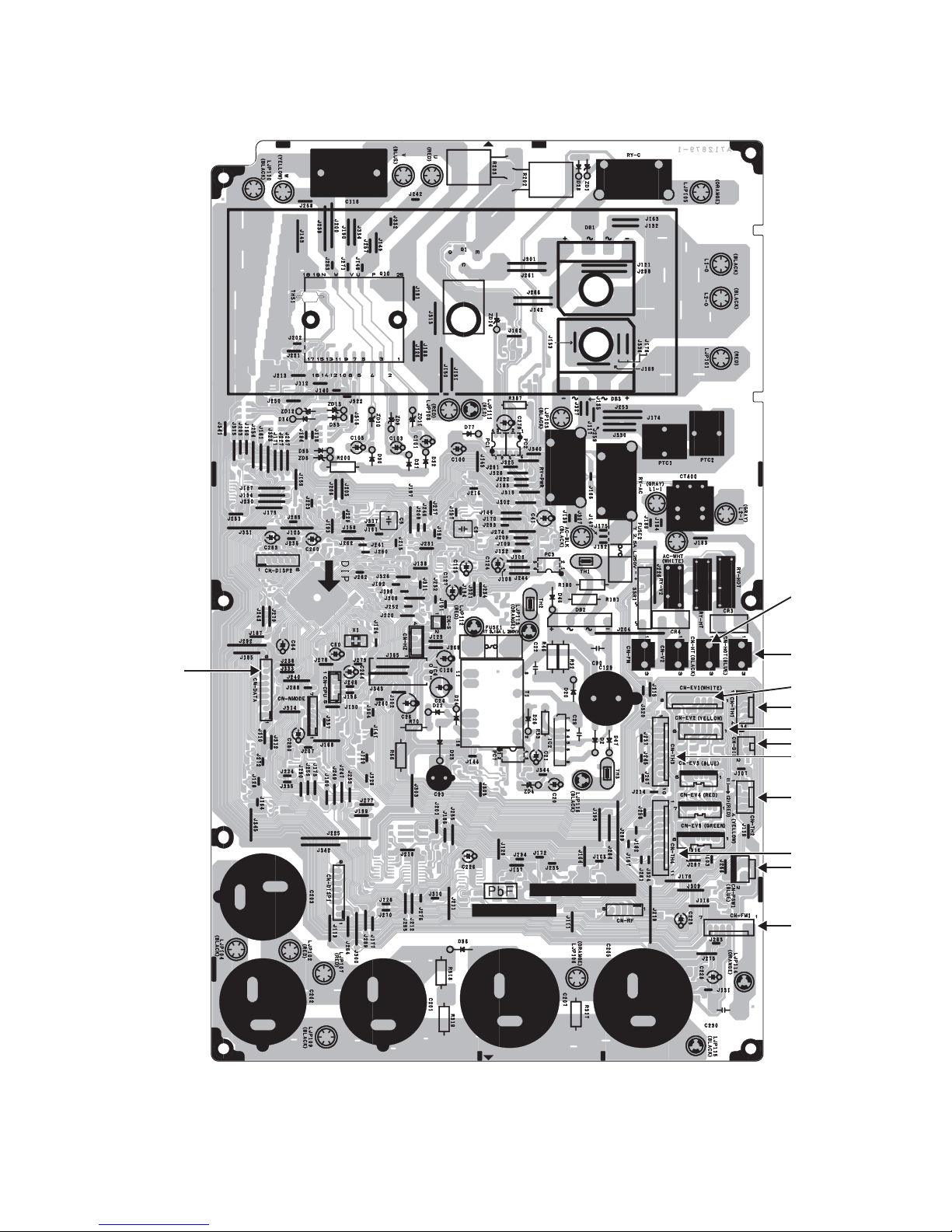
8. Printed Circuit Board
8.1 Main Printed Circuit Board
CN-TH1
CN-HOT
CN- DATA
CN-EV1
CN-HT
CN-EV2
CN-DIS
CN-TH3
CN-TH2
CN-TH4
CN-PSW1
CN-FM1
 Loading...