

Page 1
Order No: PAPAMY1604017CE
Installation Manual
Outdoor Unit
CU-2E18SBU
Please file and use this manual together with the service manual for Model No. CS-ME5RKUA CS-ME7RKUA, CS-E9RKUA
CS-E12RKUA, CS-ME9SB4U, CS-E12RB4UW, CS-ME5SD3UA CS-ME7SD3UA, CS-E9SD3UAW CS-E12SD3UAW, Order No.
PAPAMY1503085CE, PAPAMY1501049CE, PAPAMY1604059CE, PAPAMY1503095CE, PAPAMY1604056CE,
PAPAMY1604052CE.
WARNING
This service information is designed for experienced repair technicians only and is not designed for use by the general public.
It does not contain warnings or cautions to advise non-technical individuals of potential dangers in attempting to service a product.
Products powered by electricity should be serviced or repaired only by experienced professional technicians. Any attempt to
service or repair the product or products dealt with in this service information by anyone else could result in serious injury or death.
PRECAUTION OF LOW TEMPERATURE
In order to avoid frostbite, be assured of no refrigerant leakage during the installation or repairing of refrigerant circuit.
© Panasonic Corporation 2016
Page 2
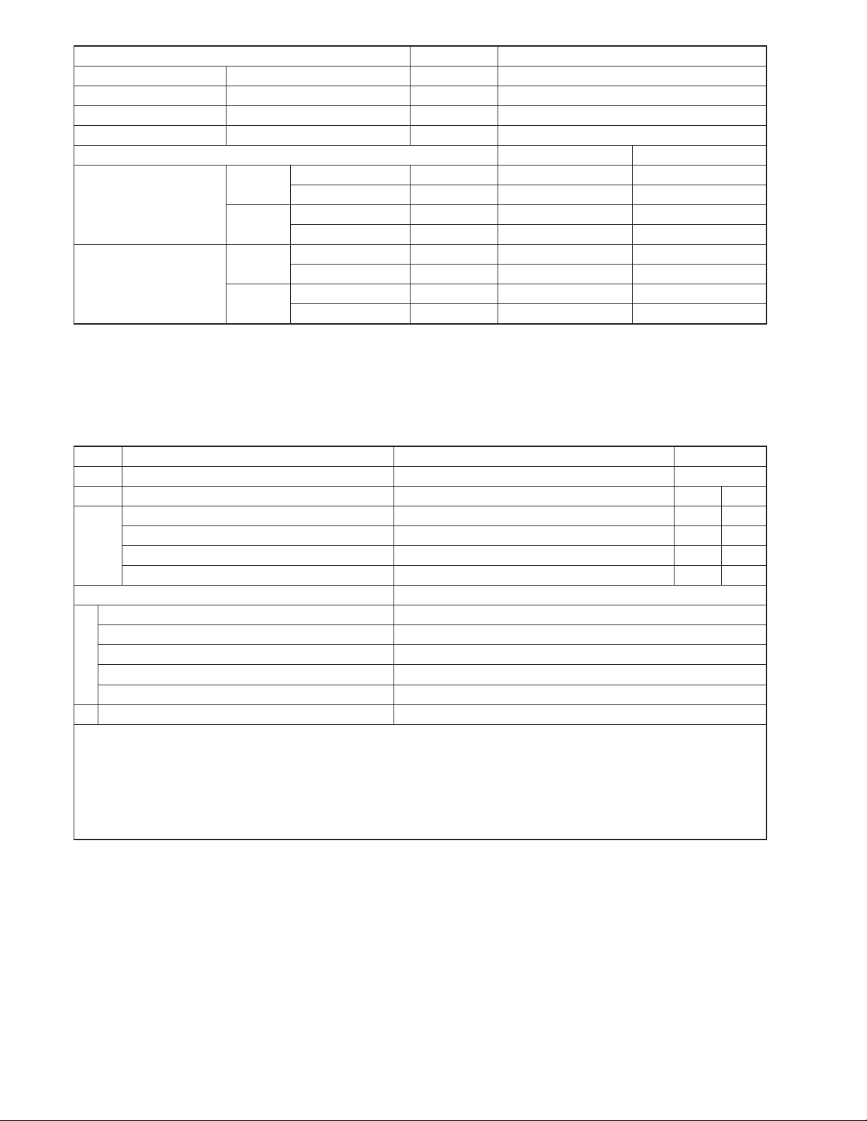
Item Unit OUTDOOR UNIT
Air Volume High m3/min (ft3/min) 41.0 (1447)
Refrigerant Control Device Expansion Valve
Refrigerant Oil cm3 FV50S (900)
Refrigerant (R410A) g (oz) 2.23k (78.7)
Dry Bulb Wet Bulb
Cooling
Indoor Operation Range
Heating
Cooling
Outdoor Operation Range
Heating
Maximum °C (°F) 32 (89.6) 23 (73.4)
Minimum °C (°F) 16 (60.8) 11 (51.8)
Maximum °C (°F) 30 (86.0) —
Minimum °C (°F) 16 (60.8) —
Maximum °C (°F) 46 (114.8) 26 (78.8)
Minimum °C (°F) -10 (14.0) — / —
Maximum °C (°F) 24 (75.2) 18 (64.4)
Minimum °C (°F) -15 (5.0) -16 (3.2)
Note
x Specifications are subject to change without notice for further improvement.
x Multi split combination possibility:
o A single outdoor unit enables air conditioning of up to two separate rooms for CU-2E18SBU.
Outdoor Unit
CU-2E18SBU
A B
1.6 kW CS-ME5RKUA, CS-ME5SD3UA
2.0 kW CS-ME7RKUA, CS-ME7SD3UA
Wall
Capacity range of connectable indoor units From 3.2 kW to 6.4 kW
1 room maximum pipe length (m (ft)) 25 (82.0)
Allowable elevation (m (ft)) 15 (49.2)
Total allowable pipe length (m (ft)) 50 (164.0)
Total pipe length for maximum chargeless length (m (ft)) 20 (65.6)
Piping Length
Additional gas amount over chargeless length (g/m (oz/ft)) 20 (0.2)
Remarks for CU-2E18SBU
1. At least two indoor units must be connected.
2. The total nominal cooling capacity of indoor units that will be connected to outdoor unit must be within connectable capacity range of
indoor unit.
(as shown in the table above)
Example: The indoor units’ combination below is possible to connect to CU-2E18SBU. (Total nominal capacity of indoor units is between
3.2 kW to 6.4 kW)
1) Two CS-E9RKUAW only. (Total nominal cooling capacity is 5.0 kW)
2) One CS-E9RKUAW and one CS-E12RKUAW. (Total nominal cooling capacity is 5.7 kW)
x Specifications are subject to change without notice for further improvement.
2.5 kW CS-E9RKUAW, CS-ME9SB4U, CS-E9SD3UAW
3.2 kW CS-E12RKUAW, CS-E12RB4UW, CS-E12SD3UAW
Note: “
• •
• •
• •
• •
•” : Available
6
Page 3
9. Installation Information
9.1 Check Points
49.2 ft max.
82 ft
82 ft
Total maximum pipe length: 164 ft
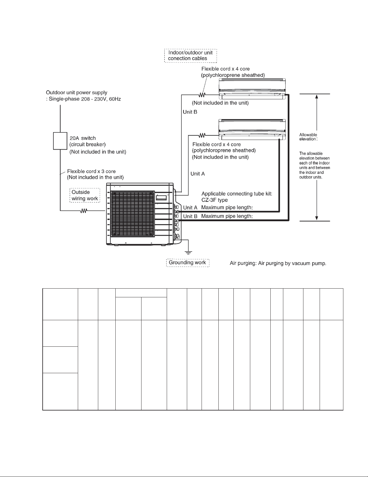
QUICK GUIDE PIPING AND ELECTRICAL SPECIFICATION
Indoor (ID) &
Outdoor (OD)
units: Possible
Combination
Patterns
Outdoor (OD):
CU-2E18SBU
Indoor (ID): 2
UNITS OF CSE9RKUAW
Outdoor (OD):
CU-2E18SBU
Indoor (ID): 2
UNITS OF CSE12RKUAW
Outdoor (OD):
CU-2E18SBU
Indoor (ID): 1
UNIT OF CSE9RKUAW +
1 UNIT OF
CS-E12RKUAW
Capacity
Refrige-
(Btu/h)
16700 R410A
rant
Piping size
Gas Liquid
Ø3/8”
(Ø9.52mm)
Ø1/4”
(Ø6.35mm)
Standard
pipe
length
24.6 ft
Min.
Max.
pipe
Max.
Eleva-
tion
See
Step 1
each ID
from
length
OD to
for
each
ID unit
unit
9.8 ft 82.0 ft 164.0 ft 65.6 ft
Max.
total
length
Min. total
pipe
length
for
additional
gas
Additional
refri-
ge-
rant
0.2
oz / ft
Power
supply
208/230V
60 Hz
MCA 20A
MOP
25A
Power
supply
AWG12 AWFG16
wire
size
OD-ID
connection
wire size
Example:
If total piping length of all installed indoor units is at 68.6 ft, the quantity of additional refrigerant should be 0.6 oz ......
(68.6 - 65.6) ft x 0.2 oz/ft = 0.6 oz.
15
Page 4

10. Installation Instruction
x IMPORTANT
This product has been designed and manufactured to meet ENERGY STAR
matched with appropriate coil components. However, proper refrigerant charge and proper air flow are critical to
achieve rated capacity and efficiency. Installation of this product should follow the manufacturer’s refrigerant charging
and air flow instructions. Failure to confirm proper charge and airflow may reduce energy efficiency and
shorten equipment life.
10.1 Accessories Supplied with Outdoor Unit
x The following parts are supplied as accessories with each outdoor unit.
Check that all accessory parts are present before installing the outdoor unit.
HEAT PUMP-TYPES ONLY
Part name Qty. Diagram Application
®
criteria for energy efficiency when
Drain elbow 1
For connecting the drain pipe
10.2 Cutting and Flaring the Piping
1 Please cut using pipe cutter and then remove the burrs.
2 Remove the burrs by using reamer. If burrs is not removed, gas leakage may be caused.
Turn the piping end down to avoid the metal powder entering the pipe.
3 Please make flare after inserting the flare nut onto the copper pipes.
1. To cut
Point down
2. To remove burrs
Pipe
Reamer
Bar
Clamp handle
3. To fl are
Handle
Yo k e
Core
Red arrow mark
Bar
1
0 –
/32"
(0-0.5 mm)
Copper pipe
When properly fl ared, the internal surface
of the fl are will evenly shine and be of
even thickness. Since the flare part
comes into contact with the connections,
carefully check the fl are fi nish.
Improper fl aring
Inclined Surface
damaged
Cracked Uneven
thickness
16
Page 5

10.3 Select the Best Location
10.3.1 Outdoor Unit
x If an awning is built over the unit to prevent direct
sunlight or rain, be careful that heat radiation from
the condenser is not obstructed.
x There should not be any animal or plant which
could be affected by hot air discharged.
x Keep the spaces indicated by arrows from wall,
ceiling, fence or other obstacles.
x Do not place any obstacles which may cause a
short circuit of the discharged air.
x Recommended installation height for outdoor unit
should be above the seasonal snow level.
Refrigerant piping size
Outdoor Unit CU-2E18**
Liquid - side ø1/4" (ø6.35 mm) thickness 1/32" (t0.8 mm)
Gas - side ø3/8" (ø9.52 mm) thickness 1/32" (t0.8 mm)
Outdoor Unit CU-2E18**
Min. total piping length for additional gas 65.6 ft (20 m)
x If total piping length of all indoor units exceeds the
minimum length listed above, additionally charge
with 0.2 oz (20 g) of refrigerant (R410A) for each
additional feet (meter) of piping.
Allowable piping length
Outdoor Unit CU-2E18***
Allowable piping length of each indoor unit (min. ~ max.) 9.8 ft ~ 82.0 ft (3 m ~ 25 m)
Allowable total piping length of all indoor units 164.0 ft (50 m) or less
Height difference between indoor and outdoor units
Height difference between indoor units
Outdoor unit located on upper side
Outdoor unit located otherwise
Outdoor unit located on upper side
Outdoor unit located otherwise
Outdoor unit located
on upper side
Outdoor Unit Installation Diagram
x This illustration is for explanation purposes only.
* Note:
Respective indoor unit installation procedure shall
refer to instruction manual provided in the indoor
unit packaging.
a
b
c
d
Outdoor unit located
otherwise
Indoor unit
Installation parts you
should purchase (
It is advisable to avoid more
than 2 blockage directions.
For better ventilation &
multiple-outdoor installation,
please consult authorized
dealer/specialist.
Power supply cord (
(Conduit)
Connection cable (
(Conduit)
Additional drain hose (
1
4
" (6.35 mm)
/
Liquid side piping (
3
/8" (9.52 mm)
Gas side piping (
49.2 ft (15 m) or less
24.6 ft (7.5 m) or less
24.6 ft (7.5 m) or less
49.2 ft (15 m) or less
)
)
)
)
)
)
a
c
Outdoor unit
d
Outdoor unit
d
b
b
roodnItinu roodn
I
tinu
17
Outdoor unit
Page 6

Outdoor Unit Installation Guidelines
f
x Where a wall or other obstacle is in the path of outdoor unit’s intake or exhaust airflow, follow the installation
guidelines below.
x For any of the below installation patterns, the wall height on the exhaust side should be 47 1/4" (1200 mm) or
less.
Wall facing one side
More than 3 15/16" (100)
47
1
/4" (1200)
or less
More than
3
" (1000)
39
/
8
Walls facing two side Walls facing three side
More than
15
/16" (100)
3
More than
15
/16" (100)
3
weiv poTweiv ediS
More than
3
/
8
39
" (1000)
More than
13
/
11
16
" (300)
More
than
3
(100)
More than
15
3
" (100)
/
16
15
/16"
More than
3
/8" (1000)
39
Top view
Unit : inch (mm)
10.4 Install the Outdoor Unit
x After selecting the best location, start installation
to Indoor/Outdoor Unit Installation Diagram.
1 Fix the unit on concrete or rigid frame firmly
and horizontally with bolt nut (ø13/32"
(ø10 mm)).
2 When installing on a roof, please consider
strong winds and earthquakes.
3 Please fasten the installation stand firmly with
bolt or nails.
10.5 Connect the Piping
x Remove the control board cover (resin) from the
outdoor unit by loosening three screws.
Connecting the Piping to Outdoor Unit
Decide piping length and then cut by using pipe
cutter.
Remove burrs from cut edge. Make flare after
inserting the flare nut (locate at valve) onto the
copper pipe.
Align center of piping to valves and then tighten
with torque wrench to the specified torque as
stated in the table.
Screws
Control Board Cover (Resin)
Liquid side
Gas side
AB
C
D
Model A B C D
CU-2E18***
24 1/8"
(613 mm)
5 5/32"
(131 mm)
5/8"
(16 mm)
14 3/16"
(360.5 mm)
Do not overtighten, over tightening may cause gas leakage.
Piping size Torque
1/4" (6.35 mm) 13.3 Ibf•ft [18 N•m (1.8 kgf•m)]
3/8" (9.52 mm) 31.0 Ibf•ft [42 N•m (4.3 kgf•m)]
1/2" (12.7 mm) 40.6 Ibf•ft [55 N•m (5.6 kgf•m)]
5/8" (15.88 mm) 47.9 Ibf•ft [65 N•m (6.6 kgf•m)]
3/4" (19.05 mm) 73.8 Ibf•ft [100 N•m (10.2 kgf•m)]
Flare Nut
(Connection Pipe)
Torque Wrench for Flare Nut
Flare Nut
(Connection Pipe)
Female side
Applicable to
Liquid and Gas side o
CS-E9***
CS-E12***
CS-ME5***
CS-ME7***
CS-ME9***
Male side
Screw
Torque Wrench for Flare Nut
Gas Leak Checking
Pressure test to system to 400 PSIG with dry nitrogen, in stages. Thoroughly leak check the system.
If the pressure holds, release the nitrogen and proceed to section 10.7.
18
Page 7

10.6 Evacuation of the Equipment
WHEN INSTALLING AN AIR CONDITIONER, BE SURE TO EVACUATE THE AIR INSIDE THE INDOOR UNIT AND
PIPES in the following procedure.
1 Connect a charging hose with a push pin to
the Low side of a charging set and the service
Indoor Unit
port of the gas side 3-way valve.
2 Connect the micron gauge between vacuum
pump and service port of outdoor units.
3 Turn on the power switch of the vacuum pump
and make sure that connect digital micron
gauge and to pull down to a value of
500 microns.
Indoor Unit
4 To make sure micron gauge a value
500 microns and close the low side valve of
the charging set and turn off the vacuum
pump.
5 Disconnect the vacuum pump house from the
service port of the 3-way valve.
6 Tighten the service port caps of gas side
3-way valve at a torque of 13.3 Ibf•ft (18 N•m)
with a torque wrench.
7 Remove the valve caps of both of the 2-way
Vacuum
pump
valve and 3-way valve. Position both of the
valves to “Open” using a hexagonal wrench
(5/32" (4 mm)).
8 Mount valve caps onto the 2-way valve and
3-way valve.
o Be sure to check for gas leakage.
x If micron gauge value does not descend 500 microns, take the following measures:
- If the leak stops when the piping connections are tightened further, continue working from step 3.
- If the leak does not stop when the connections are retightened, repair location of leak.
- Do not release refrigerant during piping work for installation and reinstallation.
- Take care when handling the liquid refrigerant, it may cause frostbite.
Tube connector
Liquid side
Tube connector
Gas
side
Tube connector
Liquid side
Tube connector
Gas
side
Liquid side 3-way valve
Gas side 3-way valve
Close
Close
Outdoor unit
19
Page 8

10.7 Connect the Cable to the Outdoor Unit
1 Remove Control Board Cover (Metal) by
loosening 2 screws.
2 Remove Valve Cover (Metal) by loosening
2 screws.
3 Remove Plugs.
4 Fix the conduit connectors to the knock out
holes with lock-nuts, then secure them.
5 Connecting wire between indoor unit and
outdoor unit should be UL listed or CSA
approved 4 conductor wires minimum AWG16
in accordance with local electric codes.
6 Wire Connection to the power supply
(208/230V 60Hz) through circuit breaker.
o Connect the UL listed or CSA approved
wires minimum AWG12 to the terminal
board, and connect to other end of the
wires to circuit breaker.
7 Connect the power supply cord and
connecting wires between indoor unit and
outdoor unit according to the diagram as
shown.
Indoor
Unit A
Terminal
1
2
3
208/230V min AWG16
208/230V min AWG16
208/230V min AWG16
Grounding wire min AWG16
Outdoor Unit
Terminal
1
2
Unit A
3
Screws
Valve Cover
Screws
Lock Nuts
(Metal)
Side Panel
To p Pa ne l
Control Board Cover
(Metal)
Connectors
Plugs
Knock Out Holes
Unit A Unit B
Indoor
Unit B
Terminal
1
2
3
208/230V min AWG16
208/230V min AWG16
208/230V min AWG16
Grounding wire min AWG16
1
2
Unit B
3
L1
L2
Disconnect
Switch
Field supply
Grounding wire
Power Supply
Single Phase
208/230V 60Hz
min AWG12
Power Supply
Cord
Indoor & outdoor
connection wire
Indoor
Unit A
8 For wire stripping and connection requirement, refer to the diagram below.
9 Secure the power supply cord and connection cables onto the control board with the holder.
10 Attach the control board cover (metal and resin) and valve cover back to the original position with screw.
WIRE STRIPPING AND CONNECTING REQUIREMENT
Wire stripping
"
16
/
1
" ±
32
(10±1 mm)
/
13
No loose strand when inserted
Indoor/outdoor
connecting
terminal board
7
/32" (5 mm)
or more
(gap between
wires)
Conductor fully
inserted
ACCEPT PROHIBITED PROHIBITED
Conductor over
inserted
Conductor not
fully inserted
This equipment must be properly earthed.
o Earth wire must be Yellow/Green (Y/G) in colour and longer than other AC wires for safety reasons.
Indoor
Unit B
10.8 Heat Insulation
Use a material with good heat-resistant properties as the heat insulation for the
pipes. Be sure to insulate both the gas-side and liquid-side pipes. If the pipes are
not adequately insulated, condensation or water leakages may occur.
20
Liquid-side pipes
Gas-side pipes
Material shall
withstand 248°F
(120°C) or
higher
 Loading...