

Page 1
Order No: PAPAMY1604017CE
Outdoor Unit
CU-2E18SBU
Please file and use this manual together with the service manual for Model No. CS-ME5RKUA CS-ME7RKUA, CS-E9RKUA
CS-E12RKUA, CS-ME9SB4U, CS-E12RB4UW, CS-ME5SD3UA CS-ME7SD3UA, CS-E9SD3UAW CS-E12SD3UAW, Order No.
PAPAMY1503085CE, PAPAMY1501049CE, PAPAMY1604059CE, PAPAMY1503095CE, PAPAMY1604056CE,
PAPAMY1604052CE.
WARNING
This service information is designed for experienced repair technicians only and is not designed for use by the general public.
It does not contain warnings or cautions to advise non-technical individuals of potential dangers in attempting to service a product.
Products powered by electricity should be serviced or repaired only by experienced professional technicians. Any attempt to
service or repair the product or products dealt with in this service information by anyone else could result in serious injury or death.
In order to avoid frostbite, be assured of no refrigerant leakage during the installation or repairing of refrigerant circuit.
PRECAUTION OF LOW TEMPERATURE
© Panasonic Corporation 2016
Page 2

TABLE OF CONTENTS
PAGE PAGE
1. Safety Precautions ............................................. 3
2. Specifications ..................................................... 5
2.1 CU-2E18SBU ............................................... 5
3. Dimensions ......................................................... 8
4. Refrigeration Cycle Diagram ............................. 9
5. Block Diagram .................................................. 10
6. Wiring Connection Diagram ............................ 11
7. Electronic Circuit Diagram .............................. 12
8. Printed Circuit Board ....................................... 13
8.1 Main Printed Circuit Board ......................... 13
8.2 Noise Filter Printed Circuit Board ............... 14
8.3 Display Printed Circuit Board ..................... 14
13.16 Compressor Discharge High Pressure
Protection Control .......................................27
14. Servicing Mode .................................................28
14.1 CU-2E18SBU .............................................28
15. Troubleshooting Guide ....................................30
15.1 Self Diagnosis Function ..............................30
16. Disassembly and Assembly Instructions ......33
16.1 Outdoor Unit Removal Procedure ..............33
17. Technical Data ..................................................36
17.1 Cool Mode Performance Data ....................36
17.2 Heat Mode Performance Data ....................38
18. Service Data ......................................................40
9. Installation Information .................................... 15
9.1 Check Points .............................................. 15
10. Installation Instruction ..................................... 16
10.1 Accessories Supplied with Outdoor
Unit ............................................................. 16
10.2 Cutting and Flaring the Piping .................... 16
10.3 Select the Best Location ............................. 17
10.4 Install the Outdoor Unit ............................... 18
10.5 Connect the Piping ..................................... 18
10.6 Evacuation of the Equipment ..................... 19
10.7 Connect the Cable to the Outdoor Unit ...... 20
10.8 Heat Insulation ............................................ 20
11. Operation Control ............................................. 21
11.1 Cooling Operation ....................................... 21
11.2 Heating Operation ...................................... 22
12. Simultaneous Operation Control .................... 23
13. Protection Control ............................................ 24
13.1 Freeze Prevention Control (Cool) ............... 24
13.2 Dew Prevention Control (Cool) ................... 24
13.3 Electronic Parts Temperature Rise
Protection 1 (Cool) ...................................... 24
13.4 Electronic Parts Temperature Rise
Protection 2 (Cool) ...................................... 24
13.5 Cooling Overload Control (Cool) ................ 25
13.6 Heating Overload Control (Heat) ................ 25
13.7 Extreme Low Temperature Compressor
Low Pressure Protection Control (Heat) ..... 25
13.8 Deice Control .............................................. 26
13.9 Time Delay Safety Control (Restart
Control) ....................................................... 26
13.10 30 seconds Force Operation ...................... 26
13.11 Total Current Control .................................. 26
13.12 IPM (power transistor) Protection
Control ........................................................ 26
13.13 Compressor Protection Control (Gas leak
detection control 1) ..................................... 27
13.14 Compressor Protection Control (Gas leak
detection control 2) ..................................... 27
13.15 Valve Close Detection Control ................... 27
18.1 Operation Characteristics ...........................40
19. Exploded View and Replacement Parts
List .....................................................................44
2
Page 3
1. Safety Precautions
Read the following “SAFETY PRECAUTIONS” carefully before installation.
Electrical work must be installed by a licensed electrician. Be sure to use the correct rating of the power plug and main circuit
for the model to be installed.
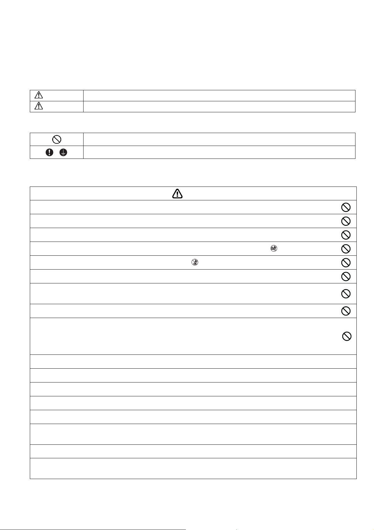
The caution items stated here must be followed because these important contents are related to safety. The meaning of each
indication used is as below. Incorrect installation due to ignoring of the instruction will cause harm or damage, and the
seriousness is classified by the following indications.
WARNING
CAUTION
The items to be followed are classified by the symbols:
Carry out test running to confirm that no abnormality occurs after the installation. Then, explain to user the operation, care
and maintenance as stated in instructions. Please remind the customer to keep the operating instructions for future reference.
This indication shows the possibility of causing death or serious injury.
This indication shows the possibility of causing injury or damage to properties only.
Symbol with white background denotes item that is PROHIBITED from doing.
Symbol with dark background denotes item that must be carried out.
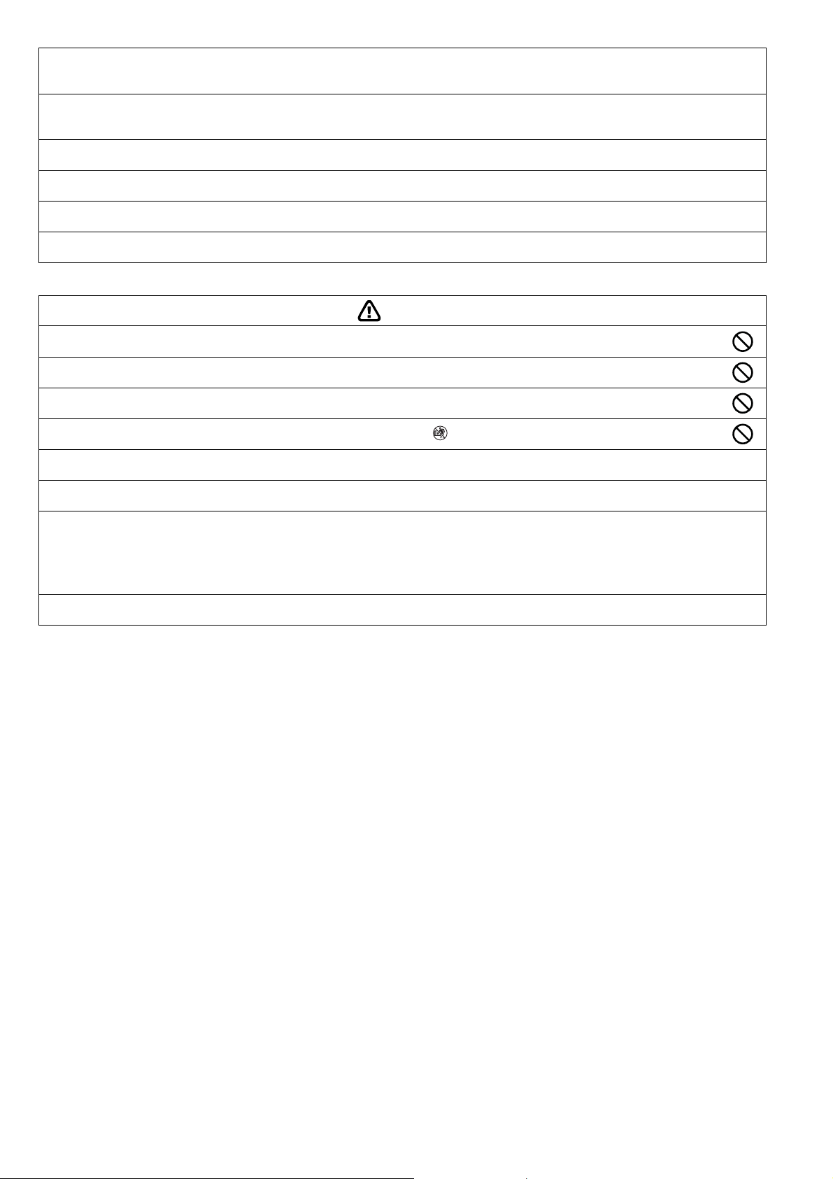
WARNING
Do not install outdoor unit near handrail of veranda. When installing air-conditioner unit on veranda of a high rise building, child
1.
may climb up to outdoor unit and cross over the handrail causing an accident.
Do not use unspecified cord, modified cord, joint cord or extension cord for power supply cord. Do not share the single outlet
2.
with other electrical appliances. Poor contact, poor insulation or over current will cause electrical shock or fire.
3. Do not tie up the power supply cord into a bundle by band. Abnormal temperature rise on power supply cord may happen.
4.
Do not insert your fingers or other objects into the unit, high speed rotating fan may cause injury.
5.
Do not sit or step on the unit, you may fall down accidentally.
6. Keep plastic bag (packaging material) away from small children, it may cling to nose and mouth and prevent breathing.
When installing or relocating air conditioner, do not let any substance other than the specified refrigerant, eg. air etc. mix into
7.
refrigeration cycle (piping). Mixing of air etc will cause abnormal high pressure in refrigeration cycle and result in explosion,
injury etc.
8. Do not add or replace refrigerant other than specified type. It may cause product damage, burst and injury etc.
For R410A model, use piping, flare nut and tools which is specified for R410A refrigerant. Using of existing (R22) piping,
flare nut and tools may cause abnormally high pressure in the refrigerant cycle (piping), and possibly result in explosion and
9.
injury.
Thickness for copper pipes used with R410A must be more than 1/32" (0.8 mm). Never use copper pipes thinner than
1/32" (0.8 mm).
It is desirable that the amount of residual oil less than 0.0008 oz/ft (40 mg/10 m).
Engage authorized dealer or specialist for installation. If installation done by the user is incorrect, it will cause water leakage, electrical
10.
shock or fire.
11. Install according to this installation instructions strictly. If installation is defective, it will cause water leakage, electrical shock or fire.
Use the attached accessories parts and specified parts for installation. Otherwise, it will cause the set to fall, water leakage, fire or
12.
electrical shock.
Install at a strong and firm location which is able to withstand the set’s weight. If the strength is not enough or installation is not properly
13.
done, the set will drop and cause injury.
For installation work, follow all electrical, building, plumbing, local codes, regulations and these installation instructions. If electrical circuit
14.
capacity is not enough or a defect is found in electrical work, it will cause electrical shock or fire.
Do not use spliced wires for indoor/outdoor connection cable. Use the specified indoor/outdoor connection cable, refer to instruction
15.
INDOOR/OUTDOOR UNIT ELECTRICAL WIRING and connect tightly for indoor/outdoor connection. Clamp the cable so that no
external force will have impact on the terminal. If connection or fixing is not perfect, it will cause heat-up or fire at the connection.
Wire routing must be properly arranged so that control board cover is fixed properly. If control board cover is not fixed perfectly, it will
16.
cause fire or electrical shock.
This equipment must installed with an Earth Leakage Circuit Breaker (ELCB) or Ground Fault Current Interrupter (GFCI) or Appliance
17.
Leakage Current Interrupter (ALCI) that has been certified by an NRTL Certified Testing Agency and that is suitable for the voltages and
amperages involved. Otherwise, if may cause electrical shock and fire in case of equipment breakdown.
3
Page 4
During installation, install the refrigerant piping properly before running the compressor. Operation of compressor without fixing
18.
refrigeration piping and valves at opened condition will cause suck-in of air, abnormal high pressure in refrigeration cycle and result in
explosion, injury etc.
During pump down operation, stop the compressor before removing the refrigeration piping. Removal of refrigeration piping while
19.
compressor is operating and valves are opened will cause suck-in of air, abnormal high pressure in refrigeration cycle and result in
explosion, injury etc.
Tighten the flare nut with torque wrench according to specified method. If the flare nut is over-tightened, after a long period, the flare
20.
may break and cause refrigerant gas leakage.
After completion of installation, confirm there is no leakage of refrigerant gas. It may generate toxic gas when the refrigerant comes into
21.
contact with fire.
22. Ventilate if there is refrigerant gas leakage during operation. It may cause toxic gas when the refrigerant comes into contact with fire.
This equipment must be properly earthed. Earth line must not be connected to gas pipe, water pipe, earth of lightning rod and telephone.
23.
Otherwise, it may cause electrical shock in case of equipment breakdown or insulation breakdown.
CAUTION
Do not install the unit at place where leakage of flammable gas may occur. In case gas leaks and accumulates at surrounding
1.
of the unit, it may cause fire.
Do not release refrigerant during piping work for installation, re-installation and during repairing a refrigeration parts. Take care
2.
of the liquid refrigerant, it may cause frostbite.
3. Do not install this appliance in a laundry room or other location where water may drip from the ceiling, etc.
4.
Do not touch the sharp aluminium fin, sharp parts may cause injury.
Carry out drainage piping as mentioned in installation instructions. If drainage is not perfect, water may enter the room and damage the
5.
furniture.
6. Select an installation location which is easy for maintenance.
Power supply connection to the room air conditioner.
Power supply cord shall be UL listed or CSA approved 3 conductor with minimum AWG12 wires.
Power supply point should be in an easily accessible place for power disconnection in case of emergency.
7.
In some countries, permanent connection of this air conditioner to the power supply is prohibited.
Fix power supply connection to a circuit breaker for permanent connection.
Use NRTL approved fuse or circuit breaker (rating refers to name plate) for permanent connection.
Installation work.
8.
It may take two people to carry out the installation work.
4
Page 5
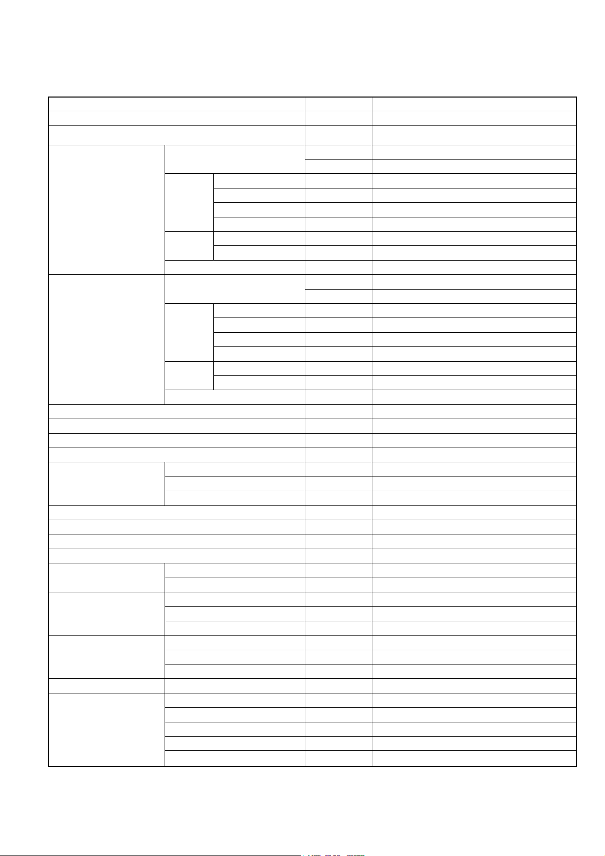
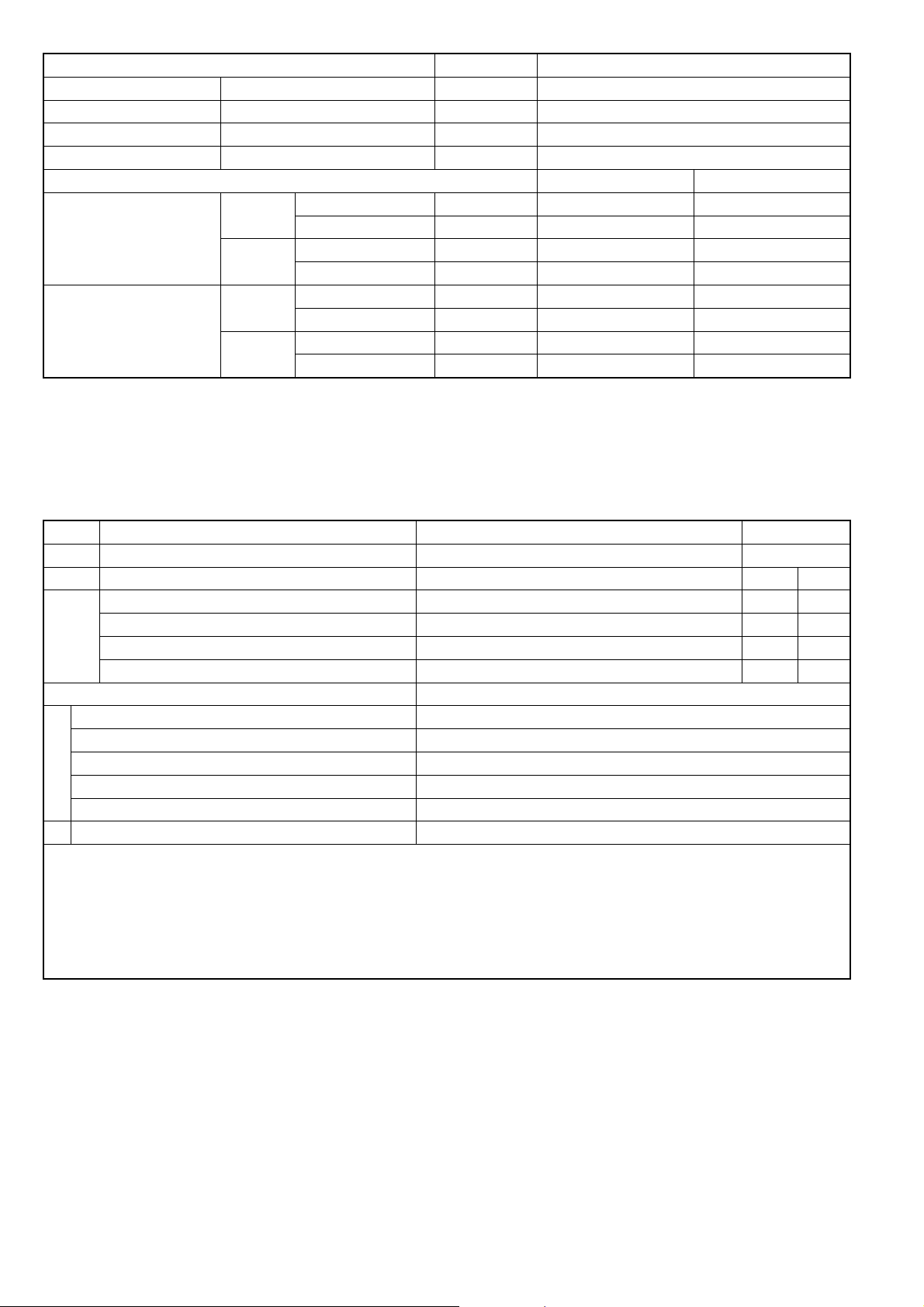
2. Specifications
2.1 CU-2E18SBU
Item Unit OUTDOOR UNIT
Indoor Unit Combination 2.5kW + 2.5kW
Power Source
Capacity
Running Current A 6.6 - 6.0
Electrical
Cooling Operation
Heating Operation
Maximum Current A 13.6
Maximum Input Power W 3.04k
Starting Current A 8.5
Minimum Circuit Ampacity A 20
Dimension
Net Weight kg (lb) 71 (157)
Connection cable 3 + 1 (Earth) ø1.5 mm2
Pipe Length Range (1 room) m (ft) 3 ~ 25 (9.8 ~ 82.0)
Maximum Pipe Length (Total Room) m (ft) 50 (164.0)
Refrigerant Pipe Diameter
Compressor
Air Circulation
Fan Speed High RPM 580
Heat Exchanger
Data
Noise
Power Factor % 97 / 96
Capacity
Electrical
Data
Noise
Power Factor % 99 / 98
Height mm (inch) 795 (31-5/16)
Width mm (inch) 875 + 95 (34-15/32 + 3-3/4)
Depth mm (inch) 320 (12-5/8)
Liquid Side mm (inch) 6.35 (1/4)
Gas Side mm (inch) 9.52 (3/8)
Type Hermetic Motor
Motor Type DC Brushless (4-poles)
Rated Output W 1.30k
Type Propeller Fan
Motor Type DC Brushless (8-poles)
Rated Output W 60
Type Plate fin configuration forced draft type
Tube Material Copper
Fin Material Aluminum (Blue Coat)
Row/Stage 2/36
FPI 19
Power Input kW 1.33 (0.36 ~ 1.69)
EER W/W 3.68 (5.83 ~ 3.47)
BTU/hW 12.55 (20.00 ~ 11.85)
Sound Pressure Level dB-A 48
Sound Power Level dB 62
Running Current A 8.5 - 7.8
Power Input kW 1.75 (0.40 ~ 2.18)
COP W/W 3.38 (5.28 ~ 3.30)
BTU/hW 11.50 (18.00 ~ 11.30)
Sound Pressure Level dB-A 49
Sound Power Level dB 63
kW 4.89 (2.10 ~ 5.86)
BTU/h 16700 (7200 ~ 20000)
kW 5.94 (2.11 ~ 7.20)
BTU/h 20200 (7200 ~ 24600)
1 Phase, 208 – 230V, 60Hz (Power supply from
outdoor unit)
5
Page 6
Item Unit OUTDOOR UNIT
Air Volume High m3/min (ft3/min) 41.0 (1447)
Refrigerant Control Device Expansion Valve
Refrigerant Oil cm3 FV50S (900)
Refrigerant (R410A) g (oz) 2.23k (78.7)
Dry Bulb Wet Bulb
Cooling
Indoor Operation Range
Heating
Cooling
Outdoor Operation Range
Heating
Maximum °C (°F) 32 (89.6) 23 (73.4)
Minimum °C (°F) 16 (60.8) 11 (51.8)
Maximum °C (°F) 30 (86.0) —
Minimum °C (°F) 16 (60.8) —
Maximum °C (°F) 46 (114.8) 26 (78.8)
Minimum °C (°F) -10 (14.0) — / —
Maximum °C (°F) 24 (75.2) 18 (64.4)
Minimum °C (°F) -15 (5.0) -16 (3.2)
Note
Specifications are subject to change without notice for further improvement.
Multi split combination possibility:
o A single outdoor unit enables air conditioning of up to two separate rooms for CU-2E18SBU.
Outdoor Unit
CU-2E18SBU
A B
1.6 kW CS-ME5RKUA, CS-ME5SD3UA
2.0 kW CS-ME7RKUA, CS-ME7SD3UA
Wall
Capacity range of connectable indoor units From 3.2 kW to 6.4 kW
1 room maximum pipe length (m (ft)) 25 (82.0)
Allowable elevation (m (ft)) 15 (49.2)
Total allowable pipe length (m (ft)) 50 (164.0)
Total pipe length for maximum chargeless length (m (ft)) 20 (65.6)
Piping Length
Additional gas amount over chargeless length (g/m (oz/ft)) 20 (0.2)
Remarks for CU-2E18SBU
1. At least two indoor units must be connected.
2. The total nominal cooling capacity of indoor units that will be connected to outdoor unit must be within connectable capacity range of
indoor unit.
(as shown in the table above)
Example: The indoor units’ combination below is possible to connect to CU-2E18SBU. (Total nominal capacity of indoor units is between
3.2 kW to 6.4 kW)
1) Two CS-E9RKUAW only. (Total nominal cooling capacity is 5.0 kW)
2) One CS-E9RKUAW and one CS-E12RKUAW. (Total nominal cooling capacity is 5.7 kW)
Specifications are subject to change without notice for further improvement.
2.5 kW CS-E9RKUAW, CS-ME9SB4U, CS-E9SD3UAW
3.2 kW CS-E12RKUAW, CS-E12RB4UW, CS-E12SD3UAW
Note: “
• •
• •
• •
• •
•” : Available
6
Page 7
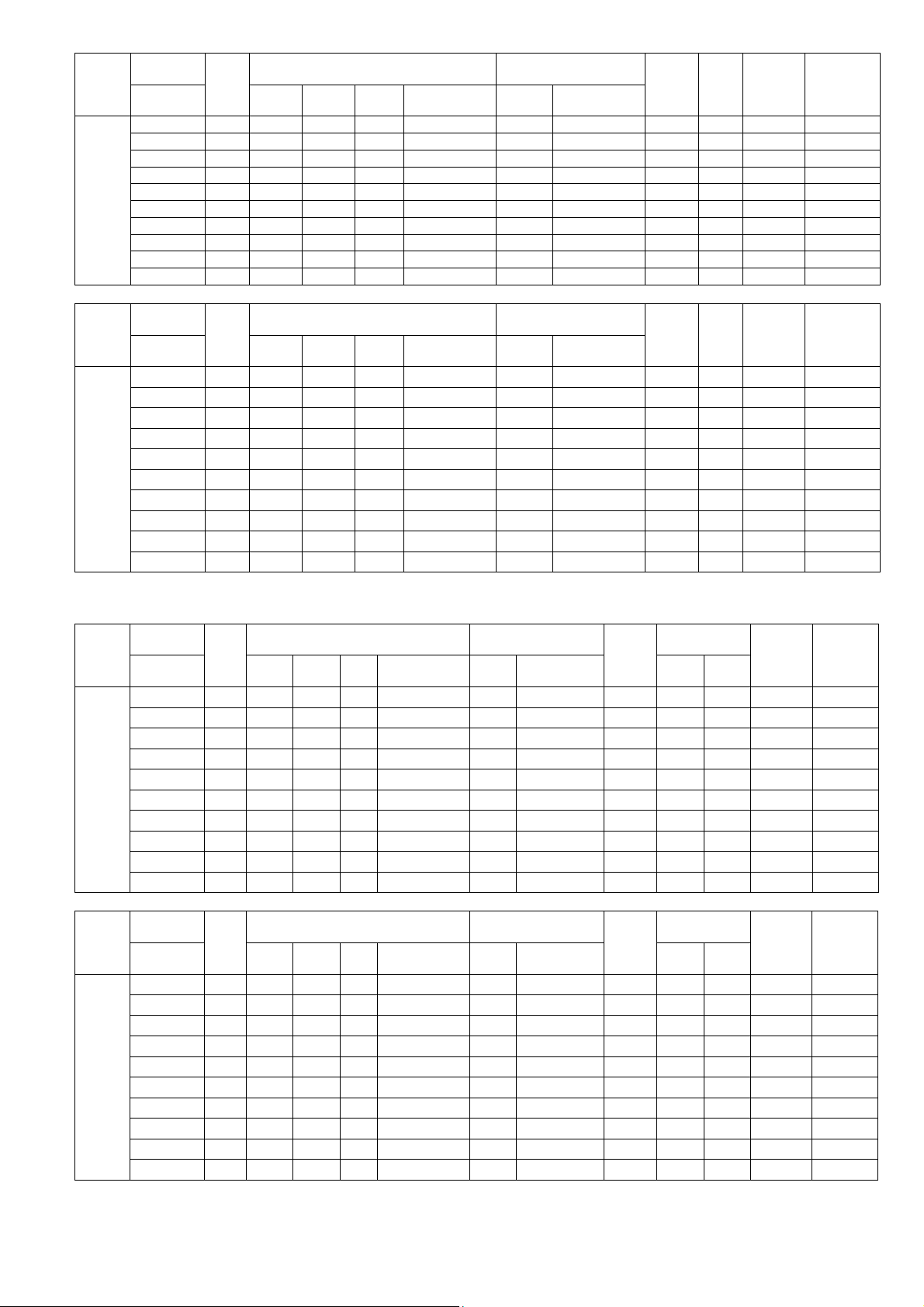
2 Room
Indoor unit
capacity
Cooling
1.6 + 1.6 3.2 1.620 1.620 3.24 2.10 ~ 3.89 770 360 ~ 960 4.20 19.00 3.6 0.3 + 0.3
1.6 + 2.0 3.6 1.613 2.017 3.63
1.6 + 2.5 4.1 1.616 2.524 4.14 2.10 ~ 4.97 1030 360 ~ 1370 4.02 19.00 4.7 0.3 + 0.5
1.6 + 3.2 4.8 1.610 3.220 4.83 2.10 ~ 5.80 1290 360 ~ 1680 3.74 19.00 5.8 0.3 + 0.6
2.0 + 2.0 4.0 2.010 2.010 4.02 2.10 ~ 4.82 980 360 ~ 1310 4.10 19.00 4.5 0.4 + 0.4
2.0 + 2.5 4.5 2.013 2.517 4.53
2.0 + 3.2 5.2 1.881 3.009 4.89 2.10 ~ 5.86 1330 360 ~ 1690 3.68 19.00 6.0 0.4 + 0.6
2.5 + 2.5 5.0 2.445 2.445 4.89 2.10 ~ 5.86 1330 360 ~ 1690 3.68 19.00 6.0 0.5 + 0.5
2.5 + 3.2 5.7 2.145 2.745 4.89 2.10 ~ 5.86 1330 360 ~ 1690 3.68 19.00 6.0 0.5 + 0.6
3.2 + 3.2 6.4 2.445 2.445 4.89
Total
Room A Room
Cooling Capacity (kW) Input Power (W)
Total min ~ max Rating min ~ max
B
2.10 ~ 4.36
2.10 ~ 5.44
2.10 ~ 5.86
2 Room
Indoor unit
capacity
Cooling
1.6 + 1.6 3.2 5500 5500 11000 7200 ~ 13300 770 360 ~ 960
1.6 + 2.0 3.6 5511 6889 12400 7200 ~ 14900 860 360 ~ 1110
1.6 + 2.5 4.1 5502 8598 14100
1.6 + 3.2 4.8 5500 11000 16500 7200 ~ 19800 1290 360 ~ 1680
2.0 + 2.0 4.0 6850 6850 13700 7200 ~ 16400 980 360 ~ 1310
2.0 + 2.5 4.5 6844 8556 15400 7200 ~ 18500 1210 360 ~ 1580
2.0 + 3.2 5.2 6423 10277 16700 7200 ~ 20000 1330 360 ~ 1690
2.5 + 2.5 5.0 8350 8350 16700 7200 ~ 20000 1330 360 ~ 1690
2.5 + 3.2 5.7 7325 9375 16700
3.2 + 3.2 6.4 8350 8350 16700 7200 ~ 20000 1330 360 ~ 1690
Total
Cooling Capacity (BTU/hr) Input Power (W)
Room A Room
Total min ~ max Rating min ~ max
B
7200 ~ 16900
7200 ~ 20000
Specifications are subject to change without notice for further improvement.
2 Room
Indoor unit
capacity
Heating
1.6 + 1.6 3.2 2.350 2.350 4.70
1.6 + 2.0 3.6 2.329 2.911 5.24 2.11 ~ 6.29 1600 400 ~ 2020 3.26 9.50 8.50 7.2
1.6 + 2.5 4.1 2.181 3.409 5.59 2.11 ~ 6.71 1740 400 ~ 2170 3.20 9.50 8.50 7.8
1.6 + 3.2 4.8 1.980 3.960 5.94 2.11 ~ 7.13 1800 400 ~ 2340 3.30 9.50 8.50 8.0
2.0 + 2.0 4.0 2.890 2.890 5.78 2.11 ~ 6.94 1770 400 ~ 2260 3.26 9.50 8.50 7.8
2.0 + 2.5 4.5 2.640 3.300 5.94 2.11 ~ 7.13 1870 400 ~ 2360 3.16 9.50 8.50 8.3
2.0 + 3.2 5.2 2.285 3.655 5.94
2.5 + 2.5 5.0 2.970 2.970 5.94 2.11 ~ 7.20 1750 400 ~ 2180 3.38 9.50 8.50 7.8
2.5 + 3.2 5.7 2.605 3.335 5.94 2.11 ~ 7.20 1750 400 ~ 2180 3.38 9.50 8.50 7.8
3.2 + 3.2 6.4 2.970 2.970 5.94 2.11 ~ 7.20 1750 400 ~ 2180 3.38 9.50 8.50 7.8
Total
Heating Capacity (kW) Input Power (W)
Room A Room
Total
B
min ~ max
2.11 ~ 5.64
2.11 ~ 7.20
Rating
1450
1750
2 Room
Indoor unit
capacity
Heating
1.6 + 1.6 3.2 8000 8000 16000 7200 ~ 19200 1450 400 ~ 1770 11.00 9.50 8.50 6.5
1.6 + 2.0 3.6 7956 9944 17900 7200 ~ 21400 1600 400 ~ 2020 11.15 9.50 8.50 7.2
1.6 + 2.5 4.1 7454 11646 19100 7200 ~ 22800 1740 400 ~ 2170 10.95 9.50 8.50 7.8
1.6 + 3.2 4.8 6733 13467 20200 7200 ~ 24400 1800 400 ~ 2340 11.20 9.50 8.50 8.0
2.0 + 2.0 4.0 9850 9850 19700
2.0 + 2.5 4.5 8978 11222 20200 7200 ~ 24400 1870 400 ~ 2360 10.80 9.50 8.50 8.3
2.0 + 3.2 5.2 7769 12431 20200 7200 ~ 24600 1750 400 ~ 2180 11.50 9.50 8.50 7.8
2.5 + 2.5 5.0 10100 10100 20200 7200 ~ 24600 1750 400 ~ 2180 11.50 9.50 8.50 7.8
2.5 + 3.2 5.7 8860 11340 20200 7200 ~ 24600 1750 400 ~ 2180 11.50 9.50 8.50 7.8
3.2 + 3.2 6.4 10100 10100 20200 7200 ~ 24600 1750 400 ~ 2180 11.50 9.50 8.50 7.8
Total
Heating Capacity (BTU/hr) Input Power (W)
Room A Room
Total min ~ max Rating min ~ max
B
7200 ~ 23600
1770
Specifications are subject to change without notice for further improvement.
860
1210
1330
1030
1330
min ~ max
400 ~ 1770
400 ~ 2180
400 ~ 2260
360 ~ 1110
360 ~ 1580
360 ~ 1690
360 ~ 1370
360 ~ 1690
COP
W/W
3.24 9.50 8.50 6.5
3.38 9.50 8.50 7.8
COP
Btu/h.W
11.10 9.50 8.50 7.8
EER
SEER
W/W
4.22 19.00 4.0 0.3 + 0.4
3.74 19.00 5.5 0.4 + 0.5
3.68 19.00 6.0 0.6 + 0.6
EER
Btu/h.W
14.25
14.40
13.65
12.75
13.95
12.70
12.55
12.55
12.55
12.55
SEER
19.00 3.6 0.3 + 0.3
19.00 4.0 0.3 + 0.4
19.00 4.7 0.3 + 0.5
19.00 5.8 0.3 + 0.6
19.00 4.5 0.4 + 0.4
19.00 5.5 0.4 + 0.5
19.00 6.0 0.4 + 0.6
19.00 6.0 0.5 + 0.5
19.00 6.0 0.5 + 0.6
19.00 6.0 0.6 + 0.6
HSPF
Region
IV
HSPF
Region
IV
Region
V
Region
V
Current,
230V (A)
Current,
230V (A)
Current,
230V
(A)
Current,
230V
(A)
Moisture
Removal
Volume (l/h)
Moisture
Removal
Volume (l/h)
Moisture
Removal
Volume
(l/h)
Moisture
Removal
Volume
(l/h)
7
Page 8
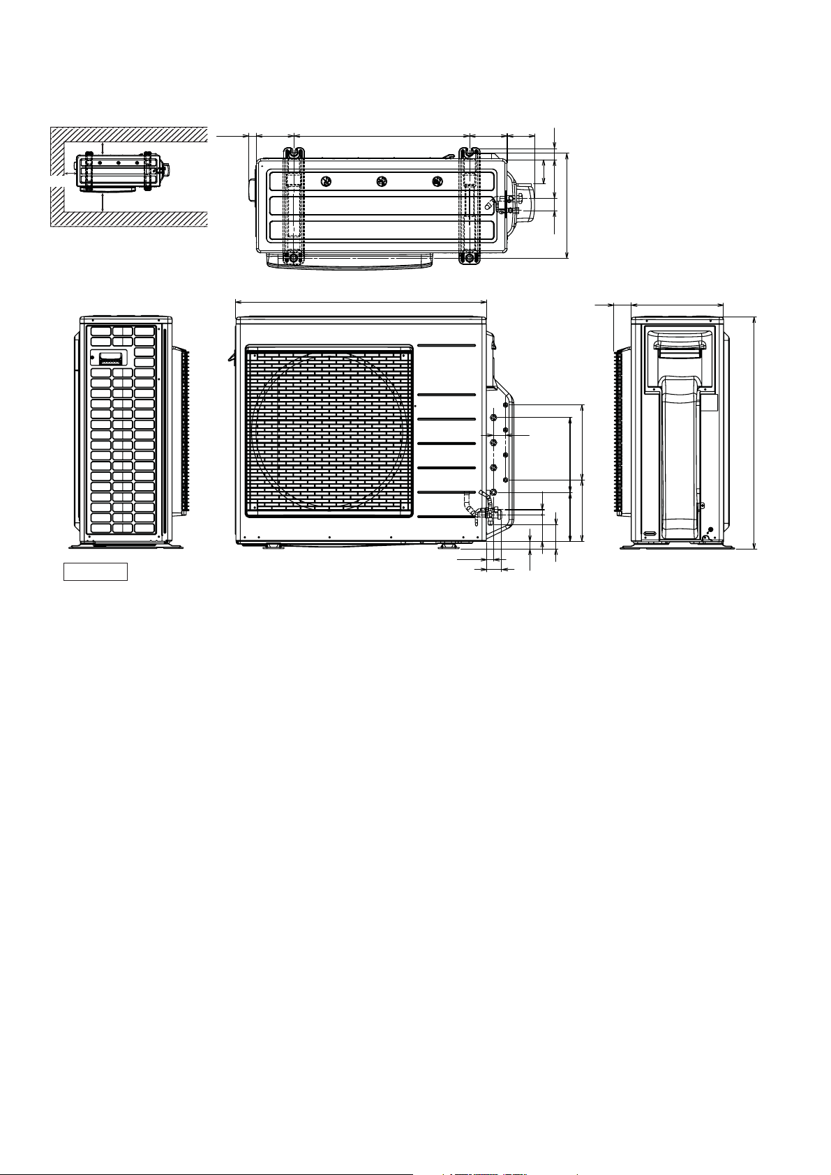
3. Dimensions
Space necessary for
installation
3-7/8
1-3/32
<Top View>
(5-5/32)
24-1/8
5-5/32 3-3/4
1-1/2
3-7/8
Anchor Bolt Pitch
14-13/64 x 24-1/8
<Side View>
Unit: inch
39-3/38
<Front View>
34-15/32
3-9/32
5-7/321-5/8
14-3/6
<Side View>
2-5/16 12-5/8
15/16
2-1/2
1-21/32
(63/64)
43/64
3-19/32
(3-3/16)
3-3/8 x 3 = 10-1/8
3-3/8 x 3 = 10-1/8
(8-9/32)
(6-9/16)
31-5/16
8
Page 9
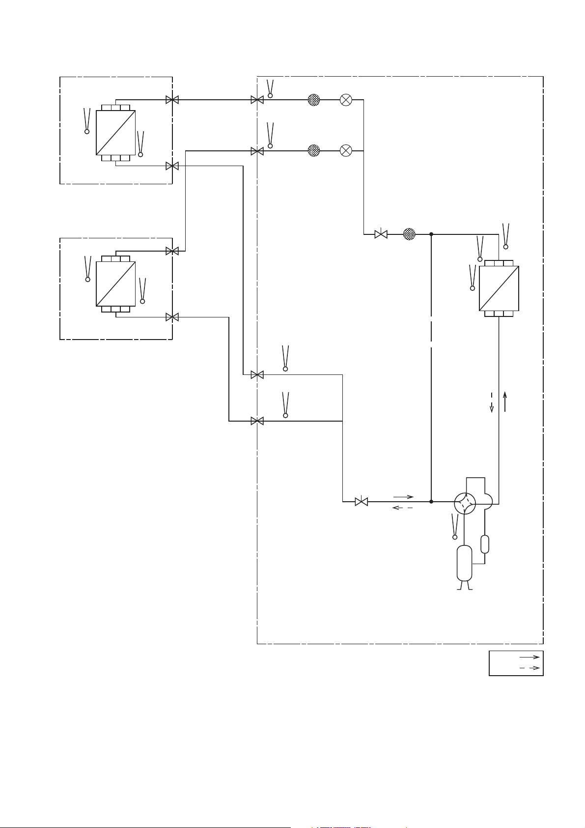
4. Refrigeration Cycle Diagram
INDOOR A
LIQUID SIDE
3- WAY VALVE
INTAKE
TEMP.
SENSOR
HEAT
EXCHANGER
(EVAPORATOR)
INTAKE
TEMP.
SENSOR
HEAT
EXCHANGER
(EVAPORATOR)
PIPE
TEMP.
SENSOR
PIPE
TEMP.
SENSOR
LIQUID SIDE
3- WAY VALVE
3- WAY VALVE
GAS SIDE
3- WAY VALVE
GAS SIDE
PIPE
TEMP.
SENSOR
PIPE
TEMP.
SENSOR
STRAINER
STRAINER
EXPANSION
VALVE A
EXPANSION
VALV E B
OUTDOOR
STRAINER3- WAY VALVE
CONDENSOR
DISCH.
PIPE TEMP.
SENSOR (DEF)
INTAKE
TEMP.
SENSOR
HEAT
EXCHANGER
(CONDENSOR)
TEMP.
SENSOR
INDOOR B
PIPE
TEMP.
SENSOR
PIPE
TEMP.
SENSOR
3- WAY VALVE
COMPRESSOR
TEMP.
SENSOR
COMPRESSOR
9
COOLING
HEATING
Page 10
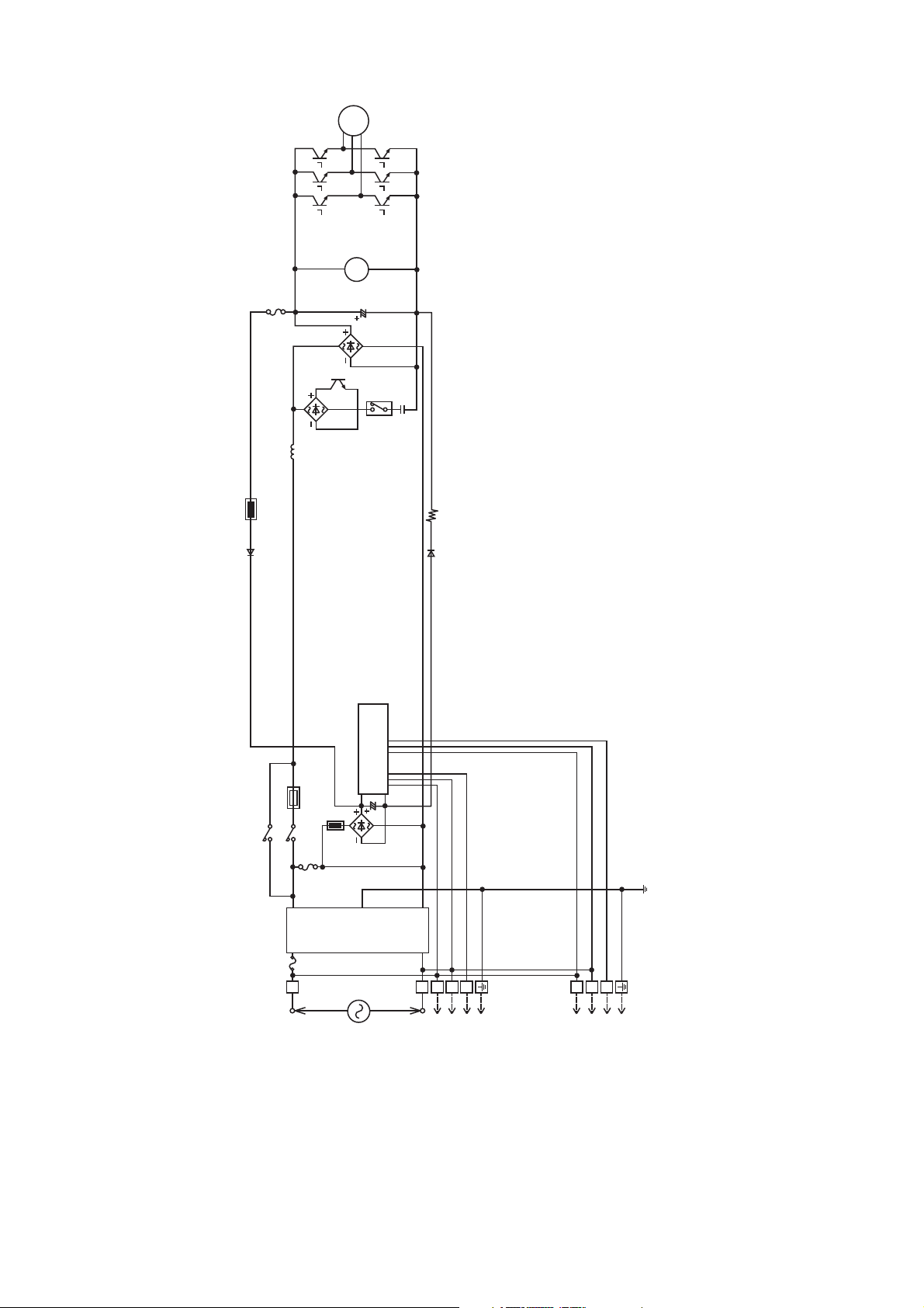
5. Block Diagram
COMP
FM
FUSE
L
REACTOR
SC
FUSE
NOISE
FILTER
L
POWER
SUPPLY
1
2
3
N
TO INDOOR UNIT ATO INDOOR UNIT B
123
10
Page 11
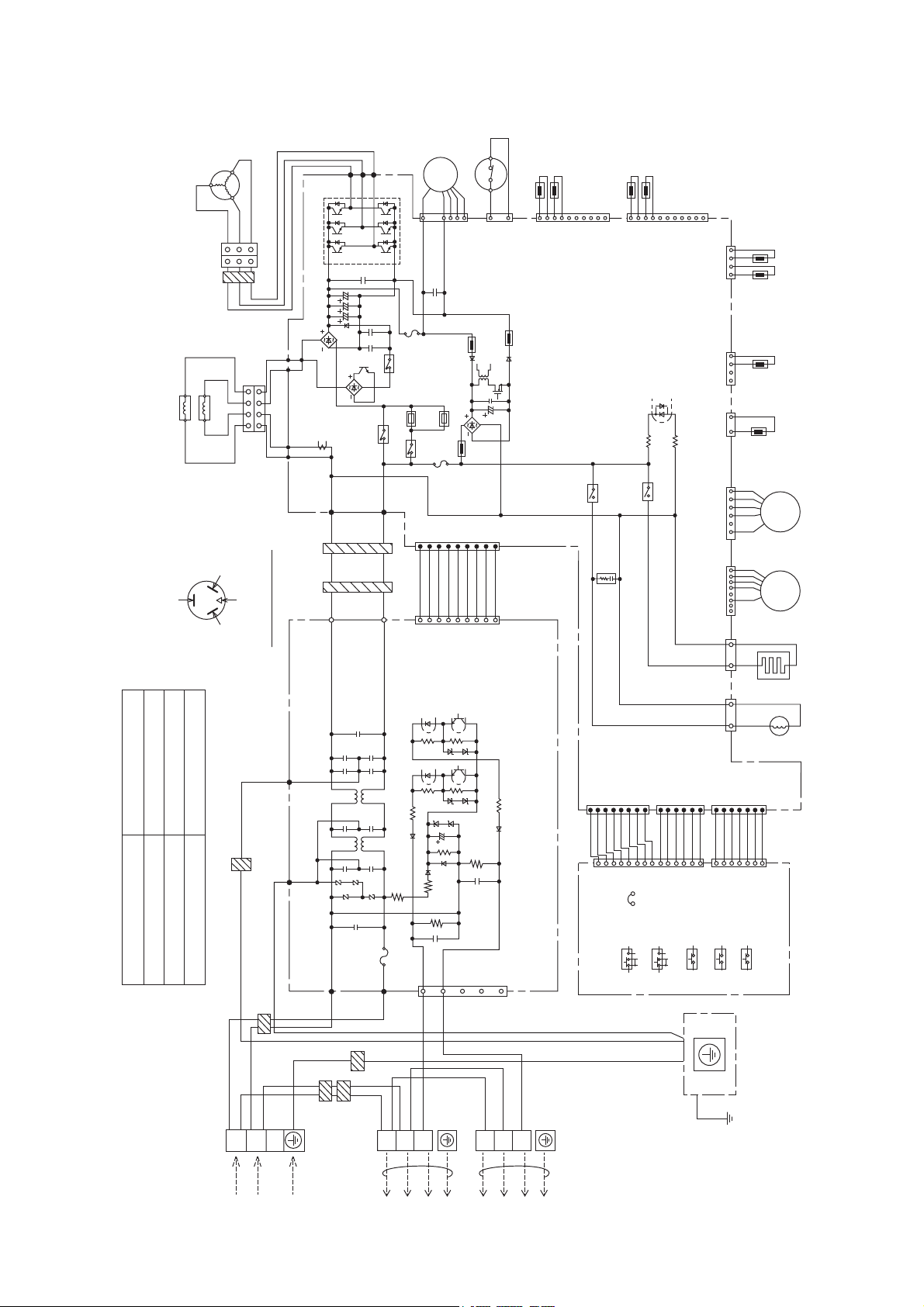
6. Wiring Connection Diagram
V
U
W
DB3
LL
L
L
P
DB1
1
L
L
N
L
FUSE1
T 3.15A
RY-C
BLU
RED
33
BLU
RED
BLK
BLK
1
COMPRESSOR
YLW
11
CORE
YLW
1
L 250V
FM
FAN MOTOR
7
WHITE
CN-FM1
RED
1
BLUE
CN-PSW1
T1
HIGH PRESSURE SW.
RED
2
LIQUID PIPE
SENSOR A
LIQUID PIPE
SENSOR B
1
WHITE
CN-TH3
GAS PIPE
GAS PIPE
SENSOR A
SENSOR B
SENSOR COMPLETE
1
10
CN-TH4
SENSOR COMPLETE
11
WHITE
1411161
WHITE
CN-TH1
CN-TH2
YELLOW
(THERMISTOR)
OUTLET TEMP.SENSOR
SENSOR
COMPLETE
(THERMISTOR)
COND.TEMP.SENSOR
(THERMISTOR)
SENSOR
COMPLETE
PIPE TEMP.SENSOR (DEF)
CONNECTION 5KD184XAB21 ()
REACTOR
YELLOW (W)
0.720
0.726
U - V
U - W
GRY
0.708
V - W
REACTOR
GRY
4
WHITE
CONNECTOR
RED (U)BLUE (V)
(TRADEMARK)
GRN
CORE
4
GRY BLK BLK
GRY
COMP. TERMINAL
GRN
L1-I L2-I L2-O L1-O
FG2
FG1
CT400
AC-WHT
CORE
CN-WHT
WHT
RY-PWR
AC-BLK
CN-BLK
CORE
BLK
PTC1
RY-AC
1
WHT
1
WHT
PTC2
T 2.5A
FUSE2
WHT
WHT
DB2
L 250V
WHT
WHT
WHITE
CN-DATA
WHT
WHT
WHITE
CN-DATA
9
WHT
9
ELECTRONIC CONTROLLER
(MAIN)
WHT
COOL ONLY
WHITE
CN-DISP 1
WHT
WHT
8
WHT
RY-HT
1
WHT
WHT
WHITE
1
WHT
WHT
WHT
1
RY-HOT
CR3
WHT
JP1
WHT
CN-DISP 1
WHITE
CN-DIS
CN-EV2
YELLOW
WHT
WHT
WHT
WHITE
M M
YELLOW
CN-NMODE
7
WHT
7
CN-NMODE 1
WHITE
CN-EV1
824
CN-HT
BLACK
1133
BLUE
CN-HOT
WHITE
CN-DISP 2
6
1
WHT
WHT
WHT
WHT
WHT
WHT
1
14
SENSOR
COMPLETE
(THERMISTOR)
DIS.T.TEMP.SENSOR
ELECTRO-
MAGNETIC COIL
(EXPAND VALVE)
ELECTRO-
MAGNETIC COIL
(EXPAND VALVE)
CASE
CRANK
HEATER
COIL
ELECTRO-
MAGNETIC
(4 WAY VALVE)
Resistance of Compressor Windings
BLK
BLK
L1
WHT
CORE
WHT
L2
Y/G
POWER SUPPLY
WHITE
ACN1
CORE
TERMINAL BOARD
CORE
BLACK
ACL1
CORE
1
TERMINAL BOARD
30A 250V
FUSE 401
CN-COM
RED
2
PRIORITY MODE
PUMP DOWN
WIRING CHECK
OPERATION TEST
Y/G
GROUND PLATE
REMARKS
BLU: BLUE
BLK: BLACK
WHT: WHITE
RED: RED
YLW: YELLOW
GRY: GRAY
GRN: GREEN
Y/G: YELLOW/GREEN
1
3
5
7
9
ELECTRONIC CONTROLLER
(SUB)
BLU
WHT
BLK
3
TO INDOOR UNIT ATO INDOOR UNIT B
1
2
3
POWER SAVE
ELECTRONIC CONTROLLER
(DISPLAY)
11
Page 12
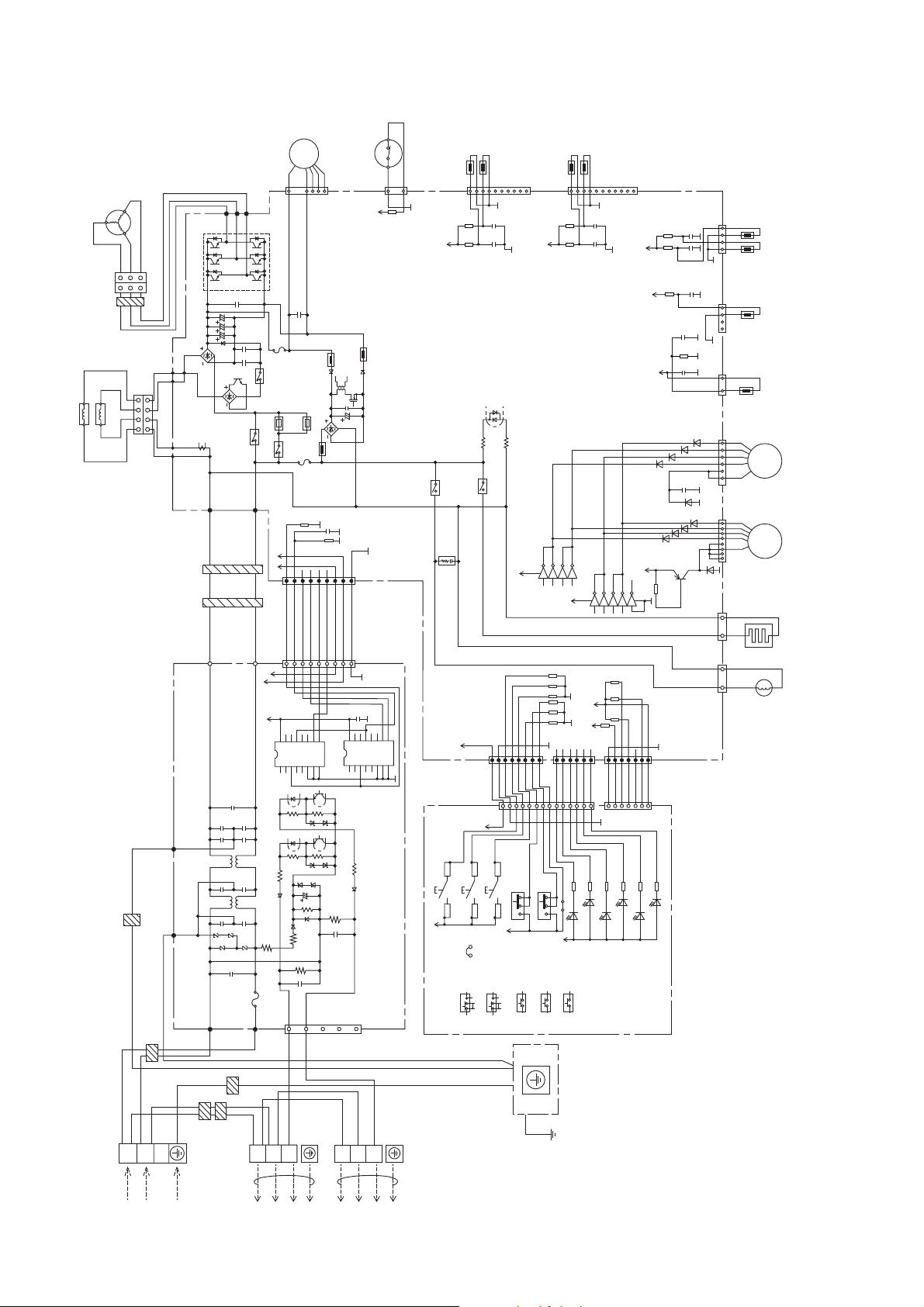
7. Electronic Circuit Diagram
FM
FAN MOTOR
1
7
1000p
47k
WHT
WHT
IC18
TC4052B
T1
9
WHT
9
1u
KB
16V
C212
16151413121110
2X
1X
VDD
X-COM
0Y2YY-C O M3Y1Y
1234567
13V
0X
V
COMPRESSOR
BLU
YLW
RED
33
CORE
BLU
YLW
RED
11
P
U
W
LL
L
L
L
L
N
WHITE
CN-FM1
DB3
BLK
BLK
1
1
REACTOR
REACTOR
4
4
WHITE
CONNECTOR
GRY BLK BLK
GRY
L1-I L2-I L2-O L1-O
GRY
GRY
AC-WHT
CORE
DB1
CT400
L
RY-C
RY-PWR
AC-BLK
FUSE1
PTC1
RY-AC
5V13V
T 3.15A
1
L 250V
PTC2
T 2.5A
FUSE2
10k
R253
DB2
L 250V
C276
R388
CORE
WHT
WHT
WHT
WHT
WHT
WHT
WHT
CN-WHT
BLK
5V
CN-BLK
5V
IC17
1
13V
16151413121110
VDD
TC4052B
0Y2YY-C O M3Y1Y
1234567
9
A
B
2X
1X
0X
3X
X-COM
INH
VEE
VSS
8
FG2
GRN
CORE
FG1
GRN
HIGH PRESSURE SW.
RED
RED
1
2
BLUE
5.6k
R138
CN-PSW1
ELECTRONIC CONTROLLER
(MAIN)
WHITE
CN-DATA
WHITE
CN-DATA
9
A
B
3X
INH
VEE
VSS
8
3
SW1
1
5V
5V
RY-HOT
CR3
4
2
JP1
LIQUID PIPE
SENSOR A
1
1%
R338
15.8k
1%
R333
15.8k
5V
3
4
SW2
1
2
COOL ONLY
LIQUID PIPE
SENSOR B
SENSOR COMPLETE
1u
6.3V
C241
WHITE
CN-TH3
1u
6.3V
C232
RY-HT
13V
WHITE
CN-DISP 1
1
WHT
WHT
WHT
WHT
WHT
WHITE
1
CN-DISP 1
5V
3
4
SW3
SW4
1
2
ON OFF
5V
10
161514
9
B1HBGFF00007
IC8
1
VCC
WHT
WHT
WHT
123
SW5
ON OFF
5V
234
8
IC8
R370 10k
R371 10k
R372 10k
R375 10k
R374 10k
R373 10k
1
WHT
123
WHT
5V
GAS PIPE
SENSOR A
1
1%
R342
15.8k
1%
R341
15.8k
13
IC8
IC8
13V
WHT
WHT
R304 1.2k
JP1
GREEN
GAS PIPE
B1HBGFF00007
WHITE
WHT
LED1
SENSOR B
SENSOR COMPLETE
11
1u
6.3V
WHITE
C240
CN-TH4
1u
6.3V
C239
9
IC15
IC15
IC15
IC15
IC15
116
215
314
413
710
VCC
10k
R147
10k
R146
5V
10k
R386
5V
10k
R256
CN-DISP 2
6
1
WHT
WHT
WHT
WHT
WHT
WHT
1
14
R307 1.2k
R306 1.2k
R305 1.2k
LED4
LED2
LED3
GREEN
GREEN
GREEN
5V
5V
5V
13V
10k
R365
GND
8
7
WHT
WHT
WHITE
7
CN-NMODE 1
R308 1.2k
LED5
GREEN
1%
R101
7.50k
1%
R100
15.0k
1%
R103
7.50k
D64
e
2SB1188
R309 1.2k
LED6
GREEN
WHITE
CN-TH1
1411161
1u
C46
6.3V
SENSOR
1u
C45
6.3V
1u
C48
6.3V
CN-TH2
YELLOW
1u
C47
6.3V
1%
R102
4.99k
1u
KB
6.3V
C209
WHITE
CN-DIS
CN-EV2
YELLOW
D61
D62
D63
KB
25V
C218
0.047u
D34
WHITE
CN-EV1
D57
D58
D59
D60
824
c
D33
Q25
b
CN-HT
BLACK
1133
BLUE
CN-HOT
COMPLETE
SENSOR
COMPLETE
SENSOR
COMPLETE
M M
CRANK
(THERMISTOR)
(THERMISTOR)
ELECTRO-
ELECTRO-
CASE
ELECTRO-
YELLOW
CN-NMODE
(THERMISTOR)
OUTLET TEMP.SENSOR
COND.TEMP.SENSOR
(THERMISTOR)
PIPE TEMP.SENSOR (DEF)
DIS.T.TEMP.SENSOR
MAGNETIC COIL
(EXPAND VALVE)
MAGNETIC COIL
(EXPAND VALVE)
HEATER
COIL
MAGNETIC
(4 WAY VALVE)
BLK
BLK
L1
WHT
WHT
L2
CORE
Y/G
POWER SUPPLY
WHITE
ACN1
CORE
TERMINAL BOARD
CORE
BLACK
ACL1
CORE
123
TERMINAL BOARD
30A 250V
FUSE 401
CN-COM
RED
13579
BLU
WHT
BLK
123
TO INDOOR UNIT ATO INDOOR UNIT B
ELECTRONIC CONTROLLER
(SUB)
POWER SAVE
ELECTRONIC CONTROLLER
(DISPLAY)
12
PRIORITY MODE
PUMP DOWN
WIRING CHECK
OPERATION TEST
Y/G
GROUND PLATE
Page 13
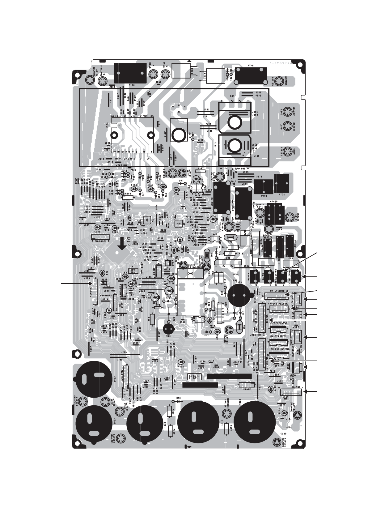
8. Printed Circuit Board
8.1 Main Printed Circuit Board
CN- DATA
CN-HT
CN-HOT
CN-EV1
CN-TH1
CN-EV2
CN-DIS
CN-TH3
CN-TH2
CN-TH4
CN-PSW1
CN-FM1
13
Page 14
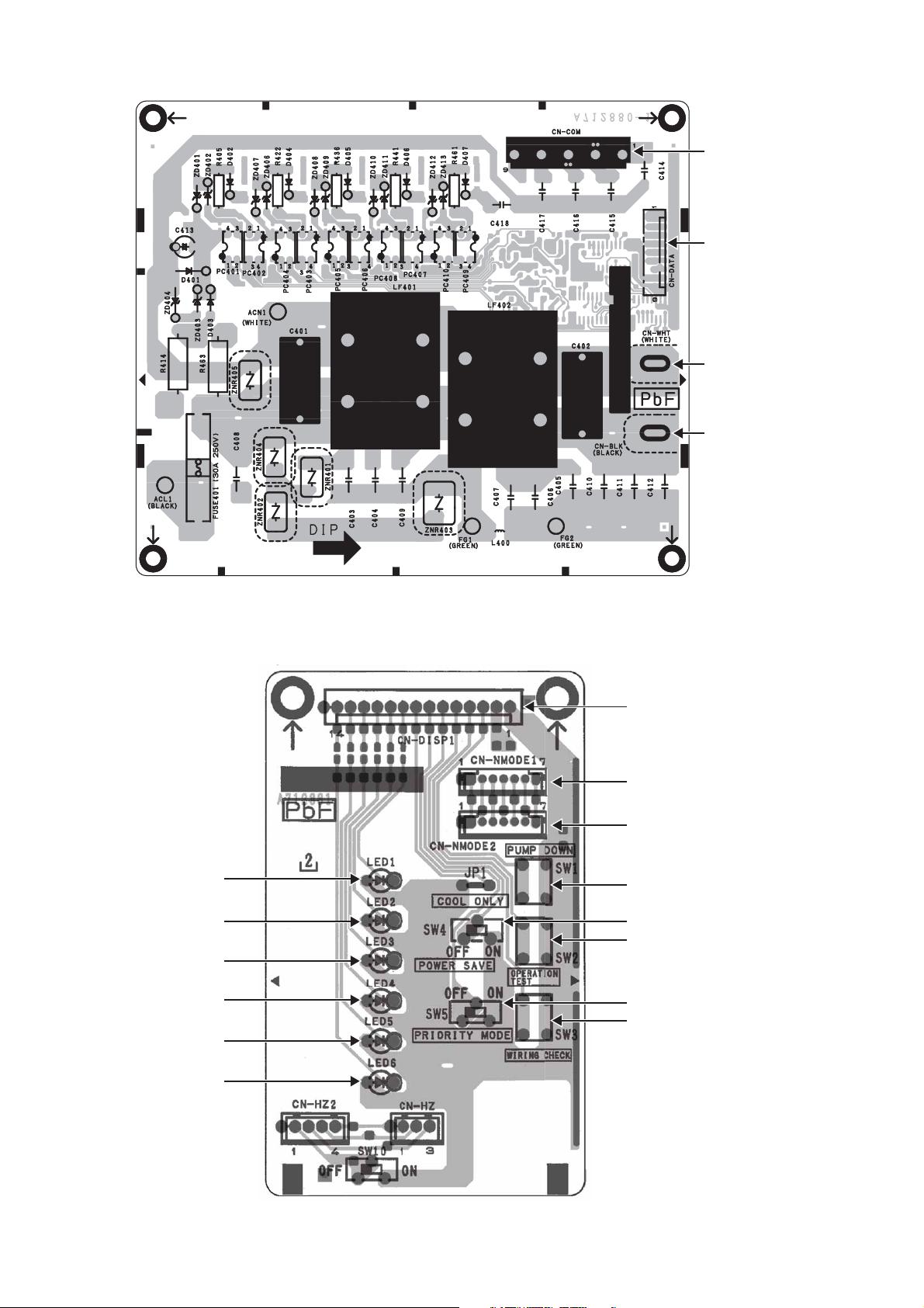
8.2 Noise Filter Printed Circuit Board
CN-COM
CN- DATA
CN-WHT
CN-BLK
8.3 Display Printed Circuit Board
LED1
LED2
LED3
LED4
LED5
CN-DISP1
CN-NMODE1
CN-NMODE2
SW1
SW4
SW2
SW5
SW3
LED6
14
Page 15

9. Installation Information
9.1 Check Points
49.2 ft max.
82 ft
82 ft
Total maximum pipe length: 164 ft
QUICK GUIDE PIPING AND ELECTRICAL SPECIFICATION
Indoor (ID) &
Outdoor (OD)
units: Possible
Combination
Patterns
Outdoor (OD):
CU-2E18SBU
Indoor (ID): 2
UNITS OF CSE9RKUAW
Outdoor (OD):
CU-2E18SBU
Indoor (ID): 2
UNITS OF CSE12RKUAW
Outdoor (OD):
CU-2E18SBU
Indoor (ID): 1
UNIT OF CSE9RKUAW +
1 UNIT OF
CS-E12RKUAW
Capacity
(Btu/h)
16700 R410A
Refrige-
rant
Piping size
Gas Liquid
Ø3/8”
(Ø9.52mm)
Ø1/4”
(Ø6.35mm)
Standard
pipe
length
24.6 ft
Max.
Eleva-
tion
See
Step 1
Min.
Max.
pipe
length
each ID
from
OD to
for
each
ID unit
unit
9.8 ft 82.0 ft 164.0 ft 65.6 ft
Max.
total
length
Min. total
pipe
length
for
additional
gas
Additional
refri-
ge-
rant
0.2
oz / ft
Power
supply
208/230V
60 Hz
MCA 20A
MOP
25A
Power
supply
wire
size
AWG12 AWFG16
OD-ID
connection
wire size
Example:
If total piping length of all installed indoor units is at 68.6 ft, the quantity of additional refrigerant should be 0.6 oz ......
(68.6 - 65.6) ft x 0.2 oz/ft = 0.6 oz.
15
Page 16

10. Installation Instruction
IMPORTANT
This product has been designed and manufactured to meet ENERGY STAR
matched with appropriate coil components. However, proper refrigerant charge and proper air flow are critical to
achieve rated capacity and efficiency. Installation of this product should follow the manufacturer’s refrigerant charging
and air flow instructions. Failure to confirm proper charge and airflow may reduce energy efficiency and
shorten equipment life.
10.1 Accessories Supplied with Outdoor Unit
The following parts are supplied as accessories with each outdoor unit.
Check that all accessory parts are present before installing the outdoor unit.
HEAT PUMP-TYPES ONLY
Part name Qty. Diagram Application
®
criteria for energy efficiency when
Drain elbow 1
For connecting the drain pipe
10.2 Cutting and Flaring the Piping
1 Please cut using pipe cutter and then remove the burrs.
2 Remove the burrs by using reamer. If burrs is not removed, gas leakage may be caused.
Turn the piping end down to avoid the metal powder entering the pipe.
3 Please make flare after inserting the flare nut onto the copper pipes.
1. To cut
Point down
2. To remove burrs
Pipe
Reamer
Bar
Clamp handle
3. To fl are
Handle
Yo k e
Core
Red arrow mark
Bar
1
0 –
/32"
(0-0.5 mm)
Copper pipe
When properly fl ared, the internal surface
of the fl are will evenly shine and be of
even thickness. Since the flare part
comes into contact with the connections,
carefully check the fl are fi nish.
Improper fl aring
Inclined Surface
damaged
Cracked Uneven
thickness
16
Page 17

10.3 Select the Best Location
10.3.1 Outdoor Unit
If an awning is built over the unit to prevent direct
sunlight or rain, be careful that heat radiation from
the condenser is not obstructed.
There should not be any animal or plant which
could be affected by hot air discharged.
Keep the spaces indicated by arrows from wall,
ceiling, fence or other obstacles.
Do not place any obstacles which may cause a
short circuit of the discharged air.
Recommended installation height for outdoor unit
should be above the seasonal snow level.
Refrigerant piping size
Outdoor Unit CU-2E18**
Liquid - side ø1/4" (ø6.35 mm) thickness 1/32" (t0.8 mm)
Gas - side ø3/8" (ø9.52 mm) thickness 1/32" (t0.8 mm)
Outdoor Unit CU-2E18**
Min. total piping length for additional gas 65.6 ft (20 m)
If total piping length of all indoor units exceeds the
minimum length listed above, additionally charge
with 0.2 oz (20 g) of refrigerant (R410A) for each
additional feet (meter) of piping.
Allowable piping length
Outdoor Unit CU-2E18***
Allowable piping length of each indoor unit (min. ~ max.) 9.8 ft ~ 82.0 ft (3 m ~ 25 m)
Allowable total piping length of all indoor units 164.0 ft (50 m) or less
Height difference between indoor and outdoor units
Height difference between indoor units
Outdoor unit located on upper side
Outdoor unit located otherwise
Outdoor unit located on upper side
Outdoor unit located otherwise
Outdoor Unit Installation Diagram
This illustration is for explanation purposes only.
* Note:
Respective indoor unit installation procedure shall
refer to instruction manual provided in the indoor
unit packaging.
a
b
c
d
Installation parts you
should purchase (
It is advisable to avoid more
than 2 blockage directions.
For better ventilation &
multiple-outdoor installation,
please consult authorized
dealer/specialist.
Power supply cord (
(Conduit)
Connection cable (
(Conduit)
Additional drain hose (
1
4
" (6.35 mm)
/
Liquid side piping (
3
/8" (9.52 mm)
Gas side piping (
49.2 ft (15 m) or less
24.6 ft (7.5 m) or less
24.6 ft (7.5 m) or less
49.2 ft (15 m) or less
)
)
)
)
)
)
Outdoor unit located
on upper side
a
c
I
Outdoor unit
d
b
Outdoor unit located
otherwise
Indoor unit
d
Outdoor unit
b
roodnItinu roodn
tinu
17
Outdoor unit
Page 18

Outdoor Unit Installation Guidelines
f
Where a wall or other obstacle is in the path of outdoor unit’s intake or exhaust airflow, follow the installation
guidelines below.
For any of the below installation patterns, the wall height on the exhaust side should be 47 1/4" (1200 mm) or
less.
Wall facing one side
More than 3 15/16" (100)
47
1
/4" (1200)
or less
More than
3
" (1000)
39
/
8
Walls facing two side Walls facing three side
/16"
More than
15
3
/
More than
3
39
Top view
/8" (1000)
" (100)
16
Unit : inch (mm)
More than
15
/16" (100)
3
More than
15
/16" (100)
3
weiv poTweiv ediS
More than
3
/
8
39
" (1000)
More than
13
/
16
11
" (300)
More
than
15
3
(100)
10.4 Install the Outdoor Unit
After selecting the best location, start installation
to Indoor/Outdoor Unit Installation Diagram.
1 Fix the unit on concrete or rigid frame firmly
and horizontally with bolt nut (ø13/32"
(ø10 mm)).
2 When installing on a roof, please consider
strong winds and earthquakes.
3 Please fasten the installation stand firmly with
bolt or nails.
10.5 Connect the Piping
Remove the control board cover (resin) from the
outdoor unit by loosening three screws.
Connecting the Piping to Outdoor Unit
Decide piping length and then cut by using pipe
cutter.
Remove burrs from cut edge. Make flare after
inserting the flare nut (locate at valve) onto the
copper pipe.
Align center of piping to valves and then tighten
with torque wrench to the specified torque as
stated in the table.
Screws
Control Board Cover (Resin)
Liquid side
Gas side
AB
C
D
Model A B C D
CU-2E18***
24 1/8"
(613 mm)
5 5/32"
(131 mm)
5/8"
(16 mm)
14 3/16"
(360.5 mm)
Do not overtighten, over tightening may cause gas leakage.
Piping size Torque
1/4" (6.35 mm) 13.3 Ibf•ft [18 N•m (1.8 kgf•m)]
3/8" (9.52 mm) 31.0 Ibf•ft [42 N•m (4.3 kgf•m)]
1/2" (12.7 mm) 40.6 Ibf•ft [55 N•m (5.6 kgf•m)]
5/8" (15.88 mm) 47.9 Ibf•ft [65 N•m (6.6 kgf•m)]
3/4" (19.05 mm) 73.8 Ibf•ft [100 N•m (10.2 kgf•m)]
Flare Nut
(Connection Pipe)
Torque Wrench for Flare Nut
Flare Nut
(Connection Pipe)
Female side
Applicable to
Liquid and Gas side o
CS-E9***
CS-E12***
CS-ME5***
CS-ME7***
CS-ME9***
Male side
Screw
Torque Wrench for Flare Nut
Gas Leak Checking
Pressure test to system to 400 PSIG with dry nitrogen, in stages. Thoroughly leak check the system.
If the pressure holds, release the nitrogen and proceed to section 10.7.
18
Page 19

10.6 Evacuation of the Equipment
WHEN INSTALLING AN AIR CONDITIONER, BE SURE TO EVACUATE THE AIR INSIDE THE INDOOR UNIT AND
PIPES in the following procedure.
1 Connect a charging hose with a push pin to
the Low side of a charging set and the service
Indoor Unit
port of the gas side 3-way valve.
2 Connect the micron gauge between vacuum
pump and service port of outdoor units.
3 Turn on the power switch of the vacuum pump
and make sure that connect digital micron
gauge and to pull down to a value of
500 microns.
Indoor Unit
4 To make sure micron gauge a value
500 microns and close the low side valve of
the charging set and turn off the vacuum
pump.
5 Disconnect the vacuum pump house from the
service port of the 3-way valve.
6 Tighten the service port caps of gas side
3-way valve at a torque of 13.3 Ibf•ft (18 N•m)
with a torque wrench.
7 Remove the valve caps of both of the 2-way
Vac uum
pump
valve and 3-way valve. Position both of the
valves to “Open” using a hexagonal wrench
(5/32" (4 mm)).
8 Mount valve caps onto the 2-way valve and
3-way valve.
o Be sure to check for gas leakage.
If micron gauge value does not descend 500 microns, take the following measures:
- If the leak stops when the piping connections are tightened further, continue working from step 3.
- If the leak does not stop when the connections are retightened, repair location of leak.
- Do not release refrigerant during piping work for installation and reinstallation.
- Take care when handling the liquid refrigerant, it may cause frostbite.
Tube connector
Liquid side
Tube connector
Gas
side
Tube connector
Liquid side
Tube connector
Gas
side
Liquid side 3-way valve
Gas side 3-way valve
Close
Close
Outdoor unit
19
Page 20

10.7 Connect the Cable to the Outdoor Unit
1 Remove Control Board Cover (Metal) by
loosening 2 screws.
2 Remove Valve Cover (Metal) by loosening
2 screws.
3 Remove Plugs.
4 Fix the conduit connectors to the knock out
holes with lock-nuts, then secure them.
5 Connecting wire between indoor unit and
outdoor unit should be UL listed or CSA
approved 4 conductor wires minimum AWG16
in accordance with local electric codes.
6 Wire Connection to the power supply
(208/230V 60Hz) through circuit breaker.
o Connect the UL listed or CSA approved
wires minimum AWG12 to the terminal
board, and connect to other end of the
wires to circuit breaker.
7 Connect the power supply cord and
connecting wires between indoor unit and
outdoor unit according to the diagram as
shown.
Indoor
Unit A
Terminal
1
2
3
208/230V min AWG16
208/230V min AWG16
208/230V min AWG16
Grounding wire min AWG16
Outdoor Unit
Terminal
1
2
Unit A
3
Screws
Valve Cover
Screws
Lock Nuts
(Metal)
Side Panel
To p Pa n e l
Control Board Cover
(Metal)
Connectors
Plugs
Knock Out Holes
Unit B
Unit A
Indoor
Unit B
Terminal
1
2
3
208/230V min AWG16
208/230V min AWG16
208/230V min AWG16
Grounding wire min AWG16
1
2
Unit B
3
L1
L2
Disconnect
Switch
Field supply
Grounding wire
Power Supply
Single Phase
208/230V 60Hz
min AWG12
Power Supply
Cord
Indoor & outdoor
connection wire
Indoor
Unit A
8 For wire stripping and connection requirement, refer to the diagram below.
9 Secure the power supply cord and connection cables onto the control board with the holder.
10 Attach the control board cover (metal and resin) and valve cover back to the original position with screw.
WIRE STRIPPING AND CONNECTING REQUIREMENT
Wire stripping
"
16
/
1
" ±
32
(10±1 mm)
/
13
No loose strand when inserted
Indoor/outdoor
connecting
terminal board
7
/32" (5 mm)
or more
(gap between
wires)
Conductor fully
inserted
ACCEPT PROHIBITED PROHIBITED
Conductor over
inserted
Conductor not
fully inserted
This equipment must be properly earthed.
o Earth wire must be Yellow/Green (Y/G) in colour and longer than other AC wires for safety reasons.
Indoor
Unit B
10.8 Heat Insulation
Use a material with good heat-resistant properties as the heat insulation for the
pipes. Be sure to insulate both the gas-side and liquid-side pipes. If the pipes are
not adequately insulated, condensation or water leakages may occur.
20
Liquid-side pipes
Gas-side pipes
Material shall
withstand 248°F
(120°C) or
higher
Page 21

11. Operation Control
11.1 Cooling Operation
11.1.1 Outdoor fan control
When cooling operation is enabled, based on outdoor ambient temperature, fan motor control will be adjusted
according to figure below:
59°F
8.6°F
OD temp.
RPM free
RPM controlled
Stopped
55.4°F
11.1.2 Annual Cooling control
This control is to enable cooling operation when outdoor ambient temperature is low.
Control start conditions:
o Cooling operation is activated with compressor ON.
o Outdoor ambient temperature is less than 59°F
Control contents:
o When the above conditions are fulfilled, based on outdoor pipe temperature, the outdoor fan motor will
operate according to figure below:
93.2°F
75.2°F
66.2°F
RPM up
RPM unchanged
RPM down
Stopped
91.4°F
73.4°F
64.4°F
OD Pipe temp.
To improve the judgment accuracy during annual cooling control, outdoor ambient temperature sampling for
2 minutes will be activated every 35 minutes under designated fan speed.
Control stop conditions:
o When either one of the start conditions are not complied.
21
Page 22

11.2 Heating Operation
11.2.1 Outdoor fan control
When heating operation is enabled, based on outdoor ambient temperature, fan motor control will be adjusted
according to figure below:
RPM controlled
57.2°F
RPM free
53.6°F
OD temp.
To improve the judgment accuracy, indoor room temperature sampling starts when any indoor unit has stopped
capability supplied (heating thermo-off) during heating operation with compressor ON, outdoor unit will send
signal to all thermo-off indoor units to ON fan motor and get room temperature sample.
To prevent discharge temperature drop at indoor units which is ON when sampling the room temperature of
heating thermo-off units, the outdoor fan speed will be adjusted accordingly.
However, if indoor room temperature is high compare to remote control setting temperature, sampling of
corresponding indoor unit will be cancelled.
11.2.2 Powerful Operation 1
During cooling operation, this control is to concentrate outdoor unit capability to the powerful operation enabled
indoor unit by temporary stop the capability supply to low load demand indoor units.
Operation start condition:
o Powerful operation ON for targeted indoor unit
Operation content:
o If other indoor units (where Powerful operation are OFF) achieve setting temperature continuously for
1 minute after received powerful command from indoor unit, then capability supply to other indoor units are
stopped for minimum 3 minutes.
Capability supply stop period follows powerful operation period.
Operation stops when comply either one of the following conditions:
o When other indoor units (where Powerful operation are OFF) is lower than setting temperature.
o When the powerful operation is OFF for all indoor units.
o When Quiet operation received from 1 indoor unit.
o When protection control starts.
11.2.3 Powerful Operation 2
During cooling / heating operation, this control is to provide fast cooling / heating operation compare to normal
operation.
Operation start if all condition below are complied:
o Powerful operation ON for indoor unit.
o Not under Annual Cooling control.
Operation content:
o Outdoor fan speed will adjust automatically.
o Compressor frequency will adjust automatically.
Operation stop when comply either one of the follow conditions:
o When the powerful operation is OFF for all indoor units.
o When annual cooling control activated.
22
Page 23

12. Simultaneous Operation Control
1 Operation modes which can be selected
using the remote control unit:
Automatic, Cooling, Soft Dry, Heating, e-ion
operation mode.
2 Types of operations modes which can be
performed simultaneously
o Cooling operation and cooling, Soft Dry
or e-ion operation
o Heating operation and heating operation
3 Types of operation modes which cannot be
performed simultaneously
o While a cooling operation is in progress,
a heating operation cannot be performed
by an indoor unit in another room.
In the room where the operation button
for cooling was pressed first, the
operation is continued. In the room where
the operation button for heating was
pressed afterward, the operation lamp of
the indoor unit blinks, where the attempt
is made to establish the heating
operation. Its fan is stopped, and the air
does not discharged.
o While a heating operation is in progress,
a cooling operation cannot be performed
by an indoor unit in another room.
In the room where the operation button
for heating was pressed first, the
operation is continued. In the room where
the operation button for cooling was
pressed afterward, the operation lamp of
the indoor unit blinks, where the attempt
is made to establish the cooling operation.
Its fan is stopped, and the air does not
discharged.
4 Operation mode priority control
o The operation mode designated first by
the indoor unit has priority.
o If the priority indoor unit stops operation
or initiates the e-ion operation, the priority
is transferred to other indoor units.
23
Page 24

13. Protection Control
13.1 Freeze Prevention Control (Cool)
When received freeze prevention signal from indoor unit, the compressor frequency changes according to indoor
heat exchanger temperature.
When indoor unit request capability OFF due to freeze condition , immediately the capability supply to targeted
indoor unit stops.
13.2 Dew Prevention Control (Cool)
When received dew prevention signal from indoor unit, the compressor frequency changes according to indoor
intake temperature and indoor heat exchanger temperature.
13.3 Electronic Parts Temperature Rise Protection 1 (Cool)
This control prevents electronic parts temperature rise during cooling overload condition.
Start conditions:
o Outdoor ambient temperature is at protection region as shown in figure below:
Protection
Region
89.6°F
Normal
Region
86°F
OD temp
o Outdoor unit total current is above 5.5A
Control content
o Outdoor fan speed is adjusted accordingly.
Control stop condition
o When outdoor ambient temperature is back to normal region.
During this control, outdoor fan speed does not reduce for Quiet operation.
13.4 Electronic Parts Temperature Rise Protection 2 (Cool)
This control prevents electronic parts temperature rise during cooling/dry operation.
Start conditions:
o Total current is at protection region as shown in figure below:
Protection
Region
4.7A
Normal
Region
Total current
Control content
o Outdoor fan speed is adjusted accordingly.
Control stop conditions
o When total current is back to normal region.
During this control, outdoor fan speed does not reduce for Quiet operation.
3.3A
24
Page 25

13.5 Cooling Overload Control (Cool)
p
p
This control detect outdoor pipe temperature and perform the compressor frequency restriction during cooling
operation.
147.2°F
140°F
OD Pipe
tem
Comp stop
Comp freq
restricted
Comp freq
free
134.6°C
13.6 Heating Overload Control (Heat)
This control detect indoor pipe temperature and perform the compressor frequency restriction during heating
operation.
140°F
127.4°F
118.4°F
ID Pipe
tem
This control detect outdoor ambient temperature and perform the fan speed adjustment during heating operation.
Comp stop
Comp freq
restricted
Comp freq
maintain
Comp freq
free
RPM controlled
53.6°F
50°F
RPM free
OD temp
13.7 Extreme Low Temperature Compressor Low Pressure Protection
Control (Heat)
This control is to prevent low pressure drops too low during extremely low outdoor ambient temperature to
improve the compressor reliability.
During heating operation, when outdoor ambient temperature is in Zone 1, this control will be activated.
Compressor frequency restriction will be based on outdoor piping temperature.
Comp freq
free
Zone 0
26.6°F
23°F
Zone 1
OD temp
-9.4°F
-14.8°F
Comp freq
restricted
Comp freq
stop
OD pipe
-5.8°F
-11.2°F
25
Page 26

13.8 Deice Control
When outdoor pipe temperature and outdoor air temperature is low, deice operation starts where indoor fan
motor and outdoor fan motor stop, indoor unit horizontal vane close and operation LED blink with compressor ON.
13.9 Time Delay Safety Control (Restart Control)
The compressor will not restart within three minutes after compressor is stopped.
This control is not applicable if the power supply reset or after deice condition.
13.10 30 seconds Force Operation
Once the compressor starts operation, it will not stop its operation for 30 seconds in order to cycle back
compressor oil.
However, it can be stopped using remote control or Auto OFF/ON button at indoor unit.
13.11 Total Current Control
By referring to table below, during normal (default) operation, the running current refer to Hi values and during
Power Save Mode, the running current refer to Lo values.
When the outdoor unit total running current (AC) exceeds X value, compressor frequency will decrease.
If the running current does not exceed X value for 5 seconds, compressor frequency will increase.
However, if total outdoor unit running current exceeds Y value, compressor will be stopped immediately for
3 minutes.
Operation Mode
Cooling/Soft Dry (A) 12.2 17.5
Cooling/Soft Dry (B) 11.5 17.5
Heating 13.2 17.5
X (A) Y (A)
CU-2E18SBU
B
43°C (109.4°F)
A
Outdoor Intake
Temperature
42°C (107.6°F)
13.12 IPM (power transistor) Protection Control
Overheating Prevention Control
o If IPM temperature rises to 176°F, outdoor fan speed will be increased.
o When the IPM temperature rises to 203°F, compressor operation will stop immediately.
o Compressor operation restarts when temperature decreases to 194°F.
o If IPM temperature detected less than -22°F, IPM is judged as open circuit (“F96” is indicated).
DC peak current control
o When IPM DC current exceeds set value of 30.0 ± 3.0 A, the compressor will stop.
o If the DC peak current detected within 30 seconds after operation starts, compressor will restart after
1 minute.
o If the DC peak current detected 30 seconds or more after operation starts, compressor will restart after
2 minutes.
o Within 30 seconds after compressor restarts, if the DC peak current is exceeded set value continuously for
7 times, all indoor and outdoor relays will be cut off (“F99” is indicated).
Error reset can be done by power supply reset.
26
Page 27

13.13 Compressor Protection Control (Gas leak detection control 1)
Control start conditions
o For 5 minutes, the compressor continuously operates and total current is low.
o During Cooling or Soft Dry operation:
Indoor intake temperature — indoor piping temperature is below 39.2°F.
o During Heating operation:
Indoor pipe temperature — indoor intake temperature is below 37.4°F.
o Not during deice control.
o Compressor ON with maximum frequency.
Control content
o Compressor stops (and restart after 3 minutes)
o If the conditions above happen 4 times within 60 minutes, the unit will stop operation (“F91” is indicated).
13.14 Compressor Protection Control (Gas leak detection control 2)
This control detect gas leakage condition to prevent compressor damage.
Control start condition
o All connected indoor units capability supply ON.
o Compressor ON with maximum frequency.
o Not during annual cooling.
o Compressor discharge temperature high.
Control content
o Compressor OFF during this control (“F91” is memorized in EEPROM)
o If the above conditions happen 2 times within 60 minutes, indoor units’ Timer LED will blinks (“F91” is
indicated at all indoor units)
13.15 Valve Close Detection Control
This control detects 3-way valve close condition to prevent damage to refrigerant cycle.
Start conditions:
o For all connected indoor units, if Indoor intake temperature — indoor piping temperature are between 28.4°F
and 35.6°F continuously for 5 minutes after compressor ON at first cooling operation.
o The first cooling operation is defined as cooling operation is ON for less than 8 minutes after new installation
or after pump down.
Control content
o During this control, compressor stop, indoor units’ Timer LED will blink. (“F91” is indicated at indoor units)
Error reset can be done by power supply reset or reset by using remote control.
13.16 Compressor Discharge High Pressure Protection Control
This control protect by using high pressure switch during operation.
Start conditions
o High pressure switch is activated (from normally close to open) when outdoor operation mode is cooling or
heating during compressor running.
Control 1 content
o Compressor stop when high pressure switch is opened and restart after high pressure switch closed. If this
condition happen 4 times within 30 minutes, “F94” is indicated.
o After 30 minutes, counter is reset if this condition does not happen for 4 times.
Control 1 stop conditions
o Power supply reset
o Reset by using remote control
27
Page 28

14. Servicing Mode
14.1 CU-2E18SBU
Fig. 1
JP1 (COOL
ONLY)
LED 1
LED 2
LED 3
LED 4
LED 5
LED 6
OFF ON
OFF ON
L1
L2
SW1 (PUMP DOWN)
SW2 (OPERATION
TEST)
SW3 (WIRING CHECK)
1
2
3
1
2
3
14.1.1 Pump down operation (SW1)
Operate the pump down process according to the following procedure
o Confirm the valve on the liquid side and gas side are open.
o Press PUMP DOWN button (SW1) on the Service PCB inside the outdoor unit for more than 5 seconds.
Pump down (cooling) operation is performed for 15 minutes.
o Set the liquid side 3 way valve to close position and wait until the pressure gauge indicates 1.45PSI
(0.1kg/cm
o Immediate set the gas side valve to close position and then press the PUMP DOWN button (SW1) to stop the
pump down operation.
NOTE: Pump down operation will stop automatically after 15 minutes if PUMP DOWN switch (SW1) is not
pressed again. Pump down operation is not started within 3 minutes after compressor is stopped.
LED 2 3 4 5 Message
Status
Pump down operation end
2
G).
Pump down operation in progress
3 minutes before operation end
2 minutes before operation end
1 minute before operation end
Liquid shut-off valve
Close
Hexagonal
wrench
: Flashing
Gas shut-off valve
Valve lid
14.1.2 Test Run operation
Test operation can be carried out using TEST OPERATION button (SW2) on the Service PCB inside the outdoor
unit.
For Cooling test, press the TEST OPERATION button (SW2) for 5 seconds or more but less than 10 seconds,
LED1 and LED 2 will illuminate when shift into cooling test operation.
For Heating test, press the TEST OPERATION button (SW2) for more than 10 seconds, LED 1 and LED 3 will
illuminate when shift into heating test operation.
Press the TEST OPERATION button (SW2) again to cancel test operation.
28
Page 29

14.1.3 Wiring Error check
The unit capable to correct the wiring error automatically by following procedures.
o Confirm the valve on the liquid side and gas side is open.
o Press WIRING CHECK button (SW3) on the Service PCB inside the outdoor unit for more than 10 seconds
to start wiring check operation.
o Wiring check process will complete in approximately 10 minutes. However, wiring check operation will not
start within 3 minutes after compressor is stopped. When outdoor air temperature is less than 41°F or unit
has abnormality, wiring check will not start. (See NOTE 2)
The LED 2 to LED 6 in Service PCB inside the outdoor unit indicate the possibility of the correction as shown in
the table below:
LED 2 3 4 5 6 Message
Room A B - - -
All flashing Automatic correction impossible
LED2, 4, 6 and LED 3, 5
alternatively flashing
Flashing one after
Status
another
Other than above Unit has abnormality (NOTE 4)
Wiring check in progress
Automatic correction completed
If automatic correct is impossible, check the
indoor unit wiring and piping manually.
NOTE:
1 For two rooms connection, LED 4 and 5 are not illuminated after wiring operation complete.
2 If the outdoor air temperature is less than 41°F or unit has abnormality, wiring operation will not start.
3 After wiring check operation is complete, LED indication will illuminated until normal operation starts.
4 Follow the product diagnosis procedure.
5 When LED 1 only illuminate, indicates that outdoor unit is operating normally.
Wiring automatic correct example
Terminal block
From Room B
to the “living
room”
LED lighting sequence after a wiring correction.
Order of LED flashing: 3--> 2
From Room A to the
“bedroom”
Wiring error check
14.1.4 Power Save Mode
Power Save Mode can be enabled by pushing POWER SAVE switch (SW4) to ON before power supply ON.
When Power Save Mode is ON, the unit can be operate at lower running current where the breaker capacity not
achieve the requirement.
14.1.5 Mode priority function
Mode priority function can be enabled by pushing MODE PRIORITY switch (SW5) to ON before power supply
ON.
When Mode Priority Function is ON, the mode priority is given to higher capacity indoor units.
14.1.6 Cooling only function
The unit capable to limit the operation mode to Cooling Mode only (Heating mode disabled) by cutting JP1
(COOL ONLY) before power supply ON.
This function prevent wrong operation during the unit installed in server room.
This function could be disabled again by short the JP1 (COOL ONLY) before power supply ON.
29
Page 30

15. Troubleshooting Guide
15.1 Self Diagnosis Function
The display screen of wireless remote control unit and the self-diagnosis LEDs (green) on the outdoor printed
circuit board in the outdoor unit can be used to identify the location of the problem.
Refer to the table below to identify and solve the cause of the problem, and then re-start the air conditioner
system.
If the problem is solved and operation returns to normal.
LED 1 illuminates and others LED are off.
Diagnosis
display
H11 Indoor/outdoor
H12 Indoor unit
H15 Compressor
H16 Outdoor
H27 Outdoor air
H28 Outdoor heat
H32 Outdoor heat
H33 Indoor/
H36 Outdoor gas
Abnormality
or
protection
control
abnormal
communication
capacity
unmatched
temperature
sensor
abnormality
current
transformer
(CT)
abnormality
temperature
sensor
abnormality
exchanger
temperature
sensor 1
abnormality
exchanger
temperature
sensor 2
abnormality
outdoor
misconnection
abnormality
pipe
temperature
sensor
abnormality
LED 6 LED 5 LED 4 LED 3 LED 2 LED 1
O After
O 90s after
O O Continuous
O O ― ― Current transformer
O O Continuous
O O O Continuous
O Continuous
O O ― ― Indoor and outdoor
O O Continuous
Abnormality
judgement
operation for
1 minute
power supply
for 5s
for 5s
for 5s
for 5s
for 5s
Protection
operation
Indoor fan only
operation can
start by
entering into
force cooling
operation
― Total indoor
― Compressor
― Outdoor air
― Outdoor heat
― Outdoor heat
Heating
protection
operation only
Indoor/outdoor
communication not
establish
capability more than
maximum limit or
less than minimum
limit, or number of
indoor unit less than
two.
temperature sensor
open or short circuit
faulty or compressor
faulty
temperature sensor
open or short circuit
exchanger
temperature sensor 1
open or short circuit
exchanger
temperature sensor 2
open or short circuit
rated voltage
different
Outdoor gas pipe
temperature sensor
open or short circuit
Problem Check location
Indoor/outdoor
wire terminal
Indoor/outdoor
PCB
Indoor/outdoor
connection wire
Indoor/outdoor
connection wire
Indoor/outdoor
PCB
Specification and
combination table
in catalogue
Compressor
temperature
sensor lead wire
and connector
Outdoor PCB
faulty or
compressor
faulty
Outdoor air
temperature
sensor lead wire
and connector
Outdoor heat
exchanger
temperature
sensor 1 lead
wire and
connector
Outdoor heat
exchanger
temperature
sensor 2 lead
wire and
connector
Indoor and
outdoor units
check
Outdoor gas pipe
temperature
sensor lead wire
and connector
30
Page 31

Diagnosis
display
Abnormality
or
protection
control
LED 6 LED 5 LED 4 LED 3 LED 2 LED 1
Abnormality
judgement
Protection
operation
Problem Check location
H37 Outdoor liquid
pipe
temperature
sensor
abnormality
H64 Outdoor high
pressure
sensor
abnormality
H97 Outdoor fan
motor
mechanism
lock
H98 Indoor high
pressure
protection
H99 Indoor
operating unit
freeze
protection
F11 4-way valve
switching
abnormality
F17 Indoor standby
units freezing
abnormality
F90 Power factor
correction
(PFC) circuit
protection
F91 Refrigeration
cycle
abnormality
F93 Compressor
abnormal
revolution
F94 Compressor
discharge
pressure
overshoot
protection
F95 Outdoor
cooling high
pressure
protection
O O O Continuous
for 5s
O O Continuous
for 1 minutes
O O O 2 times
happen within
30 minutes
O O O ― ― Indoor high pressure
O O O ― ― Indoor freeze
O O O O 4 times
happen within
30 minutes
O 3 times
happen within
40 minutes
O O 4 times
happen within
10 minutes
O O 2 times
happen within
20 minutes
O O O 4 times
happen within
20 minutes
O O 4 times
happen within
30 minutes
O O O 4 times
happen within
20 minutes
Cooling
protection
operation only
― High pressure sensor
― Outdoor fan motor
― 4-way valve
― Wrong wiring and
― Power factor
― Refrigeration cycle
― Compressor
― Compressor
― Cooling high
Outdoor liquid pipe
temperature sensor
open or short circuit
open circuit during
compressor stop
lock or feedback
abnormal
protection (Heating)
protection (Cooling)
switching abnormal
connecting pipe,
expansion valve
leakage, indoor heat
exchanger sensor
open circuit
correction circuit
abnormal
abnormal
abnormal revolution
discharge pressure
overshoot
pressure protection
Outdoor liquid
pipe temperature
sensor lead wire
and connector
High pressure
sensor
Lead wire and
connector
Outdoor fan
motor lead wire
and connector
Fan motor lock or
block
Check indoor
heat exchanger
Air filter dirty
Air circulation
short circuit
Check indoor
heat exchanger
Air filter dirty
Air circulation
short circuit
4-way valve
Lead wire and
connector.
Check indoor/
outdoor
connection wire
and pipe
Indoor heat
exchanger
sensor lead wire
and connector
Expansion valve
lead wire and
connector.
Outdoor PCB
faulty
Insufficient
refrigerant or
valve close
Power transistor
module faulty or
compressor lock
Check
refrigeration
system
Check
refrigeration
system
Outdoor air
circuit
31
Page 32

Diagnosis
display
Abnormality
or
protection
control
LED 6 LED 5 LED 4 LED 3 LED 2 LED 1
Abnormality
judgement
Protection
operation
Problem Check location
F96 Power
transistor
module
overheating
protection
F97 Compressor
overheating
protection
F98 Total running
current
protection
F99 Outdoor direct
current (DC)
peak detection
O O O 4 times
happen within
30 minutes
O O O O 3 times
happen within
30 minutes
O O 3 times
happen within
20 minutes
O O O Continuous
happen for 7
times
― Power transistor
module overheat
― Compressor
overheat
― Total current
protection
― Power transistor
module current
protection
PCB faulty
Outdoor air
circuit (fan motor)
Insufficient
refrigerant
Check
refrigeration
system
Power source or
compressor lock
Power transistor
module faulty or
compressor lock
LED 1 illuminate is indicated that outdoor unit is operating normally. If the LED 1 is switched off or flashing, check the
power supply and self-diagnosis indication.
------ Illuminate
O ------ Flashing
Blank ------ OFF
32
Page 33

16. Disassembly and Assembly Instructions
High Voltage are generated in the electrical parts area by the capacitor. Ensure that the capacitor has discharged sufficiently before proceeding
with repair work. Failure to heed this caution may result in electric shocks.
16.1 Outdoor Unit Removal Procedure
Caution! When handling electronic controller, be careful of electrostatic discharge.
16.1.1 Removing the Cabinet Top Plate and Cabinet Front Plate
1 Remove the cabinet top plate (remove the
8 screws).
2 Remove the 8 screws (1 on the center, 3 at
the top and 4 at the bottom) securing the
cabinet front plate, release the 2 hooks
(1 each at the left and right), and pull the
cabinet front plate toward front side.
WARNING
1
2
Tabs
16.1.2 Remove the Control Board Cover and Particular Plates
3 Remove the control board cover (remove
3 screws).
4 Remove the particular plate (remove
2 screws).
5 Remove the particular plate (remove
2 screws).
3
33
Page 34

16.1.3 Removing the Control P.C. Board
6 Remove the drip proof cover.
7 Disconnect the connectors (lead wires of the
compressor, sensor, and others).
8 Remove the screw at the right side of the
control box, and pull out the entire control box.
9 Release the control P.C. Board tab to remove
the control P.C. Board.
4
5
6
9
16.1.4 Removing the Propeller Fan and Fan Motor
1 Follow the steps in 16.1.1 for removing the
cabinet top plate and cabinet front plate.
2 Remove the propeller fan by removing the nut
turning clockwise at its center.
8
7
2
34
Page 35

3 Disconnect the fan motor connector from the
control P.C. Board.
4 Loosen the 4 fan motor mounting screws then
remove the fan motor.
4
35
Page 36

17. Technical Data
Technical data provided are based on the air conditioner running under free frequency.
17.1 Cool Mode Performance Data
Unit setting: Standard piping length, Hi Fan, Cool mode at 60.8°F
Voltage: 208-230V
Combination
(Capacity) (kW)
1.6 + 1.6
1.6 + 2.0
1.6 + 2.5
1.6 + 3.2
2.0 + 2.0
Outdoor
Air Temp.
°C (°F) DB
22 (71.6) 3.97 0.62 4.09 0.61 4.13 0.61 4.21 0.60 4.64 0.60 4.92 0.59
25 (77) 3.93 0.71 4.06 0.71 4.11 0.71 4.20 0.71 4.63 0.71 4.92 0.72
29 (84.2) 3.83 0.81 3.98 0.82 4.03 0.82 4.13 0.83 4.55 0.84 4.84 0.85
32 (89.6) 3.73 0.88 3.88 0.89 3.93 0.89 4.03 0.90 4.44 0.91 4.72 0.92
35 (95) 3.60 0.94 3.75 0.95 3.79 0.95 3.89 0.96 4.28 0.97 4.54 0.97
40 (104) 3.33 1.02 3.45 1.03 3.49 1.03 3.58 1.03 3.92 1.02 4.14 1.01
43 (109.4) 3.13 1.06 3.23 1.06 3.27 1.06 3.34 1.06 3.63 1.03 3.83 1.01
46 (114.8) 2.90 1.10 2.98 1.08 3.01 1.08 3.07 1.07 3.31 1.02 3.47 0.98
22 (71.6) 4.45 0.72 4.59 0.71 4.63 0.70 4.72 0.70 5.20 0.69 5.51 0.68
25 (77) 4.40 0.82 4.56 0.82 4.61 0.82 4.71 0.82 5.19 0.82 5.51 0.83
29 (84.2) 4.30 0.94 4.46 0.95 4.52 0.95 4.62 0.95 5.10 0.97 5.42 0.98
32 (89.6) 4.18 1.02 4.35 1.03 4.40 1.03 4.51 1.04 4.98 1.06 5.29 1.07
35 (95) 4.04 1.09 4.20 1.10 4.25 1.10 4.36 1.11 4.80 1.12 5.09 1.13
40 (104) 3.73 1.18 3.87 1.19 3.92 1.19 4.01 1.19 4.39 1.18 4.64 1.17
43 (109.4) 3.50 1.23 3.62 1.23 3.67 1.22 3.75 1.22 4.07 1.19 4.29 1.16
46 (114.8) 3.25 1.27 3.34 1.25 3.38 1.25 3.44 1.24 3.71 1.17 3.89 1.13
22 (71.6) 5.07 0.89 5.23 0.87 5.28 0.87 5.38 0.86 5.92 0.85 6.28 0.84
25 (77) 5.02 1.01 5.19 1.01 5.25 1.01 5.37 1.01 5.92 1.02 6.28 1.02
29 (84.2) 4.90 1.16 5.08 1.17 5.15 1.17 5.27 1.18 5.82 1.20 6.18 1.21
32 (89.6) 4.76 1.25 4.95 1.27 5.02 1.27 5.14 1.28 5.67 1.30 6.02 1.32
35 (95) 4.60 1.34 4.78 1.35 4.85 1.36 4.97 1.37 5.47 1.38 5.80 1.39
40 (104) 4.25 1.46 4.41 1.47 4.46 1.47 4.57 1.47 5.00 1.46 5.29 1.45
43 (109.4) 4.00 1.52 4.13 1.51 4.18 1.51 4.27 1.51 4.64 1.47 4.89 1.44
46 (114.8) 3.71 1.56 3.81 1.55 3.85 1.54 3.92 1.53 4.23 1.45 4.43 1.40
22 (71.6) 5.92 1.09 6.10 1.07 6.16 1.07 6.28 1.05 6.91 1.04 7.33 1.03
25 (77) 5.86 1.24 6.06 1.24 6.13 1.24 6.26 1.24 6.90 1.25 7.33 1.25
29 (84.2) 5.71 1.42 5.93 1.43 6.01 1.44 6.15 1.44 6.79 1.47 7.21 1.48
32 (89.6) 5.56 1.54 5.78 1.56 5.86 1.56 6.00 1.57 6.62 1.60 7.03 1.61
35 (95) 5.37 1.64 5.58 1.66 5.66 1.67 5.80 1.68 6.38 1.69 6.77 1.70
40 (104) 4.96 1.79 5.15 1.80 5.21 1.80 5.34 1.81 5.84 1.79 6.17 1.77
43 (109.4) 4.66 1.86 4.82 1.86 4.88 1.85 4.98 1.85 5.42 1.80 5.71 1.76
46 (114.8) 4.33 1.92 4.45 1.89 4.49 1.89 4.57 1.87 4.93 1.78 5.17 1.71
22 (71.6) 4.92 0.85 5.07 0.84 5.12 0.83 5.22 0.82 5.74 0.81 6.09 0.81
25 (77) 4.87 0.97 5.04 0.97 5.09 0.96 5.20 0.96 5.74 0.97 6.09 0.98
29 (84.2) 4.75 1.11 4.93 1.12 4.99 1.12 5.11 1.13 5.64 1.15 5.99 1.16
32 (89.6) 4.62 1.20 4.81 1.21 4.87 1.22 4.99 1.23 5.50 1.25 5.84 1.26
35 (95) 4.46 1.28 4.64 1.30 4.70 1.30 4.82 1.31 5.31 1.32 5.63 1.33
40 (104) 4.12 1.40 4.28 1.40 4.33 1.40 4.43 1.41 4.85 1.39 5.13 1.38
43 (109.4) 3.87 1.45 4.01 1.45 4.05 1.45 4.14 1.44 4.50 1.40 4.75 1.37
46 (114.8) 3.60 1.50 3.70 1.48 3.73 1.47 3.80 1.46 4.10 1.39 4.30 1.34
16 (60.8) 17.5 (63.5) 18 (64.4) 19 (66.2) 22 (71.6) 24 (75.2)
TC IP TC IP TC IP TC IP TC IP TC IP
Indoor Air Temp. °C (°F) WB
36
Page 37

Combination
(Capacity) (kW)
2.0 + 2.5
2.0 + 3.2
2.5 + 2.5
2.5 + 3.2
3.2 + 3.2
Outdoor
Air Temp.
°C (°F) DB
22 (71.6) 5.55 1.02 5.72 1.01 5.78 1.00 5.89 0.99 6.48 0.98 6.88 0.97
25 (77) 5.49 1.16 5.68 1.16 5.75 1.16 5.87 1.16 6.48 1.17 6.88 1.18
29 (84.2) 5.36 1.33 5.56 1.35 5.63 1.35 5.77 1.36 6.37 1.38 6.76 1.40
32 (89.6) 5.22 1.45 5.42 1.46 5.49 1.47 5.63 1.48 6.21 1.50 6.59 1.52
35 (95) 5.03 1.55 5.24 1.56 5.30 1.57 5.44 1.58 5.99 1.59 6.35 1.60
40 (104) 4.65 1.68 4.83 1.69 4.89 1.69 5.00 1.70 5.48 1.68 5.79 1.67
43 (109.4) 4.37 1.75 4.52 1.74 4.57 1.74 4.67 1.74 5.08 1.69 5.36 1.66
46 (114.8) 4.06 1.80 4.17 1.78 4.21 1.78 4.29 1.76 4.63 1.67 4.85 1.61
22 (71.6) 5.98 1.09 6.16 1.08 6.22 1.07 6.35 1.06 6.98 1.05 7.41 1.04
25 (77) 5.92 1.25 6.12 1.24 6.19 1.24 6.33 1.24 6.98 1.25 7.41 1.26
29 (84.2) 5.77 1.43 5.99 1.44 6.07 1.44 6.22 1.45 6.86 1.48 7.29 1.49
32 (89.6) 5.62 1.55 5.84 1.56 5.92 1.57 6.07 1.58 6.69 1.61 7.10 1.62
35 (95) 5.42 1.65 5.64 1.67 5.71 1.68 5.86 1.69 6.45 1.70 6.84 1.71
40 (104) 5.01 1.80 5.20 1.81 5.26 1.81 5.39 1.82 5.90 1.80 6.24 1.78
43 (109.4) 4.71 1.87 4.87 1.87 4.93 1.86 5.03 1.86 5.48 1.81 5.77 1.77
46 (114.8) 4.37 1.93 4.50 1.91 4.54 1.90 4.62 1.88 4.98 1.79 5.22 1.72
16 (60.8) 17.5 (63.5) 18 (64.4) 19 (66.2) 22 (71.6) 24 (75.2)
TC IP TC IP TC IP TC IP TC IP TC IP
(Dry bulb value based on 46% humidity)
TC - Total Cooling Capacity (kW)
IP - Input Power (kW)
Indoor Air Temp. °C (°F) WB
37
Page 38

17.2 Heat Mode Performance Data
Unit setting: Standard piping length, Hi Fan, Heat mode at 68°F
Voltage: 208-230V
Combination
(Capacity) (kW)
1.6 + 1.6
1.6 + 2.0
1.6 + 2.5
1.6 + 3.2
2.0 + 2.0
2.0 + 2.5
2.0 + 3.2
Indoor
Air Temp.
°C (°F) DB
16 (60.8) 11.11 1.28 7.78 1.57 6.17 1.74 5.12 1.90 4.70 1.98 4.54 1.97 4.09 1.88
18 (64.4) 11.02 1.33 7.58 1.59 5.90 1.76 4.80 1.91 4.37 2.00 4.29 2.01 4.00 1.96
20 (68) 10.94 1.37 7.39 1.61 5.64 1.77 4.47 1.92 4.04 2.02 4.04 2.06 3.92 2.03
21 (69.8) 10.82 1.40 7.23 1.63 5.53 1.78 4.49 1.92 4.22 2.03 4.26 2.06 4.07 2.04
22 (71.6) 10.70 1.43 7.07 1.65 5.43 1.80 4.51 1.93 4.39 2.03 4.49 2.06 4.22 2.04
24 (75.2) 10.46 1.49 6.74 1.69 5.21 1.82 4.55 1.94 4.73 2.03 4.94 2.06 4.51 2.05
16 (60.8) 12.39 1.46 8.67 1.79 6.88 1.99 5.71 2.16 5.24 2.26 5.06 2.24 4.56 2.14
18 (64.4) 12.29 1.51 8.46 1.82 6.58 2.00 5.35 2.18 4.88 2.28 4.78 2.29 4.47 2.23
20 (68) 12.20 1.57 8.25 1.84 6.29 2.02 4.99 2.19 4.51 2.31 4.50 2.35 4.37 2.32
21 (69.8) 12.07 1.60 8.06 1.87 6.17 2.03 5.01 2.20 4.70 2.31 4.76 2.35 4.54 2.33
22 (71.6) 11.93 1.64 7.88 1.89 6.05 2.05 5.03 2.20 4.89 2.32 5.01 2.35 4.70 2.33
24 (75.2) 11.66 1.71 7.52 1.93 5.81 2.08 5.07 2.22 5.28 2.32 5.51 2.35 5.03 2.34
16 (60.8) 13.21 1.57 9.25 1.92 7.34 2.14 6.09 2.33 5.59 2.43 5.40 2.41 4.86 2.30
18 (64.4) 13.12 1.62 9.02 1.95 7.02 2.15 5.71 2.34 5.20 2.45 5.10 2.47 4.76 2.40
20 (68) 13.02 1.68 8.80 1.98 6.71 2.17 5.32 2.35 4.81 2.48 4.80 2.52 4.67 2.49
21 (69.8) 12.87 1.72 8.60 2.00 6.58 2.19 5.34 2.36 5.02 2.48 5.07 2.52 4.84 2.50
22 (71.6) 12.73 1.76 8.41 2.03 6.45 2.20 5.36 2.37 5.22 2.49 5.34 2.52 5.02 2.50
24 (75.2) 12.44 1.83 8.02 2.08 6.20 2.23 5.41 2.38 5.63 2.49 5.88 2.53 5.37 2.51
16 (60.8) 14.04 1.69 9.83 2.07 7.80 2.30 6.47 2.51 5.94 2.62 5.73 2.60 5.16 2.48
18 (64.4) 13.94 1.75 9.59 2.10 7.46 2.32 6.06 2.52 5.53 2.65 5.42 2.66 5.06 2.58
20 (68) 13.83 1.82 9.35 2.13 7.13 2.34 5.65 2.53 5.11 2.68 5.10 2.72 4.96 2.69
21 (69.8) 13.68 1.86 9.14 2.16 6.99 2.36 5.68 2.54 5.33 2.68 5.39 2.72 5.15 2.69
22 (71.6) 13.53 1.90 8.94 2.19 6.86 2.37 5.70 2.55 5.55 2.68 5.68 2.72 5.33 2.70
24 (75.2) 13.22 1.98 8.52 2.24 6.59 2.41 5.75 2.57 5.98 2.69 6.25 2.73 5.71 2.71
16 (60.8) 13.67 1.63 9.57 2.00 7.59 2.23 6.30 2.42 5.78 2.53 5.58 2.51 5.03 2.40
18 (64.4) 13.56 1.69 9.33 2.03 7.27 2.24 5.90 2.43 5.38 2.56 5.27 2.57 4.93 2.50
20 (68) 13.46 1.75 9.10 2.06 6.94 2.26 5.50 2.45 4.98 2.58 4.97 2.62 4.83 2.60
21 (69.8) 13.32 1.79 8.90 2.09 6.81 2.28 5.53 2.46 5.19 2.59 5.25 2.63 5.01 2.60
22 (71.6) 13.17 1.83 8.70 2.11 6.68 2.29 5.55 2.46 5.40 2.59 5.53 2.63 5.19 2.61
24 (75.2) 12.87 1.91 8.30 2.16 6.41 2.33 5.60 2.48 5.82 2.60 6.08 2.63 5.56 2.61
16 (60.8) 14.04 1.70 9.83 2.09 7.80 2.32 6.47 2.53 5.94 2.64 5.73 2.62 5.16 2.50
18 (64.4) 13.94 1.77 9.59 2.12 7.46 2.34 6.06 2.54 5.53 2.67 5.42 2.68 5.06 2.61
20 (68) 13.83 1.83 9.35 2.15 7.13 2.36 5.65 2.56 5.11 2.70 5.10 2.74 4.96 2.71
21 (69.8) 13.68 1.87 9.14 2.18 6.99 2.38 5.68 2.56 5.33 2.70 5.39 2.74 5.15 2.72
22 (71.6) 13.53 1.91 8.94 2.21 6.86 2.39 5.70 2.57 5.55 2.71 5.68 2.74 5.33 2.72
24 (75.2) 13.22 1.99 8.52 2.26 6.59 2.43 5.75 2.59 5.98 2.71 6.25 2.75 5.71 2.73
16 (60.8) 14.18 1.57 9.93 1.93 7.87 2.15 6.54 2.34 6.00 2.44 5.79 2.42 5.22 2.31
18 (64.4) 14.07 1.63 9.68 1.96 7.54 2.16 6.12 2.35 5.58 2.47 5.47 2.48 5.11 2.41
20 (68) 13.97 1.69 9.44 1.99 7.20 2.18 5.71 2.36 5.16 2.49 5.15 2.53 5.01 2.51
21 (69.8) 13.81 1.73 9.23 2.01 7.06 2.20 5.73 2.37 5.38 2.50 5.44 2.53 5.20 2.51
22 (71.6) 13.66 1.77 9.02 2.04 6.93 2.21 5.76 2.38 5.60 2.50 5.73 2.54 5.39 2.51
24 (75.2) 13.35 1.84 8.61 2.09 6.65 2.24 5.81 2.39 6.04 2.51 6.31 2.54 5.76 2.52
15 (59) 10 (50) 6 (42.8) 0 (32) -5 (23) -10 (14) -15 (5)
TC IP TC IP TC IP TC IP TC IP TC IP TC IP
Outdoor Air Temp. °C (°F) WB
38
Page 39

Combination
(Capacity) (kW)
2.5 + 2.5
2.5 + 3.2
3.2 + 3.2
Indoor
Air Temp.
°C (°F) DB
16 (60.8) 14.18 1.57 9.93 1.93 7.87 2.15 6.54 2.34 6.00 2.44 5.79 2.42 5.22 2.31
18 (64.4) 14.07 1.63 9.68 1.96 7.54 2.16 6.12 2.35 5.58 2.47 5.47 2.48 5.11 2.41
20 (68) 13.97 1.69 9.44 1.99 7.20 2.18 5.71 2.36 5.16 2.49 5.15 2.53 5.01 2.51
21 (69.8) 13.81 1.73 9.23 2.01 7.06 2.20 5.73 2.37 5.38 2.50 5.44 2.53 5.20 2.51
22 (71.6) 13.66 1.77 9.02 2.04 6.93 2.21 5.76 2.38 5.60 2.50 5.73 2.54 5.39 2.51
24 (75.2) 13.35 1.84 8.61 2.09 6.65 2.24 5.81 2.39 6.04 2.51 6.31 2.54 5.76 2.52
15 (59) 10 (50) 6 (42.8) 0 (32) -5 (23) -10 (14) -15 (5)
TC IP TC IP TC IP TC IP TC IP TC IP TC IP
TC - Total Heating Capacity (kW)
IP - Input Power (kW)
Outdoor Air Temp. °C (°F) WB
39
Page 40

18. Service Data
G
asS
i
18.1 Operation Characteristics
Cooling Characteristic
[Condition] Room temperature: 81°F (DBT), 66°F (WBT)
Operation condition: High fan speed
Piping Length: 24.6ft
Compressor Freq: Fc
Voltage: 208-230V
A) Indoor unit capacity: Cooling (3.2 + 2.5: CS-E12RKUAW + CS-E9RKUAW), service mode frequency = 47Hz
CS-E12RKUAW CS-E9RKUAW
64.000
62.000
60.000
58.000
56.000
Outlet Air (゚F)
54.000
52.000
10 20 30 40 50 60 70 80 90 100 110 120
Outdoor Air Temperature(゚F)
22000
21000
20000
19000
18000
17000
16000
Capacity (Btu/h)
15000
14000
10 20 30 40 50 60 70 80 90 100 110 120
Outdoor Air Temperature(゚F)
160.000
155.000
150.000
de
145.000
140.000
135.000
Piping Pressure (PSI)
130.000
10 20 30 40 50 60 70 80 90 100 110 120
Outdoor Air Temperature(゚F)
208V 230V
8.000
7.000
6.000
5.000
4.000
3.000
Current (A)
2.000
1.000
10 20 30 40 50 60 70 80 90 100 110 120
Outdoor Air Temperature(゚F)
40
Page 41

Piping Length Characteristic Cooling
G
asS
e
[Condition] Room temperature: 81°F (DBT), 66°F (WBT)
Operation condition: High fan speed
Outdoor temperature: 95°F (DBT)
Compressor Freq: Fc
Voltage: 208-230V
A) Indoor unit capacity: Cooling (3.2 + 2.5: CS-E12RKUAW + CS-E9RKUAW), service mode frequency = 47Hz
CS-E12RKUAW CS-E9RKUAW
62.400
62.200
62.000
61.800
61.600
61.400
61.200
61.000
Outlet Air (゚F)
60.800
60.600
10 15 20 25 30 35 40 45 50 55 60 65 70 75 80 85
Piping Length (ft)
18000
17500
17000
16500
16000
Capacity (Btu/h)
15500
10 15 20 25 30 35 40 45 50 55 60 65 70 75 80 85
Piping Length (ft)
151.0
150.0
149.0
id
148.0
147.0
146.0
145.0
Piping Pressure (PSI)
144.0
10 15 20 25 30 35 40 45 50 55 60 65 70 75 80 85
Piping Length (ft)
208V 230V
6.900
6.800
6.700
6.600
6.500
6.400
6.300
Current (A)
6.200
6.100
6.000
10 15 20 25 30 35 40 45 50 55 60 65 70 75 80 85
Piping Length (ft)
41
Page 42

Heating Characteristic
a
s
S
[Condition] Room temperature: 70°F (DBT)
Operation condition: High fan speed
Piping Length: 24.6ft
Compressor Freq: Fh
Voltage: 208-230V
A) Indoor unit capacity: Heating (3.2 + 2.5: CS-E12RKUAW + CS-E9RKUAW), service mode frequency = 64Hz
CS-E12RKUAW CS-E9RKUAW
115.000
110.000
105.000
100.000
95.000
90.000
Outlet Air (゚F)
85.000
Capacity (Btu/h)
80.000
28000
26000
24000
22000
20000
18000
16000
14000
12000
10000
5 1015202530354045505560657075
Outdoor Air Temperature(゚F)
5 1015202530354045505560657075
Outdoor Air Temperature(゚F)
ide
G
Piping Pressure (PSI)
Current (A)
440.0
420.0
400.0
380.0
360.0
340.0
320.0
300.0
280.0
260.0
10.500
10.000
9.500
9.000
8.500
8.000
7.500
7.000
6.500
5 1015202530354045505560657075
Outdoor Air Temperature(゚F)
208V 230V
5 1015202530354045505560657075
Outdoor Air Temperature(゚F)
42
Page 43

Piping Length Characteristic Heating
G
asS
[Condition] Room temperature: 70°F (DBT)
Operation condition: High fan speed
Outdoor temperature: 47°F (DBT), 43°F (WBT)
Compressor Freq: Fh
Voltage: 208-230V
A) Indoor unit capacity: Heating (3.2 + 2.5: CS-E12RKUAW + CS-E9RKUAW), service mode frequency = 64Hz
CS-E12RKUAW CS-E9RKUAW
94.200
94.000
93.800
93.600
93.400
Outlet Air (゚F)
93.200
93.000
10 15 20 25 30 35 40 45 50 55 60 65 70 75 80 85
Piping Length (ft)
20800
20600
20400
20200
20000
Capacity (Btu/h)
19800
19600
10 15 20 25 30 35 40 45 50 55 60 65 70 75 80 85
Piping Length (ft)
385.0
375.0
365.0
ide
355.0
345.0
335.0
Piping Pressure (PSI)
325.0
10 15 20 25 30 35 40 45 50 55 60 65 70 75 80 85
Piping Length (ft)
208V 230V
8.800
8.700
8.600
8.500
8.400
8.300
8.200
8.100
Current (A)
8.000
7.900
7.800
10 15 20 25 30 35 40 45 50 55 60 65 70 75 80 85
Piping Length (ft)
43
Page 44

19. Exploded View and Replacement Parts List
I/I
60
I/I
61
8
9
58
55
52
50
69
43
5
51
49
48
45
6
3
4
2
44
29
76
77
47
28
31
24
25
23
33
21
78
57
39
41
40
32
38
27
34
35
22
80
26
81
42
10
14
13
54
1
12
11
74
79
16
56
30
Note
The above exploded view is for the purpose of parts disassembly and replacement.
The non-numbered parts are not kept as standard service parts.
44
20
19
18
17
51
53
Page 45

SAFETY REF. NO. DESCRIPTION & NAME Q’TY CU-2E18SBU REMARK
1 CHASSY ASSY 1 CWD52K1239A
2 SOUND PROOF BOARD 1 CWH151230
3 FAN MOTOR BRACKET 1 CWD541127
4 SCREW - FAN MOTOR BRACKET 3 CWH551217
5 CONDENSER COMPLETE 1 ACXB32C00870
8 PROPELLER FAN ASSY 1 CWH00K1006
9 NUT - PROPELLER FAN 1 CWH561092
11 PACKING 3 CWB81043
12 BUSHING - COMPRESSOR MOUNT 3 CWH50055
13 NUT - COMPRESSOR MOUNT 3 CWH561049
14 HEATER 1 CWA341067
16 ACCUMULATOR 1 CWB131050
17 3-WAY VALVE (LIQUID) 1 CWB011601 O
18 3-WAY VALVE (GAS) 1 CWB011602 O
19 HOLDER COUPLING 1 CWH351259
20 STRAINER 1 CWB111062
21 STRAINER 2 CWB111063
22 EXPANSION VALVE 2 CWB051029 O
23 4-WAYS VALVE 1 CWB001057 O
24 DISCHARGE MUFFLER 1 CWB121042
25 HEATING PRESSURE SWITCH 1 CWA101007 O
26 FLARE NUT (1/4) 2 CWT251030
27 FLARE NUT (3/8) 2 CWT251031
28 SOUND PROOF MATERIAL 1 CWG302246
29 SOUND PROOR MATERIAL 1 CWG302520
30 SOUND PROOR MATERIAL 1 CWG302521
31 SOUND PROOR MATERIAL 1 CWG302522
32 SENSOR COMPLETE (CN-DIS) 1 CWA50C2722
38 SENSOR COMPLETE (CN-TH2) 1 CWA50C2723 O
39 SENSOR COMPLETE (CN-TH1) 1 CWA50C2710 O
40 SENSOR COMPLETE (CN-TH4) 1 CWA50C2691 O
41 SENSOR COMPLETE (CN-TH3) 1 CWA50C2692 O
42 HOLDER SENSOR 3 CWH32074
50 CONTROL BOARD COVER 1 CWH131333
51 CONTROL BOARD COVER 1 CWH131364
52 CABINET TOP PLATE 1 CWE031131A
53 CONTROL BOARD COVER CO. 1 CWH13C1209
54 CABINET FRONT PLATE ASSY 1 CWE06K1071
55 CABINET SIDE PLATE (L) 1 CWE041490A
6 FAN MOTOR 1 EHDS80CAC O
10 COMPRESSOR 1 5KD184XAB21 O
33 V-COIL COMPLETE (CN-HOT) 1 CWA43C2392 O
34 V-COIL COMPLETE (CN-EV1) 1 CWA43C2381 O
35 V-COIL COMPLETE (CN-EV2) 1 CWA43C2382 O
43 ELECTRONIC CONTROLLER - MAIN 1 ACXA73C03250R O
44 ELECTRONIC CONT. - NOISE FILTER 1 CWA745975 O
45 ELECTRONIC CONTROLLER - DISPLAY 1 CWA746115 O
47 REACTOR 2 G0C403J00001
48 TERMINAL BOARD ASSY (L1, L2) 1 CWA28K1195
49 TERMINAL BOARD ASSY (1, 2, 3) 2 CWA28K1196
45
Page 46

SAFETY REF. NO. DESCRIPTION & NAME Q’TY CU-2E18SBU REMARK
56 CABINET SIDE PLATE 1 CWE041499A
57 WIRE NET 1 CWD041128A
58 HANDLE 1 CWE161010
60 INSTALLATION INSTRUCTION 1 ACXF60-02470
61 INSTALLATION INSTRUCTION 1 ACXF60-02480
74 ACCESSORY CO. (DRAIN ELBOW) 1 CWG87C900
76 NUT - TERMINAL COVER 1 CWH7080300J
77 TERMINAL COVER 1 CWH171035
78 TUBE ASSY (LIQUID 1) 1 CWT026284
79 TUBE ASSY (LIQUID 2) 1 CWT026285
80 MANIFOLD TUBE ASSY (GAS) 1 CWT07K1522
81 SPRING FOR SENSOR 4 CWH711010
(Note)
All parts are supplied from PAPAMY, Malaysia (Vendor Code: 00029488).
“O” marked parts are recommended to be kept in stock.
[PHAAM] Printed in Malaysia
YB0416-0
46
 Loading...