

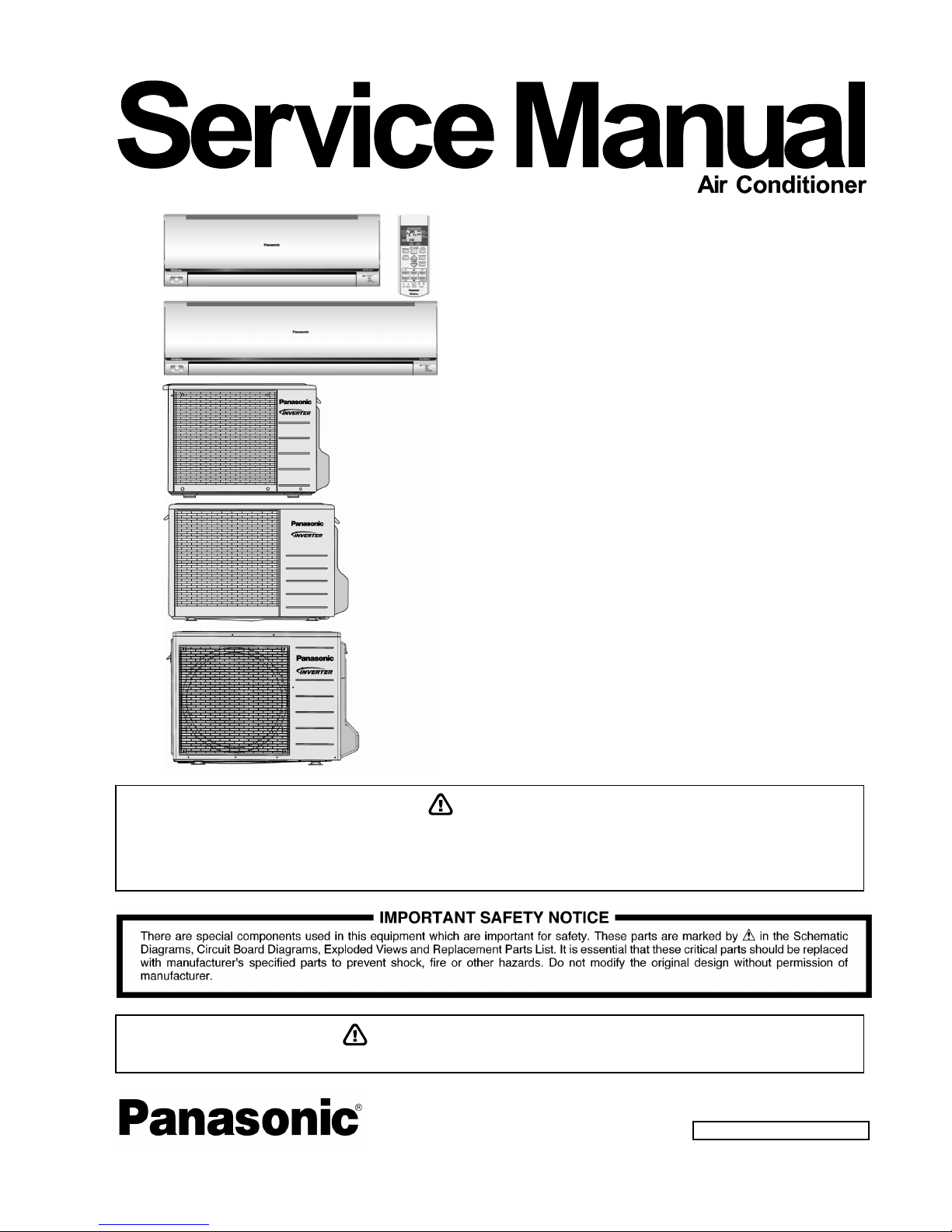
Panasonic CS-PS12PKV, CU-PS18PKV, CU-PS9PKV, CU-PS12PKV, CU-PS24PKV Service Manual
...
© Panasonic Corporation 2013
Order No: PAPAMY1307113CE
Indoor Unit Outdoor Unit
CS-PS9PKV
CS-PS12PKV
CS-PS18PKV
CS-PS24PKV
CU-PS9PKV
CU-PS12PKV
CU-PS18PKV
CU-PS24PKV
Destination
Panama
Columbia
Ecuador
Caribbean Islands
Trinidad & Tobago
PRECAUTION OF LOW TEMPERATURE
In order to avoid frostbit, be assured of no refrigerant leakage during the installation or repairing of refrigerant circuit.
WARNING
This service information is designed for experienced repair technicians only and is not designed for use by the general public.
It does not contain warnings or cautions to advise non-technical individuals of potential dangers in attempting to service a product.
Products powered by electricity should be serviced or repaired only by experienced professional technicians. Any attempt to
service or repair the products dealt with in this service information by anyone else could result in serious injury or death.

2
TABLE OF CONTENTS
1. Safety Precautions ............................................. 3
2. Specification ....................................................... 5
3. Location of Controls and Components ............ 9
3.1 Indoor Unit .................................................... 9
3.2 Outdoor Unit ................................................. 9
3.3 Remote Control ............................................ 9
4. Dimensions ....................................................... 10
4.1 Indoor Unit .................................................. 10
4.2 Outdoor Unit ............................................... 12
5. Refrigeration Cycle Diagram ........................... 14
5.1 CS-PS9PKV CU-PS9PKV
CS-PS12PKV CU-PS12PKV ..................... 14
5.2 CS-PS18PKV CU-PS18PKV
CS-PS24PKV CU-PS24PKV ..................... 15
6. Block Diagram .................................................. 16
6.1 CS-PS9PKV CU-PS9PKV ......................... 16
6.2 CS-PS12PKV CU-PS12PKV ..................... 17
6.3 CS-PS18PKV CU-PS18PKV ..................... 18
6.4 CS-PS24PKV CU-PS24PKV ..................... 19
7. Wiring Connection Diagram ............................ 20
7.1 Indoor Unit .................................................. 20
7.2 Outdoor Unit ............................................... 22
8. Electronic Circuit Diagram .............................. 26
8.1 Indoor Unit .................................................. 26
8.2 Outdoor Unit ............................................... 28
9. Printed Circuit Board ....................................... 32
9.1 Indoor Unit .................................................. 32
9.2 Outdoor Unit ............................................... 35
10. Installation Instruction ..................................... 40
10.1 Select the Best Location ............................. 40
10.2 Indoor Unit .................................................. 41
10.3 Outdoor Unit ............................................... 45
11. Operation Control ............................................. 48
11.1 Basic Function ............................................ 48
11.2 Indoor Fan Motor Operation ....................... 49
11.3 Outdoor Fan Motor Operation .................... 49
11.4 Airflow Direction .......................................... 50
11.5 Timer Control .............................................. 50
11.6 Random Auto Restart Control .................... 51
11.7 Indication Panel .......................................... 51
11.8 ECONAVI & AUTO COMFORT
Operation .................................................... 52
12. Protection Control ............................................ 56
12.1 Restart Control (Time Delay Safety
Control) ....................................................... 56
12.2 30 Seconds Forced Operation ................... 56
12.3 Total Running Current Control ................... 56
12.4 IPM (Power Transistor) Prevention
Control ........................................................ 56
12.5 Low Pressure Prevention Control
(Gas Leakage Detection) ........................... 57
12.6 Compressor Tank Temperature Rise
Protection Control .......................................57
12.7 Low Frequency Protection Control 1 ..........57
12.8 Low Frequency Protection Control 2 ..........57
12.9 Outdoor Air Temperature Control ...............57
12.10 Cooling Overload Control ...........................58
12.11 Freeze Prevention Control .........................58
12.12 Freeze Prevention Control 2 ......................58
12.13 Dew Prevention Control .............................58
12.14 Odor Cut Control ........................................58
13. Servicing Mode .................................................59
13.1 Auto Off/On Button .....................................59
13.2 Remote Control Button ...............................60
14. Troubleshooting Guide ....................................61
14.1 Refrigeration Cycle System ........................61
14.2 Breakdown Self Diagnosis Function ...........63
14.3 Error Code Table ........................................64
14.4 Troubleshooting Flowchart .........................65
15. Disassembly and Assembly Instructions ......87
15.1 CS-PS9/12PKV ..........................................87
15.2 CS-PS18/24PKV ........................................91
16. Technical Data ..................................................95
16.1 Operation Characteristics ...........................95
17. Exploded View and Replacement Parts
List .................................................................. 103
17.1 Indoor Unit ............................................... 103
17.2 Outdoor Unit ............................................ 109
3
CAUTION
WARNING
WARNING
1. Safety Precautions
• Read the following “SAFETY PRECAUTIONS” carefully before perform any servicing.
• Electrical work must be installed or serviced by a licensed electrician. Be sure to use the correct rating of the
power plug and main circuit for the model installed.
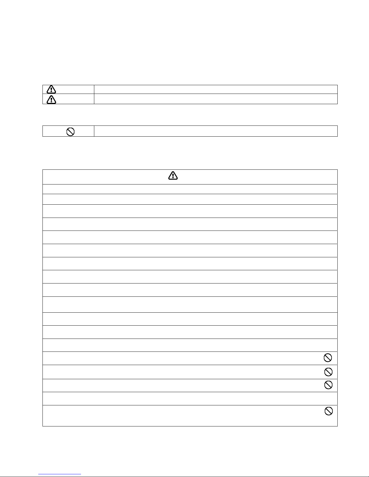
• The caution items stated here must be followed because these important contents are related to safety. The
meaning of each indication used is as below. Incorrect installation or servicing due to ignoring of the instruction
will cause harm or damage, and the seriousness is classified by the following indications.
This indication shows the possibility of causing death or serious injury
This indication shows the possibility of causing injury or damage to properties.
• The items to be followed are classified by the symbols:
• Carry out test run to confirm that no abnormality occurs after the servicing. Then, explain to user the operation,
care and maintenance as stated in instructions. Please remind the customer to keep the operating instructions for
future reference.
1. Do not modify the machine, part, material during repairing service.
2. If wiring unit is supplied as repairing part, do not repair or connect the wire even only partial wire break. Exchange the whole wiring unit.
3. Do not wrench the fasten terminal. Pull it out or insert it straightly.
4. Engage dealer or specialist for installation and servicing. If installation of servicing done by the user is defective, it will cause water leakage,
electrical shock or fire.
5. Install according to this installation instructions strictly. If installation is defective, it will cause water leakage, electric shock or fire.
6. Use the attached accessories parts and specified parts for installation and servicing. Otherwise, it will cause the set to fall, water leakage, fire
or electrical shock.
7. Install at a strong and firm location which is able to withstand the set’s weight. If the strength is not enough or installation is not properly done,
the set will drop and cause injury.
8. For electrical work, follow the local national wiring standard, regulation and the installation instruction. An independent circuit and single outlet
must be used. If electrical circuit capacity is not enough or defect found in electrical work, it will cause electrical shock or fire.
9. This equipment is strongly recommended to install with Earth Leakage Circuit Breaker (ELCB) or Residual Current Device (RCD). Otherwise, it
may cause electrical shock and fire in case equipment breakdown or insulation breakdown.
10. Do not use joint cable for indoor / outdoor connection cable. Use the specified indoor / outdoor connection cable, refer to installation instruction
CONNECT THE CABLE TO THE INDOOR UNIT and connect tightly for indoor / outdoor connection. Clamp the cable so that no external force
will be acted on the terminal. If connecting or fixing is not perfect, it will cause heat up or fire at the connection.
11. Wire routing must be properly arranged so that control board cover is fixed properly. If control board cover is not fixed perfectly, it will cause
heat-up or fire at the connection point of terminal, fire or electrical shock.
12. When install or relocate air conditioner, do not let any substance other than the specified refrigerant, eg.air etc. mix into refrigeration cycle
(piping). (Mixing of air etc. will cause abnormal high pressure in refrigeration cycle and result in explosion, injury etc.).
13. Do not install outdoor unit near handrail of veranda. When installing air-conditioner unit at veranda of high rise building, child may
climb up to outdoor unit and cross over the handrail and causing accident.
14. This equipment must be properly earthed. Earth line must not be connected to gas pipe, water pipe, earth of lightning rod and
telephone. Otherwise, it may cause electric shock in case equipment breakdown or insulation breakdown.
15. Keep away from small children, the thin film may cling to nose and mouth and prevent breathing.
16. Do not use unspecified cord, modified cord, joint cord or extension cord for power supply cord. Do not share the single outlet with
other electrical appliances. Poor contact, poor insulation or over current will cause electrical shock or fire.
17. Tighten the flare nut with torque wrench according to specified method. If the flare nut is over-tightened, after a long period, the flare may
break and cause refrigerant gas leakage.
18. For R410A model, use piping, flare nut and tools which is specified for R410A refrigerant. Using of existing (R22) piping, flare nut and
tools may cause abnormally high pressure in the refrigerant cycle (piping), and possibly result in explosion and injury.
Thickness or copper pipes used with R410A must be more than 0.8 mm. Never use copper pipes thinner than 0.8 mm.
It is desirable that the amount of residual oil less than 40 mg/10 m.
This symbol denotes item that is PROHIBITED from doing.
4
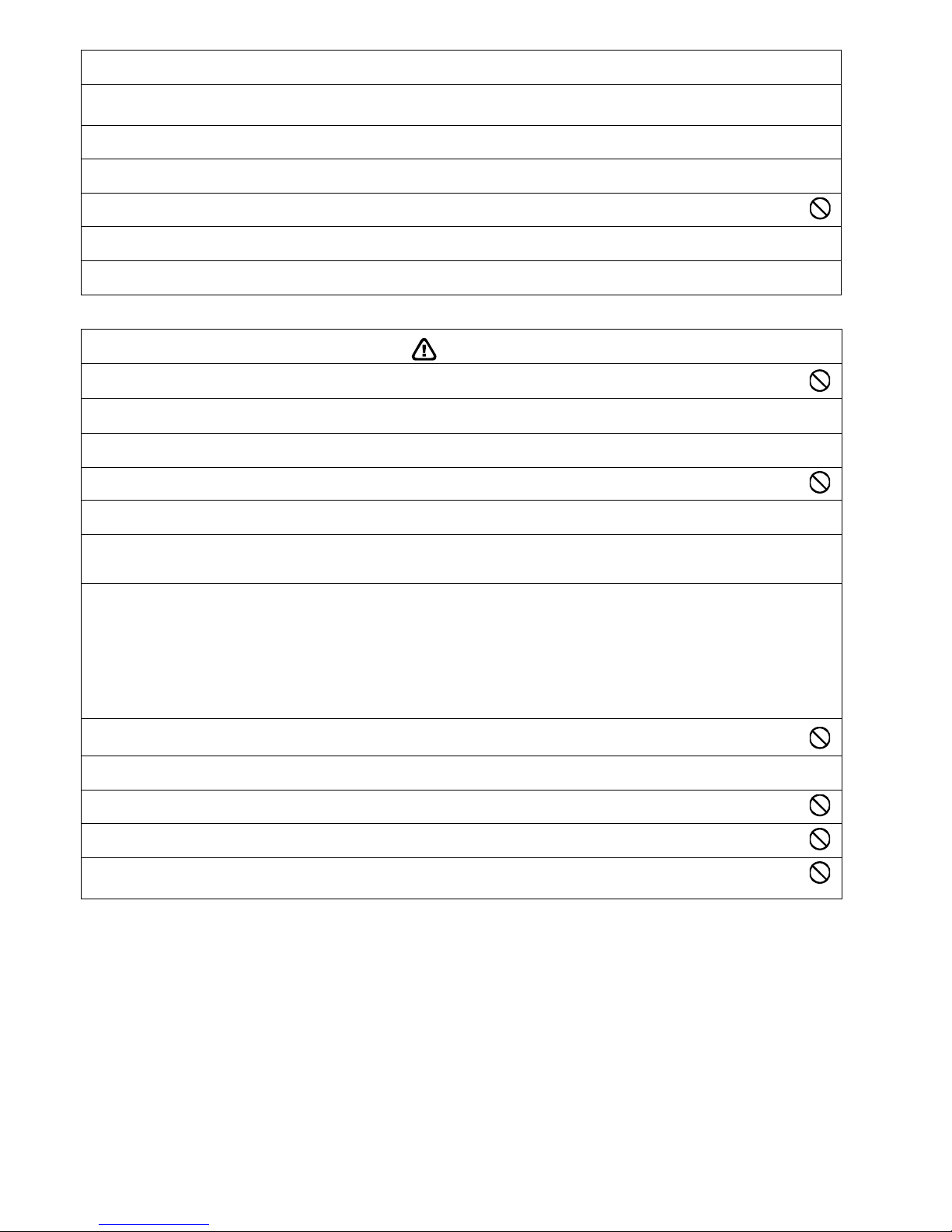
CAUTION
19. During installation, before run the compressor, confirm the refrigerant pipes are fixed. Operation of compressor without fixing the piping,
setting the valves at open condition, a burst may occur and cause injury.
20. During pump down operation, stop the compressor before remove the refrigerant piping. (Removal of refrigeration piping while compressor is
operating and valves are opened condition will cause suck-in of air, abnormal high pressure in refrigeration cycle and result in explosion, injury
etc.)
21. After completion of installation or service, confirm there is no leakage or refrigerant gas. It may generate toxic gas when the refrigerant
contacts with fire.
22. Ventilate if there is refrigerant gas leakage during operation. It may cause toxic gas when refrigerant contacts with fire.
23. Do not insert your fingers or other objects into the unit, high speed rotating fan may cause injury.
24. Must not use other parts except original parts describe in catalog and manual.
25. Using of refrigerant other than the specified type may cause product damage, burst and injury etc.
1. Do not install the unit at place where leakage of flammable gas may occur. In case gas leaks and accumulates at surrounding of the
unit, it may cause fire.
2. Carry out drainage piping as mentioned in installation instructions. If drainage is not perfect, water may enter the room and damage
the furniture.
3. Tighten the flare nut with torque wrench according to specified method. If the flare nut is over-tightened, after a long period, the flare
may break and cause refrigerant gas leakage.
4. Do not touch outdoor unit air inlet and aluminium fin. It may cause injury.
5. Select an installation location which is easy for maintenance.
6. Pb free solder has a higher melting point than standard solder; typically the melting point is 50°F – 70°F (30°C – 40°C) higher. Please use
a high temperature solder iron. In case of the soldering iron with temperature control, please set it to 700 ± 20°F (370 ± 10°C).
Pb free solder will tend to splash when heated too high (about 1100°F / 600°C).
7. Power supply connection to the room air conditioner.
Use power supply cord 3 x 1.5 mm
2
(1.0 ~ 1.5HP) or 3 x 2.5 mm2 (2.0 ~ 2.5HP) type designation 245 IEC 57 or heavier cord.
Connect the power supply cord of the air conditioner to the mains using one of the following method.
Power supply point should be in easily accessible place for power disconnection in case of emergency.
In some countries, permanent connection of this air conditioner to the power supply is prohibited.
i. Power supply connection to the receptacle using power plug.
Use an approved 15/16A (1.0 ~ 1.5HP) or 16A (2.0HP) or 20A (2.5HP) power plug with earth pin for the connection to the socket.
ii. Power supply connection to a circuit breaker for the permanent connection.
Use an approved 16A (1.0 ~ 2.0HP) or 20A (2.5HP) circuit breaker for the permanent connection. It must be a double pole switch with a
minimum 3.0 mm contact gap.
8. Do not release refrigerant during piping work for installation, servicing, reinstallation and during repairing a refrigerant parts. Take
care of the liquid refrigerant, it may cause frostbite.
9. Installation or servicing work: It may need two people to carry out the installation or servicing work.
10. Do not install this appliance in a laundry room or other location where water may drip from the ceiling, etc.
11. Do not sit or step on the unit, you may fall down accidentally.
12. Do not touch the sharp aluminum fins or edges of metal parts.
If you are required to handle sharp parts during installation or servicing, please wear hand glove.
Sharp parts may cause injury
5
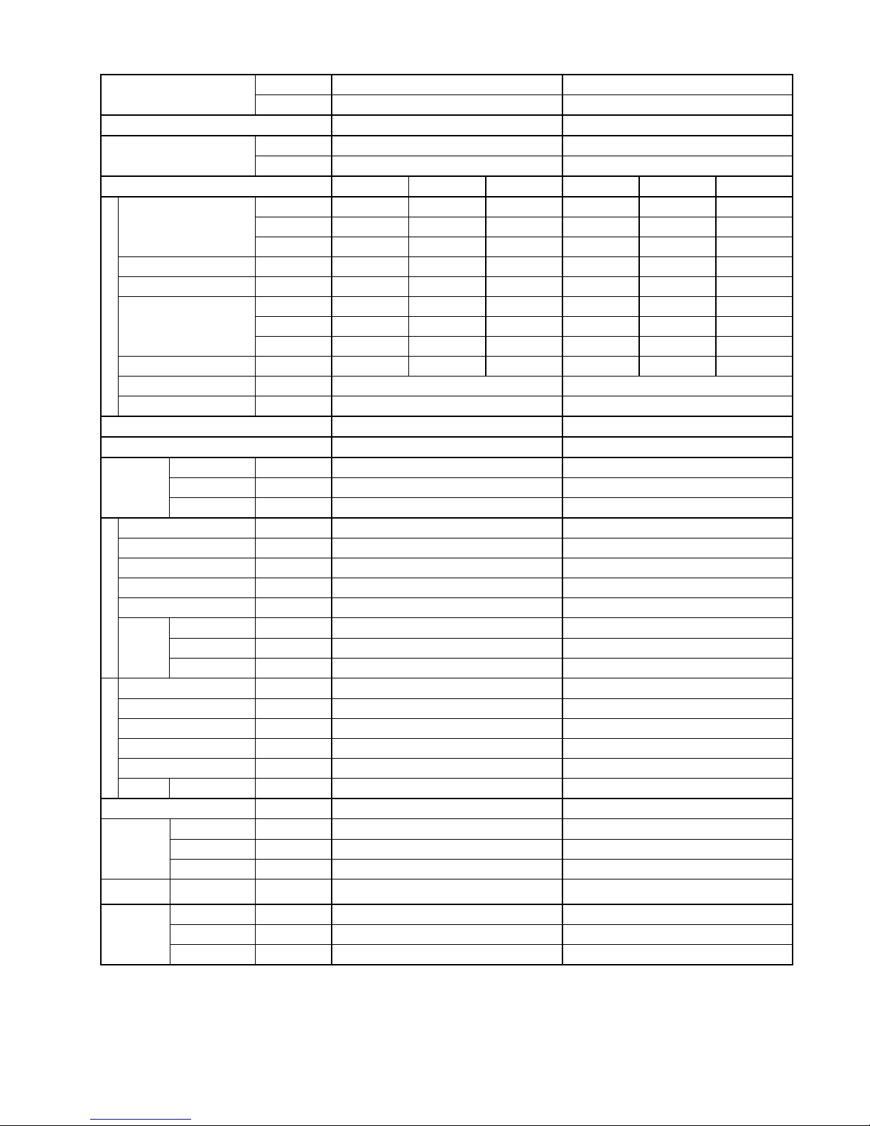
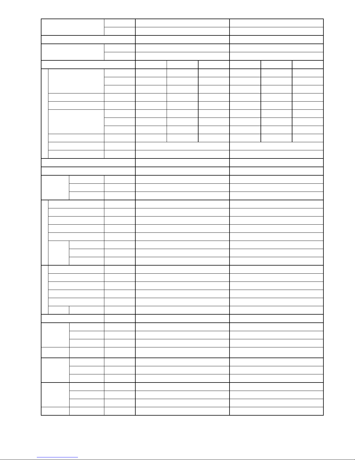
2. Specification
Model
Indoor CS-PS9PKV CS-PS12PKV
Outdoor CU-PS9PKV CU-PS12PKV
Performance Test Condition JIS JIS
Power Supply
Phase, Hz Single, 60 Single, 60
V 220 220
Min. Mid. Max. Min. Mid. Max.
Cooling
Capacity
kW 0.84 2.54 3.15 0.92 3.06 4.00
BTU/h 2860 8660 10700 3140 10400 13600
kJ/h 3020 9140 11340 3310 11020 14400
Running Current A - 3.4 - - 4.0 -
Input Power W 225 680 885 260 820 1.17k
EER
W/W 3.73 3.74 3.56 3.54 3.73 3.42
BTU/hW 12.71 12.74 12.09 12.08 12.68 11.62
kJ/hW 13.42 13.44 12.81 12.73 13.44 12.31
Power Factor % - 91 - - 93 -
Indoor Noise (H / L / QLo) dB-A 36 / 26 / - 38 / 28 / -
Outdoor Noise (H / L / QLo) dB-A 46 / - / - 47 / - / -
Max Current (A) / Max Input Power (W) 6.2 / 1.12k 7.4 / 1.43k
Starting Current (A) 3.4 4.0
Compressor
Type Hermetic Motor / Rotary Hermetic Motor / Rotary
Motor Type Brushless (6 poles) Brushless (6 poles)
Output Power W 650 650
Indoor Fan
Type Cross-flow fan Cross-flow fan
Material ASG20K1 ASG20K1
Motor Type AC / Induction (4 poles) AC / Induction (4 poles)
Input Power W 51.0 51.0
Output Power W 16 16
Speed
Lo rpm 680 720
Me rpm 840 890
Hi rpm 1000 1060
Outdoor Fan
Type Propeller Propeller
Material PP Resin PP Resin
Motor Type AC / Induction (6 poles) AC / Induction (6 poles)
Input Power W - -
Output Power W 20 28
Speed Hi rpm 770 790
Moisture Removal L/h (Pt/h) 1.6 (3.4) 1.7 (3.6)
Indoor Airflow
Lo m
3
/min (ft3/m) 6.3 (222) 6.8 (240)
Me m3/min (ft3/m) 8.2 (290) 8.8 (311)
Hi m3/min (ft3/m) 10.1 (355) 10.9 (385)
Outdoor
Airflow
Hi m
3
/min (ft3/m) 22.0 (780) 31.2 (1100)
Refrigeration
Cycle
Control Device Capillary Tube Capillary Tube
Refrigerant Oil cm3 FV50S (320) FV50S (320)
Refrigerant Type g (oz) R410A, 740 (26.1) R410A, 690 (24.4)

6
Dimension
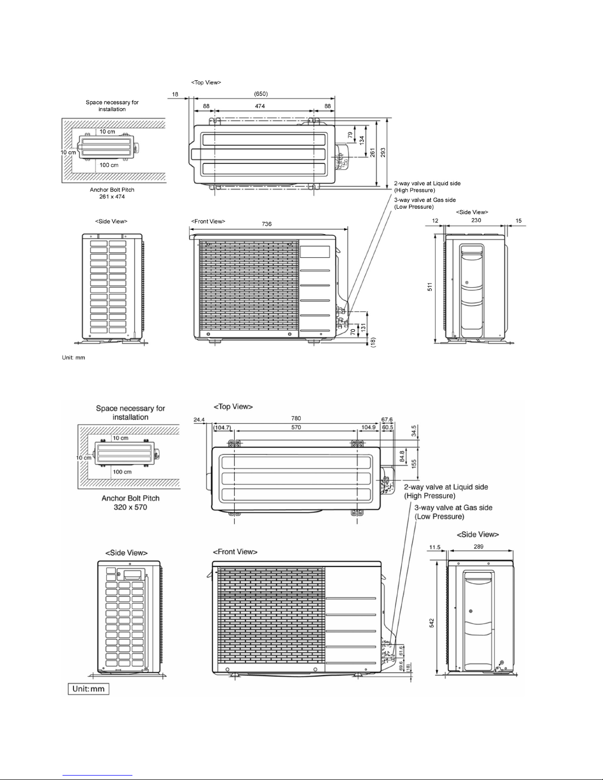
Height(I/D / O/D) mm (inch) 290 (11-7/16) / 511 (20-1/8) 290 (11-7/16) / 542 (21-11/32)
Width (I/D / O/D) mm (inch) 870 (34-9/32) / 650 (25-19/32) 870 (34-9/32) / 780 (30-23/32)
Depth (I/D / O/D) mm (inch) 214 (8-7/16) / 230 (9-1/16) 214 (8-7/16) / 289 (11-13/32)
Weight Net (I/D / O/D) kg (lb) 9 (20) / 23 (51) 9 (20) / 29 (64)
Piping
Pipe Diameter (Liquid / Gas) mm (inch) 6.35 (1/4) / 9.52 (3/8) 6.35 (1/4) / 12.7 (1/2)
Standard length m (ft) 7.5 (24.6) 7.5 (24.6)
Length range (min – max) m (ft) 3 (9.8) ~ 15 (49.2) 3 (9.8) ~ 15 (49.2)
I/D & O/D Height different m (ft) 5.0 (16.4) 5.0 (16.4)
Additional Gas Amount g/m (oz/ft) 15 (0.2) 15 (0.2)
Length for Additional Gas m (ft) 7.5 (24.6) 7.5 (24.6)
Drain Hose
Inner Diameter mm 16 16
Length mm 550 550
Indoor Heat
Exchanger
Fin Material Aluminium (Pre coated) Aluminium (Pre coated)
Fin Type Slit Fin Slit Fin
Row x Stage x FPI 2 x 15 x 17 2 x 15 x 17
Size (W x H x L) mm 610 x 315 x 25.4 610 x 315 x 25.4
Outdoor
Heat
Exchanger
Fin Material Aluminium (Blue coated) Aluminium (Blue coated)
Fin Type Slit Fin Louver Fin
Row x Stage x FPI 2 x 23 x 17 1 x 20 x 19
Size (W x H x L) mm 25.4 x 483 x 553.4:573.4 22 x 508 x 708
Air Filter
Material Polypropelene Polypropelene
Type One-touch One-touch
Power Supply Indoor Indoor
Power Supply Cord A 10 10
Thermostat - -
Protection Device - -
DRY BULB WET BULB DRY BULB WET BULB
Indoor Operation Range
Maximum °C 32 23 32 23
Minimum °C 16 11 16 11
Outdoor Operation Range
Maximum °C 43 26 43 26
Minimum °C 16 11 16 11
1. Cooling capacities are based on indoor temperature of 27°C DRY BULB (80.6°F DRY BULB), 19.0°C WET BULB (66°F WET BULB) and
outdoor air temperature of 35°C DRY BULB (95°F DRY BULB), 24°C WET BULB (75.2°F WET BULB)
7
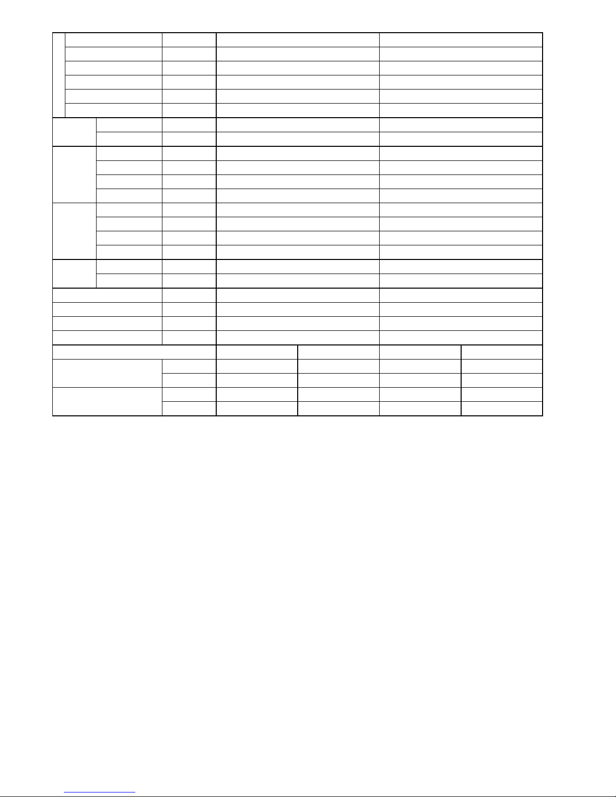
Model
Indoor CS-PS18PKV CS-PS24PKV
Outdoor CU-PS18PKV CU-PS24PKV
Performance Test Condition JIS JIS
Power Supply
Phase, Hz Single, 60 Single, 60
V 220 220
Min. Mid. Max. Min. Mid. Max.
Cooling
Capacity
kW 1.10 5.15 6.00 1.12 5.87 6.70
BTU/h 3750 17600 20500 3820 20000 22800
kJ/h 3960 18540 21600 4030 21130 24120
Running Current A - 7.0 - - 8.5 -
Input Power W 290 1.49k 1.74k 320 1.83k 2.10k
EER
W/W 3.79 3.46 3.45 3.50 3.21 3.19
BTU/hW 12.93 11.81 11.78 11.94 10.93 10.86
kJ/hW 13.66 12.44 12.41 12.59 11.55 11.49
Power Factor % - 97 - - 98 -
Indoor Noise (H / L / QLo) dB-A 45 / 36 / - 46 / 37 / -
Outdoor Noise (H / L / QLo) dB-A 49 / - / - 49 / - / -
Max Current (A) / Max Input Power (W) 9.5 / 2.07k 12.5 / 2.50k
Starting Current (A) 7.0 8.5
Compressor
Type Hermetic Motor / Rotary Hermetic Motor / Rotary
Motor Type Induction (6-poles) Induction (4-poles)
Output Power W 900 900
Indoor Fan
Type Cross-flow fan Cross-flow fan
Material ASG30K1 ASG30K1
Motor Type DC / Transistor (8-poles) DC / Transistor (8-poles)
Input Power W 94.8 94.8
Output Power W 40 40
Speed
Lo rpm 930 960
Me rpm 1110 1140
Hi rpm 1300 1330
Outdoor Fan
Type Propeller Propeller
Material PP Resin PP Resin
Motor Type AC / Induction (6-poles) AC / Induction (6-poles)
Input Power W - -
Output Power W 40 66
Speed Hi rpm 840 760
Moisture Removal L/h (Pt/h) 2.9 (6.1) 3.2 (6.8)
Indoor Airflow
Lo m
3
/min (ft3/m) 12.5 (441) 13.2 (466)
Me m3/min (ft3/m) 15.2 (537) 16.0 (565)
Hi m3/min (ft3/m) 18.1 (640) 18.9 (670)
Outdoor
Airflow
Hi m
3
/min (ft3/m) 31.2 (1100) 46.0 (1620)
Refrigeration
Cycle
Control Device Expansion Valve Capillary Tube
Refrigerant Oil cm3 FV50S (450) FV50S (450)
Refrigerant Type g (oz) R410A, 1.04k (36.7) R410A, 900 (31.8)
Dimension
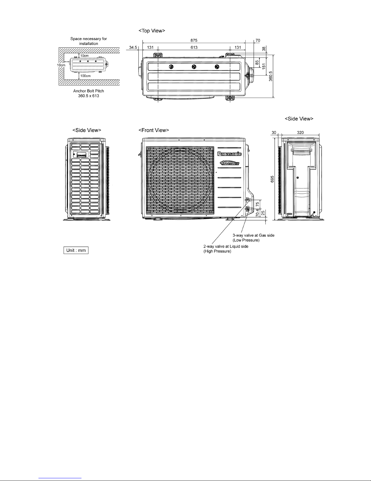
Height(I/D / O/D) mm (inch) 290 (11-7/16) / 542 (21-11/32) 290 (11-7/16) / 695 (27-3/8)
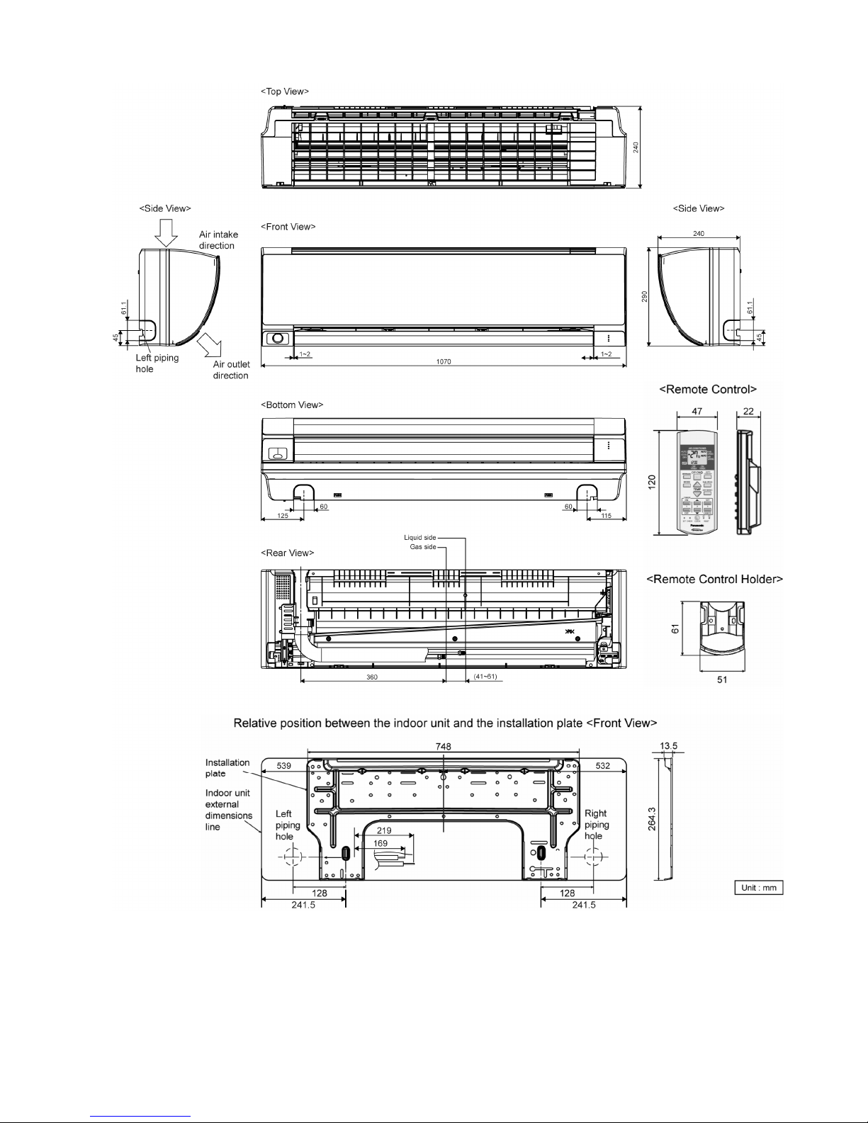
Width (I/D / O/D) mm (inch) 1070 (42-5/32) / 780 (30-23/32) 1070 (42-5/32) / 875 (34-15/32)
Depth (I/D / O/D) mm (inch) 240 (9-15/32) / 289 (11-13/32) 240 (9-15/32) / 320 (12-5/8)
Weight Net (I/D / O/D) kg (lb) 12 (26) / 32 (71) 12 (26) / 45 (99)
8
Piping
Pipe Diameter (Liquid / Gas) mm (inch) 6.35 (1/4) / 12.70 (1/2) 6.35 (1/4) / 15.88 (5/8)
Standard length m (ft) 5.0 (16.4) 5.0 (16.4)
Length range (min – max) m (ft) 3 (9.8) ~ 20 (65.6) 3 (9.8) ~ 20 (65.6)
I/D & O/D Height different m (ft) 15 (49.2) 15 (49.2)
Additional Gas Amount g/m (oz/ft) 15 (0.2) 20 (0.2)
Length for Additional Gas m (ft) 10 (32.8) 10 (32.8)
Drain Hose
Inner Diameter mm 16 16
Length mm 550 550
Indoor Heat
Exchanger
Fin Material Aluminium (Pre coated) Aluminium (Pre coated)
Fin Type Slit Fin Slit Fin
Row x Stage x FPI 2 x 15 x 17 2 x 15 x 17
Size (W x H x L) mm 810 x 315 x 25.4 810 x 315 x 25.4
Outdoor
Heat
Exchanger
Fin Material Aluminium (Blue coated) Aluminium (Blue coated)
Fin Type Slit Fin Slit Fin
Row x Stage x FPI 2 x 24 x 17 1 x 31 x 19
Size (W x H x L) mm 25.4 x 504 x 693.4:713.4 12.7 x 651.0 x 868.0
Air Filter
Material Polypropelene Polypropelene
Type One-touch One-touch
Power Supply Indoor Indoor
Power Supply Cord A 15 20
Thermostat - -
Protection Device - -
DRY BULB WET BULB DRY BULB WET BULB
Indoor Operation Range
Maximum °C 32 23 32 23
Minimum °C 16 11 16 11
Outdoor Operation Range
Maximum °C 43 26 43 26
Minimum °C 16 11 16 11
1. Cooling capacities are based on indoor temperature of 27°C DRY BULB (80.6°F DRY BULB), 19.0°C WET BULB (66°F WET BULB) and
outdoor air temperature of 35°C DRY BULB (95°F DRY BULB), 24°C WET BULB (75.2°F WET BULB)
9
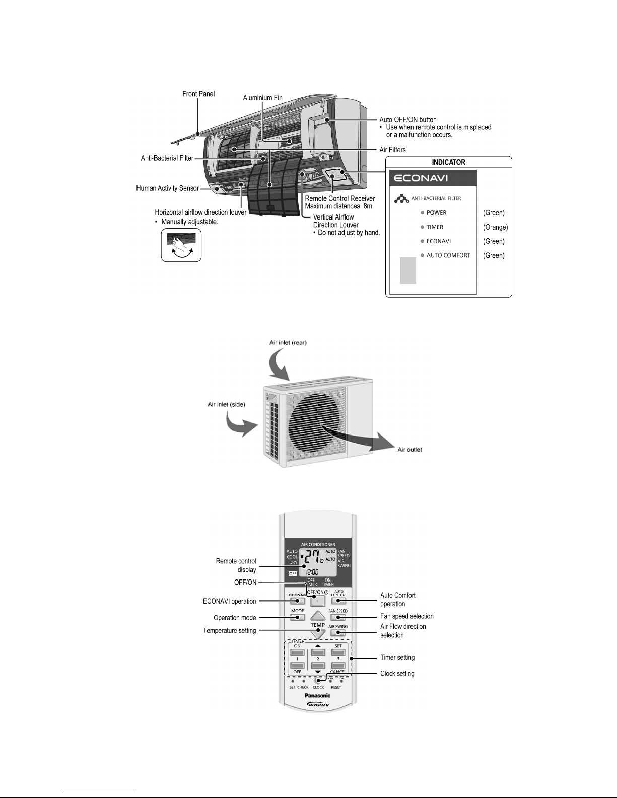
3. Location of Controls and Components
3.1 Indoor Unit
3.2 Outdoor Unit
3.3 Remote Control
10
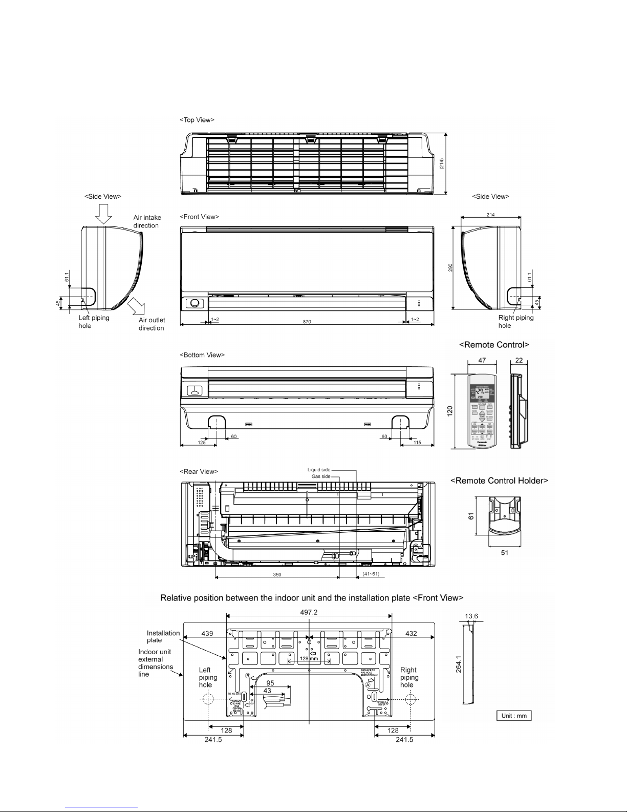
4. Dimensions
4.1 Indoor Unit
4.1.1 CS-PS9PKV CS-PS12PKV
11
4.1.2 CS-PS18PKV CS-PS24PKV
12
4.2 Outdoor Unit
4.2.1 CU-PS9PKV
4.2.2 CU-PS12PKV CU-PS18PKV
13
4.2.3 CU-PS24PKV
14
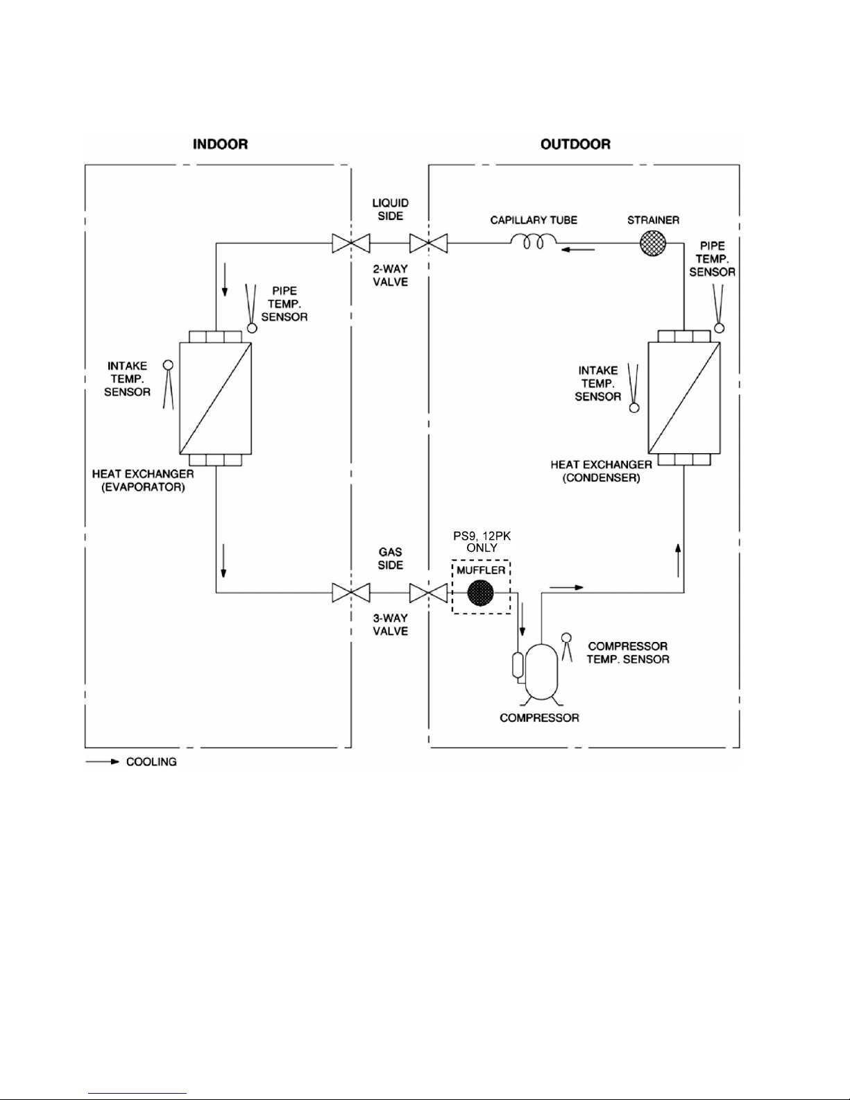
5. Refrigeration Cycle Diagram
5.1 CS-PS9PKV CU-PS9PKV CS-PS12PKV CU-PS12PKV
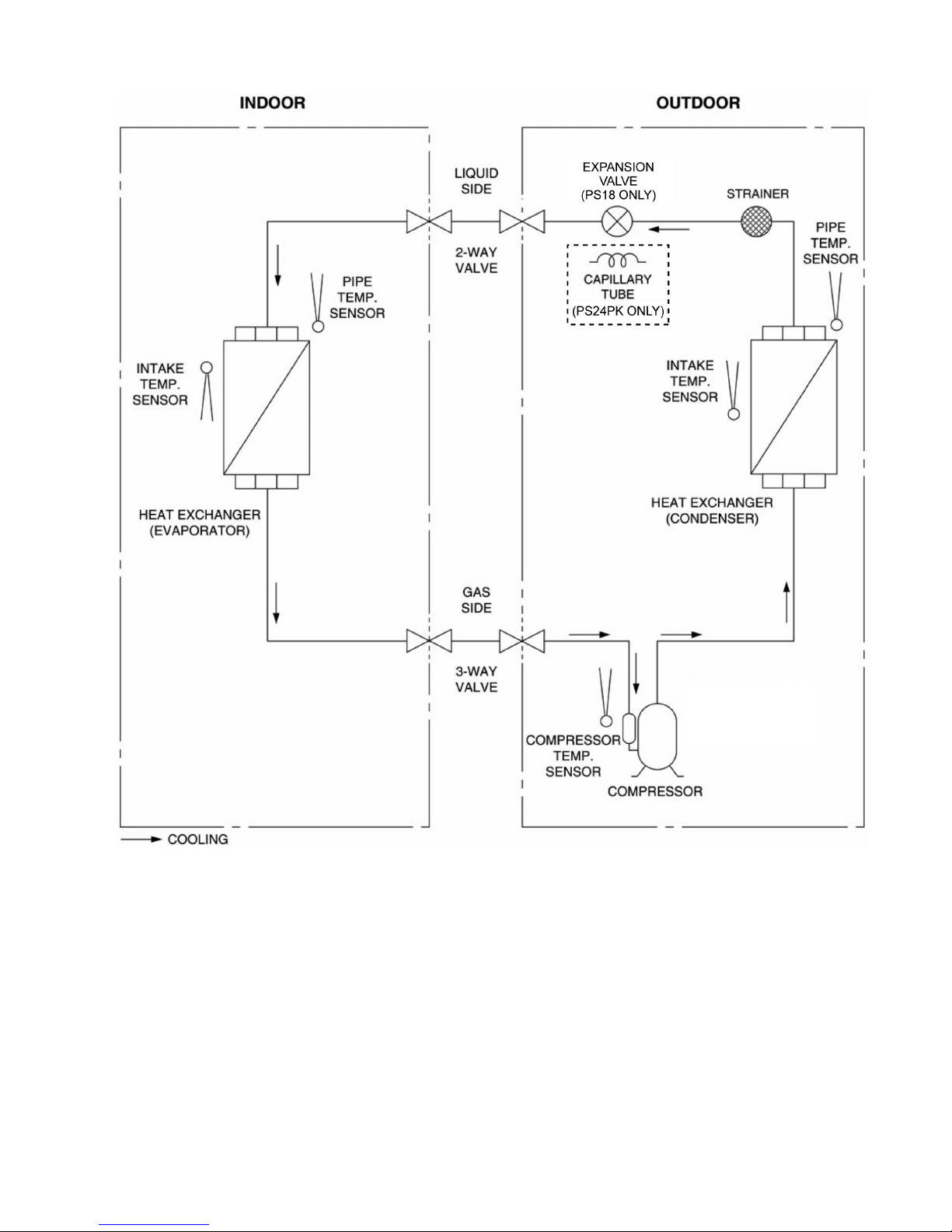
15
5.2 CS-PS18PKV CU-PS18PKV CS-PS24PKV CU-PS24PKV
16
6. Block Diagram
6.1 CS-PS9PKV CU-PS9PKV
17
6.2 CS-PS12PKV CU-PS12PKV
18
6.3 CS-PS18PKV CU-PS18PKV
19
6.4 CS-PS24PKV CU-PS24PKV
20
7. Wiring Connection Diagram
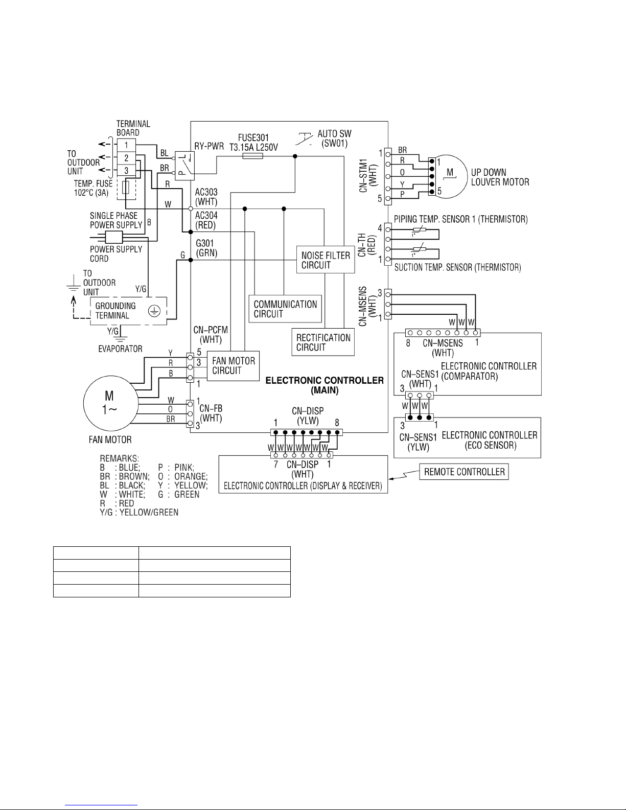
7.1 Indoor Unit
7.1.1 CS-PS9PKV CS-PS12PKV
Resistance of Fan Motor Windings
MODEL CS-PS9PKV / CS-PS12PKV
CONNECTION CWA921443
YELLOW-BLUE 382.0 Ω
RED-YELLOW 226.8 Ω
21
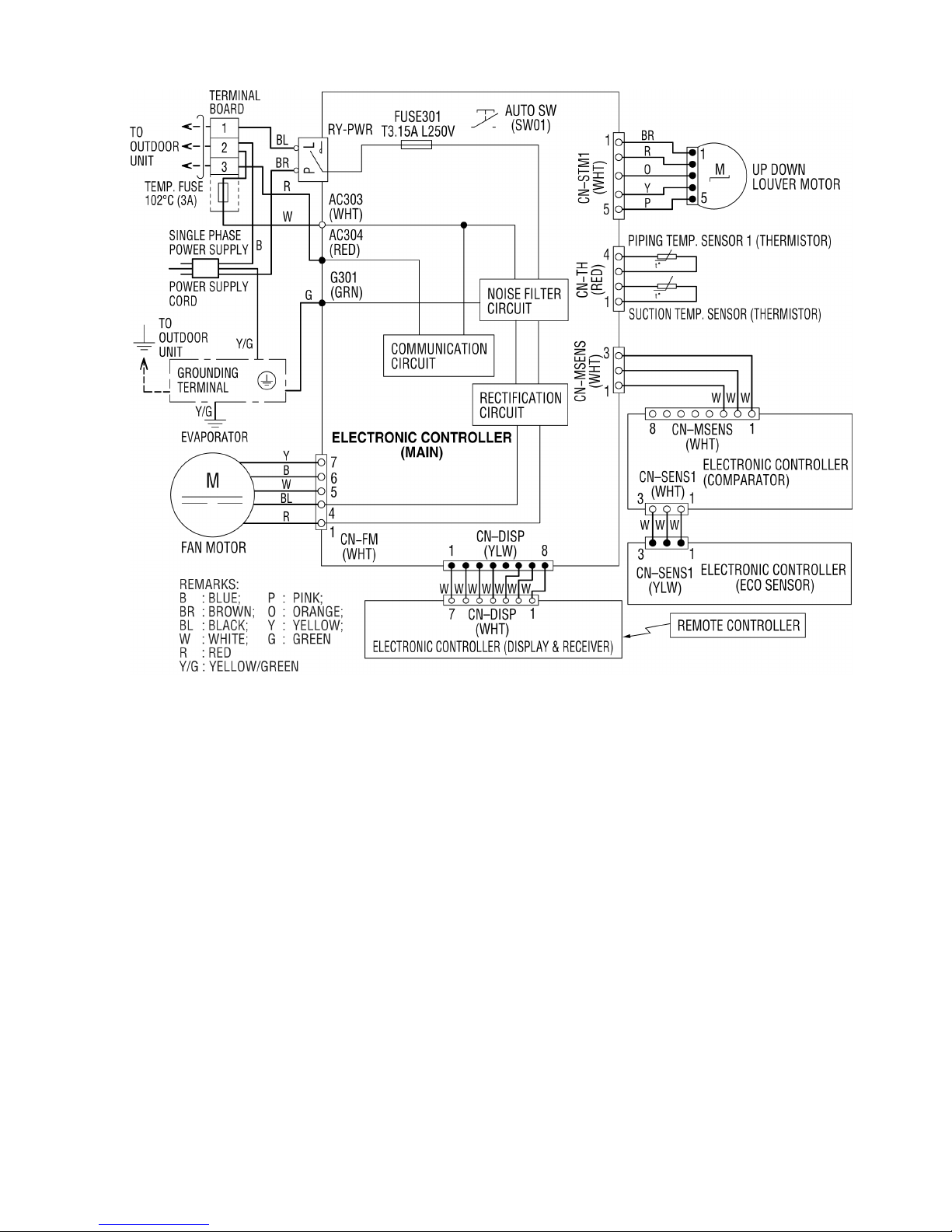
7.1.2 CS-PS18PKV CS-PS24PKV
22
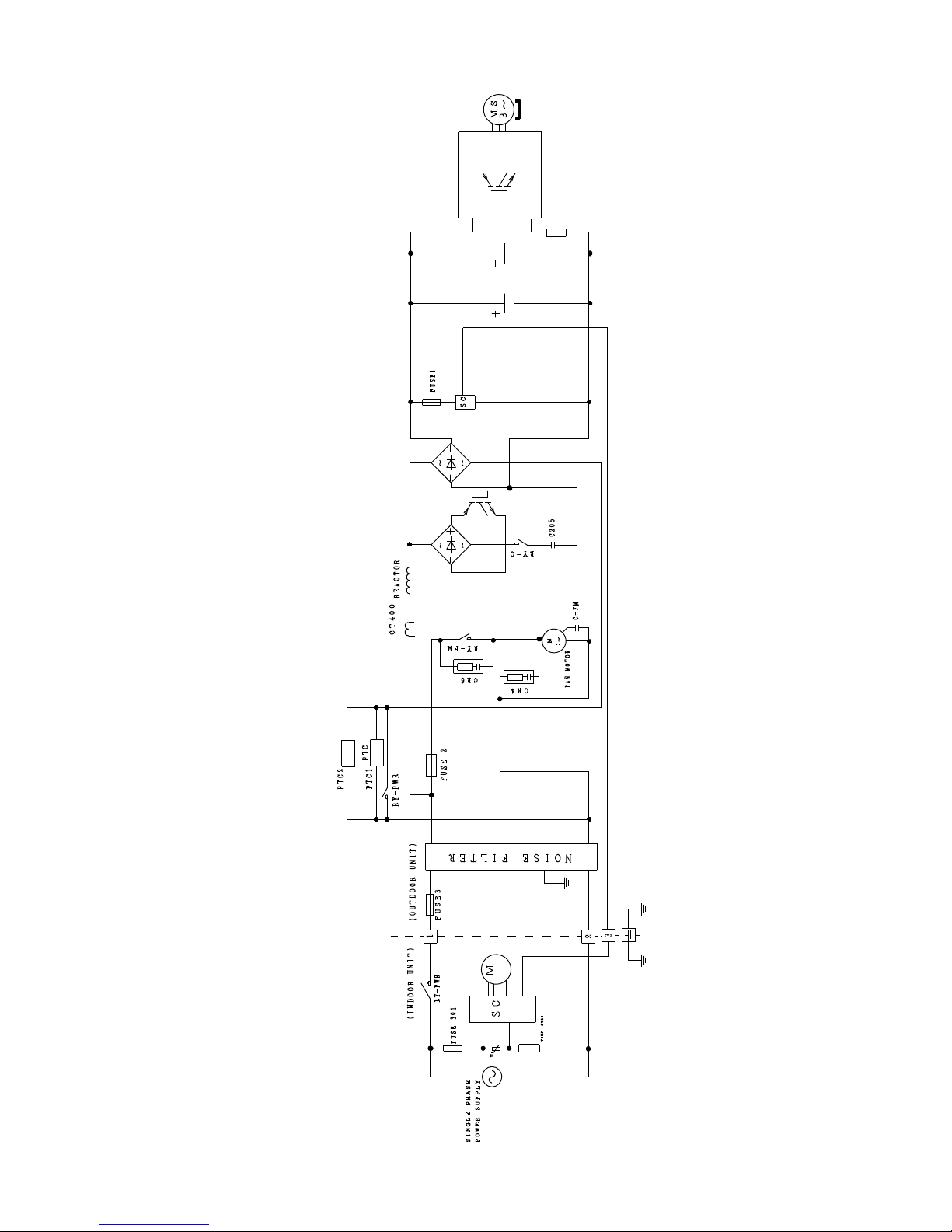
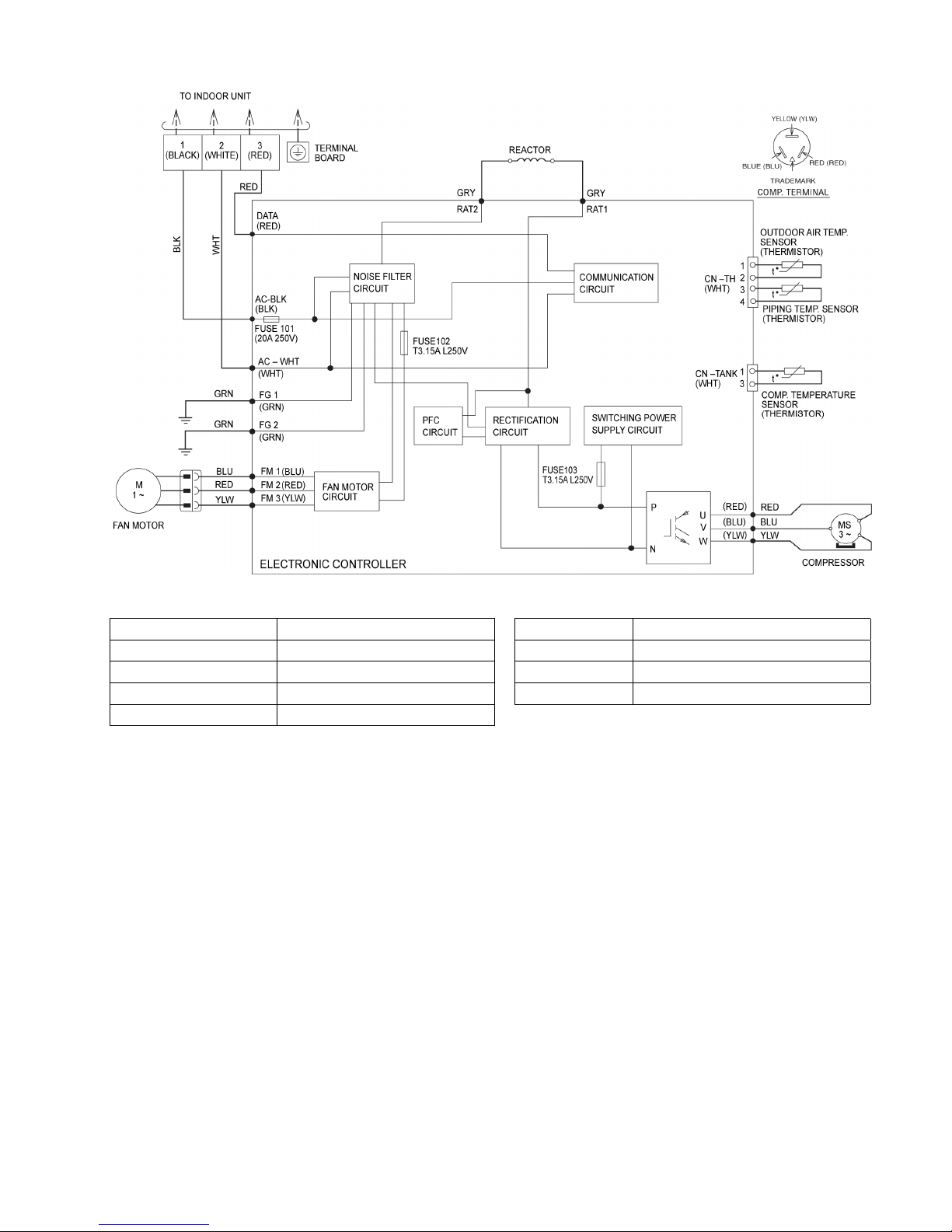
7.2 Outdoor Unit
7.2.1 CU-PS9PKV
Resistance of Compressor Windings
Resistance of Fan Motor Windings
MODEL CU-PS9PKV MODEL CU-PS9PKV
CONNECTION 5RS092XCE21 CONNECTION CWA951734
U-V 1.152Ω YELLOW-BLUE 338.0 Ω
U-W 1.152Ω RED-YELLOW 180.0 Ω
V-W 1.152Ω
23
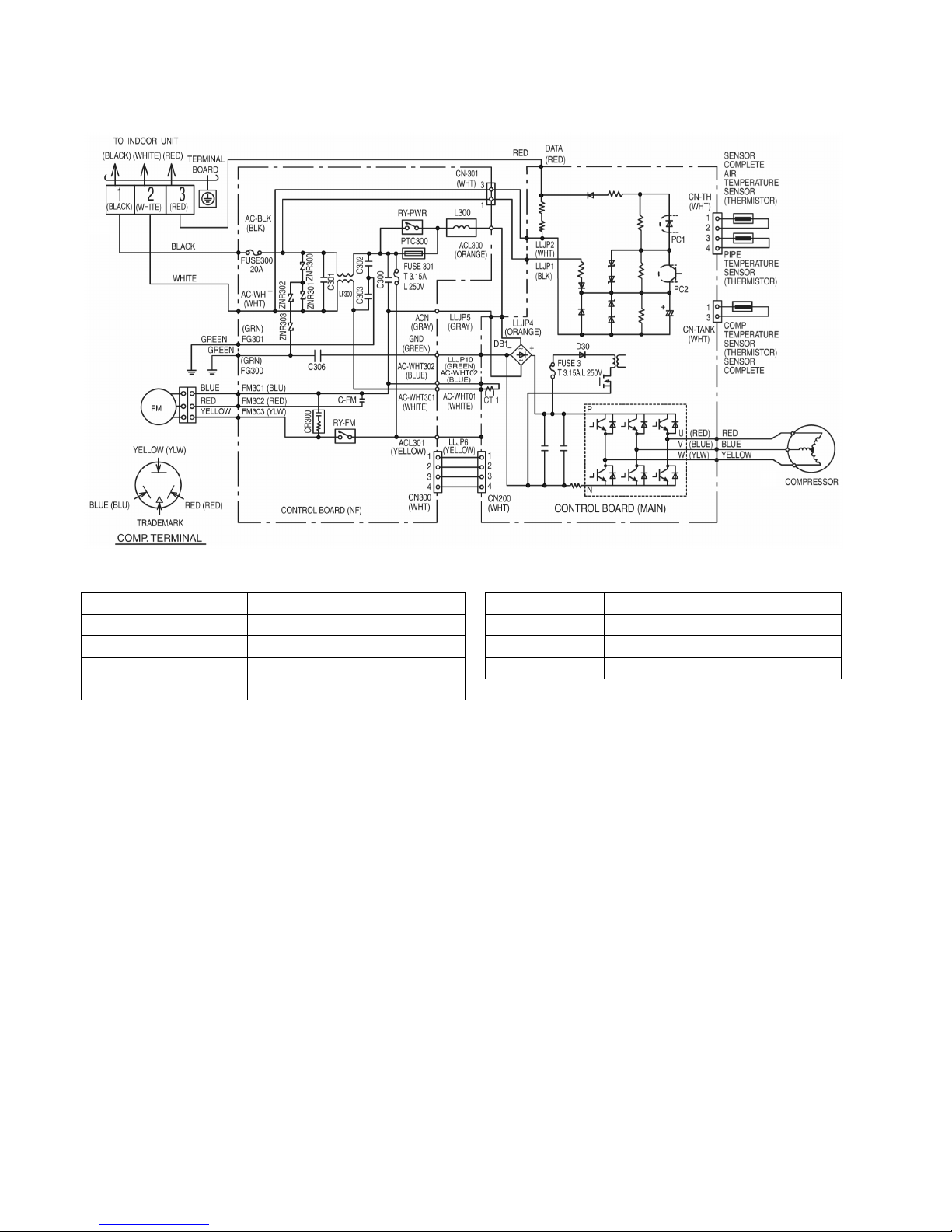
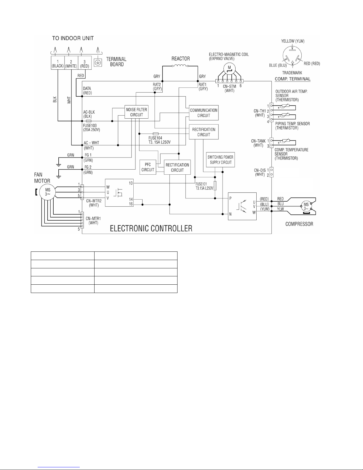
7.2.2 CU-PS12PKV
Resistance of Compressor Windings
Resistance of Fan Motor Windings
MODEL CU-PS12PKV MODEL CU-PS12PKV
CONNECTION 5RS092XCD21 CONNECTION CWA951466
U-V 1.152Ω YELLOW-BLUE 262.7 Ω
U-W 1.152Ω RED-YELLOW 271.0 Ω
V-W 1.152Ω
24
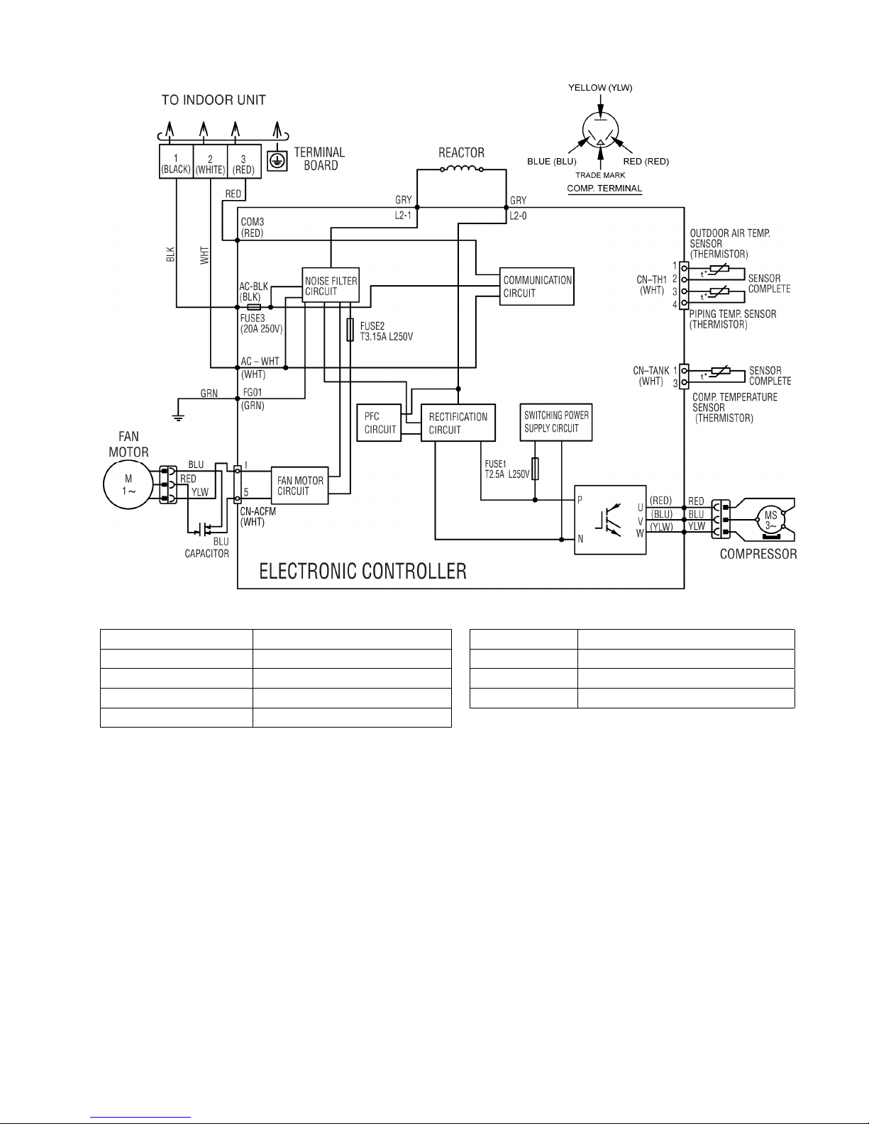
7.2.3 CU-PS18PKV
Resistance of Compressor Windings
MODEL CU-PS18PKV
CONNECTION 5RD132XDA21
U-V 1.152Ω
U-W 1.152Ω
V-W 1.152Ω
25
7.2.4 CU-PS24PKV
Resistance of Compressor Windings
Resistance of Fan Motor Windings
MODEL CU-PS24PKV MODEL CU-PS24PKV
CONNECTION 5RD132XBA21 CONNECTION CWA951762
U-V 1.897Ω YELLOW-BLUE 75.0 Ω
U-W 1.907Ω RED-YELLOW 74.0 Ω
V-W 1.882Ω
26
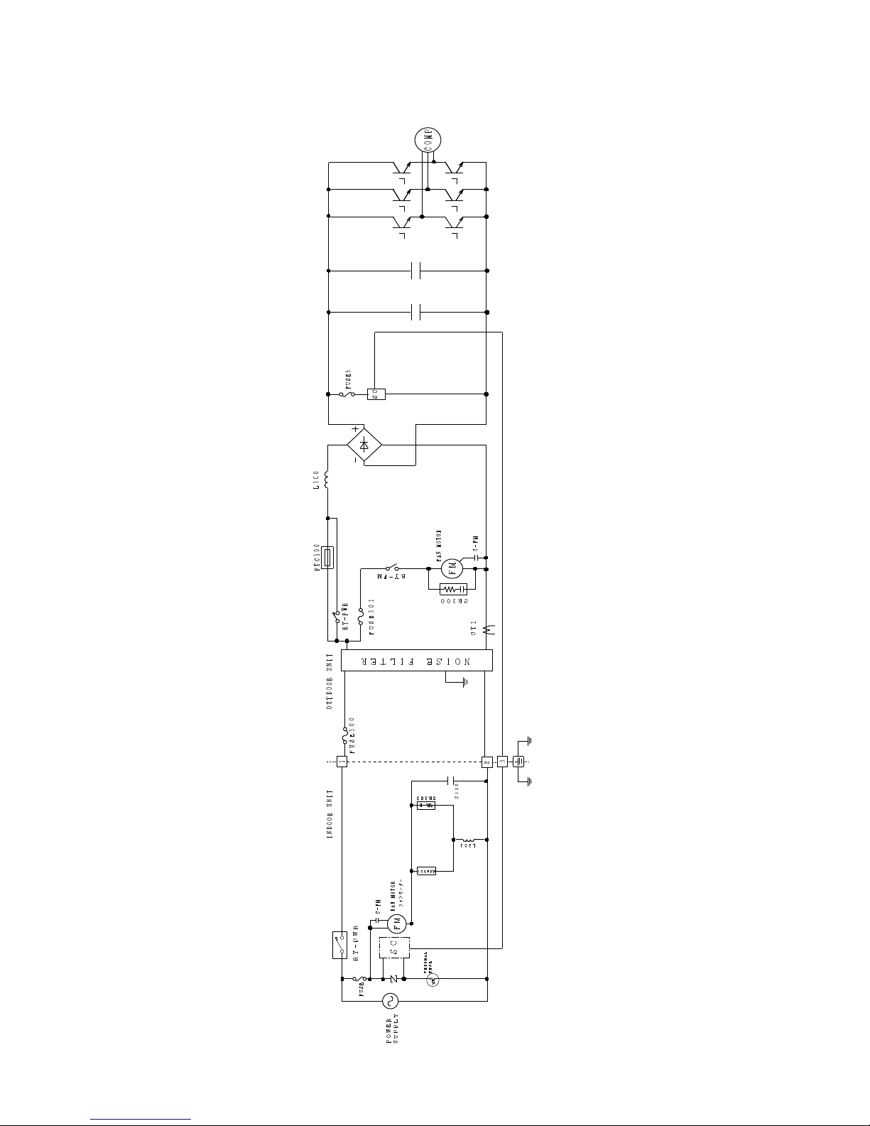
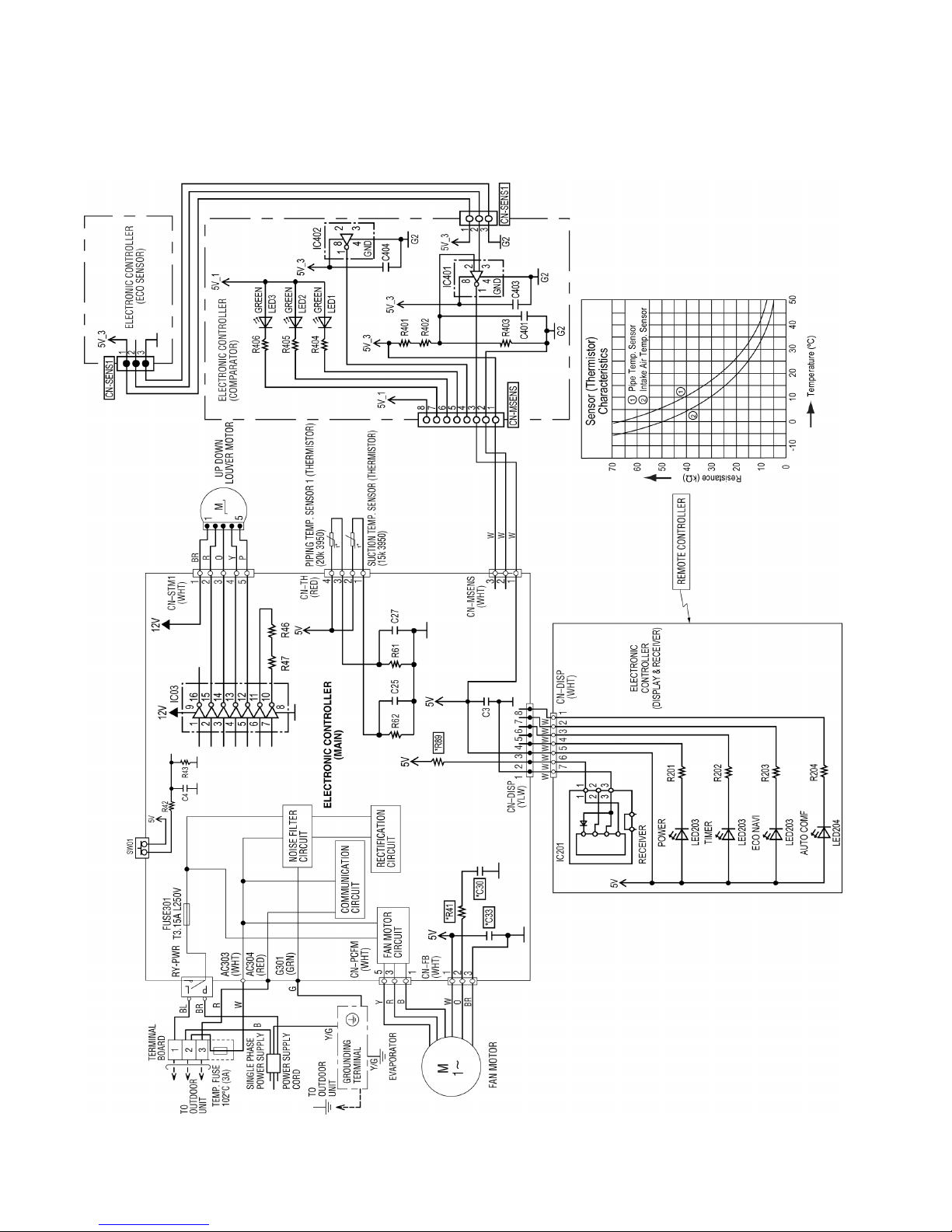
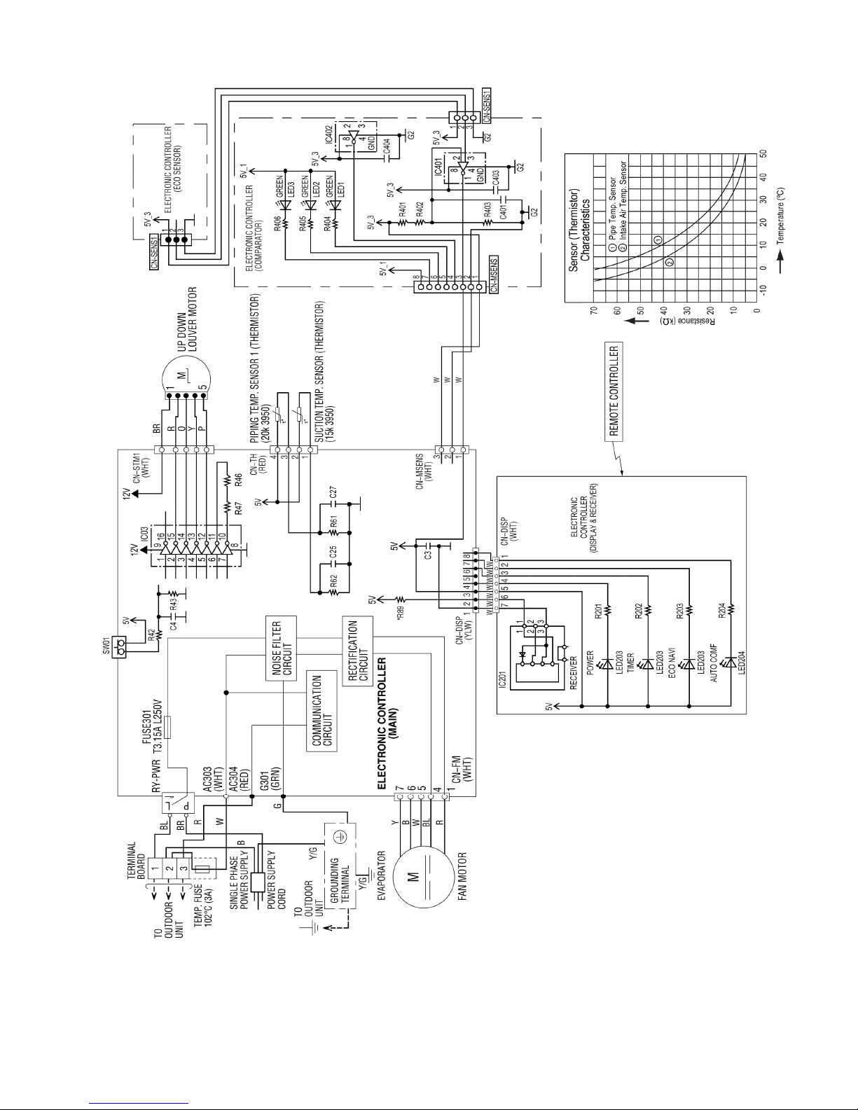
8. Electronic Circuit Diagram
8.1 Indoor Unit
8.1.1 CS-PS9PKV CS-PS12PKV
27
8.1.2 CS-PS18PKV CS-PS24PKV
28
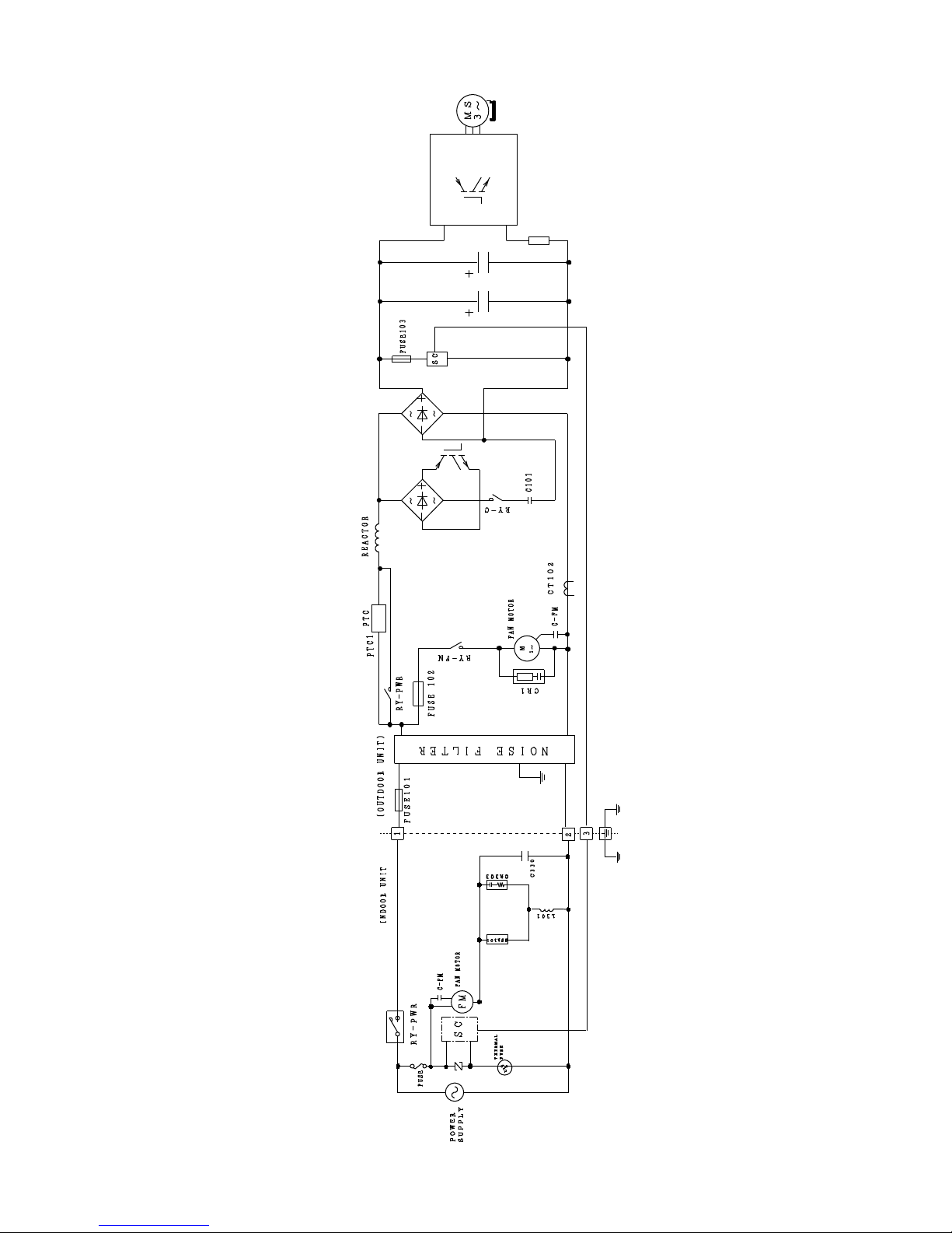
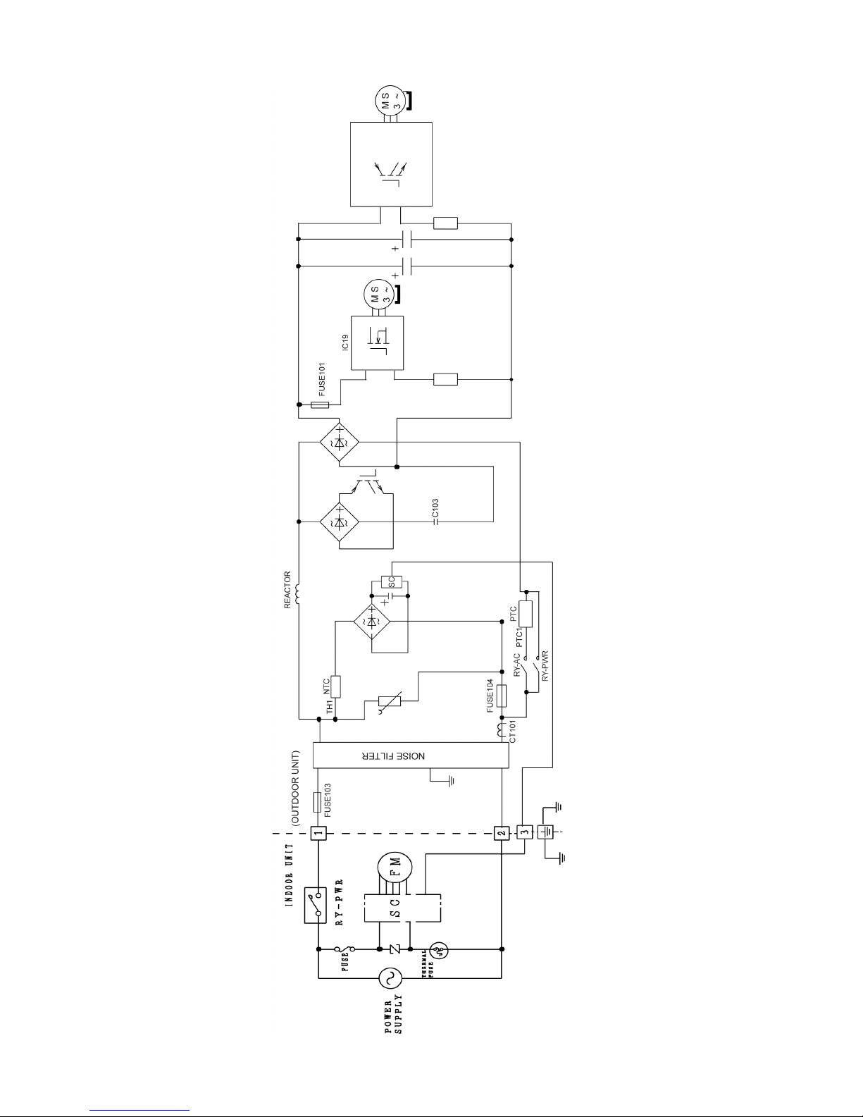
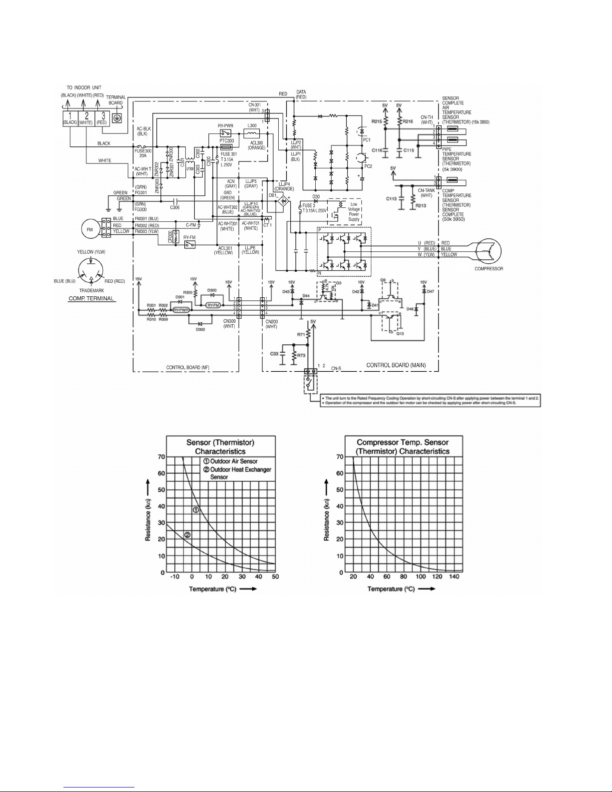
8.2 Outdoor Unit
8.2.1 CU-PS9PKV
29
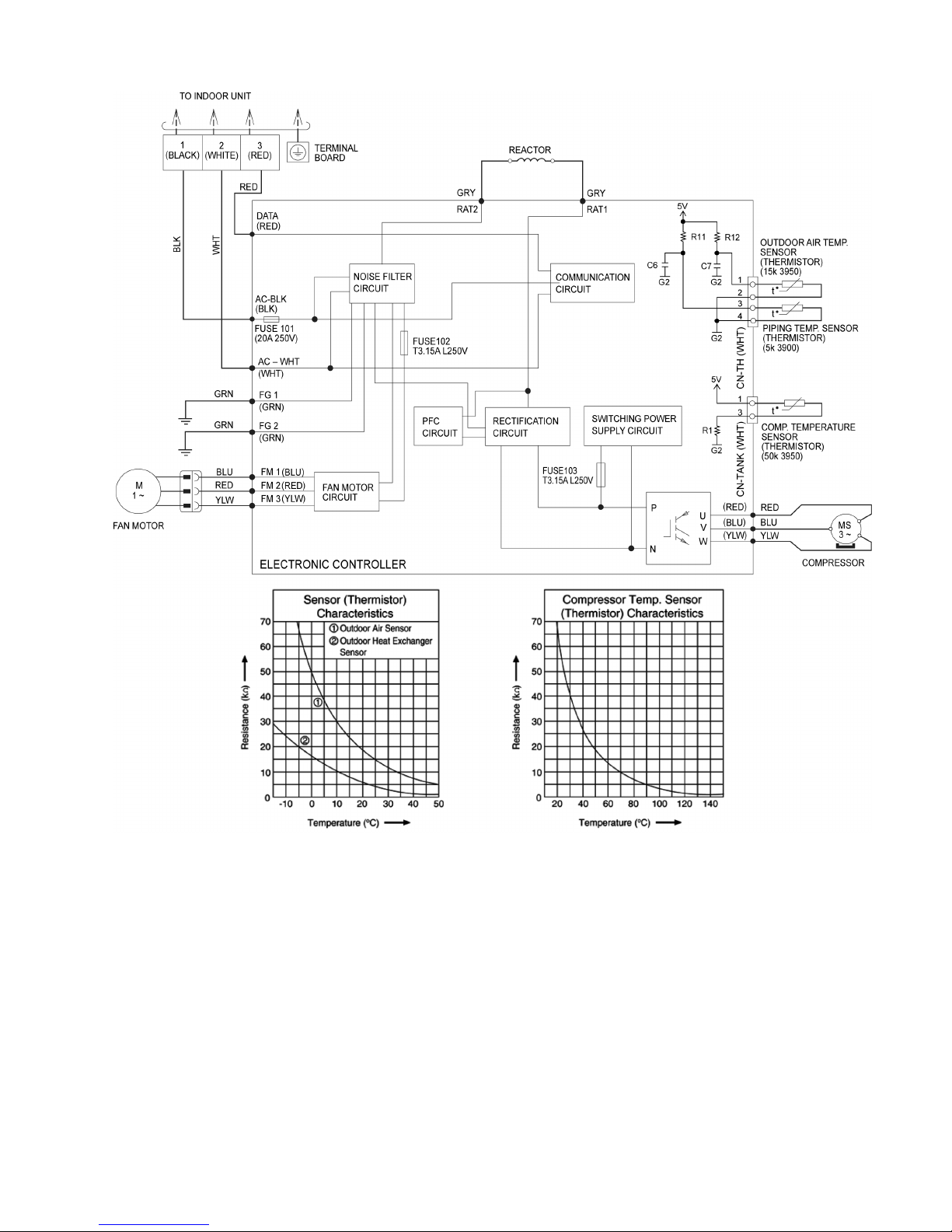
8.2.2 CU-PS12PKV
30
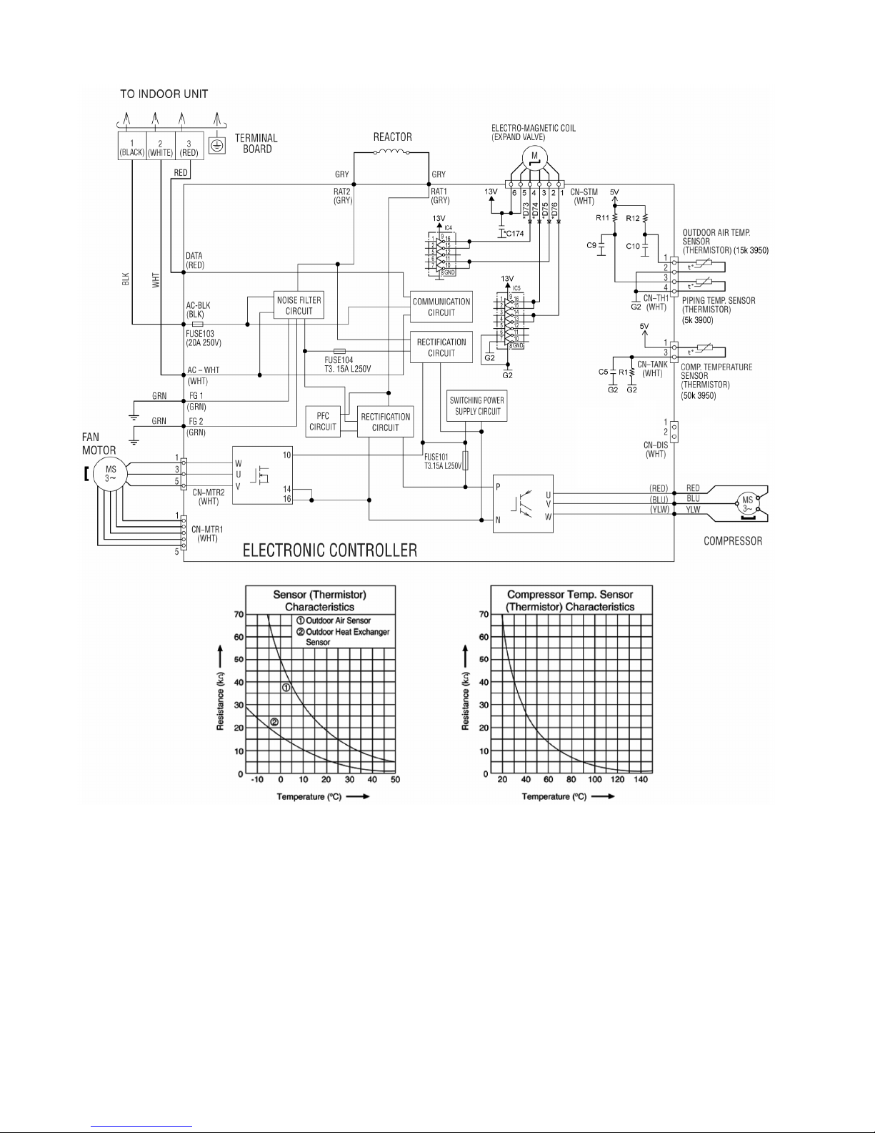
8.2.3 CU-PS18PKV
 Loading...