

Page 1
Order No: PAPAMY1305056CE
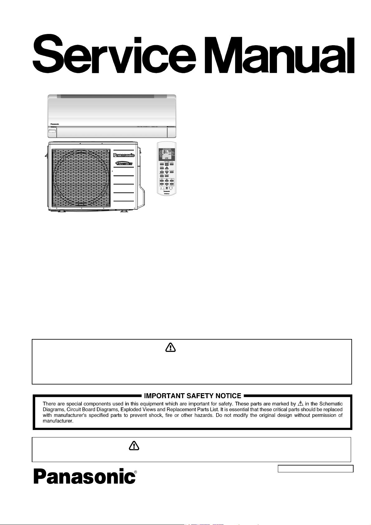
Air Conditioner
Indoor Unit Outdoor Unit
CS-XE9PKUA
CS-XE12PKUA
CU-XE9PKUA
CU-XE12PKUA
Destination
U.S.A.
Canada
This service information is designed for experienced repair technicians only and is not designed for use by the general public.
It does not contain warnings or cautions to advise non-technical individuals of potential dangers in attempting to service a product.
Products powered by electricity should be serviced or repaired only by experienced professional technicians. Any attempt to service
or repair the products dealt with in this service information by anyone else could result in serious injury or death.
WARNING
In order to avoid frostbite, be assured of no refrigerant leakage during the installation or repairing of refrigerant circuit.
PRECAUTION OF LOW TEMPERATURE
© Panasonic Corporation 2013.
Page 2

TABLE OF CONTENTS
1. Safety Precautions ............................................. 3
2. Specifications ..................................................... 5
3. Features ............................................................. 11
4. Location of Controls and Components .......... 12
4.1 Indoor Unit .................................................. 12
4.2 Outdoor Unit ............................................... 12
4.3 Remote Control .......................................... 12
5. Dimensions ....................................................... 13
5.1 Indoor Unit .................................................. 13
5.2 Outdoor Unit ............................................... 14
6. Refrigeration Cycle Diagram ........................... 15
7. Block Diagram .................................................. 16
8. Wiring Connection Diagram ............................ 17
8.1 Indoor Unit .................................................. 17
8.2 Outdoor Unit ............................................... 18
9. Electronic Circuit Diagram .............................. 19
9.1 Indoor Unit .................................................. 19
9.2 Outdoor Unit ............................................... 20
10. Printed Circuit Board ....................................... 21
15. Troubleshooting Guide ....................................50
15.1 Refrigeration Cycle System ........................50
15.2 Breakdown Self Diagnosis Function ...........52
15.3 Error Codes Table ......................................53
15.4 Self-diagnosis Method ................................55
16. Disassembly and Assembly Instructions ......82
16.1 Indoor Electronic Controllers, Cross Flow Fan
and Indoor Fan Motor Removal
Procedures ...................................................82
16.2 Outdoor Electronic Controller Removal
Procedure ....................................................87
17. Technical Data ..................................................88
17.1 Operation Characteristics ...........................88
17.2 Sensible Capacity Chart .............................96
18. Exploded View and Replacement Parts
List .....................................................................97
18.1 Indoor Unit ..................................................97
18.2 Outdoor Unit ............................................ 100
10.1 Indoor Unit .................................................. 21
10.2 Outdoor Unit ............................................... 23
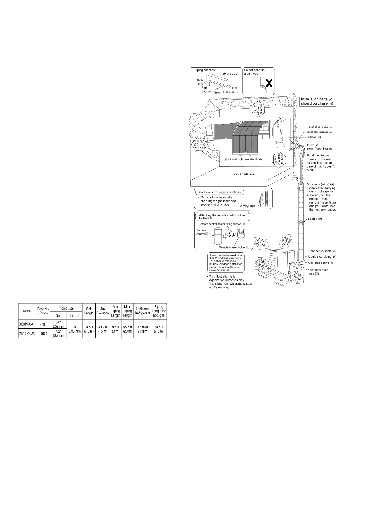
11. Installation Instruction ..................................... 24
11.1 Select the Best Location ............................. 24
11.2 Indoor Unit .................................................. 25
11.3 Outdoor Unit ............................................... 29
12. Operation Control ............................................. 32
12.1 Basic Function ............................................ 32
12.2 Indoor Fan Motor Operation ....................... 33
12.3 Outdoor Fan Motor Operation .................... 34
12.4 Airflow Direction .......................................... 35
12.5 Quiet operation (Cooling Mode/Cooling area
of Dry Mode) ............................................... 36
12.6 Quiet Operation (Heating) .......................... 36
12.7 Powerful Mode Operation ........................... 37
12.8 Timer Control .............................................. 37
12.9 Auto Restart Control ................................... 37
12.10 Indication Panel .......................................... 37
12.11 Room Freeze Protection Function (RFP)
Operation .................................................... 38
12.12 AUTO COMFORT and ECONAVI
Operation .................................................... 38
13. Protection Control ............................................ 44
13.1 Protection Control For All Operations ......... 44
13.2 Protection Control For Cooling & Soft Dry
Operation .................................................... 46
13.3 Protection Control For Heating
Operation .................................................... 47
14. Servicing Mode ................................................. 48
14.1 Auto OFF/ON Button .................................. 48
14.2 Remote Control Button ............................... 49
2
Page 3
1. Safety Precautions
Read the following “SAFETY PRECAUTIONS” carefully before perform any servicing.
Electrical work must be installed or serviced by a licensed electrician. Be sure to use the correct rating of the power plug and
main circuit for the model installed.
The caution items stated here must be followed because these important contents are related to safety. The meaning of each
indication used is as below. Incorrect installation or servicing due to ignoring of the instruction will cause harm or damage,
and the seriousness is classified by the following indications.
This indication shows the possibility of causing death or serious injury.
WARNING
CAUTION
The items to be followed are classified by the symbols:
Carry out test run to confirm that no abnormality occurs after the servicing. Then, explain to user the operation, care and
maintenance as stated in instructions. Please remind the customer to keep the operating instructions for future reference.
This indication shows the possibility of causing injury or damage to properties.
This symbol denotes item that is PROHIBITED from doing.
WARNING
1. Do not modify the machine, part, material during repairing service.
2. If wiring unit is supplied as repairing part, do not repair or connect the wire even only partial wire break. Exchange the whole wiring unit.
3. Do not wrench the fasten terminal. Pull it out or insert it straightly.
Engage dealer or specialist for installation and servicing. If installation of servicing done by the user is defective, it will cause water
4.
leakage, electrical shock or fire.
5. Install according to this installation instructions strictly. If installation is defective, it will cause water leakage, electric shock or fire.
Use the attached accessories parts and specified parts for installation and servicing. Otherwise, it will cause the set to fall, water leakage,
6.
fire or electrical shock.
Install at a strong and firm location which is able to withstand the set’s weight. If the strength is not enough or installation is not properly
7.
done, the set will drop and cause injury.
For electrical work, follow the local national wiring standard, regulation and the installation instruction. An independent circuit and single
8.
outlet must be used. If electrical circuit capacity is not enough or defect found in electrical work, it will cause electrical shock or fire.
This equipment must installed with an Earth Leakage Circuit Breaker (ELCB) or Ground Fault Current Interrupter (GFCI) or Appliance
9.
Leakage Current Interrupter (ALCI) that has been certified by an NRTL Certified Testing Agency and that is suitable for the voltages and
amperages involved. Otherwise, if may cause electrical shock and fire in case of equipment breakdown.
Do not use joint cable for indoor / outdoor connection cable. Use the specified Indoor/Outdoor connection cable, refer to installation
10.
instruction CONNECT THE CABLE TO THE INDOOR UNIT and connect tightly for indoor / outdoor connection. Clamp the cable so that
no external force will be acted on the terminal. If connecting or fixing is not perfect, it will cause heat up or fire at the connection.
Wire routing must be properly arranged so that control board cover is fixed properly. If control board cover is not fixed perfectly, it will
11.
cause heat-up or fire at the connection point of terminal, fire or electrical shock.
When install or relocate air conditioner, do not let any substance other than the specified refrigerant, eg. air etc. mix into refrigeration
12.
cycle (piping). (Mixing of air etc. will cause abnormal high pressure in refrigeration cycle and result in explosion, injury etc.).
Do not install outdoor unit near handrail of veranda. When installing air-conditioner unit at veranda of high rise building, child may climb
13.
up to outdoor unit and cross over the handrail and causing accident.
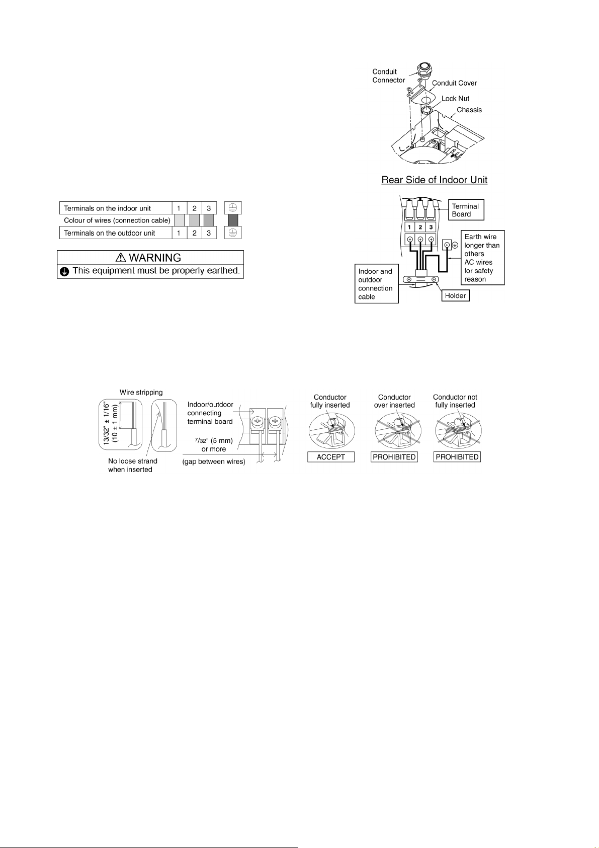
This equipment must be properly earthed. Earth line must not be connected to gas pipe, water pipe, earth of lightning rod and
14.
telephone. Otherwise, it may cause electric shock in case equipment breakdown or insulation breakdown.
15. Keep away from small children, the thin film may cling to nose and mouth and prevent breathing.
Do not use unspecified cord, modified cord, joint cord or extension cord for power supply cord. Do not share the single outlet with
16.
other electrical appliances. Poor contact, poor insulation or over current will cause electrical shock or fire.
Tighten the flare nut with torque wrench according to specified method. If the flare nut is over-tightened, after a long period, the
17.
flare may break and cause refrigerant gas leakage.
For R410A model, use piping, flare nut and tools which is specified for R410A refrigerant. Using of existing (R22) piping, flare nut
and tools may cause abnormally high pressure in the refrigerant cycle (piping), and possibly result in explosion and injury.
18.
Thickness or copper pipes used with R410A must be more than 1/32" (0.8 mm). Never use copper pipes thinner than 1/32"
(0.8 mm). It is desirable that the amount of residual oil is less than 0.0008 oz/ft (40 mg/10 m).
During installation, install the refrigerant piping properly before run the compressor. (Operation of compressor without fixing refrigeration
19.
piping and valves at opened condition will caused suck-in of air, abnormal high pressure in refrigeration cycle and result in explosion,
injury etc).
3
Page 4
WARNING
During pump down operation, stop the compressor before remove the refrigeration piping. (Removal of compressor while compressor is
20.
operating and valves are opened will cause suck-in of air, abnormal high pressure in refrigeration cycle and result in explosion, injury etc.)
After completion of installation or service, confirm there is no leakage or refrigerant gas. It may generate toxic gas when the refrigerant
21.
contacts with fire.
22. Ventilate if there is refrigerant gas leakage during operation. It may cause toxic gas when refrigerant contacts with fire.
23. Do not insert your fingers or other objects into the unit, high speed rotating fan may cause injury.
24. Must not use other parts except original parts described in catalog and manual.
25. Using of refrigerant other than the specified type may cause product damage, burst and injury etc.
CAUTION
Do not install the unit at place where leakage of flammable gas may occur. In case gas leaks and accumulates at surrounding of
1.
the unit, it may cause fire.
Carry out drainage piping as mentioned in installation instructions. If drainage is not perfect, water may enter the room and damage the
2.
furniture.
Tighten the flare nut with torque wrench according to specified method. If the flare nut is over-tightened, after a long period, the flare may
3.
break and cause refrigerant gas leakage.
4. Do not touch outdoor unit air inlet and aluminium fin. It may cause injury.
5. Select an installation location which is easy for maintenance.
Pb free solder has a higher melting point than standard solder; typically the melting point is 50°F – 70°F (30°C – 40°C) higher.
6.
Please use a high temperature solder iron. In case of the soldering iron with temperature control, please set it to 700 ± 20°F (370 ± 10°C).
Pb free solder will tend to splash when heated too high (about 1100°F / 600°C).
Power supply connection to the room air conditioner.
Power supply cord shall be UL listed or CSA approved 3 conductor with minimum AWG14 wires.
Power supply point should be in an easily accessible place for power disconnection in case of emergency.
7.
In some countries, permanent connection of this air conditioner to the power supply is prohibited.
Fix power supply connection to a circuit breaker for permanent connection.
Use NRTL approved fuse or circuit breaker (rating refers to name plate) for permanent connection.
Do not release refrigerant during piping work for installation, servicing, reinstallation and during repairing a refrigerant parts.
8.
Take care of the liquid refrigerant, it may cause frostbite.
9. Installation or servicing work: It may need two people to carry out the installation or servicing work.
10. Do not install this appliance in a laundry room or other location where water may drip from the ceiling, etc.
11. Do not sit or step on the unit, you may fall down accidentally.
Do not touch the sharp aluminium fins or edges of metal parts.
12.
If you are required to handle sharp parts during installation or servicing, please wear hand glove.
Sharp parts may cause injury.
4
Page 5
2. Specifications
Model
Performance Test Condition ARI
Power Supply
Min. Mid. Max. Min. Mid. Max.
Capacity
Running Current A – 2.80 – – 2.50 –
Input Power W 150 540 850 150 540 850
Annual Consumption kWh – – – – – –
Cooling
Indoor Noise (H / L / QLo)
Outdoor Noise (H / L / QLo)
Heating
Indoor Noise (H / L / QLo)
Outdoor Noise (H / L / QLo)
17°F: Rated Capacity (BTU/h) / I. Power (W) 8000 / 750
Compressor
EER
Power Factor % – 93 – – 94 –
Capacity
Running Current A – 4.50 – – 4.00 –
Input Power W 150 860 1.65k 150 860 1.65k
COP
Power Factor % – 92 – – 93 –
5°F: Max. Capacity (BTU/h) 11000
Max Current (A) / Max Input Power (W) 7.8 / 1.71k
Starting Current (A) 4.50
Type Hermetic Motor (Rotary)
Motor Type Brushless (4 poles)
Output Power W 700
Indoor CS-XE9PKUA
Outdoor CU-XE9PKUA
Phase, Hz Single, 60
V 208 230
kW 0.83 2.55 3.51 0.83 2.55 3.51
BTU/h 2800 8700 12000 2800 8700 12000
kcal/h – – – – – –
W/W 5.53 4.72 4.13 5.53 4.72 4.13
BTU/hW 18.65 16.10 14.10 18.65 16.10 14.10
kcal/hW – – – – – –
dB-A 42 / 25 / 20 42 / 25 / 20
Power Level dB 58 / – / – 58 / – / –
dB-A 48 / – / – 48 / – / –
Power Level dB 63 / – / – 63 / – / –
kW 0.89 3.51 5.29 0.89 3.51 5.29
BTU/h 3000 12000 18000 3000 12000 18000
kcal/h – – – – – –
W/W 5.93 4.08 3.21 5.93 4.08 3.21
BTU/hW 20.00 13.95 10.90 20.00 13.95 10.90
kcal/hW – – – – – –
dB-A 42 / 29 / 26 42 / 29 / 26
Power Level dB 58 / – / – 58 / – / –
dB-A 48 / – / – 48 / – / –
Power Level dB 63 / – / – 63 / – / –
5
Page 6
Model
Indoor CS-XE9PKUA
Outdoor CU-XE9PKUA
Type Cross-Flow Fan
Material ASG33
Motor Type DC / Transistor (8-poles)
Input Power W 47.0
Output Power W 40
QLo
Indoor Fan
Speed
SHi
Cool rpm 570
Heat rpm 740
Cool rpm 660
Lo
Heat rpm 810
Cool rpm 850
Me
Heat rpm 1000
Cool rpm 1040
Hi
Heat rpm 1190
Cool rpm 1140
Heat rpm 1290
Type Propeller Fan
Material PP
Motor Type DC (8-poles)
Input Power W –
Outdoor Fan
Output Power W 40
Speed Hi
Cool rpm 600
Heat rpm 670
Min Circuit Ampacity 15.0
Max. Overcurrent Protection 15.0
SEER / HSPF 28.50 / 12.50
Moisture Removal L/h (Pt/h) 0.5 (1.3)
3
/min (ft3/min) 5.0 (170)
3
/min (ft3/min) 6.3 (220)
3
/min (ft3/min) 8.9 (310)
3
/min (ft3/min) 11.5 (405)
3
/min (ft3/min) 12.8 (450)
3
/min (ft3/min) 34.6 (1220) 34.6 (1220)
Indoor
Airflow
Outdoor
Airflow
QLo
Lo
Me
Hi
SHi
Hi
Cool m
Heat m3/min (ft3/min) 7.4 (260)
Cool m
Heat m3/min (ft3/min) 8.3 (290)
Cool m
Heat m3/min (ft3/min) 10.9 (380)
Cool m
Heat m3/min (ft3/min) 13.5 (475)
Cool m
Heat m3/min (ft3/min) 14.9 (520)
Cool m
Heat m3/min (ft3/min) 39.1 (1380) 39.1 (1380)
Control Device Expansion Valve
Refrigeration
Cycle
Refrigerant Oil cm3 FV50S (320)
Refrigerant Type g (oz) R410A, 1.15k (40.6)
Height(I/D / O/D) mm (inch) 295 (11-5/8) / 695 (27-3/8)
Dimension
Width (I/D / O/D) mm (inch) 870 (34-9/32) / 875 (34-15/32)
Depth (I/D / O/D) mm (inch) 255 (10-1/16) / 320 (12-5/8)
Weight Net (I/D / O/D) kg (lb) 11 (24) / 44 (97)
6
Page 7
Model
Pipe Diameter (Liquid / Gas) mm (inch) 6.35 (1/4) / 9.52 (3/8)
Standard length m (ft) 7.5 (24.6)
Length range (min – max) m (ft) 3 (9.8) ~ 20 (65.6)
I/D & O/D Height different m (ft) 15.0 (49.2)
Piping
Additional Gas Amount g/m (oz/ft) 20 (0.2)
Length for Additional Gas m (ft) 7.5 (24.6)
Drain Hose
Indoor Heat
Exchanger
Outdoor
Heat
Exchanger
Air Filter
Power Supply Cord A Nil
Indoor
Operation
Range
Outdoor
Operation
Range
1. Cooling capacities are based on indoor temperature of 80°F (26.7°C) DRY BULB, 67°F (19.4°C) WET BULB and outdoor air temperature of
95°F (35°C) DRY BULB, 75°F (23.8°C) WET BULB.
2. Heating capacities are based on indoor temperature of 70°F (21.1°C) DRY BULB, 60°F (15.6°C) WET BULB and outdoor air temperature of
47°F (8.3°C) DRY BULB, 43°F (6.1°C) WET BULB.
3. 17°F (-8.3°C) Heating Capacity and Input Power measured at 230V, indoor temperature 70°F (21.1°C), outdoor 17/15°F (-8.3/-9.4°C).
4. 5°F (-15°C) Heating Capacity measured at 230V, indoor temperature 70°F (21.1°C), outdoor 5°F (-15°C/-).
5. Specifications are subjected to change without prior notice for further improvement.
Inner Diameter mm (inch) 16.7 (5/8)
Length mm(inch) 650 (25-5/8)
Fin Material Aluminium (Pre Coat)
Fin Type Slit Fin
Row × Stage × FPI 2 × 17 × 21
Size (W × H × L) mm (inch) 636.5 × 357 × 25.4 (25-1/16 × 14-1/16 × 1)
Fin Material Aluminium / Blue Coated
Fin Type Corrugated Fin
Row × Stage × FPI 2 × 31 × 18
Size (W × H × L) mm (inch) 36.4 × 651 × 854.5:824.5 (1-7/16 × 25-11/16 × 33-11/16:32-15/32)
Material Polypropelene
Type One-touch
Power Supply Outdoor
Thermostat Electronic Control
Protection Device Electronic Control
Dry Bulb Wet Bulb
Cooling
Heating
Cooling
Heating
Indoor CS-XE9PKUA
Outdoor CU-XE9PKUA
Maximum °F/°C 89.6/32 73.4/23
Minimum °F/°C 60.8/16 51.8/11
Maximum °F/°C 86.0/30 –/–
Minimum °F/°C 60.8/16 –/–
Maximum °F/°C 114.8/46 78.8/26
Minimum °F/°C 0.0/-18 –/–
Maximum °F/°C 75.2/24 64.4/18
Minimum °F/°C 0.0/-18 -2.2/-19
7
Page 8
Model
Performance Test Condition ARI
Power Supply
Min. Mid. Max. Min. Mid. Max.
Capacity
Running Current A – 4.20 – – 3.80 –
Input Power W 150 800 1.05k 150 800 1.05k
Annual Consumption kWh – – – – – –
Cooling
Indoor Noise (H / L / QLo)
Outdoor Noise (H / L / QLo)
Heating
Indoor Noise (H / L / QLo)
Outdoor Noise (H / L / QLo)
17°F: Rated Capacity (BTU/h) / I. Power (W) 10400 / 1.05k
Compressor
EER
Power Factor % – 92 – – 92 –
Capacity
Running Current A – 5.80 – – 5.20 –
Input Power W 150 1.15k 2.10k 150 1.15k 2.10k
COP
Power Factor % – 95 – – 96 –
5°F: Max. Capacity (BTU/h) 12500
Max Current (A) / Max Input Power (W) 9.5 / 2.15k
Starting Current (A) 5.80
Type Hermetic Motor (Rotary)
Motor Type Brushless (4 poles)
Output Power W 700
Indoor CS-XE12PKUA
Outdoor CU-XE12PKUA
Phase, Hz Single, 60
V 208 230
kW 0.83 3.36 4.10 0.83 3.36 4.10
BTU/h 2800 11500 14000 2800 11500 14000
kcal/h – – – – – –
W/W 5.53 4.20 3.90 5.53 4.20 3.90
BTU/hW 18.65 14.35 13.30 18.65 14.35 13.30
kcal/hW – – – – – –
dB-A 45 / 28 / 20 45 / 28 / 20
Power Level dB 61 / – / – 61 / – / –
dB-A 49 / – / – 49 / – / –
Power Level dB 64 / – / – 64 / – / –
kW 0.89 4.05 6.72 0.89 4.05 6.72
BTU/h 3000 13800 23000 3000 13800 23000
kcal/h – – – – – –
W/W 5.93 3.52 3.20 5.93 3.52 3.20
BTU/hW 20.00 12.00 10.95 20.00 12.00 10.95
kcal/hW – – – – – –
dB-A 44 / 35 / 32 44 / 35 / 32
Power Level dB 60 / – / – 60 / – / –
dB-A 49 / – / – 49 / – / –
Power Level dB 64 / – / – 64 / – / –
8
Page 9
Model
Indoor CS-XE12PKUA
Outdoor CU-XE12PKUA
Type Cross-Flow Fan
Material ASG33
Motor Type DC / Transistor (8-poles)
Input Power W 47.0
Output Power W 40
Cool rpm 570
Heat rpm 890
Cool rpm 710
Lo
Heat rpm 970
Cool rpm 1010
Heat rpm 1110
Cool rpm 1300
Hi
Heat rpm 1250
Cool rpm 1350
Heat rpm 1350
Indoor Fan
Speed
QLo
Me
SHi
Type Propeller Fan
Material PP
Motor Type DC (8-poles)
Input Power W –
Outdoor Fan
Output Power W 40
Speed Hi
Cool rpm 600
Heat rpm 750
Min Circuit Ampacity 15.0
Max. Overcurrent Protection 20.0
SEER / HSPF 25.50 / 12.00
Moisture Removal L/h (Pt/h) 1.1 (2.3)
3
/min (ft3/min) 5.0 (170)
3
/min (ft3/min) 6.9 (240)
3
/min (ft3/min) 11.1 (390)
3
/min (ft3/min) 15.0 (530)
3
/min (ft3/min) 15.7 (550)
3
/min (ft3/min) 35.9 (1265) 35.9 (1265)
Indoor
Airflow
Outdoor
Airflow
QLo
Lo
Me
Hi
SHi
Hi
Cool m
Heat m3/min (ft3/min) 9.4 (330)
Cool m
Heat m3/min (ft3/min) 10.5 (370)
Cool m
Heat m3/min (ft3/min) 12.4 (430)
Cool m
Heat m3/min (ft3/min) 14.3 (505)
Cool m
Heat m3/min (ft3/min) 15.7 (550)
Cool m
Heat m3/min (ft3/min) 44.0 (1555) 44.0 (1555)
Control Device Expansion Valve
Refrigeration
Cycle
Refrigerant Oil cm3 FV50S (320)
Refrigerant Type g (oz) R410A, 1.15k (40.6)
Height(I/D / O/D) mm (inch) 295 (11-5/8) / 695 (27-3/8)
Dimension
Width (I/D / O/D) mm (inch) 870 (34-9/32) / 875 (34-15/32)
Depth (I/D / O/D) mm (inch) 255 (10-1/16) / 320 (12-5/8)
Weight Net (I/D / O/D) kg (lb) 11 (24) / 44 (97)
9
Page 10
Model
Pipe Diameter (Liquid / Gas) mm (inch) 6.35 (1/4) / 12.70 (1/2)
Standard length m (ft) 7.5 (24.6)
Length range (min – max) m (ft) 3 (9.8) ~ 20 (65.6)
I/D & O/D Height different m (ft) 15.0 (49.2)
Piping
Additional Gas Amount g/m (oz/ft) 20 (0.2)
Length for Additional Gas m (ft) 7.5 (24.6)
Drain Hose
Indoor Heat
Exchanger
Outdoor
Heat
Exchanger
Air Filter
Power Supply Cord A Nil
Indoor
Operation
Range
Outdoor
Operation
Range
1. Cooling capacities are based on indoor temperature of 80°F (26.7°C) DRY BULB, 67°F (19.4°C) WET BULB and outdoor air temperature of
95°F (35°C) DRY BULB, 75°F (23.8°C) WET BULB.
2. Heating capacities are based on indoor temperature of 70°F (21.1°C) DRY BULB, 60°F (15.6°C) WET BULB and outdoor air temperature of
47°F (8.3°C) DRY BULB, 43°F (6.1°C) WET BULB.
3. 17°F (-8.3°C) Heating Capacity and Input Power measured at 230V, indoor temperature 70°F (21.1°C), outdoor 17/15°F (-8.3/-9.4°C).
4. 5°F (-15°C) Heating Capacity measured at 230V, indoor temperature 70°F (21.1°C), outdoor 5°F (-15°C/-).
5. Specifications are subjected to change without prior notice for further improvement.
Inner Diameter mm (inch) 16.7 (5/8)
Length mm (inch) 650 (25-5/8)
Fin Material Aluminium (Pre Coat)
Fin Type Slit Fin
Row × Stage × FPI 2 × 17 × 21
Size (W × H × L) mm (inch) 636.5 × 357 × 25.4 (25-11/16 × 14-1/16 × 1)
Fin Material Aluminium / Blue Coated
Fin Type Corrugated Fin
Row × Stage × FPI 2 × 31 × 18
Size (W × H × L) mm (inch) 36.4 × 651 × 854.5:824.5 (1-7/16 × 25-11/16 × 33-11/16:32-15/32)
Material Polypropelene
Type One-touch
Power Supply Outdoor
Thermostat Electronic Control
Protection Device Electronic Control
Dry Bulb Wet Bulb
Cooling
Heating
Cooling
Heating
Indoor CS-XE12PKUA
Outdoor CU-XE12PKUA
Maximum °F/°C 89.6/32 73.4/23
Minimum °F/°C 60.8/16 51.8/11
Maximum °F/°C 86.0/30 –/–
Minimum °F/°C 60.8/16 –/–
Maximum °F/°C 114.8/46 78.8/26
Minimum °F/°C 0.0/-18 –/–
Maximum °F/°C 75.2/24 64.4/18
Minimum °F/°C 0.0/-18 -2.2/-19
10
Page 11

3. Features
Inverter Technology
o Wider output power range
o Energy saving
o Quick Cooling
o Quick Heating
o More precise temperature control
Environment Protection
o Non-ozone depletion substances refrigerant (R410A)
Long Installation Piping
o Long piping up to 65.6ft (20 meters) during single split connection only
Easy to use remote control
Quality Improvement
o Random auto restart after power failure for safety restart operation
o Gas leakage protection
o Prevent compressor reverse cycle
o Inner protector to protect compressor
o Noise prevention during soft dry operation
Operation Improvement
o Quiet mode to reduce the indoor unit operating sound
o Powerful mode to reach the desired room temperature quickly
o 24-hour timer setting
o RFP (Room Freeze Protection) operation is designed to circulate the air in High mode for monitoring the
temperature. Used in spaces that are unoccupied during the winter, for the purpose of protecting any
equipment or appliances which may be destroyed as a result of freezing temperature.
Serviceability Improvement
o Breakdown Self Diagnosis function
`
11
Page 12
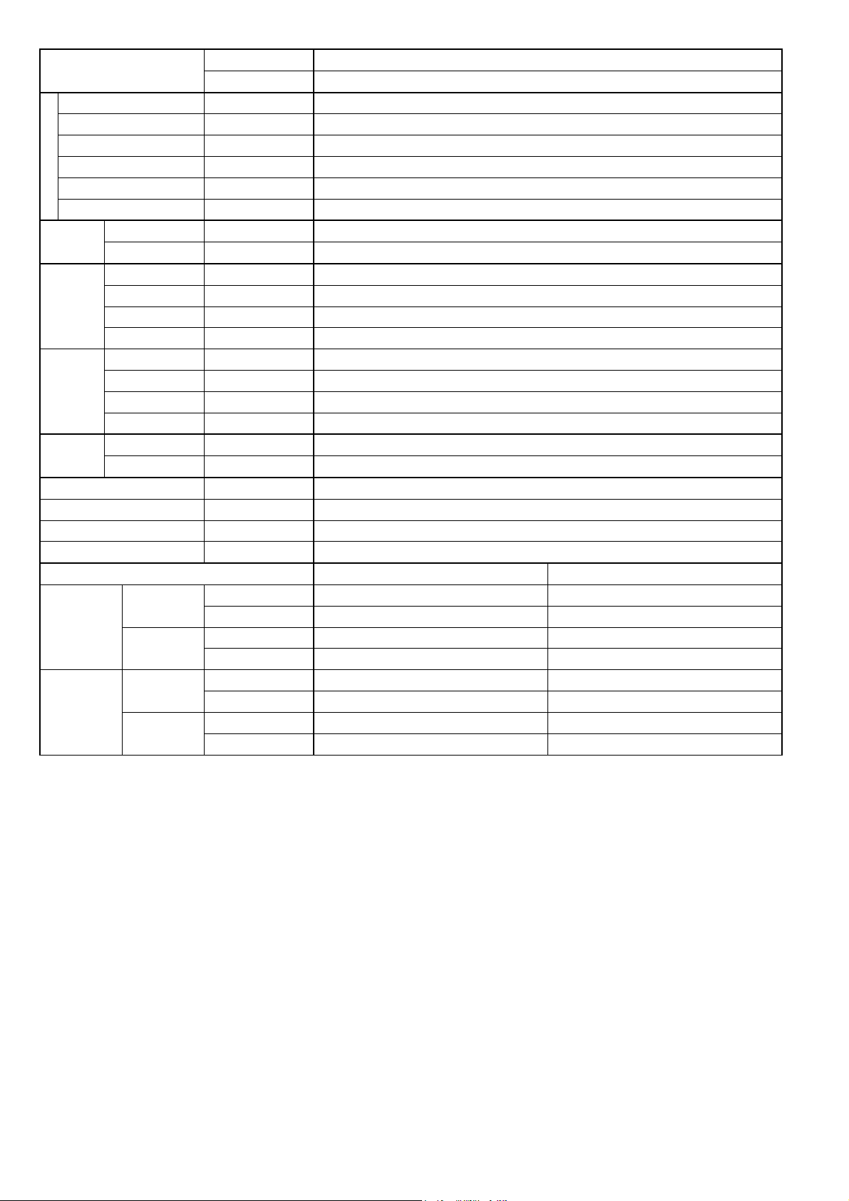
4. Location of Controls and Components
4.1 Indoor Unit
4.2 Outdoor Unit
4.3 Remote Control
12
Page 13
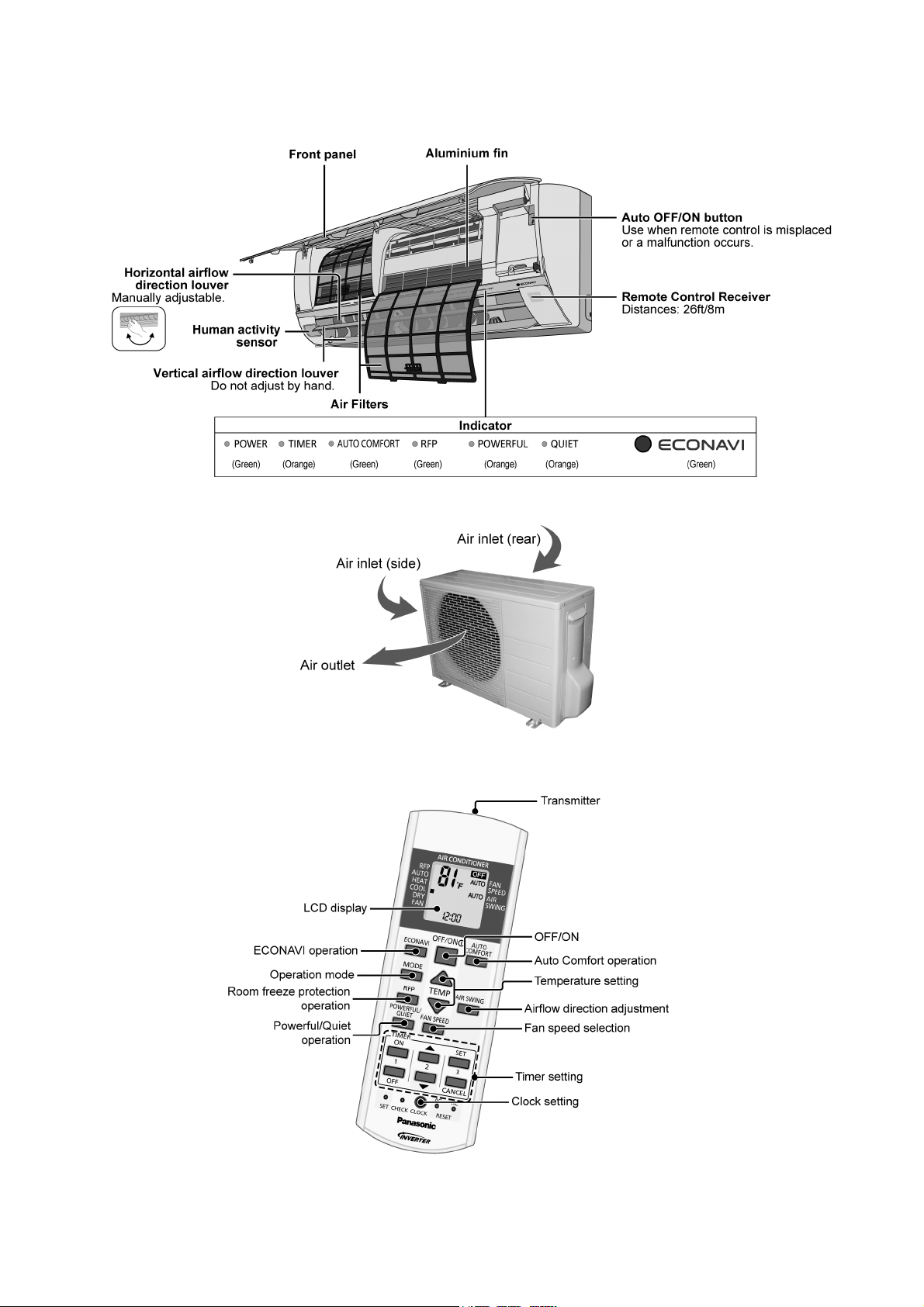
5. Dimensions
5.1 Indoor Unit
13
Page 14
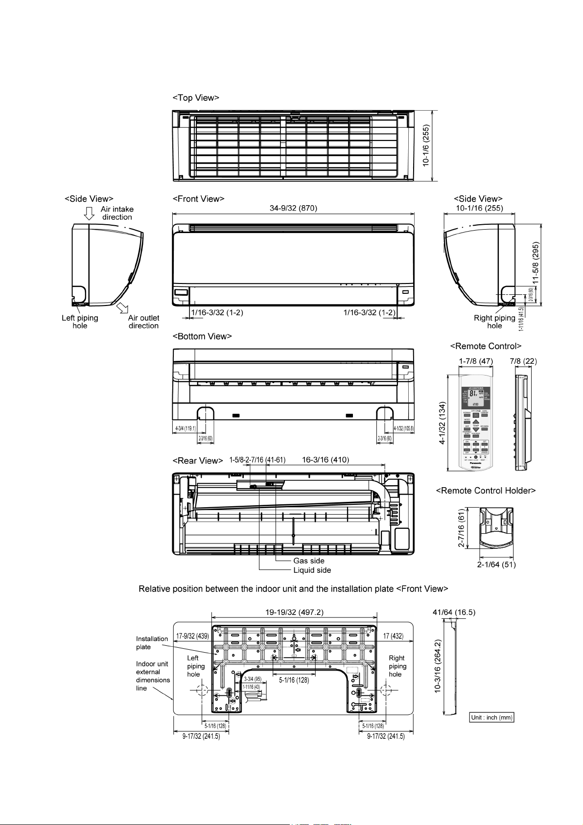
5.2 Outdoor Unit
14
Page 15
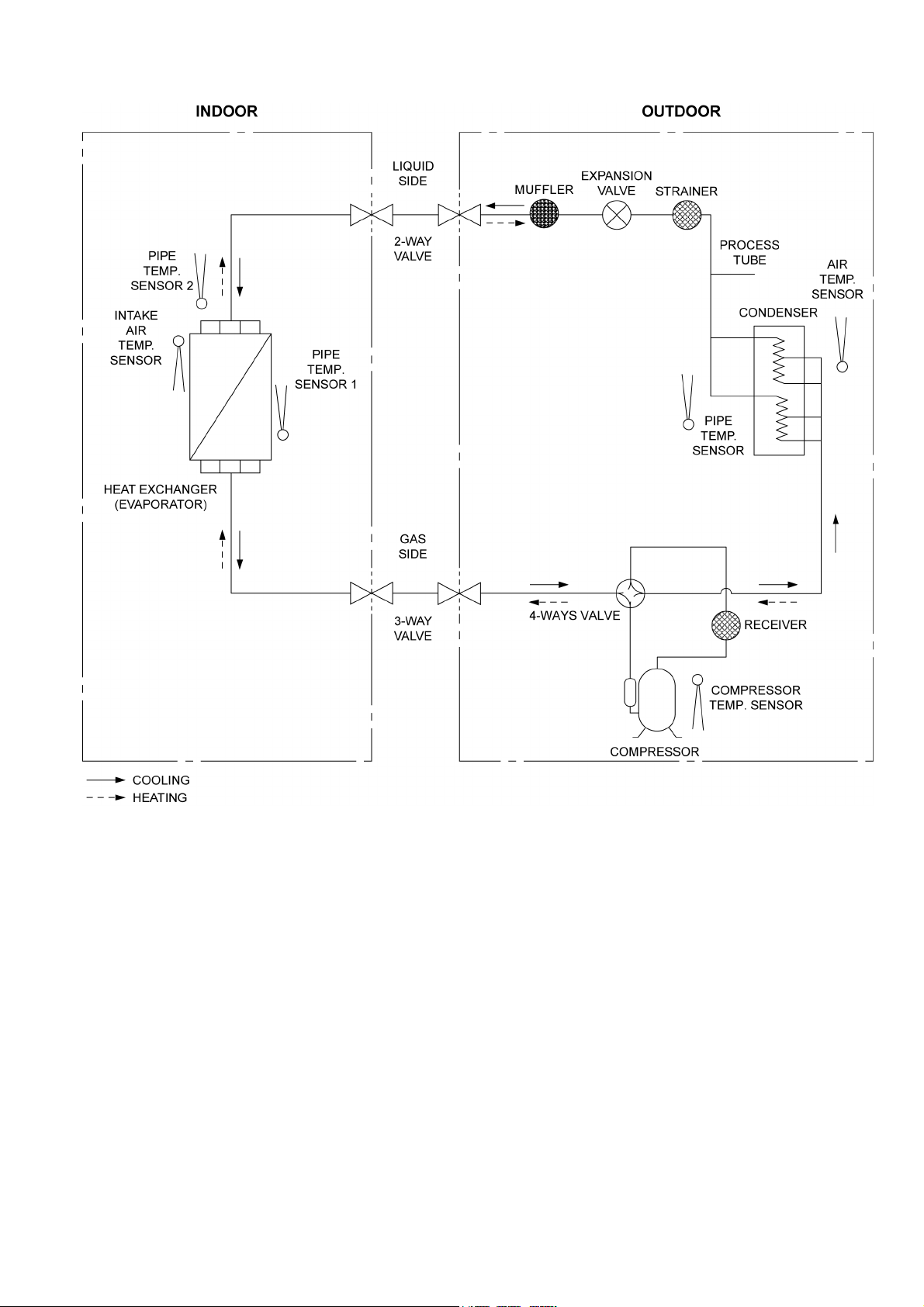
6. Refrigeration Cycle Diagram
15
Page 16
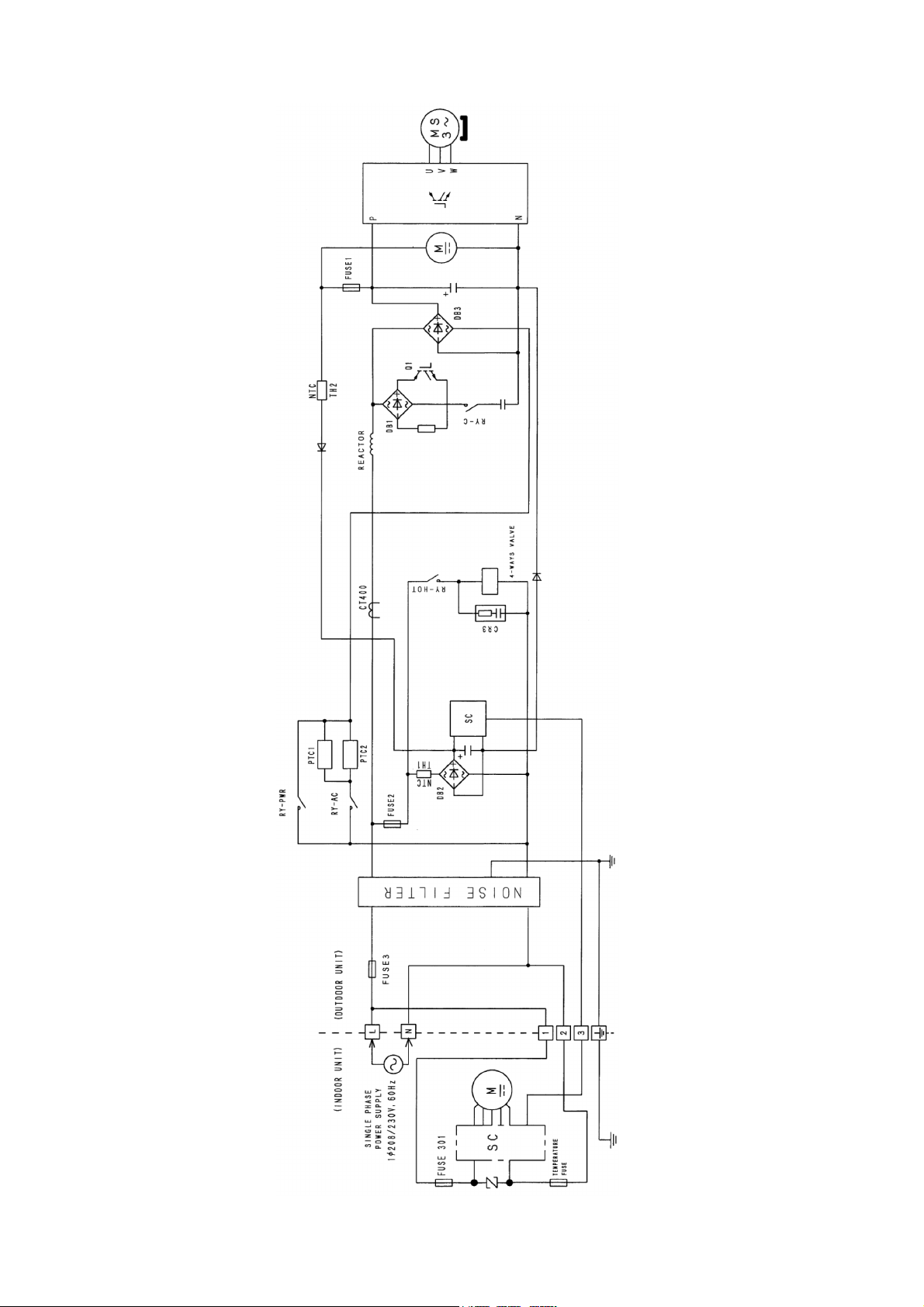
7. Block Diagram
16
Page 17
8. Wiring Connection Diagram
8.1 Indoor Unit
17
Page 18

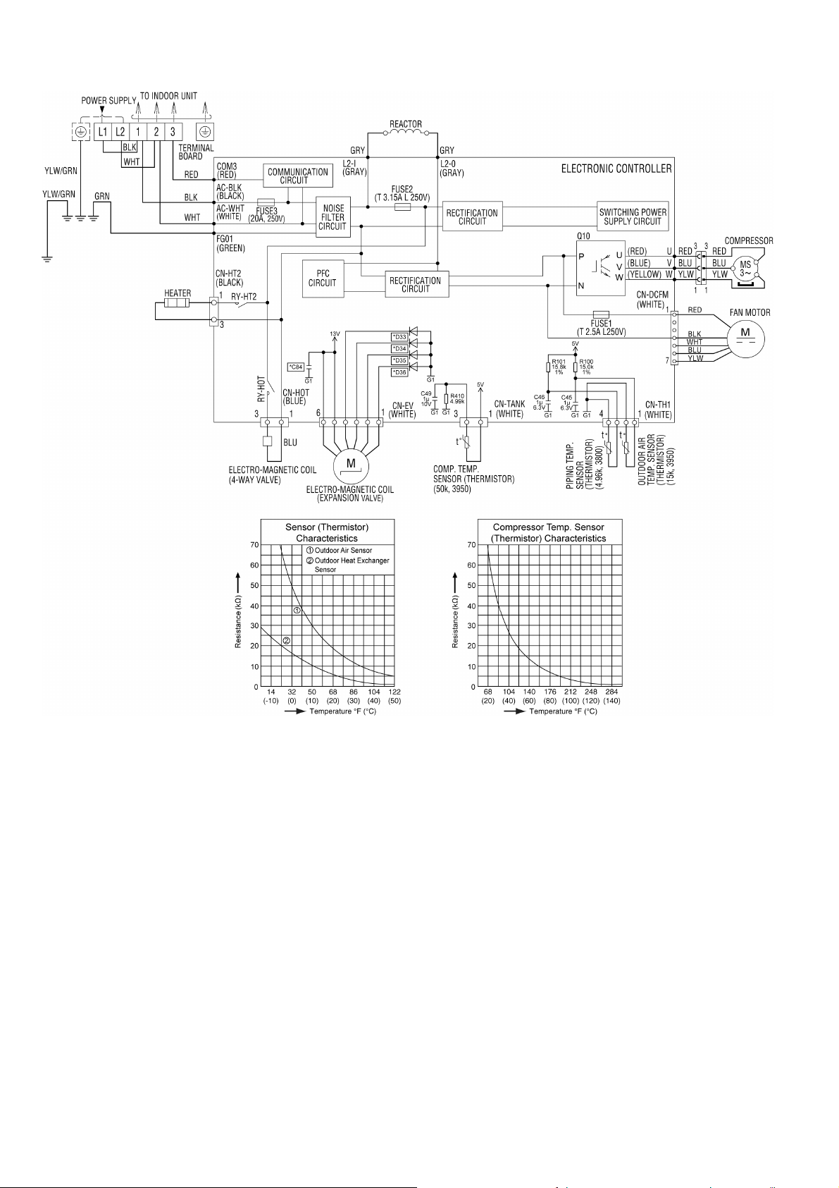
8.2 Outdoor Unit
Resistance of Compressor Windings
MODEL CU-XE9/12PK
CONNECTION 5RS102XHB21 (Ω)
U-V 1.741
U-W 1.765
V-W 1.711
Note: Resistance at 20°C of ambient temperature.
18
Page 19
9. Electronic Circuit Diagram
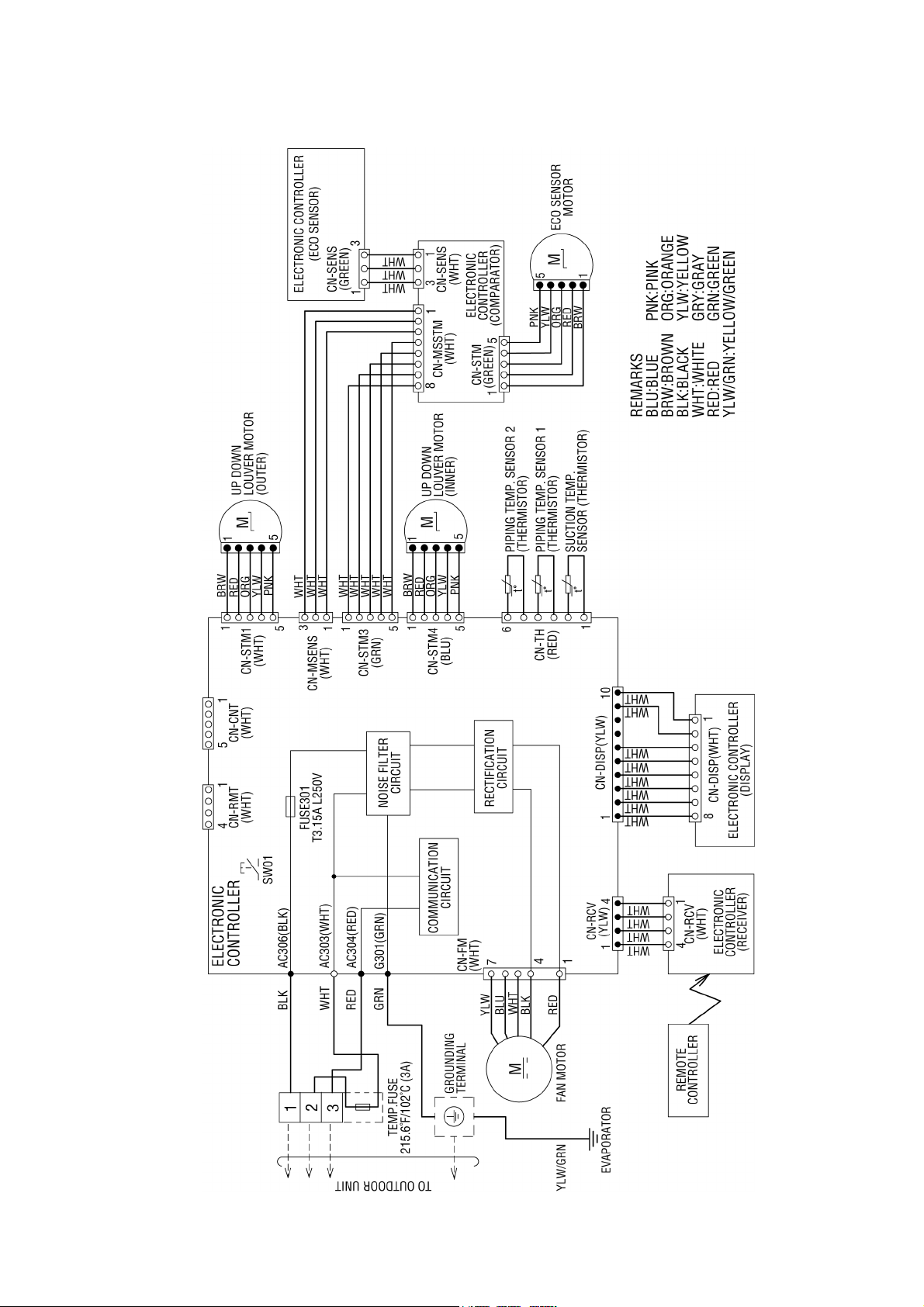
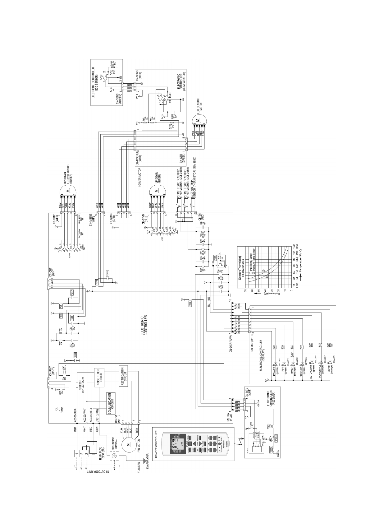
9.1 Indoor Unit
19
Page 20
9.2 Outdoor Unit
20
Page 21
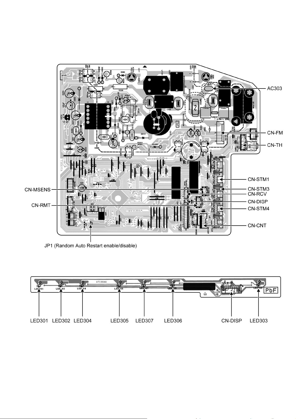
10. Printed Circuit Board
10.1 Indoor Unit
10.1.1 Main Printed Circuit Board
10.1.2 Indicator Printed Circuit Board
21
Page 22
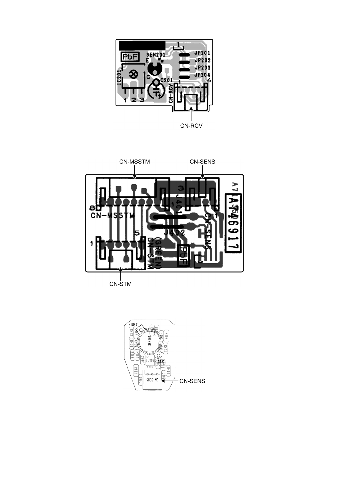
10.1.3 Receiver Printed Circuit Board
10.1.4 Comparator Printed Circuit Board
10.1.5 Human Activity Sensor Printed Circuit Board
22
Page 23
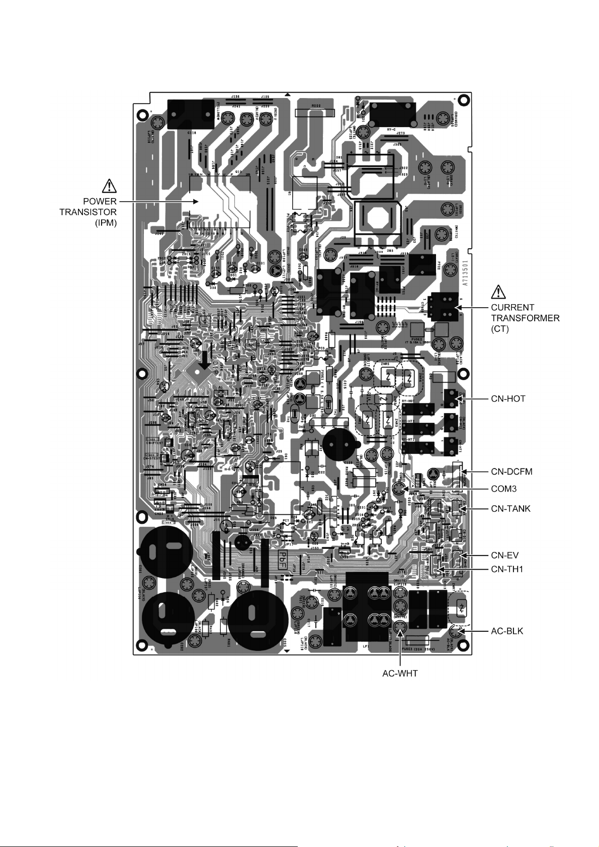
10.2 Outdoor Unit
10.2.1 Main Printed Circuit Board
23
Page 24
11. Installation Instruction
11.1 Select the Best Location
11.1.1 Indoor Unit
Do not install the unit in excessive oil fume area
such as kitchen, workshop and etc.
There should not be any heat source or steam
near the unit.
There should not be any obstacles blocking the air
circulation.
A place where air circulation in the room is good.
A place where drainage can be easily done.
A place where noise prevention is taken into
consideration.
Do not install the unit near the door way.
Ensure the spaces indicated by arrows from the
wall, ceiling, fence or other obstacles.
Mount with the lowest moving parts at least 8ft
(2.4 m) above floor or grade level.
11.1.2 Outdoor Unit
If an awning is built over the unit to prevent direct
sunlight or rain, be careful that heat radiation from
the condenser is not obstructed.
There should not be any animal or plant which
could be affected by hot air discharged.
Keep the spaces indicated by arrows from wall,
ceiling, fence or other obstacles.
Do not place any obstacles which may cause a
short circuit of the discharged air.
If piping length is over the [piping length for
additional gas], additional refrigerant should be
added as shown in the table.
Recommended installation height for outdoor unit
should be above the seasonal snow level.
Example: For XE9PKUA
If the unit is installed at 32.8 ft (10 m) distance, the
quantity of additional refrigerant should be 1.64 oz (50
g) .... (32.8 - 24.6) ft x 0.2 oz/ft = 1.64 oz. ((10-7.5) m
x 20 g/m = 50 g)
11.1.3 Indoor/Outdoor Unit Installation
Diagram
24
Page 25
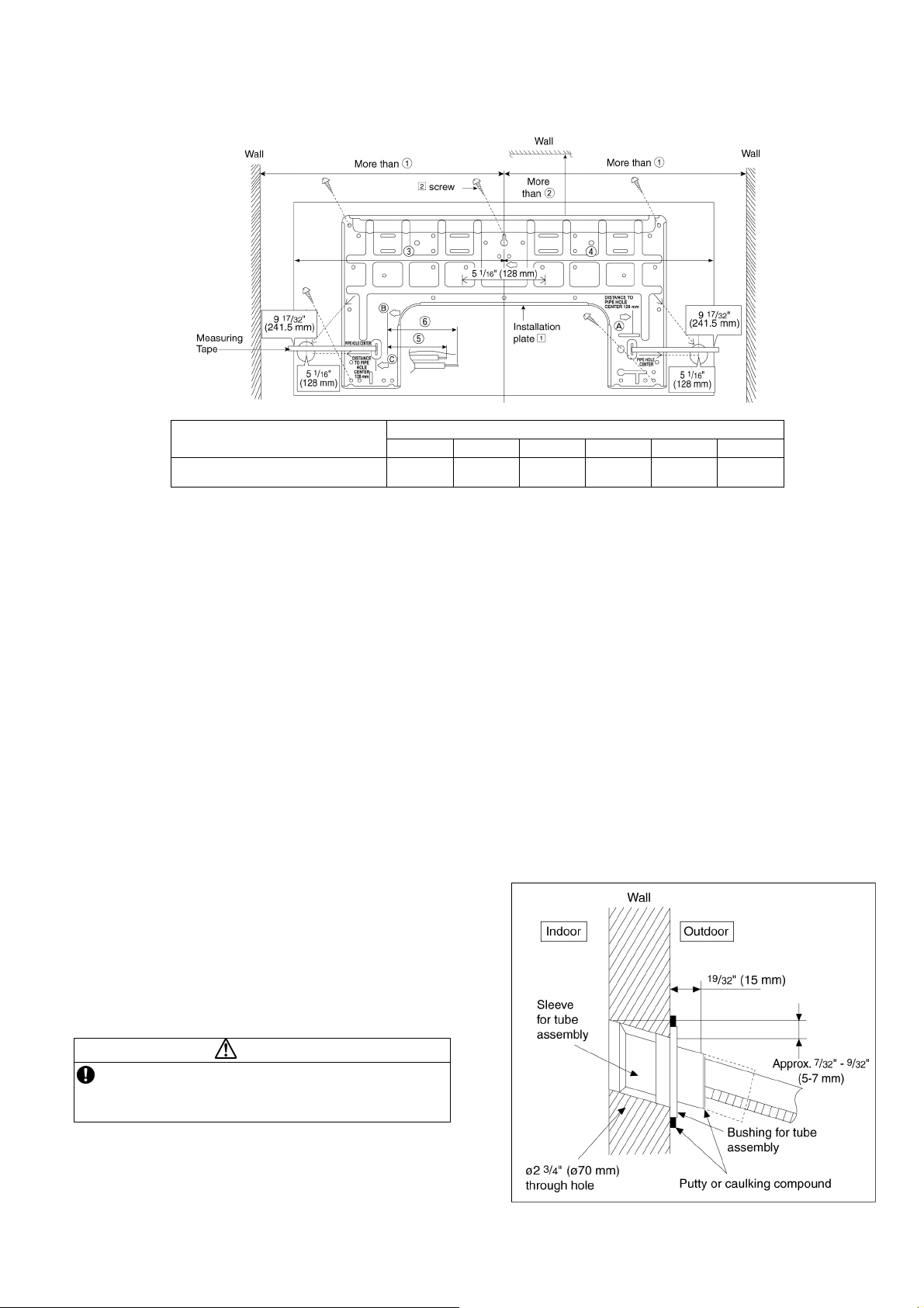
11.2 Indoor Unit
The mounting wall shall be strong and solid enough to prevent it from vibration.
Model
XE9PKUA, XE12PKUA
c d e f g h
19-9/32"
(490 mm)
3-7/32"
(82 mm)
Dimension
17-9/32"
(439 mm)
17"
(432 mm)
1-11/16"
(43 mm)
The center of installation plate should be at more than
The distance from installation plate edge to ceiling should more than
From installation plate left edge to unit’s left side is
From installation plate right edge to unit’s right is
B : For left side piping, piping connection for liquid should be about ○5 from this line.
○
: For left side piping, piping connection for gas should be about
1 at right and left of the wall.
○
2.
○
3.
○
4.
○
6 from this line.
○
1 Mount the installation plate on the wall with 5 screws or more (at least 5 screws).
(If mounting the unit on the concrete wall, consider using anchor bolts.)
o Always mount the installation plate horizontally by aligning the marking-off line with the thread and using
a level gauge.
2 Drill the piping plate hole with ø2-3/4" (ø70 mm) hole-core drill.
o Line according to the left and right side of the installation plate. The meeting point of the extended line is
the center of the hole. Another method is by putting measuring tape at position as shown in the diagram
above. The hole center is obtained by measuring the distance namely 5-1/16" (128 mm) for left and right
hole respectively.
o Drill the piping hole at either the right or the left and the hole should be slightly slanting to the outdoor
side.
3-3/4"
(95 mm)
11.2.1 To Drill a Hole in the Wall and
Install a Sleeve of Piping
1 Insert the piping sleeve to the hole.
2 Fix the bushing to the sleeve.
3 Cut the sleeve until it extrudes about 19/32"
(15 mm) from the wall.
CAUTION
When the wall is hollow, please be sure to use the
sleeve for tube assembly to prevent dangers
caused by mice biting the connection cable.
4 Finish by sealing the sleeve with putty or
caulking compound at the final stage.
25
Page 26
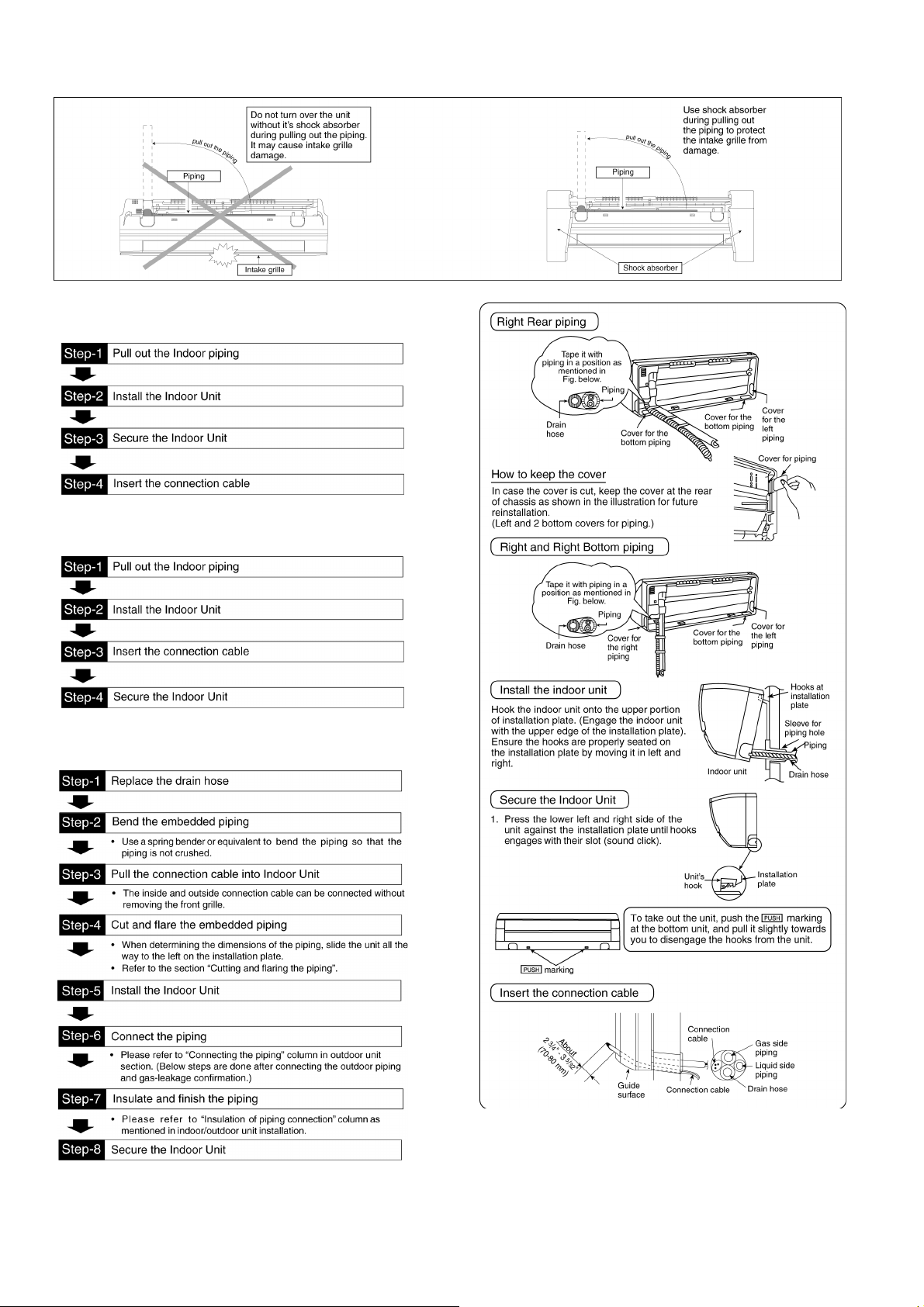
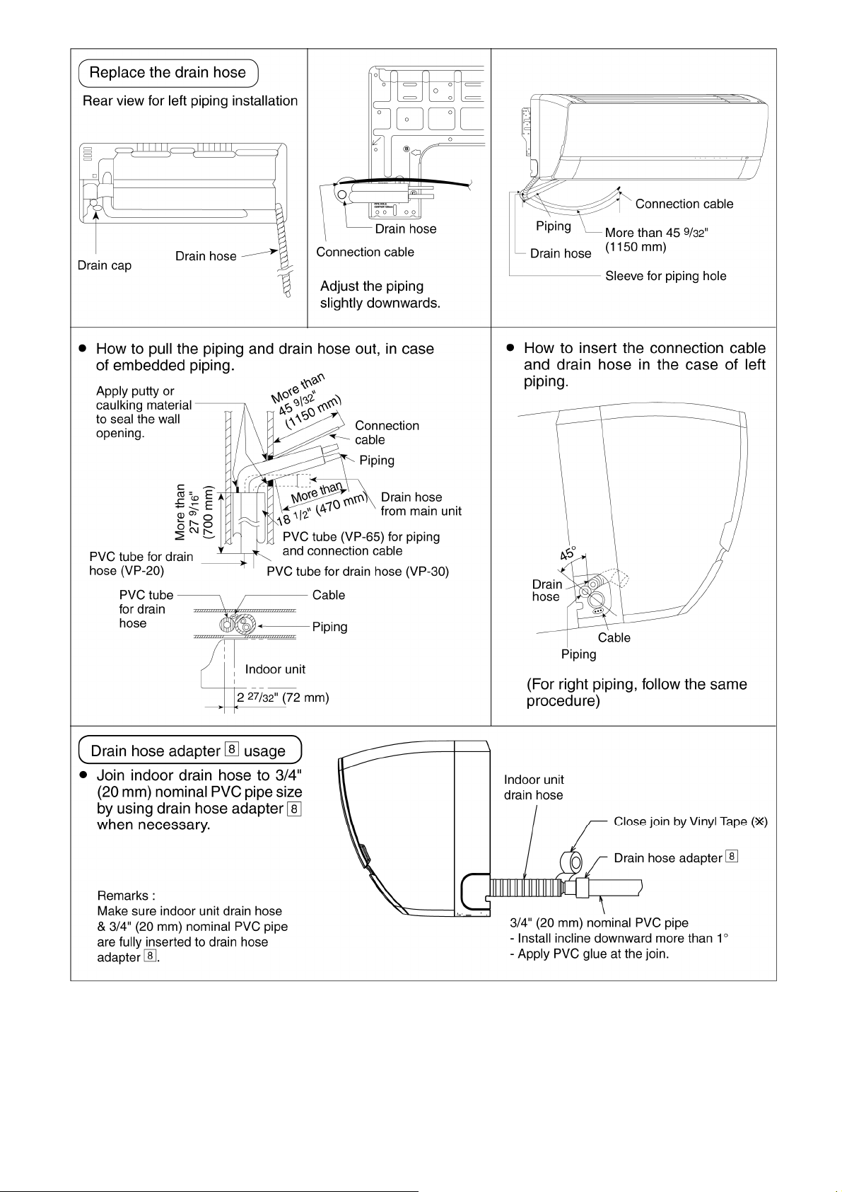
11.2.2 Indoor Unit Installation
11.2.2.1 For the right rear piping
11.2.2.2 For the right bottom piping
11.2.2.3 For the embedded piping
(This can be used for left rear piping and bottom
piping also.)
26
Page 27
27
Page 28
11.2.3 Connect the Cable to the Indoor Unit
1 The inside and outside connection cable can
be connected without removing the front grille.
2 Unscrew the conduit cover and fix the conduit
connector to conduit cover with lock nut, then
secure it against chassis.
3 Connection cable between indoor unit and
outdoor unit should be UL listed or CSA
approved 4 conductor wires minimum AWG16
in accordance with local electric codes.
o Ensure the colour of wires of outdoor unit
and terminal number are the same as the
indoor's respectively.
o Earth lead wire shall be Yellow/Green
(Y/G) in colour and shall be longer than
other lead wires as shown in the figure
for electrical safety in case of slipping.
11.2.3.1 Wire Stripping and Connecting Requirement
28
Page 29
11.3 Outdoor Unit
11.3.1 Install the Outdoor Unit
After selecting the best location, start installation according to Indoor/Outdoor Unit Installation Diagram.
1 Fix the unit on concrete or rigid frame firmly and horizontally with a bolt nut ø13/32" (ø10 mm).
2 When installing at roof, please consider strong wind and earthquake.
Please fasten the installation stand firmly with bolt or nails.
AB
C
D
11.3.2 Connect the Piping
11.3.2.1 Connecting the Piping to
Indoor
Please make flare after inserting flare nut (locate at
joint portion, of tube assembly) onto the copper pipe.
(In case of using long piping)
Connect the piping
Align the center of piping and sufficiently tighten
the flare nut with fingers.
Further tighten the flare nut with torque wrench in
specified torque as stated in the table.
Model A B C D
XE9PKUA,
XE12PKUA
24-1/8"
(613 mm)
5-5/32"
(131 mm)
5/8"
(16 mm)
Do not over tighten, over tightening may cause gas leakage
Piping size Torque
1/4" (6.35 mm) 13.3 Ibf.ft [18N•m (1.8 kgf.m)]
3/8" (9.52 mm) 31.0 Ibf.ft [42 N•m (4.3 kgf.m)]
1/2" (12.7 mm) 40.6 Ibf.ft [55 N•m (5.6 kgf.m)]
5/8" (15.88 mm) 47.9 Ibf.ft [65 N•m (6.6 kgf.m)]
3/4" (19.05 mm) 73.8 Ibf.ft [100 N•m (10.2 kgf.m)]
14-3/16"
(360.5 mm)
11.3.2.2 Connecting the Piping to
Outdoor
Decide piping length and then cut by using pipe cutter.
Remove burrs from cut edge.
Make flare after inserting the flare nut (located at valve)
onto the copper pipe.
Align center of piping to valve and then tighten with
torque wrench to the specified torque as stated in the
table.
Spanner
or Wrench
11.3.2.3 Gas leak checking
Pressure test to system to 400 PSIG with dry nitrogen, in stages. Thoroughly leak check the system.
If the pressure holds, release the nitrogen and proceed to section 11.3.3.
To r qu e
wrench
29
Page 30
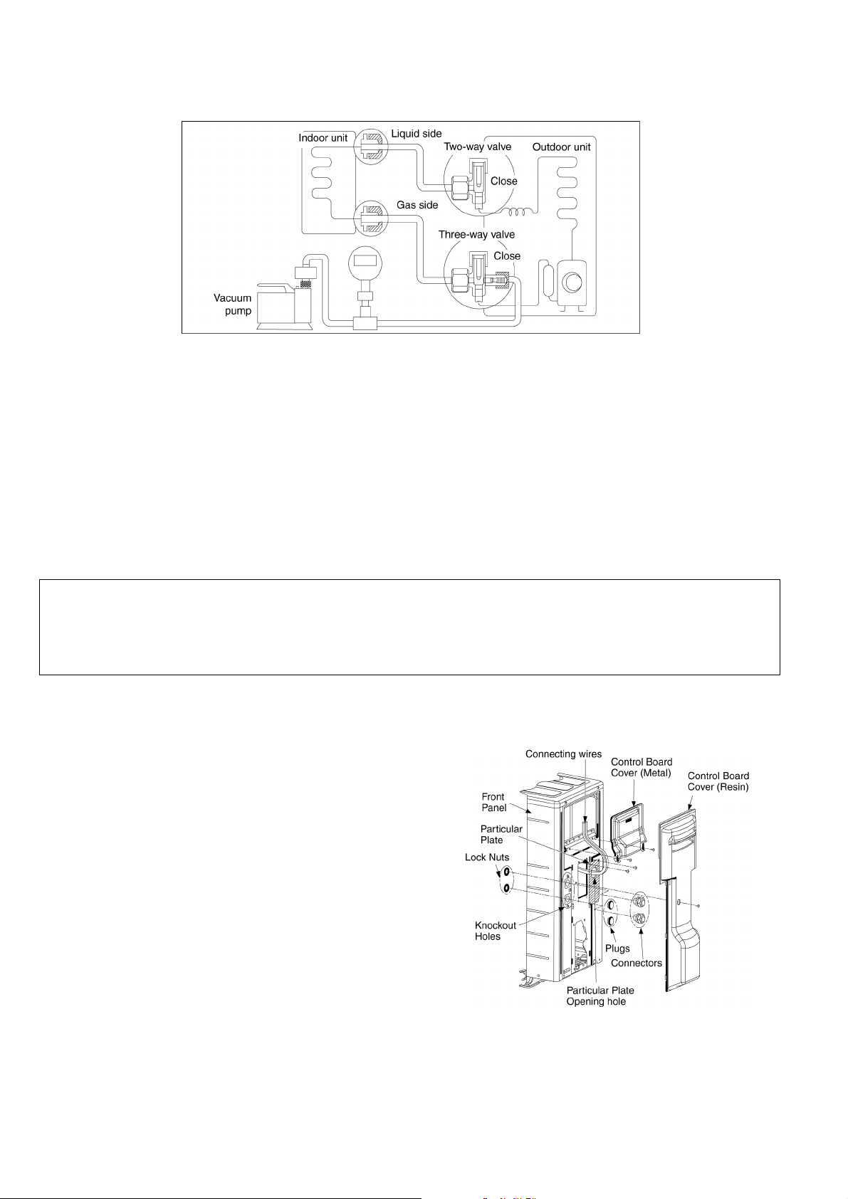
11.3.3 Evacuation of the Equipment
WHEN INSTALLING AN AIR CONDITIONER, BE SURE TO EVACUATE THE AIR INSIDE THE INDOOR UNIT AND
PIPES in the following procedure.
1 Connect a charging hose with a push pin to the Low side of a charging set and the service port of the 3-way
valve.
2 Connect the micron gauge between vacuum pump and service port of outdoor units.
3 Turn on the power switch of the vacuum pump and make sure that connect digital micron gauge and to pull
down to a value of 500 microns.
4 To make sure micron gauge a value 500 microns and close the low side valve of the charging set and turn off
the vacuum pump.
5 Disconnect the vacuum pump house from the service port of the 3-way valve.
6 Tighten the service port caps of the 3-way valve at a torque of 13.3 Ibf.ft (18 N•m) with a torque wrench.
7 Remove the valve caps of both of the 2-way valve and 3-way valve. Position both of the valves to “Open”
using a hexagonal wrench (5/32" (4 mm)).
8 Mount valve caps onto the 2-way valve and the 3-way valve.
o Be sure to check for gas leakage.
If micron gauge value does not descend 500 microns, take the following measures:
- If the leak stops when the piping connections are tightened further, continue working from step e.
- If the leak does not stop when the connections are retightened, repair location of leak.
- Do not release refrigerant during piping work for installation and reinstallation.
- Be careful with the liquid refrigerant, it may cause frostbite.
11.3.4 Connect the Cable to the Outdoor Unit
1 Remove control board cover (Resin and
Metal).
2 Remove particular plate.
3 Remove plugs.
4 Fix the conduit connectors to the knockout
holes with lock-nuts, then secure them against
the side panel.
5 All wires pass through conduits & particular
plate’s opening hole.
6 Connecting wire between indoor unit and
outdoor unit should be UL listed or CSA
approved 4 conductor wires minimum AWG16
in accordance with local electric codes.
7 Wire connection to the power supply
(208/230V 60Hz) through circuit breaker.
o Connect the UL listed or CSA approved
wires minimum AWG14 to the terminal
board, and connect the other end of the
wires to ELCB/ GFCI.
8 Connect the power supply cord and
connecting wire between indoor unit and
outdoor unit according to the diagram below.
30
Page 31

9 Secure the wire onto the control board with
the holder (clamper).
10 After completing wiring connections, reattach
the particular plate and control board cover
(metal and resin) to the original position with
the screws.
11 For wire stripping and connection
requirement, refer to instruction 11.2.3 of
indoor unit.
WARNING
This equipment must be properly earthed.
Earth lead wire shall be Yellow/Green (Y/G) in
colour and should be longer than other lead wires
as shown in the figure for electrical safety in case
of slipping.
11.3.5 Piping Insulation
1 Please carry out insulation at pipe connection portion as mentioned in Indoor/Outdoor Unit Installation
Diagram. Please wrap the insulated piping end to prevent water from going inside the piping.
2 If drain hose or connecting piping is in the room (where dew may form), please increase the insulation by
using POLY-E FOAM with thickness 1/4" (6 mm) or above.
11.3.5.1 Cutting and flaring the piping
1 Please cut using pipe cutter and then remove the burrs.
2 Remove the burrs by using reamer. If burrs are not removed, gas leakage may be caused. Turn the piping
end down to avoid the metal powder entering the pipe.
3 Please make flare after inserting the flare nut onto the copper pipes.
31
Page 32

12. Operation Control
12.1 Basic Function
Inverter control, which equipped with a microcomputer in determining the most suitable operating mode as time
passes, automatically adjusts output power for maximum comfort always. In order to achieve the suitable operating
mode, the microcomputer maintains the set temperature by measuring the temperature of the environment and
performing temperature shifting. The compressor at outdoor unit is operating following the frequency instructed by
the microcomputer at indoor unit that judging the condition according to internal setting temperature and intake air
temperature.
12.1.1 Internal Setting Temperature
Once the operation starts, remote control setting temperature will be taken as base value for temperature shifting
processes. These shifting processes are depending on the air conditioner settings and the operation environment.
The final shifted value will be used as internal setting temperature and it is updated continuously whenever the
electrical power is supplied to the unit.
12.1.2 Cooling Operation
12.1.2.1 Thermostat control
Compressor is OFF when Intake Air Temperature - Internal Setting Temperature < -2.7°F (-1.5°C) continue for
3 minutes.
When compressor is OFF (Thermostat OFF) and AUTO FAN is set, the fan will stop periodically.
Compressor is ON after waiting for 3 minutes, if the Intake Air Temperature - Internal Setting Temperature >
Compressor OFF point.
12.1.3 Soft Dry Operation
12.1.3.1 Thermostat control
Compressor is OFF when Intake Air Temperature - Internal Setting Temperature < -3.6°F (-2.0°C) continue for
3 minutes.
When compressor is OFF (Thermostat OFF) and AUTO FAN is set, the fan will stop periodically.
Compressor is ON after waiting for 3 minutes, if the Intake Air Temperature - Internal Setting Temperature >
Compressor OFF point.
12.1.4 Heating Operation
12.1.4.1 Thermostat control
Compressor is OFF when Intake Air Temperature - Internal Setting Temperature > +3.6°F (+2.0°C) continue for
3 minutes.
Compressor is ON after waiting for 3 minutes, if the Intake Air Temperature - Internal Setting Temperature <
Compressor OFF point.
32
Page 33

12.1.5 Automatic Operation
This mode can be set using remote control and the operation is decided by remote control setting temperature,
remote control operation mode and indoor intake air temperature.
During operation mode judgment, indoor fan motor (with speed of Lo-) is running for 30 seconds to detect the
indoor intake air temperature.
Every 10 minutes, the indoor temperature is judged.
For the 1st judgment
o If indoor intake temperature - remote control setting temperature ≥ 3.6°F (2°C), COOL mode is decided.
o If -3.6°F (-2°C) ≤ indoor intake temperature - remote control setting temperature < 3.6°F(2°C), DRY mode is
decided.
o If indoor intake temperature - remote control setting temperature < -3.6°F (-2°C), HEAT mode is decided.
For the 2nd judgment onwards
o If indoor intake temperature - remote control setting temperature ≥ 5.4°F (3°C), if previous operate in DRY
mode, then continue in DRY mode. otherwise COOL mode is decided.
o If -3.6°F (-2°C) ≤ indoor intake temperature - remote control setting temperature < 5.4°F (3°C), maintain with
previous mode.
o If indoor intake temperature - remote control setting temperature < -3.6°F (-2°C), HEAT mode is decided.
12.1.6 Fan Operation
Fan Operation is used to circulate air in a room.
During operation, indoor fan run continuously but outdoor fan and compressor stop.
Temperature setting is not applicable.
12.2 Indoor Fan Motor Operation
12.2.1 Basic Rotation Speed (rpm)
A. Basic Rotation Speed (rpm)
i. Manual Fan Speed
[Cooling, Dry]
Fan motor’s number of rotation is determined according to remote control setting.
Remote control ○ ○ ○ ○ ○
Tab Hi Me+ Me Me- Lo
[Heating]
Fan motor’s number of rotation is determined according to remote control setting.
Remote control ○ ○ ○ ○ ○
Tab SHi Me+ Me Me- Lo
33
Page 34

ii. Auto Fan Speed
[Cooling, Dry]
According to room temperature and setting temperature, indoor fan speed is determined automatically.
When set temperature is not achieved, the indoor fan will operate according to pattern below.
When set temperature achieved, the indoor fan speed will be fixed. When thermostat off, the fan stop periodically.
[Heating]
According to indoor pipe temperature, automatic heating fan speed is determined as follows.
B. Feedback control
Immediately after the fan motor started, feedback control is performed once every second.
During fan motor on, if fan motor feedback ≥ 2550 rpm or < 50 rpm continue for 10 seconds, then fan motor error
counter increase, fan motor is then stop and restart. If the fan motor counter becomes 7 times, then H19 - fan
motor error is detected. Operation stops and cannot on back.
12.3 Outdoor Fan Motor Operation
It starts when compressor starts operation and it stops 30 seconds after compressor stops operation.
During cooling operation, and outdoor ambient temperature is below 46.4°F (8°C), outdoor fan speed will be
controlled according to outdoor piping temperature as following:
34
Page 35

OD Pipe Temperature
A 78.8°F (26°C)
B 91.4°F (33°C)
During above condition, when indoor heat exchanger temperature is below 41°F (5°C), the outdoor fan will stop
according to outdoor piping temperature as following:
12.4 Airflow Direction
There are two types of airflow, vertical airflow (directed by horizontal vane) and horizontal airflow (directed by
vertical vanes).
Control of airflow direction can be automatic (angles of direction is determined by operation mode, heat
exchanger temperature and intake air temperature) and manual (angles of direction can be adjusted using
remote control).
12.4.1 Vertical Airflow
Operation Mode Airflow Direction
A 25 17
B 55 37
C 25 17
Heating
Cooling
Soft Dry
Auto with Heat
Exchanger
Temperature
Summer House 55 37
Manual 20 45 55 65 70 17 27 37 47 56
Auto 45 ~ 70 2 ~ 39
Manual 20 25 50 55 70 2 7 17 27 39
Auto 45 ~ 70 2 ~ 39
Manual 20 25 50 55 70 2 7 17 27 39
1. Automatic vertical airflow direction can be set using remote control; the vane swings up and down within the
angles as stated above. For heating mode operation, the angle of the vane depends on the indoor heat
exchanger temperature as Figure 1 below. It does not swing during fan motor stop. When the air conditioner is
stopped using remote control, the vane will shift to close position.
2. Manual vertical airflow direction can be set using remote control; the angles of the vane are as stated above and
the positions of the vane are as Figure 2 below. When the air conditioner is stopped using remote control, the
vane will shift to close position.
Upper Vane Angle (°) Lower Vane Angle (°)
1 2 3 4 5 1 2 3 4 5
35
Page 36

12.4.2 Horizontal Airflow
The horizontal airflow direction louvers can be adjusted manually by hand.
12.5 Quiet operation (Cooling Mode/Cooling area of Dry Mode)
Purpose
o To provide quiet cooling operation compare to normal operation.
Control condition
o Quiet operation start condition
When “POWERFUL/QUIET” button at remote control is pressed twice.
POWERFUL/QUIET LED illuminates.
o Quiet operation stop condition
When one of the following conditions is satisfied, quiet operation stops:
POWERFUL/QUIET button is pressed again.
Stop by OFF/ON switch.
Timer “off” activates.
AUTO COMFORT button is pressed.
ECONAVI button is pressed.
When quiet operation is stopped, operation is shifted to normal operation with previous setting.
When fan speed is changed, quiet operation is shifted to quiet operation of the new fan speed.
When operation mode is changed, quiet operation is shifted to quiet operation of the new mode.
During quiet operation, if timer “on” activates, quiet operation maintains.
After off, when on back, quiet operation is not memorised.
Control contents
o Fan speed is changed from normal setting to quiet setting of respective fan speed.
Fan speed for quiet operation is reduced from setting fan speed.
12.6 Quiet Operation (Heating)
Purpose
o To provide quiet heating operation compare to normal operation.
Control condition
o Quiet operation start condition
When “POWERFUL/QUIET” button at remote control is pressed.
POWERFUL/QUIET LED illuminates.
o Quiet operation stop condition
When one of the following conditions is satisfied, quiet operation stops:
POWERFUL/QUIET button is pressed again.
Stop by OFF/ON switch.
Timer “off” activates.
AUTO COMFORT button is pressed.
ECONAVI button is pressed.
When quiet operation is stopped, operation is shifted to normal operation with previous setting.
When fan speed is changed, quiet operation is shifted to quiet operation of the new fan speed.
When operation mode is changed, quiet operation is shifted to quiet operation of the new mode, except
fan mode only.
During quiet operation, if timer “on” activates, quiet operation maintains.
After off, when on back, quiet operation is not memorised.
Control contents
o Fan speed manual
Fan speed is changed from normal setting to quiet setting of respective fan speed.
Fan speed for quiet operation is reduced from setting fan speed.
o Fan Speed Auto
Indoor FM RPM depends on pipe temp sensor of indoor heat exchanger.
36
Page 37

12.7 Powerful Mode Operation
When the powerful mode is selected, the internal setting temperature will shift lower up to 3.6°F (2°C) (for
Cooling/Soft Dry) or higher up to 6.3°F (3.5°C) (for Heating) than remote control setting temperature for
20 minutes to achieve the setting temperature quickly.
12.8 Timer Control
There are 2 sets of ON and OFF timer available to turn the unit ON or OFF at different preset time.
If more than one timer had been set, the upcoming timer will be displayed and will activate in sequence.
12.8.1 ON Timer Control
ON timer 1 and ON timer 2 can be set using remote control, the unit with timer set will start operate earlier than
the setting time.
This is to provide a comfortable environment when reaching the set ON time.
60 minutes before the set time, indoor (at fan speed of Lo-) and outdoor fan motor start operate for 30 seconds to
determine the indoor intake air temperature and outdoor air temperature in order to judge the operation starting
time.
From the above judgment, the decided operation will start operate earlier than the set time as shown below.
12.8.2 OFF Timer Control
OFF timer 1 and OFF timer 2 can be set using remote control, the unit with timer set will stop operate at set time.
12.9 Auto Restart Control
When the power supply is cut off during the operation of air conditioner, the compressor will re-operate within
three to four minutes (there are 10 patterns between 2 minutes 58 seconds and 3 minutes 52 seconds to be
selected randomly) after power supply resumes.
This type of control is not applicable during ON/OFF Timer setting.
This control can be omitted by open the circuit of JP1 at indoor unit printed circuit board.
12.10 Indication Panel
LED POWER TIMER POWERFUL/QUIET RFP ECONAVI AUTO COMFORT
Color Green Orange Orange Green Green Green
Light ON Operation ON Timer Setting ON
Light OFF Operation OFF Timer Setting OFF
POWERFUL/QUIET
Mode ON
POWERFUL/QUIET
Mode OFF
RFP ON ECONAVI ON
RFP OFF ECONAVI OFF
Note:
If POWER LED is blinking, the possible operation of the unit are Hot Start, during Deice operation, operation
mode judgment, or ON timer sampling.
If Timer LED is blinking, there is an abnormality operation occurs.
AUTO COMFORT
ON
AUTO COMFORT
OFF
37
Page 38

12.11 Room Freeze Protection Function (RFP) Operation
When the RFP is selected, the unit will operate the fan at high speed for proper room temperature monitoring.
When the sensor detects that the room temperature has dropped below 46°F / 8°C, the compressor/heat pump
operation begins.
When the room temperature reaches 50°F / 10°C, the unit shuts off, then will repeat continuously if the
temperature drops below 46°F / 8°C again.
<Disclaimer>
This function may not be performed if the unit is not energized, or under a certain condition that unit is unable to
operate such as in protection mode. Please consult with the HVAC installers or professional for details.
The Room Freeze Protection function (RFP) cannot be used unless the unit is energized and set into the RFP
mode.
In the advent of a power failure this mode will not function. During the RFP mode, POWERFUL OPERATION,
QUIET OPERATION and FAN SPEED selection are all disabled. Please consult with your HVAC installer or
professional for more details.
12.12 AUTO COMFORT and ECONAVI Operation
Area of human availability, activity level and absent is judged based on pulses by using 2 infrared sensors. The
internal setting temperature shift, fan speed and horizontal airflow direction are adjusted in order to provide
comfort environment while maintain the energy saving level.
AUTO COMFORT start condition:
o When AUTO COMFORT button is pressed.
AUTO COMFORT stop conditions:
o When AUTO COMFORT button is pressed again.
o When unit is OFF by OFF/ON button.
o When unit is OFF when OFF TIMER activates.
o When unit is OFF by AUTO OFF/ON button at indoor unit.
o When POWERFUL, QUIET operation activates.
ECONAVI start condition:
o When ECONAVI button is pressed.
ECONAVI stop conditions:
o When ECONAVI button is pressed again.
o When unit is OFF by OFF/ON button.
o When unit is OFF when OFF TIMER activates.
o When unit is OFF by AUTO OFF/ON button at indoor unit.
o When POWERFUL, QUIET operation activates.
38
Page 39

12.12.1 Human Activity Sensor
Area of human availability, activity level and absent is judged based on pulses by using infrared sensor. The
internal setting temperature shift, fan speed and horizontal airflow direction are adjusted in order to provide
comfort environment while maintain the energy saving level.
Human activity judgment is as following:
12.12.1.1 Signal Detection
Presumption flow of human position.
o Detection outline.
39
Page 40

12.12.1.2 Information Log
The signal from Infrared sensors will be log to human activity database for further analysis.
12.12.1.3 Human Position Analysis
According to Area of Living, frequency of activity, the system will analyze the human position away from the
indoor unit.
12.12.1.4 Human Activity Level Judgment
Human Activity Level is judged based on the frequency of pulses detected by the infrared sensors within a
timeframe. The activity level will be categorized into High, Normal, Low level.
When a pulse is detected within this timeframe, the status of human presence is judged.
When there is no signal detection continues for 40 minutes or more, the status of human absence is judged.
12.12.1.5 Determination of Presence or Absence
Human presence status shall be determined based on the human presence status of each area.
When all area has been detected absent for more than 40 minutes then it will judge as absence.
12.12.1.6 Area of Living Classification Judgment
The system is able to judge area of living according to human activity database, classified as following:
o (Zone I) Living Area – In front of television, dining table, etc.
o (Zone II) Walkway – Human detection is relatively less.
o (Zone III) Non-Living Area – Near windows, wall, etc.
12.12.1.7 Target Area and Position Judgment
By default, the system will judge the indoor unit installation position according to human activities and will reset
the louver center position::
o Non-Living Area at Position A – Indoor unit installed at left side of the room.
o Non-Living Area at Position C – Indoor unit installed at right side of the room.
o Other than above – Indoor unit installed at center of the room.
Every 4 hours, the Judgment will restart.
Target area is judged according to human position analysis result.
12.12.1.8 Setting Temperature and Fan Speed Shift
* During low activity, fan speed 1 tap up for first 15 minutes or until set temperature is reached.
** During human absence, maximum fan speed for COOL/DRY mode is medium fan.
40
Page 41

12.12.1.9 Rhythmic Temperature Wave Operation
To further maximize the energy saving during ECONAVI or AUTO COMFORT operates at low activity level.
Start condition
o The unit is operates in Cool or Dry mode under ECONAVI or AUTO COMFORT operation, and
o Human activity sensor detects low activity level, and
o Neuro stable zone continuously for 60 minutes.
Stop condition
o Unit is off, or
o ECONAVI or AUTO COMFORT is off, or
o Human activity sensor detects high activity level or absent, or
Control contents
o When all start conditions complied, set temperature will shift accordingly as following:
41
Page 42

12.12.1.10 ECONAVI and AUTO COMFORT Demo Mode
To enable ECO DEMO mode:
To disable ECO Demo MODE:
o Transmit ECO Demo signal again.
12.12.1.11 Human Activity Sensor Abnormality
Abnormality detection:
Connector disconnection / Wire cut abnormality
o Sensor judge Hi level continuously for 25 seconds
Circuit abnormality
o 70 seconds after power ON, if human activity sensor judge Lo level continuously for 25 seconds
Error Code judgment
When abnormality happened, internal counter increase by 1 time.
Human activity sensor power OFF, retry after 5 seconds.
When the human activity sensor maintains normal condition for 120 seconds, the counter reset or AC reset.
When abnormality counter reached 4 times, H59 occurred – No TIMER indicator blinking.
When error code happened, the unit is able to operate without AUTO COMFORT / ECONAVI.
42
Page 43

12.12.1.12 Human Activity Sensor Check Mode
To enable human activity sensor abnormality check mode:
During ECONAVI is ON, when CHECK signal received, if either sensors has abnormality, the 4 times abnormality
counter is ignored, ECONAVI Indicator will blink immediately and error code is memorized.
The unit could operate without ECONAVI or AUTO COMFORT.
The ECONAVI indicator blinking could be cancelled by pressing ECONAVI button again.
If the human activity sensor has no abnormality, the CHECK process will end and continue with normal operation.
43
Page 44

13. Protection Control
13.1 Protection Control For All Operations
13.1.1 Restart Control (Time Delay Safety Control)
The Compressor will not turn on within 3 minutes from the moment operation stops, although the unit is turned on
again by pressing OFF/ON button at remote control within this period.
This control is not applicable if the power supply is cut off and on again.
This phenomenon is to balance the pressure inside the refrigerant cycle.
13.1.2 Total Running Current
1 When the outdoor unit total running current (AC) exceeds X value, the frequency instructed for compressor
operation will be decreased.
2 If the running current does not exceed X value for 5 seconds, the frequency instructed will be increased.
3 However, if total outdoor unit running current exceeds Y value, compressor will be stopped immediately for
3 minutes.
Model XE9PKUA XE12PKUA
Operation Mode X (A) Y (A) X (A) Y (A)
Cooling / Soft Dry (A) 6.48 15.00 7.70 15.00
Cooling / Soft Dry (B) 6.48 15.00 7.70 15.00
Heating 7.48 15.00 9.20 15.00
Cooling / Soft Dry (C) 6.48 15.00 7.70 15.00
4 The first 30 minutes of cooling operation, (A) will be applied.
13.1.3 IPM (Power transistor) Prevention Control
Overheating Prevention Control
1 When the IPM temperature rises to 248°F (120°C), compressor operation will stop immediately.
2 Compressor operation restarts after 3 minutes the temperature decreases to 230°F (110°C).
3 If this condition repeats continuously 4 times within 20 minutes, timer LED will be blinking (“F96” is indicated).
DC Peak Current Control
1 When electric current to IPM exceeds set value of 16.0 ±2.0A, the compressor will stop operate. Then,
operation will restart after 3 minutes.
2 If the set value is exceeded again more than 30 seconds after the compressor starts, the operation will
restart after 1 minute.
3 If the set value exceeded again within 30 seconds after the compressor starts, the operation will restart after
1 minute. If this condition repeats continuously for 7 times, all indoor and outdoor relays will be cut off, timer
LED will be blinking (“F99” is indicated).
44
Page 45

13.1.4 Compressor Overheating Prevention Control
Instructed frequency for compressor operation will be regulated by compressor discharge temperature. The
changes of frequency are as below.
If compressor discharge temperature exceeds 224.6°F (107°C), compressor will be stopped, occurs 4 times per
20 minutes, timer LED will be blinking. (“F97” is indicated.)
13.1.5 Low Pressure Prevention Control (Gas Leakage Detection)
Control start conditions
o For 5 minutes, the compressor continuously operates and outdoor total current is between 0.75A and 0.95A.
o During Cooling and Soft Dry operations:
Indoor suction temperature - indoor piping temperature is below 7.2°F (4°C).
o During Heating operations :
Indoor piping temperature - indoor suction is under 9°F (5°C).
Control contents
o Compressor stops (and restart after 3 minutes).
o If the conditions above happen 2 times within 20 minutes, the unit will:
Stop operation
Timer LED blinks and “F91” indicated.
13.1.6 Low Frequency Protection Control 1
When the compressor operate at frequency lower than 24 Hz continued for 20 minutes, the operation frequency
will be changed to 23 Hz for 2 minutes.
13.1.7 Low Frequency Protection Control 2
When all the below conditions comply, the compressor frequency will change to lower frequency.
Temperature, T, for: Cooling/Soft Dry Heating
Indoor intake air (°C) T < 14 or T ≥ 30 T < 14 or T ≥ 28
Outdoor air (°C) T < 13 or T ≥ 38 T < 4 or T ≥ 24
Indoor heat exchanger (°C) T < 30 T ≥ 0
Temperature, T, for: Cooling/Soft Dry Heating
Indoor intake air (°F) T < 57.2 or T ≥ 86.0 T < 57.2 or T ≥ 82.4
Outdoor air (°F) T < 55.4 or T ≥ 100.4 T < 39.2 or T ≥ 75.2
Indoor heat exchanger (°F) T < 86.0 T ≥ 32.0
45
Page 46

13.2 Protection Control For Cooling & Soft Dry Operation
13.2.1 Outdoor Air Temperature Control
The compressor operating frequency is regulated in accordance to the outdoor air temperature as shown in the
diagram below.
This control will begin 1 minute after the compressor starts.
Compressor frequency will adjust base on outdoor air temperature.
13.2.2 Cooling Overload Control
Detects the Outdoor pipe temperature and carry out below restriction/limitation (Limit the compressor Operation
frequency).
The compressor stop if outdoor pipe temperature exceeds 141.8°F (61°C).
If the compressor stops 4 times in 20 minutes, Timer LED blinking (F95 indicated: outdoor high pressure rise
protection).
13.2.3 Freeze Prevention Control 1
When indoor heat exchanger temperature is lower than 32°F (0°C) continuously for 6 minutes, compressor will
stop operating.
Compressor will resume its operation 3 minutes after the indoor heat exchanger is higher than 41°F (5°C).
At the same time, indoor fan speed will be higher than during its normal operation.
If indoor heat exchanger temperature is higher than 41°F (5°C) for 5 minutes, the fan speed will return to its
normal operation.
13.2.4 Freeze Prevention Control 2
Control start conditions
o During Cooling operation and soft dry operation
During thermo OFF condition, indoor intake temperature is less than 50°F (10°C) or
Compressor stops for freeze prevention control
o Either one of the conditions above occurs 5 times in 60 minutes.
Control contents
o Operation stops
o Timer LED blinks and “H99” indicated
13.2.5 Dew Prevention Control 1
To prevent dew formation at indoor unit discharge area.
This control will be activated if:
o Outdoor air temperature and Indoor pipe temperature judgment by microcontroller is fulfilled.
o When Cooling or Dry mode is operated more than 20 minutes or more.
This control stopped if:
o Compressor stopped.
o Remote control setting changed (fan speed / temperature).
o Outdoor air temperature and indoor intake temperature changed.
Fan speed will be adjusted accordingly in this control.
46
Page 47

13.2.6 Odor Cut Control
To reduce the odor released from the unit.
o Start Condition
AUTO FAN Speed is selected during COOL or DRY operation.
During freeze prevention control and timer preliminary operation, this control is not applicable.
o Control content
Depends on compressor conditions:
1. Compressor OFF → Compressor ON.
The indoor unit fan stops temporarily and then starts to blow at minimum airflow for 30 seconds.
2. Compressor ON → Compressor OFF.
The indoor unit fan stops for 90 seconds and then blows at minimum airflow for 20 seconds.
13.3 Protection Control For Heating Operation
13.3.1 Intake Air Temperature Control
Compressor will operate at limited freq., if indoor intake air temperature is 86°F (30°C) or above.
13.3.2 Outdoor Air Temperature Control
The Max current value is regulated when the outdoor air temperature rise above 57.2°F (14°C) in order to avoid
compressor overloading.
13.3.3 Overload Protection Control
The compressor operating frequency is regulated in accordance to indoor heat exchanger temperature as shown
below.
If the heat exchanger temperature exceeds 140°F (60°C), compressor will stop.
13.3.4 Low Temperature Compressor Oil Return Control
In heating operation, if the outdoor temperature falls below 14°F (-10°C) when compressor starts, the
compressor frequency will be regulated up to 600 seconds.
13.3.5 Cold Draught Prevention Control
When indoor pipe temperature is low, cold draught operation starts where indoor fan speed will be reduced.
13.3.6 Deice Operation
When outdoor pipe temperature and outdoor air temperature is low, deice operation start where indoor fan motor
and outdoor fan motor stop and operation LED blinks.
47
Page 48

14. Servicing Mode
14.1 Auto OFF/ON Button
1 AUTO OPERATION MODE
The Auto operation will be activated immediately once the Auto OFF/ON button is pressed. This operation
can be used to operate air conditioner with limited function if remote control is misplaced or malfunction.
2 TEST RUN OPERATION (FOR PUMP DOWN/SERVICING PURPOSE)
The Test Run operation will be activated if the Auto OFF/ON button is pressed continuously for more than
5 seconds. A “beep” sound will heard at the fifth seconds, in order to identify the starting of Test Run
operation (Forced cooling operation). Within 5 minutes after Forced cooling operation start, the Auto OFF/ON
button is pressed for more than 5 seconds. A 2 “beep” sounds will heard at the fifth seconds, in order to
identify the starting of Normal cooling operation.
Within 5 minutes after Normal cooling operation start, the Auto OFF/ON button is pressed for more than
5 seconds. A 3 “beep” sounds will be heard at the fifth seconds, in order to identify the starting of Forced
heating operation.
The Auto OFF/ON button may be used together with remote control to set / change the advance setting of air
conditioner operation.
3 REMOTE CONTROL NUMBER SWITCH MODE
The Remote Control Number Switch Mode will be activated if the Auto OFF/ON button is pressed
continuously for more than 11 seconds (3 “beep” sounds will occur at 11th seconds to identify the Remote
Control Number Switch Mode is in standby condition) and press “AC RESET” button and then press any
button at remote control to transmit and store the desired transmission code to the EEPROM.
There are 4 types of remote control transmission code could be selected and stored in EEPROM of indoor
unit. The indoor unit will only operate when received signal with same transmission code from remote control.
This could prevent signal interference when there are 2 or more indoor units installed nearby together.
To change remote control transmission code, short or open jumpers at the remote control printed circuit
board.
During Remote Control Number Switch Mode, press any button at remote control to transmit and store
the transmission code to the EEPROM.
Remote Control Printed Circuit Board
Jumper A (J_A) Jumper B (JB) Remote Control No.
Short Open A (Default)
Open Open B
Short Short C
Open Short D
48
Page 49

4 REMOTE CONTROL RECEIVING SOUND OFF/ON MODE
The Remote Control Receiving Sound OFF/ON Mode will be activated if the Auto OFF/ON button is pressed
continuously for more than 16 seconds (4 “beep” sounds will occur at 16th seconds to identify the Remote
Control Receiving Sound Off/On Mode is in standby condition) and press “AC Reset” button at remote
control.
Press “Auto OFF/ON button” to toggle remote control receiving sound.
o Short “beep”: Turn OFF remote control receiving sound.
o Long “beep”: Turn ON remote control receiving sound.
After Auto OFF/ON Button is pressed, the 20 seconds counter for Remote Control Receiving Sound OFF/ON
Mode is restarted.
14.2 Remote Control Button
14.2.1 SET Button
To check remote control transmission code and store the transmission code to EEPROM:
o Press “Set” button continuously for 10 seconds by using pointer.
o Press “Timer Set” button until a “beep” sound is heard as confirmation of transmission code changed.
14.2.2 RESET (RC)
To clear and restore the remote control setting to factory default.
o Press once to clear the memory.
14.2.3 RESET (AC)
To restore the unit’s setting to factory default.
o Press once to restore the unit’s setting.
14.2.4 TIMER ▲
To change indoor unit indicator’s LED intensity.
o Press continuously for 5 seconds.
14.2.5 TIMER ▼
To change remote control display from Degree Celsius (°C) to Degree Fahrenheit (°F).
o Press continuously for 10 seconds.
49
Page 50

15. Troubleshooting Guide
15.1 Refrigeration Cycle System
In order to diagnose malfunctions, make sure that there are no
electrical problems before inspecting the refrigeration cycle.
Such problems include insufficient insulation, problem with the
power source, malfunction of a compressor and a fan.
The normal outlet air temperature and pressure of the refrigeration
cycle depends on various conditions, the standard values for them
are shown in the table on the right.
Normal Pressure and Outlet Air Temperature (Standard)
Cooling Mode
Heating Mode
*Condition: • Indoor fan speed = High
Cooling mode and 44.6°F (7°C) at the
heating mode
• Compressor operates at rated frequency
Gas Pressure
PSI
2
G)
(kg/cm
130.53 ~ 174.04
(9 ~ 12)
333.58 ~ 420.60
(23 ~ 29)
• Outdoor temperature 95°F (35°C) at the
Outlet air
Temperature
°F (°C)
53.6 ~ 60.8
(12 ~ 16)
96.8 ~ 113
(36 ~ 45)
50
Page 51

15.1.1 Relationship between the condition of the air conditioner and pressure and
electric current
Condition of the
air conditioner
Insufficient refrigerant
(gas leakage)
Clogged capillary tube or
Strainer
Low Pressure High Pressure
Ô Ô Ô Ô Ô Ô
Ô Ô Ô Ò Ò Ò
Cooling Mode Heating Mode
Electric current
during operation
Low Pressure High Pressure
Electric current
during operation
Short circuit in the indoor unit
Heat radiation deficiency
of the outdoor unit
Inefficient compression
• Carry out the measurement of pressure, electric current, and temperature fifteen minutes after an operation is started.
Ô Ô Ô Ò Ò Ò
Ò Ò Ò Ô Ô Ô
Ò Ô Ô Ò Ô Ô
51
Page 52

15.2 Breakdown Self Diagnosis Function
15.2.1 Self Diagnosis Function (Three Digits Alphanumeric Code)
Once abnormality has occurred during operation,
the unit will stop its operation, and Timer LED
blinks.
Although Timer LED goes off when power supply
is turned off, if the unit is operated under a
breakdown condition, the LED will light up again.
In operation after breakdown repair, the Timer
LED will no more blink. The last error code
(abnormality) will be stored in IC memory.
15.2.2 To Make a Diagnosis
1 Timer LED start to blink and the unit
automatically stops the operation.
2 Press the CHECK button on the remote
controller continuously for 5 seconds.
3 “- -” will be displayed on the remote controller
display.
Note: Display only for “- -”. (No transmitting
signal, no receiving sound and no Power LED
blinking.)
4 Press the “TIMER” ▲ or ▼ button on the
remote controller. The code “H00” (no
abnormality) will be displayed and signal will
be transmitted to the main unit.
5 Every press of the button (up or down) will
increase abnormality numbers and transmit
abnormality code signal to the main unit.
6 When the latest abnormality code on the main
unit and code transmitted from the remote
controller are matched, power LED will light
up for 30 seconds and a beep sound
(continuously for 4 seconds) will be heard. If
no codes are matched, power LED will light up
for 0.5 seconds and no sound will be heard.
7 The breakdown diagnosis mode will be
canceled unless pressing the CHECK button
continuously for 5 seconds or operating the
unit for 30 seconds.
8 The LED will be off if the unit is turned off or
the RESET button on the main unit is pressed.
15.2.3 To Display Memorized Error
Code (Protective Operation)
1 Turn power on.
2 Press the CHECK button on the remote
controller continuously for 5 seconds.
3 “- -” will be displayed on the remote controller
display.
Note: Display only for “- -”. (No transmitting
signal, no receiving sound and no Power LED
blinking.)
4 Press the “TIMER” ▲ or ▼ button on the
remote controller. The code “H00” (no
abnormality) will be displayed and signal will
be transmitted to the main unit. The power
LED lights up. If no abnormality is stored in
the memory, three beeps sound will be heard.
5 Every press of the button (up or down) will
increase abnormality numbers and transmit
abnormality code signal to the main unit.
6 When the latest abnormality code on the main
unit and code transmitted from the remote
controller are matched, power LED will light
up for 30 seconds and a beep sound
(continuously for 4 seconds) will be heard. If
no codes are matched, power LED will light up
for 0.5 seconds and no sound will be heard.
7 The breakdown diagnosis mode will be
canceled unless pressing the CHECK button
continuously for 5 seconds or operating the
unit for 30 seconds.
8 The same diagnosis can be repeated by
turning power on again.
15.2.4 To Clear Memorized Error Code
after Repair (Protective
Operation)
1 Turn power on (in standby condition).
2 Press the AUTO button for 5 seconds (A beep
receiving sound) on the main unit to operate
the unit at Forced Cooling Operation modes.
3 Press the CHECK button on the remote
controller for about 1 second with a pointed
object to transmit signal to main unit. A beep
sound is heard from main unit and the data is
cleared.
15.2.5 Temporary Operation (Depending
On Breakdown Status)
1 Press the AUTO button (A beep receiving
sound) on the main unit to operate the unit.
(Remote control will become possible.)
2 The unit can temporarily be used until
repaired.
52
Page 53

15.3 Error Codes Table
Diagnosis
display
H00 No memory of failure — Normal operation — —
H11
H12
H14
H15
H16
H19
H23
H24
H27
H28
H30
H32
H33
H36
H37
H38
H39
H59
H64
H97
Abnormality /
Protection control
Indoor/outdoor
abnormal
communication
Indoor unit capacity
unmatched
Indoor intake air
temperature sensor
abnormality
Compressor
temperature sensor
abnormality
Outdoor current
transformer (CT)
abnormality
Indoor fan motor
mechanism lock
Indoor heat
exchanger
temperature sensor
abnormality
Indoor heat
exchanger
temperature sensor
2 abnormality
Outdoor air
temperature sensor
abnormality
Outdoor heat
exchanger
temperature sensor
1 abnormality
Outdoor discharge
pipe temperature
sensor abnormality
Outdoor heat
exchanger
temperature sensor
2 abnormality
Indoor / outdoor
misconnection
abnormality
Outdoor gas pipe
temperature sensor
abnormality
Outdoor liquid pipe
temperature sensor
abnormality
Indoor/Outdoor
mismatch (brand
code)
Abnormal indoor
operating unit or
standby units
ECONAVI sensor
abnormality
Outdoor high
pressure sensor
abnormality
Outdoor fan motor
mechanism lock
Abnormality
Judgment
After operation for
1 minute
90s after power
supply
Continuous for 5s —
Continuous for 5s —
— —
Continuous
happen for 7 times
Continuous for 5s —
Continuous for 5s —
Continuous for 5s —
Continuous for 5s —
Continuous for 5s —
Continuous for 5s —
— —
Continuous for 5s
Continuous for 5s
— — Brand code not match
3 times happen
within 40 minutes
Continuous for 25s —
Continuous for
1 minute
2 times happen
within 30 minutes
Protection
Operation
Indoor fan only
operation can
start by entering
into force cooling
operation
—
—
Heating
protection
operation only
Cooling
protection
operation only
—
—
—
Problem Check location
Indoor/outdoor
communication not
establish
Total indoor capability
more than maximum limit
or less than minimum limit,
or number of indoor unit
less than two
Indoor intake air
temperature sensor open
or short circuit
Compressor temperature
sensor open or short circuit
Current transformer faulty
or compressor faulty
Indoor fan motor lock or
feedback abnormal
Indoor heat exchanger
temperature sensor open
or short circuit
Indoor heat exchanger
temperature sensor 2 open
or short circuit
Outdoor air temperature
sensor open or short circuit
Outdoor heat exchanger
temperature sensor 1 open
or short circuit
Outdoor discharge pipe
temperature sensor open
or short circuit
Outdoor heat exchanger
temperature sensor 2 open
or short circuit
Indoor and outdoor rated
voltage different
Outdoor gas pipe
temperature sensor open
or short circuit
Outdoor liquid pipe
temperature sensor open
or short circuit
Wrong wiring and
connecting pipe, expansion
valve abnormality, indoor
heat exchanger sensor
open circuit
ECONAVI sensor open or
short circuit
High pressure sensor open
circuit during compressor
stop
Outdoor fan motor lock or
feedback abnormal
Indoor/outdoor wire terminal
Indoor/outdoor PCB
Indoor/outdoor connection wire
Indoor/outdoor connection wire
Indoor/outdoor PCB
Specification and combination
table in catalogue
Indoor intake air temperature
sensor lead wire and connector
Compressor temperature
sensor lead wire and connector
Outdoor PCB faulty or
compressor faulty
Fan motor lead wire and
connector
Fan motor lock or block
Indoor heat exchanger
temperature sensor lead wire
and connector
Indoor heat exchanger
temperature sensor 2 lead wire
and connector
Outdoor air temperature sensor
lead wire and connector
Outdoor heat exchanger
temperature sensor 1 lead wire
and connector
Outdoor discharge pipe
temperature sensor lead wire
and connector
Outdoor heat exchanger
temperature sensor 2 lead wire
and connector
Indoor and outdoor units check
Outdoor gas pipe temperature
sensor lead wire and connector
Outdoor liquid pipe temperature
sensor lead wire and connector
Check indoor unit and outdoor
unit
Check indoor/outdoor
connection wire and connection
pipe
Indoor heat exchanger sensor
lead wire and connector
Expansion valve and lead wire
and connector
ECONAVI sensor (defective or
disconnected)
ECONAVI PCB
High pressure sensor
Lead wire and connector
Outdoor fan motor lead wire
and connector
Fan motor lock or block
53
Page 54

Diagnosis
display
H98
H99
F11
F17
F90
F91
F93
F94
F95
F96
F97
F98
F99
Abnormality /
Protection control
Indoor high pressure
protection
Indoor operating unit
freeze protection
4-way valve
switching
abnormality
Indoor standby units
freezing abnormality
Power factor
correction
(PFC) circuit
protection
Refrigeration cycle
abnormality
Compressor
abnormal revolution
Compressor
discharge overshoot
protection
Outdoor cooling high
pressure protection
Power transistor
module overheating
protection
Compressor
overheating
protection
Total running current
protection
Outdoor direct
current (DC) peak
detection
Abnormality
Judgment
— —
— —
4 times happen
within 30 minutes
3 times happen
within 40 minutes
4 times happen
within 10 minutes
2 times happen
within 20 minutes
4 times happen
within 20 minutes
4 times happen
within 30 minutes
4 times happen
within 20 minutes
4 times happen
within 30 minutes
3 times happen
within 30 minutes
3 times happen
within 20 minutes
Continuous
happen for 7 times
Protection
Operation
—
—
—
—
—
—
—
—
— Compressor overheat
— Total current protection
—
Problem Check location
Indoor high pressure
protection (Heating)
Indoor freeze protection
(Cooling)
4-way valve switching
abnormal
Wrong wiring and
connecting pipe, expansion
valve leakage, indoor heat
exchanger sensor open
circuit
Power factor correction
circuit abnormal
Refrigeration cycle
abnormal
Compressor abnormal
revolution
Compressor discharge
pressure overshoot
Cooling high pressure
protection
Power transistor module
overheat
Power transistor module
current protection
Check indoor heat exchanger
Air filter dirty
Air circulation short circuit
Check indoor heat exchanger
Air filter dirty
Air circulation short circuit
4-way valve
Lead wire and connector
Check indoor/outdoor
connection wire and pipe
Indoor heat exchanger sensor
lead wire and connector
Expansion valve lead wire and
connector
Outdoor PCB faulty
Insufficient refrigerant or valve
close
Power transistor module faulty
or compressor lock
Check refrigeration system
Check refrigeration system
Outdoor air circuit
PCB faulty
Outdoor air circuit (fan motor)
Insufficient refrigerant
Check refrigeration system
Power source or compressor
lock
Power transistor module faulty
or compressor lock
54
Page 55

15.4 Self-diagnosis Method
15.4.1 H11 (Indoor/Outdoor Abnormal Communication)
Malfunction Decision Conditions
During startup and operation of cooling and heating, the data received from outdoor unit in indoor unit signal
transmission is checked whether it is normal.
Malfunction Caused
Faulty indoor unit PCB.
Faulty outdoor unit PCB.
Indoor unit-outdoor unit signal transmission error due to wiring error.
Indoor unit-outdoor unit signal transmission error due to breaking of wire in the connection wires between the
indoor and outdoor units.
Troubleshooting
55
Page 56

15.4.2 H12 (Indoor/Outdoor Capacity Rank Mismatched)
Malfunction Decision Conditions
During startup, error code appears when different types of indoor and outdoor units are interconnected.
Malfunction Caused
Wrong models interconnected.
Wrong indoor unit or outdoor unit PCBs mounted.
Indoor unit or outdoor unit PCBs defective.
Indoor-outdoor unit signal transmission error due to wrong wiring.
Indoor-outdoor unit signal transmission error due to breaking of wire 3 in the connection wires between the indoor
and outdoor units.
Troubleshooting
56
Page 57

15.4.3 H14 (Indoor Intake Air Temperature Sensor Abnormality)
Malfunction Decision Conditions
During startup and operation of cooling and heating, the temperatures detected by the indoor intake air
temperature sensor are used to determine sensor errors.
Malfunction Caused
Faulty connector connection.
Faulty sensor.
Faulty PCB.
Troubleshooting
57
Page 58

15.4.4 H15 (Compressor Temperature Sensor Abnormality)
Malfunction Decision Conditions
During startup and operation of cooling and heating, the temperatures detected by the outdoor compressor
temperature sensor are used to determine sensor errors.
Malfunction Caused
Faulty connector connection.
Faulty sensor.
Faulty PCB.
Troubleshooting
58
Page 59

15.4.5 H16 (Outdoor Current Transformer)
Malfunction Decision Conditions
An input current, detected by Current Transformer CT, is below threshold value when the compressor is
operating at certain frequency value for 3 minutes.
Malfunction Caused
Lack of gas
Broken CT (current transformer)
Broken Outdoor PCB
Troubleshooting
59
Page 60

15.4.6 H19 (Indoor Fan Motor – DC Motor Mechanism Locked)
Malfunction Decision Conditions
The rotation speed detected by the Hall IC during fan motor operation is used to determine abnormal fan motor
(feedback of rotation > 2550rpm or < 50rpm)
Malfunction Caused
Operation stops due to short circuit inside the fan motor winding.
Operation stops due to breaking of wire inside the fan motor.
Operation stops due to breaking of fan motor lead wires.
Operation stops due to Hall IC malfunction.
Operation error due to faulty indoor unit PCB.
Troubleshooting
60
Page 61

15.4.7 H23 / H24 (Indoor Pipe Temperature Sensor Abnormality)
Malfunction Decision Conditions
During startup and operation of cooling and heating, the temperatures detected by the indoor heat exchanger
temperature sensor are used to determine sensor errors.
Malfunction Caused
Faulty connector connection.
Faulty sensor.
Faulty PCB.
Troubleshooting
61
Page 62

15.4.8 H27 (Outdoor Air Temperature Sensor Abnormality)
Malfunction Decision Conditions
During startup and operation of cooling and heating, the temperatures detected by the outdoor air temperature
sensor are used to determine sensor errors.
Malfunction Caused
Faulty connector connection.
Faulty sensor.
Faulty PCB.
Troubleshooting
62
Page 63

15.4.9 H28 (Outdoor Pipe Temperature Sensor Abnormality)
Malfunction Decision Conditions
During startup and operation of cooling and heating, the temperatures detected by the outdoor pipe temperature
sensor are used to determine sensor errors.
Malfunction Caused
Faulty connector connection.
Faulty sensor.
Faulty PCB.
Troubleshooting
63
Page 64

15.4.10 H30 (Compressor Discharge Temperature Sensor Abnormality)
Malfunction Decision Conditions
During startup and operation of cooling and heating, the temperatures detected by the outdoor discharge pipe
temperature sensor are used to determine sensor errors.
Malfunction Caused
Faulty connector connection.
Faulty sensor.
Faulty PCB.
Troubleshooting
64
Page 65

15.4.11 H32 (Outdoor Heat Exchanger Temperature Sensor 2 Abnormality)
Malfunction Decision Conditions
During startup and operation of cooling and heating, the temperatures detected by the outdoor heat exchanger
temperature sensor are used to determine sensor errors.
Malfunction Caused
Faulty connector connection.
Faulty sensor.
Faulty PCB.
Troubleshooting
65
Page 66

15.4.12 H33 (Unspecified Voltage between Indoor and Outdoor)
Malfunction Decision Conditions
The supply power is detected for its requirement by the indoor/outdoor transmission.
Malfunction Caused
Wrong models interconnected.
Wrong indoor unit and outdoor unit PCBs used.
Indoor unit or outdoor unit PCB defective.
Troubleshooting
66
Page 67

15.4.13 H36 (Outdoor Gas Pipe Sensor Abnormality)
Malfunction Decision Conditions
During startup and operation of cooling and heating, the temperatures detected by the outdoor gas pipe
temperature sensor are used to determine sensor errors.
Malfunction Caused
Faulty connector connection.
Faulty sensor.
Faulty PCB.
Troubleshooting
67
Page 68

15.4.14 H37 (Outdoor Liquid Pipe Temperature Sensor Abnormality)
Malfunction Decision Conditions
During startup and operation of cooling and heating, the temperatures detected by the outdoor liquid pipe
temperature sensor are used to determine sensor errors.
Malfunction Caused
Faulty connector connection.
Faulty sensor.
Faulty PCB.
Troubleshooting
68
Page 69

15.4.15 H97 (Outdoor Fan Motor – DC Motor Mechanism Locked)
Malfunction Decision Conditions
The rotation speed detected by the Hall IC during fan motor operation is used to determine abnormal fan motor.
Malfunction Caused
Operation stops due to short circuit inside the fan motor winding.
Operation stops due to breaking of wire inside the fan motor.
Operation stops due to breaking of fan motor lead wires.
Operation stops due to Hall IC malfunction.
Operation error due to faulty outdoor unit PCB.
Troubleshooting
69
Page 70

15.4.16 H98 (Error Code Stored in Memory and no alarm is triggered / no TIMER LED
flashing)
Malfunction Decision Conditions
Indoor high pressure is detected when indoor heat exchanger is detecting very high temperature when the unit is
operating in heating operation.
Phenomena: unit is stopping and re-starting very often in heating mode
Malfunction Caused
Indoor heat exchanger thermistor
Clogged air filter or heat exchanger
Over-bent pipe (liquid side)
Troubleshooting
70
Page 71

15.4.17 H99 (Indoor Freeze Prevention Protection: Cooling or Soft Dry)
Error Code will not display (no Timer LED blinking) but store in EEPROM
Malfunction Decision Conditions
Freeze prevention control takes place (when indoor pipe temperature is lower than 35.6°F (2°C))
Malfunction Caused
Air short circuit at indoor unit
Clogged indoor unit air filter
Dust accumulation on the indoor unit heat exchanger
2/3 way valve closed
Faulty indoor unit fan motor
Refrigerant shortage (refrigerant leakage)
Clogged expansion valve or strainer
Faulty indoor pipe temperature sensor
Faulty indoor unit PCB
Troubleshooting
71
Page 72

15.4.18 F11 (4-way Valve Switching Failure)
Malfunction Decision Conditions
When indoor heat exchanger is cold during heating (except deice) or when indoor heat exchanger is hot during
cooling and compressor operating, the 4-way valve is detected as malfunction.
Malfunction Caused
Indoor heat exchanger (pipe) thermistor
4-way valve malfunction
Troubleshooting
* Check gas side pipe – for hot gas flow in cooling mode
72
Page 73

15.4.19 F17 (Indoor Standby Units Freezing Abnormality)
Malfunction Decision Conditions
When the different between indoor intake air temperature and indoor pipe temperature is above 50°F (10°C) or
indoor pipe temperature is below 30.2°F (-1.0°C).
Remark:
When the indoor standby unit is freezing, the outdoor unit transfers F17 error code to the corresponding indoor
unit and H39 to other indoor unit(s).
Malfunction Caused
Wrong wiring connection
Faulty sensor
Faulty expansion valve
Troubleshooting
73
Page 74

15.4.20 F90 (Power Factor Correction Protection)
Malfunction Decision Conditions
To maintain DC voltage level supply to power transistor.
To detect high DC voltage level after rectification.
Malfunction Caused
During startup and operation of cooling and heating, when Power Factor Correction (PFC) protection circuitry at
the outdoor unit main PCB senses abnormal DC voltage level for power transistors.
When DC voltage detected is LOW, transistor switching will turn ON by controller to push-up the DC level.
When DC voltage detected is HIGH (391Vdc – 425Vdc), active LOW signal will send by the controller to turn OFF
relay RY-C.
Troubleshooting
74
Page 75

15.4.21 F91 (Refrigeration Cycle Abnormality)
Malfunction Decision Conditions
The input current is low while the compressor is running at higher than the setting frequency.
Malfunction Caused
Lack of gas.
3-way valve close.
Troubleshooting
75
Page 76

15.4.22 F93 (Compressor Rotation Failure)
Malfunction Decision Conditions
A compressor rotation failure is detected by checking the compressor running condition through the position
detection circuit.
Malfunction Caused
Compressor terminal disconnect
Faulty Outdoor PCB
Faulty compressor
Troubleshooting
76
Page 77

15.4.23 F95 (Outdoor High Pressure Protection: Cooling or Soft Dry)
Malfunction Decision Conditions
During operation of cooling or soft dry, when outdoor unit heat exchanger high temperature data is detected by
the outdoor unit heat exchanger thermistor.
Malfunction Caused
Outdoor heat exchanger temperature rise due to short-circuit of hot discharge air flow.
Outdoor heat exchanger temperature rise due to defective of outdoor fan motor.
Outdoor heat exchanger temperature rise due to defective outdoor heat exchanger thermistor.
Outdoor heat exchanger temperature rise due to defective of outdoor unit PCB.
Troubleshooting
77
Page 78

15.4.24 F96 (IPM Overheating)
Malfunction Decision Conditions
During operating of cooling and heating, when IPM temperature data 212°F (100°C) is detected by the IPM
temperature sensor.
Multi Models only
o Compressor Overheating: During operation of cooling and heating, when the compressor OL is activated.
o Heat Sink Overheating: During operation of cooling and heating, when heat sink temperature data 194°F
(90°C) is detected by the heat sink temperature sensor.
Malfunction Caused
IPM overheats due to short circuit of hot discharge air flow.
IPM overheats due to defective of outdoor fan motor.
IPM overheats due to defective of internal circuitry of IPM.
IPM overheats due to defective IPM temperature sensor.
Multi Models Only
o Compressor OL connector poor contact.
o Compressor OL faulty.
Troubleshooting
78
Page 79

15.4.25 F97 (Compressor Overheating)
Malfunction Decision Conditions
During operation of cooling and heating, when compressor tank temperature data 233.6°F (112°C) is detected by
the compressor tank temperature sensor.
Malfunction Caused
Faulty compressor tank temperature sensor
2/3 way valve closed
Refrigerant shortage (refrigerant leakage)
Faulty outdoor unit PCB
Faulty compressor
Troubleshooting
79
Page 80

15.4.26 F98 (Input Over Current Detection)
Malfunction Decision Conditions
During operation of cooling and heating, when an input over-current (X value in Total Running Current Control) is
detected by checking the input current value being detected by current transformer (CT) with the compressor
running.
Malfunction Caused
Excessive refrigerant.
Faulty outdoor unit PCB.
Troubleshooting
80
Page 81

15.4.27 F99 (DC Peak Detection)
Malfunction Decision Conditions
During startup and operation of cooling and heating, when inverter DC peak data is received by the outdoor internal
DC Peak sensing circuitry.
Malfunction Caused
DC current peak due to compressor failure.
DC current peak due to defective power transistor(s).
DC current peak due to defective outdoor unit PCB.
DC current peak due to short circuit.
Troubleshooting
81
Page 82

16. Disassembly and Assembly Instructions
High Voltage is generated in the electrical parts area by the capacitor. Ensure that the capacitor has discharged sufficiently before proceeding with
repair work. Failure to heed this caution may result in electric shocks.
16.1 Indoor Electronic Controllers, Cross Flow Fan and Indoor Fan Motor
Removal Procedures
16.1.1 To remove front grille
WARNING
16.1.2 To remove electronic controller
Figure 1
Figure 2
82
Page 83

Figure 3 Figure 4
16.1.3 To remove discharge grille
Figure 5
83
Page 84

16.1.4 To remove control board
Figure 6
16.1.5 To remove cross flow fan and indoor fan motor
Figure 7
84
Page 85

Figure 8
Figure 9
85
Page 86

Figure 10
86
Page 87

16.2 Outdoor Electronic Controller Removal Procedure
1 Remove the 4 screws of the Top Panel.
4 Remove the Control Board.
Fig.1
2 Remove the 10 screws of the Front Panel.
Fig.2
3 Remove the Top Cover of the Electronic
Controller.
Fig.4
5 Remove the 8 screws of the Electronic
Controller.
Fig.5
Caution! When handling electronic controller, be careful of
electrostatic discharge.
Fig.3
87
Page 88

17. Technical Data
17.1 Operation Characteristics
17.1.1 CS-XE9PKUA CU-XE9PKUA
Cooling Characteristic
[Condition] Indoor temperature: 81°F (27°C) (DBT), 66°F (19°C) (WBT)
Piping Length: 24.6ft (7.5 m)
Remote condition: High fan speed
Comp. Hz: F
c
88
Page 89

Piping Length Characteristic
[Condition] Indoor temperature: 81°F (27°C) (DBT), 66°F (19°C) (WBT)
Outdoor temperature: 95°F (35°C) (DBT)
Remote condition: High fan speed
Comp. Hz: F
c
89
Page 90

Heating Characteristic
[Condition] Indoor temperature: 68°F (20°C) (DBT)
Piping Length: 24.6ft (7.5 m)
Remote condition: High fan speed
Comp. Hz: F
h
90
Page 91

Piping Length Characteristic
[Condition] Indoor temperature: 68°F (20°C) (DBT)
Outdoor temperature: 47°F (8°C) (DBT), 43°F (6°C) (WBT)
Remote condition: High fan speed
Comp. Hz: F
h
91
Page 92

17.1.2 CS-XE12PKUA CU-XE12PKUA
Cooling Characteristic
[Condition] Indoor temperature: 81°F (27°C) (DBT), 66°F (19°C) (WBT)
Piping Length: 24.6ft (7.5 m)
Remote condition: High fan speed
Comp. Hz: F
c
92
Page 93

Piping Length Characteristic
[Condition] Indoor temperature: 81°F (27°C) (DBT), 66°F (19°C) (WBT)
Outdoor temperature: 95°F (35°C) (DBT)
Remote condition: High fan speed
Comp. Hz: F
c
93
Page 94

Heating Characteristic
[Condition] Indoor temperature: 68°F (20°C) (DBT)
Piping Length: 24.6ft (7.5 m)
Remote condition: High fan speed
Comp. Hz: F
h
94
Page 95

Piping Length Characteristic
[Condition] Indoor temperature: 68°F (20°C) (DBT)
Outdoor temperature: 47°F (8°C) (DBT), 43°F (6°C) (WBT)
Remote condition: High fan speed
Comp. Hz: F
h
95
Page 96

17.2 Sensible Capacity Chart
CU-XE9PKUA
208-230V Outdoor Temperature
Indoor
wet bulb
62.6°F
(17.0 °C)
66.2°F
(19.0 °C)
67.1°F
(19.5 °C)
71.6°F
(22.0 °C)
CU-XE12PKUA
208-230V Outdoor Temperature
Indoor
wet bulb
62.6°F
(17.0 °C)
66.2°F
(19.0 °C)
67.1°F
(19.5 °C)
71.6°F
(22.0 °C)
TC - Total Cooling Capacity (kW)
SHC - Sensible Heat Capacity (kW)
IP - Input Power (kW)
Indoor 80.6°F/66.2°F (27°C/19°C)
Outdoor 95.0°F/75.2°F (35°C/24°C)
86 °F (30 °C) 95 °F (35 °C) 104 °F (40 °C) 114.8 °F (46 °C)
TC SHC IP TC SHC IP TC SHC IP TC SHC IP
2.53 1.92 0.49 2.36 1.84 0.53 2.20 1.77 0.57 2.00 1.68 0.61
2.55 0.54
2.78 2.01 0.50 2.60 1.93 0.54 2.41 1.86 0.58 2.20 1.77 0.63
3.03 2.08 0.51 2.83 2.00 0.55 2.63 1.93 0.59 2.39 1.84 0.64
86 °F (30 °C) 95 °F (35 °C) 104 °F (40 °C) 114.8 °F (46 °C)
TC SHC IP TC SHC IP TC SHC IP TC SHC IP
3.33 2.53 0.73 3.11 2.42 0.79 2.90 2.33 0.84 2.63 2.21 0.91
3.36 0.80
3.66 2.65 0.75 3.42 2.54 0.80 3.18 2.45 0.86 2.89 2.33 0.93
3.99 2.74 0.76 3.73 2.64 0.82 3.47 2.55 0.87 3.15 2.43 0.94
96
Page 97

18. Exploded View and Replacement Parts List
18.1 Indoor Unit
18.1.1 CS-XE9PKUA CS-XE12PKUA
Note
The above exploded view is for the purpose of parts disassembly and replacement.
The non-numbered parts are not kept as standard service parts.
97
Page 98

SAFETY REF. NO. PART NAME & DESCRIPTION QTY. CS-XE9PKUA CS-XE12PKUA REMARK
1 CHASSIS COMPLETE 1 CWD50C1730 ←
3 CROSS - FLOW FAN COMPLETE 1 CWH02C1137 ←
4 BEARING ASSY 1 CWH64K1010 ← O
4a SCREW – CROSS - FLOW FAN 1 CWH551146 ←
6 EVAPORATOR 1 CWB30C4585 CWB30C4588
7 FLARE NUT (LIQUID) 1 CWT251030 ←
8 FLARE NUT (GAS) 1 CWT251031 CWT251032
9 CLIP FOR SENSOR 2 CWH711019 ←
10 BACK COVER CHASSIS 1 CWD933463 ←
11 DISCHARGE GRILLE COMPLETE 1 CWE20C3419 ←
12 VERTICAL VANE 8 CWE241389 ←
13 VERTICAL VANE 2 CWE241409 ←
14 CONNECTING BAR 2 CWE261272 ←
17 LEAD WIRE - COMPLETE 1 CWA68C0784 ← O
17a LEAD WIRE - COMPLETE 1 CWA68C0786 ← O
18 FULCRUM 1 CWH621157 ←
19 HORIZONTAL VANE COMPLETE 1 CWE24C1422 ←
20 HORIZONTAL VANE COMPLETE 1 CWE24C1421 ←
23 CAP - DRAIN TRAY 1 CWH521259 ←
24 SENSOR COMPLETE 1 CWA50C2800 ←
27 CONTROL BOARD CASING 1 CWH102564A ←
28 CONTROL BOARD TOP COVER 1 CWH131531 ←
29 CONTROL BOARD FRONT COVER CO. 1 CWH13C1309 ←
32 INDICATOR HOLDER 1 CWD933466 ←
33 FRONT GRILLE COMPLETE 1 CWE11C5689 ← O
34 GRILLE DOOR COMPLETE 1 CWE14C1099 ←
35 INTAKE GRILLE COMPLETE 1 CWE22K1610 ←
36 DECORATION BASE (LEFT) 1 CWE35K1166 ←
37 DECORATION BASE (RIGHT) 1 CWE351326 ←
38 SCREW - FRONT GRILLE 2 XTT4+16CFJ ←
39 AIR FILTER 2 CWD001326 ← O
40 DRAIN HOSE 1 CWH851173 ←
41 REMOTE CONTROL COMPLETE 1 CWA75C4246 ← O
42 INSTALLATION PLATE 1 CWH361134 ←
43 BAG COMPLETE - INSTALLATION SCREW 1 CWH82C1705 ←
44 OPERATING INSTRUCTION 1 CWF569182 ←
45 INSTALLATION INSTRUCTION 1 CWF615968 ←
46 INSTALLATION INSTRUCTION 1 CWF615977 ←
57 SENSOR COMPLETE (ECO) 1 CWA50C3005 ←
2 FAN MOTOR 1 ARW7715AC ← O
21 AIR SWING MOTOR 1 CWA981241 ← O
22 AIR SWING MOTOR 1 CWA981299 ← O
25 ELECTRONIC CONTROLLER - MAIN 1 CWA73C7809 CWA73C7810 O
30 TERMINAL BOARD COMPLETE 1 CWA28C2616 ←
31 ELECTRONIC CONTROLLER - INDICATOR 1 CWA747457 ← O
31a ELECTRONIC CONTROLLER - RECEIVER 1 CWA747456 ← O
58 AIR SWING MOTOR (ECO) 1 CWA981298 ← O
59 ELECTRONIC CONTROLLER 1 CWA746917 ← O
60 ELECTRONIC CONTROLLER 1 CWA747279 ← O
98
Page 99

SAFETY REF. NO. PART NAME & DESCRIPTION QTY. CS-XE9PKUA CS-XE12PKUA REMARK
61 BAG 1 CWG861515 ←
62 SHOCK ABSORBER (L) 1 CWG713484 ←
63 SHOCK ABSORBER (R) 1 CWG713485 ←
64 C.C.CASE 1 CWG568509 ←
(NOTE)
All parts are supplied from PAPAMY, Malaysia (Vendor Code: 00029488).
“O” marked parts are recommended to be kept in stock.
99
Page 100

18.2 Outdoor Unit
Note
The above exploded view is for the purpose of parts disassembly and replacement.
The non-numbered parts are not kept as standard service parts.
100
 Loading...