

Panasonic CS-MKS7NKU, CS-MKS9-24NKU Service Manual

TECHNICAL & SERVICE MANUAL
INDOOR UNIT : CS-MKS7NKU
CS-MKS9NKU
CS-MKS12NKU
CS-MKS18NKU
CS-MKS24NKU
DC INVERTER MULTI-SYSTEM AIR CONDITIONER
Capacity
7,500BTU / h
9,000BTU / h
11,900BTU / h
17,500BTU / h
24,200BTU / h
CS-MKS7NKU
CS-MKS9NKU
CS-MKS12NKU
Indoor Model No.
CS-MKS7NKU
CS-MKS9NKU
CS-MKS12NKU
CS-MKS18NKU
CS-MKS24NKU
Product Code No.
1 852 360 94
1 852 360 95
1 852 360 96
1 852 360 97
1 852 360 98
Wall Mounted Type Indoor Unit
< Applicable Multi-Outdoor Units >
CU-3KS19NBU (3-room multi unit)
CU-4KS24NBU (4-room multi unit)
CU-4KS31NBU (4-room multi unit)
DITIONER
N
O
AIR C
CS-MKS18NKU
CS-MKS24NKU
IMPORTANT
These air conditioners employ new
refrigerant R410A.
NER
DITIO
N
CO
IR
A
Pay special attention when
servicing the unit.
REFERENCE NO. SM700873
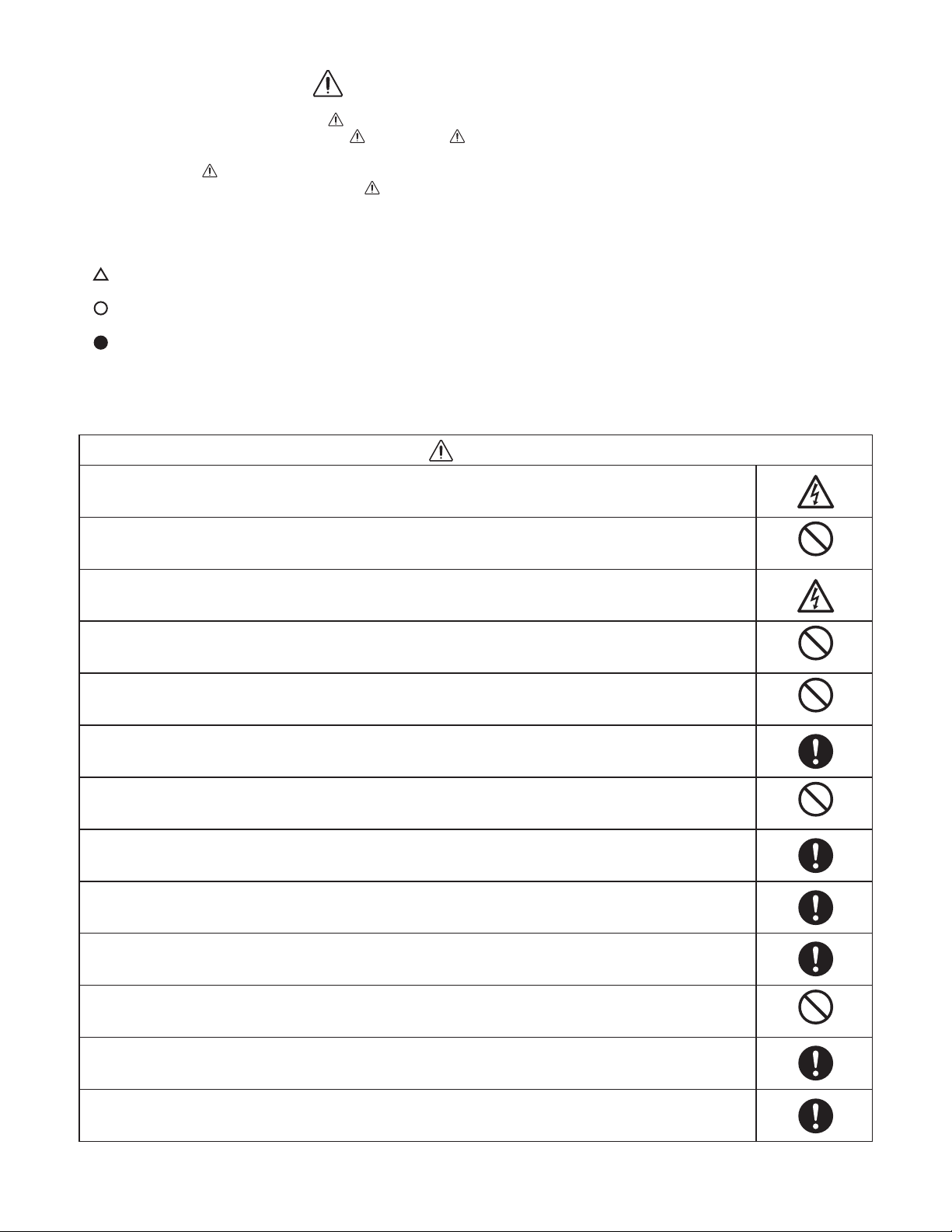
SAFETY PRECAUTIONS
• Before doing repair work, please read the " SAFETY PRECAUTIONS" carefully and fully understand them.
• The precautionary items here are divided into " Warning" and " Caution" items.
Items in particular which may cause death or serious injury to the service personnel if the work is not performed correctly,
are included in the " Warning" table.
However, even precautionary items identified as " Caution" also have the potential for serious consequences
if not performed correctly.
Important safety precautions are described for all items in both categories. Be sure to carefully follow all of them.
• Symbol Indication
: This symbol indicates items to which we need to pay attention.
In this triangle, a definite precautionary item is described.
: This symbol indicates the item to be prohibited.
In or close to this circle, a prohibited item is described.
: This symbol indicates the items requiring special attention or instruction.
In or close to this circle, a prohibited item is described.
• After doing repair work, perform a test run to confirm that there are no abnormalities.
At the same time, explain the precautions in use to the user.
Warning
Before performing an overhaul, disconnect the power plug or power cable from the unit.
Performing the work with the power supplied to the unit, may cause an electric shock.
When repair work or circuit inspection that requires power supply for the air conditioner, is to be performed,
do not touch the charging section.
Doing so may cause an electric shock.
Prohibit
For the step-up capacitor attached to the electric section, perform the repair work after sufficiently discharging it.
Insufficient capacitor discharge may cause an electric shock.
Do not perform repair work on the electric sections with wet hands.
Doing so may cause an electric shock.
Do not start or stop the air conditioner by means of connecting or disconnecting the power plug.
Doing so may cause an electric shock or fire.
When conducting repair work only use components included in the parts list for the corresponding unit and perform
the work with the appropriate tools.
Incorrect or poor repair work may cause an electric shock or fire.
Never modify the unit.
Doing so may cause an electric shock or fire.
Perform all electric work according to local applicable regulations related to electrical equipment or interior wiring
regulation and make sure to use the exclusive circuit.
Insufficient capacity to the electric circuit or defective arrangement results may cause an electric shock or fire.
Make sure to replace any power cable or lead wire showing any signs of scratch or deterioration.
Failure to do so may cause an electric shock, overheating or fire.
Make sure that there is no dust on or slack in the power plug and insert fully into the socket.
Dust or incomplete connections may cause an electric shock or fire.
Do not damage or process the power cord, as it may cause an electric shock or fire.
Prohibit
Prohibit
Prohibit
Prohibit
For the wiring between the indoor unit and outdoor unit, securely fix the specified cable onto the terminal plate.
Poorly fixed wiring may cause a heat or fire.
After connecting the wiring between the indoor unit and outdoor unit, attach the terminal cover securely.
Incomplete attachment of the terminal cover may cause overheating or fire.
2
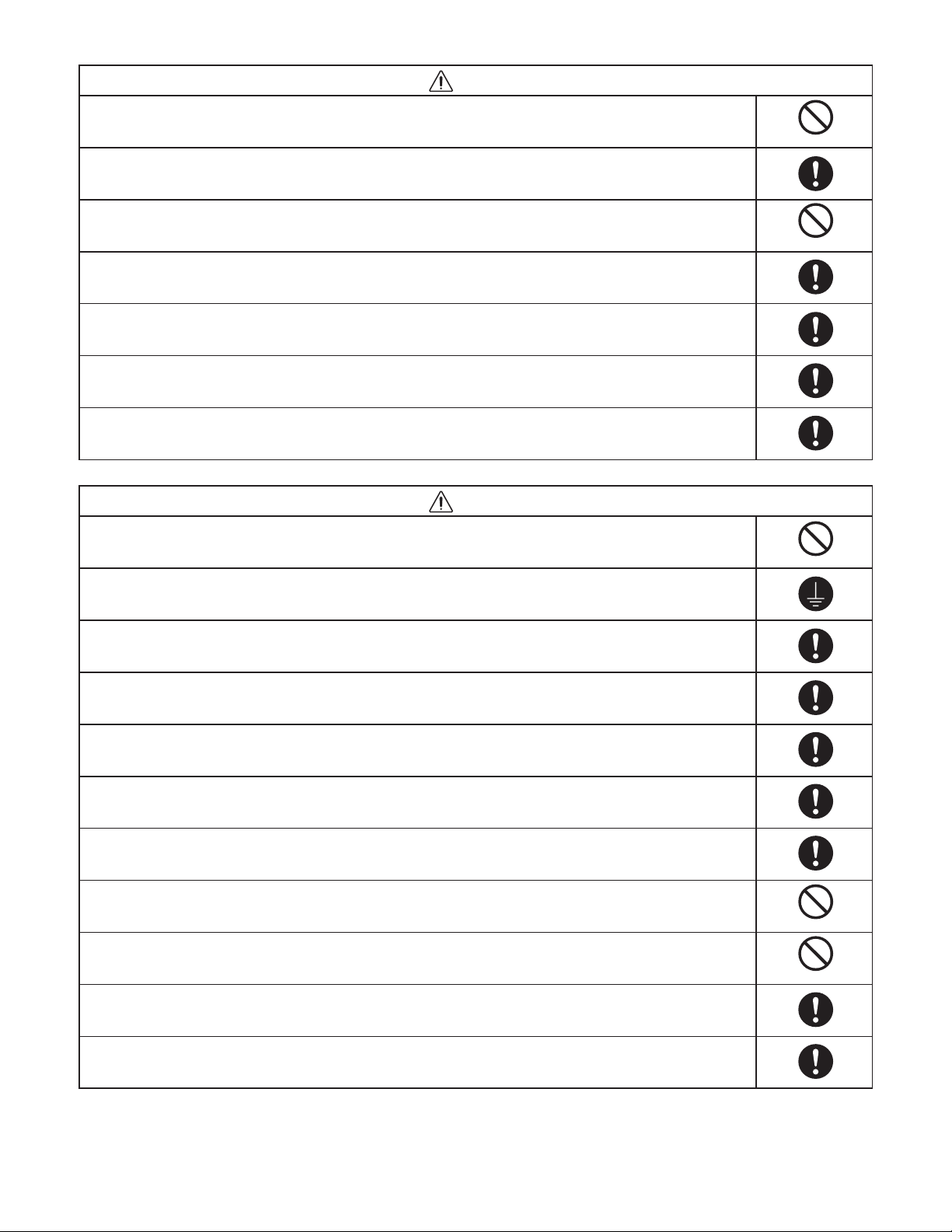
Warning
If refrigerant gas blows off during the work, do not touch the refrigerant gas as it may cause frostbite.
If refrigerant gas leaks during the work, ventilate the room.
If refrigerant gas catches fire, harmful gas may be generated.
Do not mix any gas other than the specified refrigerant gas in the refrigerating cycle.
If air or other contaminants mix with the gas, pressure will become extremely high in the refrigerating cycle,
which may cause a unit breakdown."
When the welded section of the compressor intake or discharge pipe is to be disconnected, perform it in
a well-ventilated place after sufficiently recovering the refrigerant gas.
Any residue gas may jet out refrigerant or refrigerating machine oil, which may cause an injury.
When the work is to be performed in a high place (About 2 meters or more), make sure to wear a safety helmet,
gloves and safety belt. Insufficient safety gear may cause a serious injury in case of a fall.
When the unit is to be relocated, confirm that the new installation location has sufficient strength for the weight of the unit.
Insufficient strength of the installation location and incomplete installation work may cause an injury due to
the unit falling.
When the remote controller batteries are replaced, dispose of the old batteries out of the reach of children.
If a child swallows a battery, make sure that the child gets immediate medical attention.
Caution
Prohibit
Prohibit
Do not wash the air conditioner with water, as this may cause an electric shock or fire.
For the repair work in places with high humidity or moisture, make sure to ground the unit.
Failure to do so may cause an electric shock.
Confirm that the component attachment position, wiring condition, soldering condition and connector connection
are normal.
If not, it may cause overheating or fire.
Confirm that the temperature around the compressor is not too high, and then perform the repair work.
Failure to do so may cause a burn.
Perform welding work in a place with good ventilation.
If the work is performed in a poorly ventilated area, it might cause a lack of oxygen.
If the installation plate or attachment frame has deteriorated due to corrosion, etc., replace it.
Failure to do so may cause an injury due to the unit falling.
When the cleaning is to be performed, make sure to turn off the power and pull out the plug.
Touching the fan that is rotating at high speed may result in an injury.
When the indoor unit is to be removed, do not place it on an incline.
Doing so may cause wet furniture because water left inside may trickle down.
Do not hold the sharp end of the unit or the aluminum fins, as it may cause an injury to your hand or finger.
Prohibit
Prohibit
Prohibit
After repairs, make sure to measure the insulation resistance and confirm that the value is 1 Mohm or more.
Any insulation error may cause an electric shock.
After repairs, make sure to check the drainage of the indoor unit.
Inappropriate drainage may cause wet furniture and floors due to water leakage.
3

Table of Contents
Page
SAFETY PRECAUTIONS
TABLE OF CONTENTS
APPLICABLE MULTI-OUTDOOR UNITS
1. OPERATING RANGE
2. SPECIFICATIONS
2-1. Unit Specifications
2-2. Major Component Specifications
2-3. Other Component Specifications
3. DIMENSIONAL DATA
4. REFRIGERANT FLOW DIAGRAM
4-1. Refrigerant Flow Diagram
5. PERFORMANCE DATA
5-1. Air Throw Distance Charts
.............................................................................................................
....................................................................................................................
...................................................................................................................
.............................................................................................................
....................................................................................................................
..................................................................................................
.................................................................................................
....................................................................................
.......................................................................................
.......................................................................................
2
4
5
6
7
17
22
23
25
26
6. ELECTRICAL DATA
6-1. Electric Wiring Diagrams
7. FUNCTIONS
7-1. Operation Functions
7-2. Protective Functions
8. TROUBLESHOOTING (BEFORE CALLING FOR SERVICE)
8-1. Precautions before Performing Inspection or Repair
8-2. Method of Self-Diagnostics
8-3. Checking the Indoor and Outdoor Units
8-4. Trouble Diagnosis of Fan Motor
8-5. Noise Malfunction and Electromagnetic Interference
APPENDIX A Operating Instructions
APPENDIX B Operating Instructions
APPENDIX C INSTALLATION INSTRUCTIONS
....................................................................................................
...........................................................................................................
...........................................................................................................
.................................................................................................
..............................................................................
..........................................................................................
..........................................................................................
..........................................................................................
..........................................................................
..........................................................
.........................................................
31
32
34
35
35
38
41
42
A-1
A-2
A-3
4
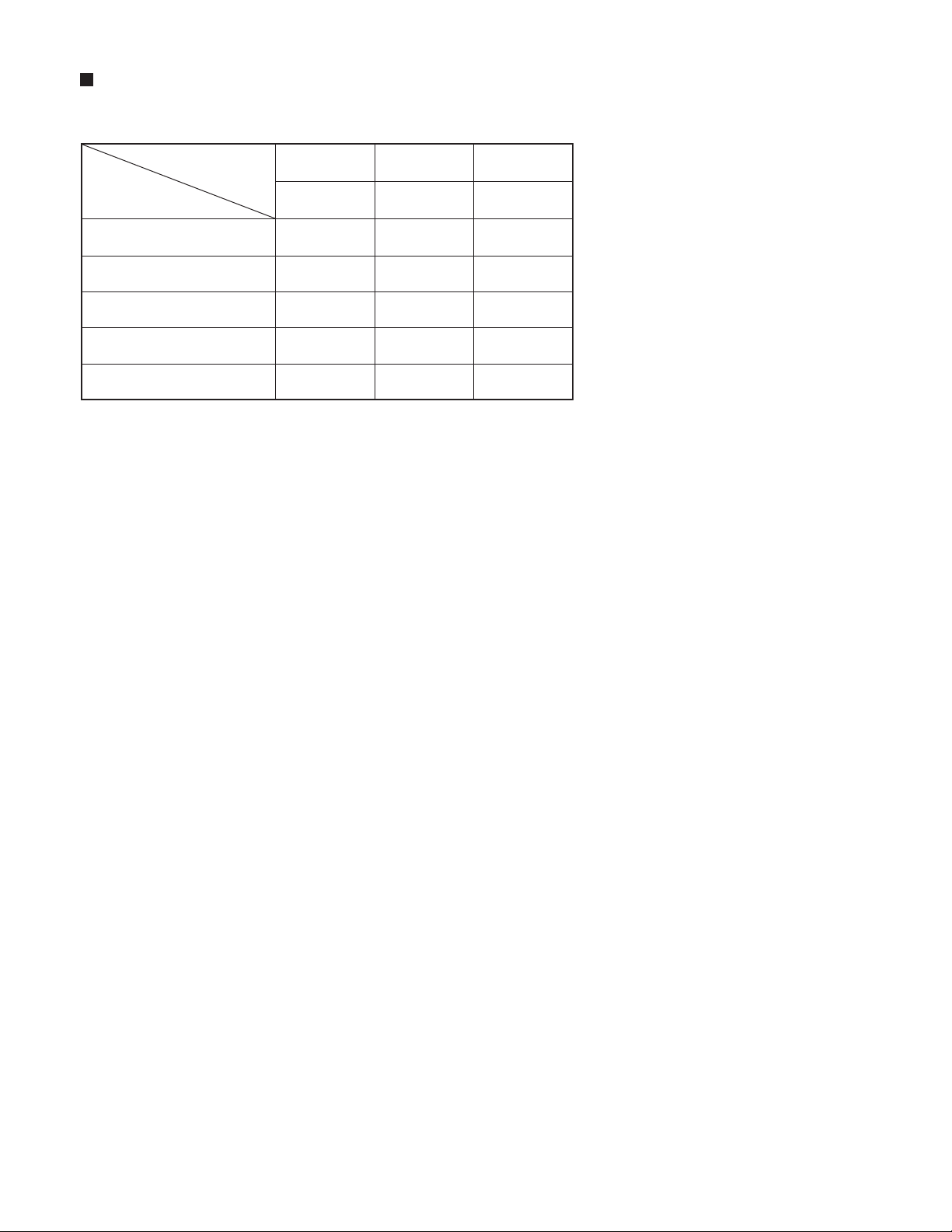
APPLICABLE MULTI-OUTDOOR UNITS
Multi-Outdoor Unit
Indoor Unit
CS-MKS7NKU
CS-MKS9NKU
CS-MKS12NKU
CS-MKS18NKU
CS-MKS24NKU
3-Room
CU-3KS19NBU
YES
YES
YES
YES
NO
4-Room
CU-4KS24NBU
YES
YES
YES
YES
YES
4-Room
CU-4KS31NBU
YES
YES
YES
YES
YES
5

1. OPERATING RANGE
Combination with cooling outdoor unit CU-3KS19NBU, CU-4KS24NBU or CU-4KS31NBU
Temperature Indoor Air Intake Temp. Outdoor Air Intake Temp.
Cooling
Maximum
Minimum
95 °F DB / 71 °F WB
67 °F DB / 57 °F WB
115 °F DB
14 °F DB
6

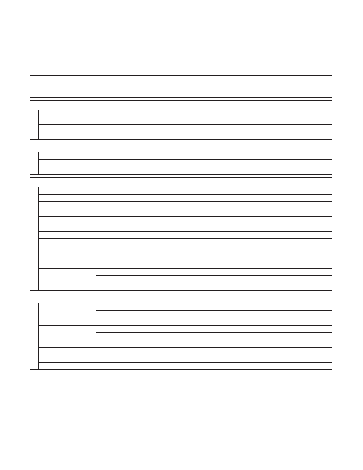
2. SPECIFICATIONS
2-1. Unit Specifications
Indoor Unit CS-MKS7NKU
Type Wall Mounted Type Indoor Unit
< 230V >
Voltage Rating
Performance
Capacity
Air Circulation (Hi/Me/Lo)
Moisture Removal (High)
Electrical Rating
Available Voltage Range
Running Amperes
Features
Control / Temperature Control
Control Unit
Timer
Airflow Direction (Indoor) Horizontal
Air Filter
Refrigerant
Operation Sound
(*Qt = Quiet mode)
Refrigerant Tubing Connections
Refrigerant inch (mm)
Tube Diameter inch (mm)
Refrigerant Tube Kit
Narrow tube
Wide tube
3
ft
/min (m3/h)
BTU/h
kW
Pints/h
WPower Input
Indoor Fan Speeds
Vertical
dB-AIndoor : Hi/Me/Lo/Qt*
230V Single-Phase 60Hz
Cooling
7,500
2.20
241 (410) / 224 (381) / 212 (360)
2.77
Cooling
V
A
Microprocessor / I.C. Thermistor
Wireless Remote Control Unit
24-Hour ON or OFF Timer, 1-Hour OFF Timer
187 to 253
0.11
25
Auto and 3 steps
Manual
Auto
Washable, Anti-Mold
R410A
33 / 30 / 27 / 23
Flare Type
1/4 (6.35)
3/8 (9.52)
Optional
Dimensions & Weight
Unit Dimensions Height
Package Dimensions
Weight
Shipping Volume
Width
Depth
Height
Width
Depth
Net
Shipping
inch (mm)
inch (mm)
inch (mm)
inch (mm)
inch (mm)
inch (mm)
Ib. (kg)
Ib. (kg)
cu.ft (m
Indoor Unit
11-7/32
32-15/32
7-7/16
10-19/32
35-21/32
14-1/32
3
)
DATA SUBJECT TO CHANGE WITHOUT NOTICE.
19.8
24.3
2.82
(285)
(825)
(189)
(269)
(906)
(356)
(9.0)
(11.
(0.08)
0)
7

Indoor Unit CS-MKS7NKU
Type Wall Mounted Type Indoor Unit
< 208V >
Voltage Rating
Performance
Capacity
Air Circulation (Hi/Me/Lo)
3
ft
/min (m3/h)
Moisture Removal (High)
Electrical Rating
Available Voltage Range
Running Amperes
Features
Control / Temperature Control
Control Unit
Timer
Airflow Direction (Indoor) Horizontal
Air Filter
Refrigerant
Operation Sound
(*Qt = Quiet mode)
Refrigerant Tubing Connections
Refrigerant inch (mm)
Tube Diameter inch (mm)
Refrigerant Tube Kit
Narrow tube
Wide tube
208V Single-Phase 60Hz
Cooling
BTU/h
kW
7,500
2.20
241 (410) / 224 (381) / 212 (360)
Pints/h
2.77
Cooling
V
A
WPower Input
187 to 253
0.12
25
Microprocessor / I.C. Thermistor
Wireless Remote Control Unit
24-Hour ON or OFF Timer, 1-Hour OFF Timer
Indoor Fan Speeds Auto and 3 steps
Manual
Vertical
Auto
Washable, Anti-Mold
R410A
dB-AIndoor : Hi/Me/Lo/Qt*
33 / 30 / 27 / 23
Flare Type
1/4 (6.35)
3/8 (9.52)
Optional
Dimensions & Weight
Unit Dimensions Height
Package Dimensions
Weight
Shipping Volume
Width
Depth
Height
Width
Depth
Net
Shipping
inch (mm)
inch (mm)
inch (mm)
inch (mm)
inch (mm)
inch (mm)
Ib. (kg)
Ib. (kg)
cu.ft (m
Indoor Unit
11-7/32
32-15/32
7-7/16
10-19/32
35-21/32
14-1/32
3
)
19.8
24.3
2.82
(285)
(825)
(189)
(269)
(906)
(356)
(9.0)
(11.0)
(0.08)
DATA SUBJECT TO CHANGE WITHOUT NOTICE.
8

Indoor Unit CS-MKS9NKU
Type Wall Mounted Type Indoor Unit
< 230V >
Voltage Rating
Performance
Capacity
Air Circulation (Hi/Me/Lo)
3
ft
/min (m3/h)
Moisture Removal (High)
Electrical Rating
Available Voltage Range
Running Amperes
Features
Control / Temperature Control
Control Unit
Timer
Airflow Direction (Indoor) Horizontal
Air Filter
Refrigerant
Operation Sound
(*Qt = Quiet mode)
Refrigerant Tubing Connections
Refrigerant inch (mm)
Tube Diameter inch (mm)
Refrigerant Tube Kit
Narrow tube
Wide tube
230V Single-Phase 60Hz
Cooling
BTU/h
kW
9,000
2.65
259 (440) / 241 (410) / 212 (360)
Pints/h
3.4
Cooling
V
A
WPower Input
187 to 253
0.15
35
Microprocessor / I.C. Thermistor
Wireless Remote Control Unit
24-Hour ON or OFF Timer, 1-Hour OFF Timer
Indoor Fan Speeds Auto and 3 steps
Manual
Vertical
Auto
Washable, Anti-Mold
R410A
dB-AIndoor : Hi/Me/Lo/Qt*
34 / 31 / 28 / 23
Flare Type
1/4 (6.35)
3/8 (9.52)
Optional
Dimensions & Weight
Unit Dimensions Height
Package Dimensions
Weight
Shipping Volume
Width
Depth
Height
Width
Depth
Net
Shipping
inch (mm)
inch (mm)
inch (mm)
inch (mm)
inch (mm)
inch (mm)
Ib. (kg)
Ib. (kg)
cu.ft (m
Indoor Unit
11-7/32
32-15/32
7-7/16
10-19/32
35-21/32
14-1/32
3
)
19.8
24.3
2.82
(285)
(825)
(189)
(269)
(906)
(356)
(9.0)
(11.0)
(0.08)
DATA SUBJECT TO CHANGE WITHOUT NOTICE.
9

Indoor Unit CS-MKS9NKU
Type Wall Mounted Type Indoor Unit
< 208V >
Voltage Rating
Performance
Capacity
Air Circulation (Hi/Me/Lo)
3
ft
/min (m3/h)
Moisture Removal (High)
Electrical Rating
Available Voltage Range
Running Amperes
Features
Control / Temperature Control
Control Unit
Timer
Airflow Direction (Indoor) Horizontal
Air Filter
Refrigerant
Operation Sound
(*Qt = Quiet mode)
Refrigerant Tubing Connections
Refrigerant inch (mm)
Tube Diameter inch (mm)
Refrigerant Tube Kit
Narrow tube
Wide tube
208V Single-Phase 60Hz
Cooling
BTU/h
kW
9,000
2.65
259 (440) / 241 (410) / 212 (360)
Pints/h
3.4
Cooling
V
A
WPower Input
187 to 253
0.17
35
Microprocessor / I.C. Thermistor
Wireless Remote Control Unit
24-Hour ON or OFF Timer, 1-Hour OFF Timer
Indoor Fan Speeds Auto and 3 steps
Manual
Vertical
Auto
Washable, Anti-Mold
R410A
dB-AIndoor : Hi/Me/Lo/Qt*
34 / 31 / 28 / 23
Flare Type
1/4 (6.35)
3/8 (9.52)
Optional
Dimensions & Weight
Unit Dimensions Height
Package Dimensions
Weight
Shipping Volume
Width
Depth
Height
Width
Depth
Net
Shipping
inch (mm)
inch (mm)
inch (mm)
inch (mm)
inch (mm)
inch (mm)
Ib. (kg)
Ib. (kg)
cu.ft (m
Indoor Unit
11-7/32
32-15/32
7-7/16
10-19/32
35-21/32
14-1/32
3
)
19.8
24.3
2.82
(285)
(825)
(189)
(269)
(906)
(356)
(9.0)
(11.0)
(0.08)
DATA SUBJECT TO CHANGE WITHOUT NOTICE.
10

Indoor Unit CS-MKS12NKU
Type Wall Mounted Type Indoor Unit
< 230V >
Voltage Rating
Performance
Capacity
Air Circulation (Hi/Me/Lo)
3
ft
/min (m3/h)
Moisture Removal (High)
Electrical Rating
Available Voltage Range
Running Amperes
Features
Control / Temperature Control
Control Unit
Timer
Airflow Direction (Indoor) Horizontal
Air Filter
Refrigerant
Operation Sound
(*Qt = Quiet mode)
Refrigerant Tubing Connections
Refrigerant inch (mm)
Tube Diameter inch (mm)
Refrigerant Tube Kit
Narrow tube
Wide tube
230V Single-Phase 60Hz
Cooling
BTU/h
kW
11,900
3.50
282 (479) / 259 (440) / 218 (370)
Pints/h
4.26
Cooling
V
A
WPower Input
187 to 253
0.15
35
Microprocessor / I.C. Thermistor
Wireless Remote Control Unit
24-Hour ON or OFF Timer, 1-Hour OFF Timer
Indoor Fan Speeds Auto and 3 steps
Manual
Vertical
Auto
Washable, Anti-Mold
R410A
dB-AIndoor : Hi/Me/Lo/Qt*
36 / 33 / 29 / 25
Flare Type
1/4 (6.35)
3/8 (9.52)
Optional
Dimensions & Weight
Unit Dimensions Height
Package Dimensions
Weight
Shipping Volume
Width
Depth
Height
Width
Depth
Net
Shipping
inch (mm)
inch (mm)
inch (mm)
inch (mm)
inch (mm)
inch (mm)
Ib. (kg)
Ib. (kg)
cu.ft (m
Indoor Unit
11-7/32
32-15/32
7-7/16
10-19/32
35-21/32
14-1/32
3
)
19.8
24.3
2.82
(285)
(825)
(189)
(269)
(906)
(356)
(9.0)
(11.0)
(0.08)
DATA SUBJECT TO CHANGE WITHOUT NOTICE.
11

Indoor Unit CS-MKS12NKU
Type Wall Mounted Type Indoor Unit
< 208V >
Voltage Rating
Performance
Capacity
Air Circulation (Hi/Me/Lo)
3
ft
/min (m3/h)
Moisture Removal (High)
Electrical Rating
Available Voltage Range
Running Amperes
Features
Control / Temperature Control
Control Unit
Timer
Airflow Direction (Indoor) Horizontal
Air Filter
Refrigerant
Operation Sound
(*Qt = Quiet mode)
Refrigerant Tubing Connections
Refrigerant inch (mm)
Tube Diameter inch (mm)
Refrigerant Tube Kit
Narrow tube
Wide tube
208V Single-Phase 60Hz
Cooling
BTU/h
kW
11,900
3.50
282 (479) / 259 (440) / 218 (370)
Pints/h
4.26
Cooling
V
A
WPower Input
187 to 253
0.17
35
Microprocessor / I.C. Thermistor
Wireless Remote Control Unit
24-Hour ON or OFF Timer, 1-Hour OFF Timer
Indoor Fan Speeds Auto and 3 steps
Manual
Vertical
Auto
Washable, Anti-Mold
R410A
dB-AIndoor : Hi/Me/Lo/Qt*
36 / 33 / 29 / 25
Flare Type
1/4 (6.35)
3/8 (9.52)
Optional
Dimensions & Weight
Unit Dimensions Height
Package Dimensions
Weight
Shipping Volume
Width
Depth
Height
Width
Depth
Net
Shipping
inch (mm)
inch (mm)
inch (mm)
inch (mm)
inch (mm)
inch (mm)
Ib. (kg)
Ib. (kg)
cu.ft (m
Indoor Unit
11-7/32
32-15/32
7-7/16
10-19/32
35-21/32
14-1/32
3
)
19.8
24.3
2.82
(285)
(825)
(189)
(269)
(906)
(356)
(9.0)
(11.0)
(0.08)
DATA SUBJECT TO CHANGE WITHOUT NOTICE.
12

Indoor Unit CS-MKS18NKU
Type Wall Mounted Type Indoor Unit
< 230V >
Voltage Rating
Performance
Capacity
Air Circulation (Hi/Me/Lo)
3
ft
/min (m3/h)
Moisture Removal (High)
Electrical Rating
Available Voltage Range
Running Amperes
Features
Control / Temperature Control
Control Unit
Timer
Airflow Direction (Indoor) Horizontal
Air Filter
Refrigerant
Operation Sound
(*Qt = Quiet mode)
Refrigerant Tubing Connections
Refrigerant inch (mm)
Tube Diameter inch (mm)
Refrigerant Tube Kit
Narrow tube
Wide tube
230V Single-Phase 60Hz
Cooling
BTU/h
kW
17,500
5.15
500 (850) / 447 (760) / 377 (641)
Pints/h
4.89
Cooling
V
A
WPower Input
187 to 253
0.15
35
Microprocessor / I.C. Thermistor
Wireless Remote Control Unit
24-Hour ON or OFF Timer, 1-Hour OFF Timer
Indoor Fan Speeds Auto and 3 steps
Manual
Vertical
Auto
Washable, Anti-Mold
R410A
dB-AIndoor : Hi/Me/Lo/Qt*
41 / 38 / 34 / 28
Flare Type
1/4 (6.35)
1/2 (12.7)
Optional
Dimensions & Weight
Unit Dimensions Height
Package Dimensions
Weight
Shipping Volume
Width
Depth
Height
Width
Depth
Net
Shipping
inch (mm)
inch (mm)
inch (mm)
inch (mm)
inch (mm)
inch (mm)
Ib. (kg)
Ib. (kg)
cu.ft (m
Indoor Unit
11-23/32
41-15/16
11-27/32
45-1/8
15-5/32
3
)
8-5/8
26.5
33.1
4.59
(298)
(1,065)
(219)
(301)
(1,146)
(385)
(12.0)
(15.
0)
(0.13)
DATA SUBJECT TO CHANGE WITHOUT NOTICE.
13

Indoor Unit CS-MKS18NKU
Type Wall Mounted Type Indoor Unit
< 208V >
Voltage Rating
Performance
Capacity
Air Circulation (Hi/Me/Lo)
3
ft
/min (m3/h)
Moisture Removal (High)
Electrical Rating
Available Voltage Range
Running Amperes
Features
Control / Temperature Control
Control Unit
Timer
Airflow Direction (Indoor) Horizontal
Air Filter
Refrigerant
Operation Sound
(*Qt = Quiet mode)
Refrigerant Tubing Connections
Refrigerant inch (mm)
Tube Diameter inch (mm)
Refrigerant Tube Kit
Narrow tube
Wide tube
208V Single-Phase 60Hz
Cooling
BTU/h
kW
17,500
5.15
500 (850) / 447 (760) / 377 (641)
Pints/h
4.89
Cooling
V
A
WPower Input
187 to 253
0.17
35
Microprocessor / I.C. Thermistor
Wireless Remote Control Unit
24-Hour ON or OFF Timer, 1-Hour OFF Timer
Indoor Fan Speeds Auto and 3 steps
Manual
Vertical
Auto
Washable, Anti-Mold
R410A
dB-AIndoor : Hi/Me/Lo/Qt*
41 / 38 / 34 / 28
Flare Type
1/4 (6.35)
1/2 (12.7)
Optional
Dimensions & Weight
Unit Dimensions Height
Package Dimensions
Weight
Shipping Volume
Width
Depth
Height
Width
Depth
Net
Shipping
inch (mm)
inch (mm)
inch (mm)
inch (mm)
inch (mm)
inch (mm)
Ib. (kg)
Ib. (kg)
cu.ft (m
Indoor Unit
11-23/32
41-15/16
11-27/32
45-1/8
15-5/32
3
)
8-5/8
26.5
33.1
4.59
(298)
(1,065)
(219)
(301)
(1,146)
(385)
(12.0)
(15.0)
(0.13)
DATA SUBJECT TO CHANGE WITHOUT NOTICE.
14
Indoor Unit CS-MKS24NKU
Type Wall Mounted Type Indoor Unit
< 230V >
Voltage Rating
Performance
Capacity
Air Circulation (Hi/Me/Lo)
3
ft
/min (m3/h)
Moisture Removal (High)
Electrical Rating
Available Voltage Range
Running Amperes
Features
Control / Temperature Control
Control Unit
Timer
Airflow Direction (Indoor) Horizontal
Air Filter
Refrigerant
Operation Sound
(*Qt = Quiet mode)
Refrigerant Tubing Connections
Refrigerant inch (mm)
Tube Diameter inch (mm)
Refrigerant Tube Kit
Narrow tube
Wide tube
230V Single-Phase 60Hz
Cooling
BTU/h
kW
24,200
7.10
541 (919) / 500 (850) / 435 (739)
Pints/h
4.89
Cooling
V
A
WPower Input
187 to 253
0.20
45
Microprocessor / I.C. Thermistor
Wireless Remote Control Unit
24-Hour ON or OFF Timer, 1-Hour OFF Timer
Indoor Fan Speeds Auto and 3 steps
Manual
Vertical
Auto
Washable, Anti-Mold
R410A
dB-AIndoor : Hi/Me/Lo/Qt*
44 / 41 / 38 / 30
Flare Type
1/4 (6.35)
5/8 (15.88)
Optional
Dimensions & Weight
Unit Dimensions Height
Package Dimensions
Weight
Shipping Volume
Width
Depth
Height
Width
Depth
Net
Shipping
inch (mm)
inch (mm)
inch (mm)
inch (mm)
inch (mm)
inch (mm)
Ib. (kg)
Ib. (kg)
cu.ft (m
Indoor Unit
11-23/32
41-15/16
11-27/32
45-1/8
15-5/32
3
)
8-5/8
26.5
33.1
4.59
(298)
(1,065)
(219)
(301)
(1,146)
(385)
(12.0)
(15.0)
(0.13)
DATA SUBJECT TO CHANGE WITHOUT NOTICE.
15

Indoor Unit CS-MKS24NKU
Type Wall Mounted Type Indoor Unit
< 208V >
Voltage Rating
Performance
Capacity
Air Circulation (Hi/Me/Lo)
3
ft
/min (m3/h)
Moisture Removal (High)
Electrical Rating
Available Voltage Range
Running Amperes
Features
Control / Temperature Control
Control Unit
Timer
Airflow Direction (Indoor) Horizontal
Air Filter
Refrigerant
Operation Sound
(*Qt = Quiet mode)
Refrigerant Tubing Connections
Refrigerant inch (mm)
Tube Diameter inch (mm)
Refrigerant Tube Kit
Narrow tube
Wide tube
208V Single-Phase 60Hz
Cooling
BTU/h
kW
24,200
7.10
541 (919) / 500 (850) / 435 (739)
Pints/h
4.89
Cooling
V
A
WPower Input
187 to 253
0.22
45
Microprocessor / I.C. Thermistor
Wireless Remote Control Unit
24-Hour ON or OFF Timer, 1-Hour OFF Timer
Indoor Fan Speeds Auto and 3 steps
Manual
Vertical
Auto
Washable, Anti-Mold
R410A
dB-AIndoor : Hi/Me/Lo/Qt*
44 / 41 / 38 / 30
Flare Type
1/4 (6.35)
5/8 (15.88)
Optional
Dimensions & Weight
Unit Dimensions Height
Package Dimensions
Weight
Shipping Volume
Width
Depth
Height
Width
Depth
Net
Shipping
inch (mm)
inch (mm)
inch (mm)
inch (mm)
inch (mm)
inch (mm)
Ib. (kg)
Ib. (kg)
cu.ft (m
Indoor Unit
8-5/8
26.5
33.1
4.59
(298)
(1,065)
(219)
(301)
(1,146)
(385)
(12.0)
(15.0)
(0.13)
11-23/32
41-15/16
11-27/32
45-1/8
15-5/32
3
)
DATA SUBJECT TO CHANGE WITHOUT NOTICE.
16

2-2. Major Component Specifications
2-2-1. Indoor Unit
Indoor Unit CS-MKS7NKU
Control PCB
Part No.
Controls
Control Circuit Fuse
Fan
Type
Q'ty ... Dia. and Length
Fan Motor
Type
Model ... Q'ty
No. of Poles
Rough Measure RPM (Cool)
Nominal Output
Coil Resistance
(Ambient Temp. 68 °F (20 °C))
Safety Device
Type
Over- Current Protection
Over-Heat Protection
Run Capacitor Micro F
inch (mm)
W
Ohm
VAC
CB-CU-MKS7NKU
Microprocessor
250V 3A
Cross-Flow
1 ... D3-5/8 / L24-31/32 (D92 / L634)
DC Motor
SIC-41CVJ-D847-4 ... 1
8
1,050
47
-
Internal Controller
Yes
Yes
-
-
Flap Motor
Type Stepping Motor
Model MP24Z3
Rating DC 12V
Coil Resistance Ohm Each Pair of Terminal : 400 +/- 7%
(Ambient Temp. 77 °F (25 °C))
Heat Exchanger Coil
Coil
Rows
Fins per inch
ft
2
(m2)
Aluminum Plate Fin / Copper Tube
2
19.5
2.02 (0.188) Face Area
DATA SUBJECT TO CHANGE WITHOUT NOTICE.
17
Indoor Unit CS-MKS9NKU
Control PCB
Part No.
Controls
Control Circuit Fuse
Fan
Type
Q'ty ... Dia. and Length
Fan Motor
Type
Model ... Q'ty
No. of Poles
Rough Measure RPM (Cool)
Nominal Output
Coil Resistance
(Ambient Temp. 68 °F (20 °C))
Safety Device
Type
Over- Current Protection
Over-Heat Protection
Run Capacitor Micro F
inch (mm)
W
Ohm
VAC
CB-CU-MKS9NKU
Microprocessor
250V 3A
Cross-Flow
1 ... D3-5/8 / L24-31/32 (D92 / L634)
DC Motor
SIC-41CVJ-D847-4 ... 1
8
1,100
47
-
Internal Controller
Yes
Yes
-
-
Flap Motor
Type Stepping Motor
Model MP24Z3
Rating DC 12V
Coil Resistance Ohm Each Pair of Terminal : 400 +/- 7%
(Ambient Temp. 77 °F (25 °C))
Heat Exchanger Coil
Coil
Rows
Fins per inch
ft
2
(m2)
Aluminum Plate Fin / Copper Tube
2
19.5
2.02 (0.188) Face Area
DATA SUBJECT TO CHANGE WITHOUT NOTICE.
18

Indoor Unit CS-MKS12NKU
Control PCB
Part No.
Controls
Control Circuit Fuse
Fan
Type
Q'ty ... Dia. and Length
Fan Motor
Type
Model ... Q'ty
No. of Poles
Rough Measure RPM (Cool)
Nominal Output
Coil Resistance
(Ambient Temp. 68 °F (20 °C))
Safety Device
Type
Over- Current Protection
Over-Heat Protection
Run Capacitor Micro F
inch (mm)
W
Ohm
VAC
CB-CU-MKS12NKU
Microprocessor
250V 3A
Cross-Flow
1 ... D3-5/8 / L24-31/32 (D92 / L634)
DC Motor
SIC-41CVJ-D847-4 ... 1
8
1,200
47
-
Internal Controller
Yes
Yes
-
-
Flap Motor
Type Stepping Motor
Model MP24Z3
Rating DC 12V
Coil Resistance Ohm Each Pair of Terminal : 400 +/- 7%
(Ambient Temp. 77 °F (25 °C))
Heat Exchanger Coil
Coil
Rows
Fins per inch
ft
2
(m2)
Aluminum Plate Fin / Copper Tube
2
19.5
2.02 (0.188) Face Area
DATA SUBJECT TO CHANGE WITHOUT NOTICE.
19

Indoor Unit CS-MKS18NKU
Control PCB
Part No.
Controls
Control Circuit Fuse
Fan
Type
Q'ty ... Dia. and Length
Fan Motor
Type
Model ... Q'ty
No. of Poles
Rough Measure RPM (Cool)
Nominal Output
Coil Resistance
(Ambient Temp. 68 °F (20 °C))
Safety Device
Type
Over- Current Protection
Over-Heat Protection
Run Capacitor Micro F
inch (mm)
W
Ohm
VAC
CB-CU-MKS18NKU
Microprocessor
250V 3A
Cross-Flow
1 ... D3-5/8 / L33-9/32 (D92 / L845)
DC Motor
SIC-41CVJ-D847-3 ... 1
8
1,200
30
-
Internal Controller
Yes
Yes
-
-
Flap Motor
Type Stepping Motor
Model MP24Z3
Rating DC 12V
Coil Resistance Ohm Each Pair of Terminal : 400 +/- 7%
(Ambient Temp. 77 °F (25 °C))
Heat Exchanger Coil
Coil
Rows
Fins per inch
ft
2
(m2)
Aluminum Plate Fin / Copper Tube
2
19.5
3.07 (0.285) Face Area
DATA SUBJECT TO CHANGE WITHOUT NOTICE.
20

Indoor Unit CS-MKS24NKU
Control PCB
Part No.
Controls
Control Circuit Fuse
Fan
Type
Q'ty ... Dia. and Length
Fan Motor
Type
Model ... Q'ty
No. of Poles
Rough Measure RPM (Cool)
Nominal Output
Coil Resistance
(Ambient Temp. 68 °F (20 °C))
Safety Device
Type
Over- Current Protection
Over-Heat Protection
Run Capacitor Micro F
inch (mm)
W
Ohm
VAC
CB-CU-MKS24NKU
Microprocessor
250V 3A
Cross-Flow
1 ... D3-5/8 / L33-9/32 (D92 / L845)
DC Motor
SIC-41CVJ-D847-3 ... 1
8
1,300
30
-
Internal Controller
Yes
Yes
-
-
Flap Motor
Type Stepping Motor
Model MP24Z3
Rating DC 12V
Coil Resistance Ohm Each Pair of Terminal : 400 +/- 7%
(Ambient Temp. 77 °F (25 °C))
Heat Exchanger Coil
Coil
Rows
Fins per inch
ft
2
(m2)
Aluminum Plate Fin / Copper Tube
2
19.5
3.07 (0.285) Face Area
DATA SUBJECT TO CHANGE WITHOUT NOTICE.
21
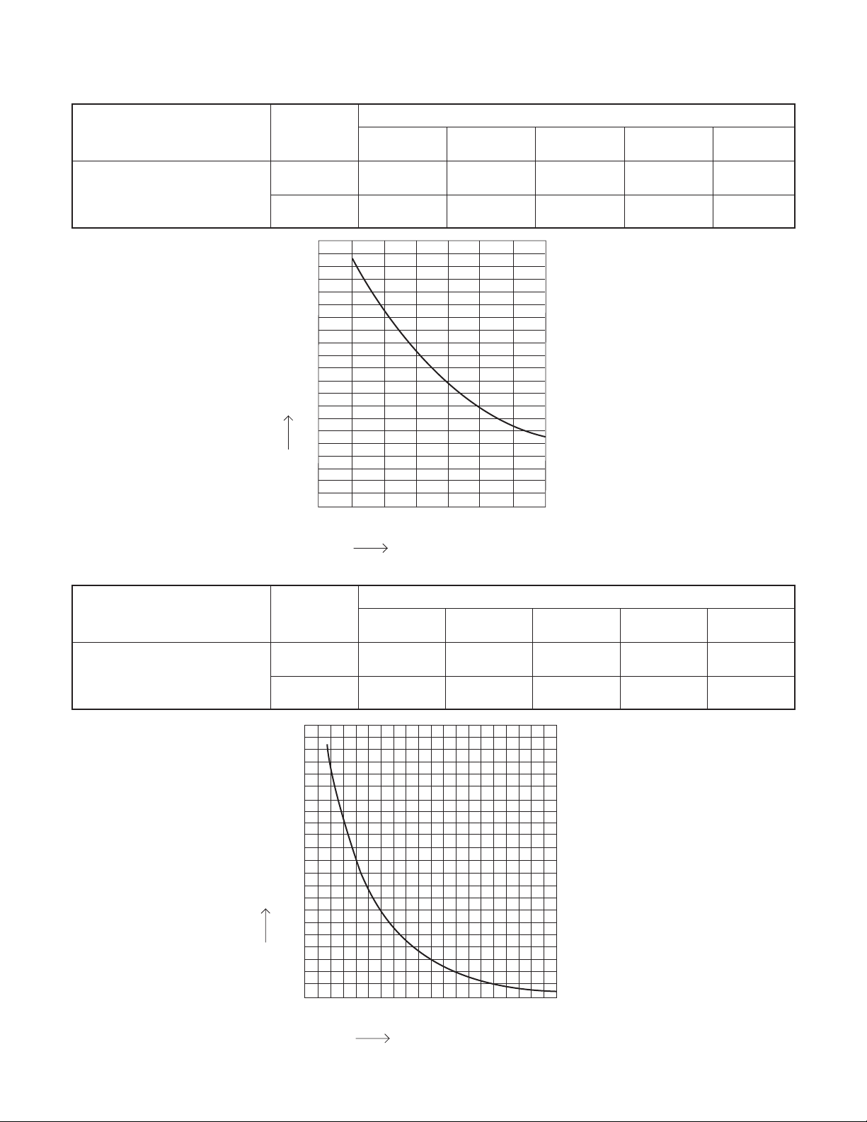
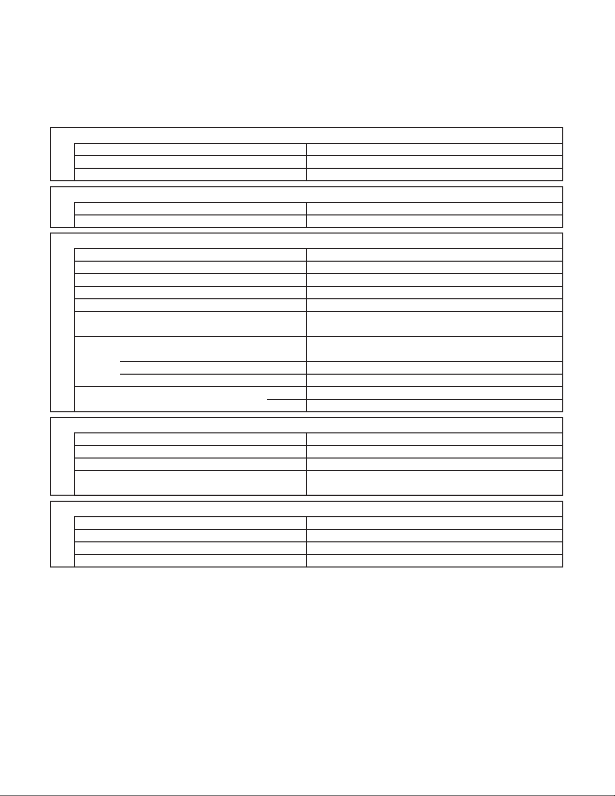
2-3. Other Component Specifications
Sensor Name
Indoor air temp sensor
Model No.
of sensor
PTM-D51HS3 TH2
PTM-D51HS3-2 TH2
10
9
8
7
6
5
Resistance (k ohm)
4
3
2
1
0
CS-MKS7NKU CS-MKS9NKU
50
(10) (15) (20) (25) (30) (35) (40)
Quantity of Sensor
CS-MKS12NKU CS-MKS18NKU
111
00011
59 68 77 86 95 104
Temperature °F (°C)
00
CS-MKS24NKU
Sensor Name
Indoor heat exchanger sensor
Model No.
of sensor
PTM-D51HS3 TH1
PTM-D51HS3-2 TH1
200
180
160
140
120
100
Resistance (k ohm)
80
60
40
20
0
CS-MKS7NKU CS-MKS9NKU
32 50 68 86 104 122 140 158 176 194
(0) (10) (20) (30) (40) (50) (60) (70)(80) (90)
Quantity of Sensor
CS-MKS12NKU CS-MKS18NKU
111
00011
Temperature °F (°C)
00
CS-MKS24NKU
22
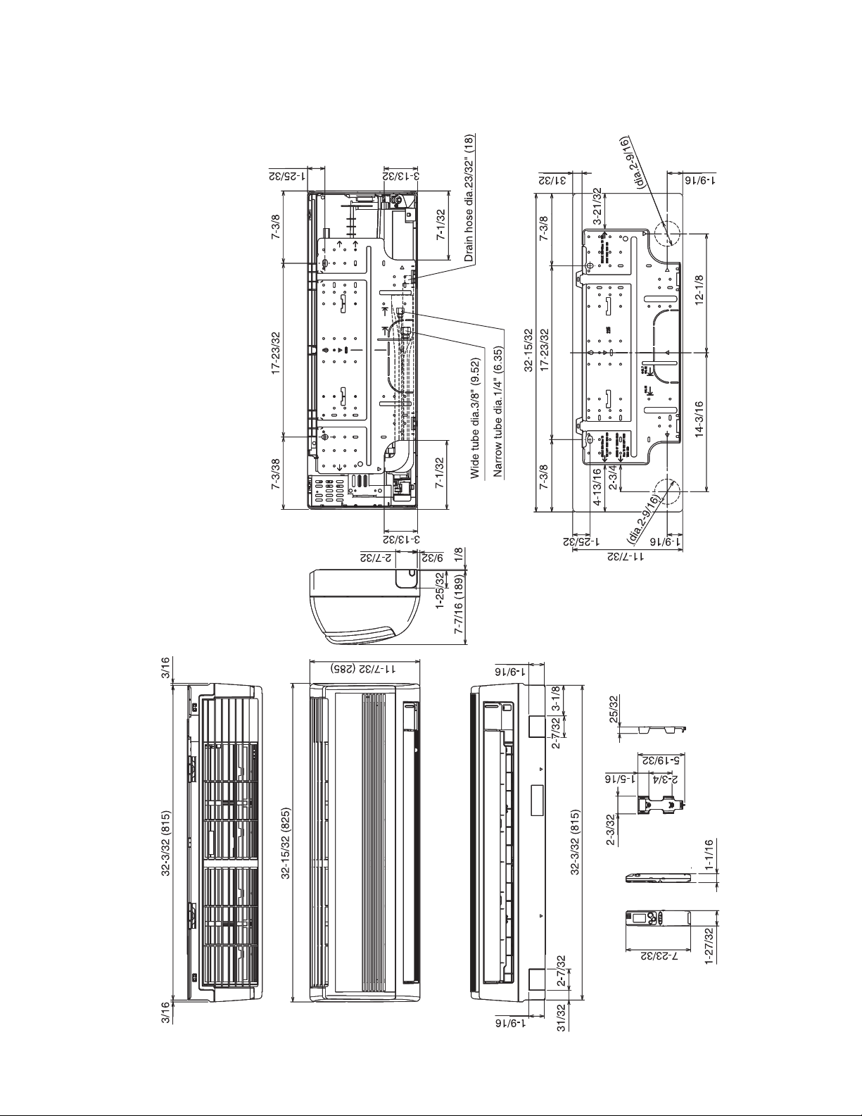
3. DIMENSIONAL DATA
Indoor Unit CS-MKS7NKU
CS-MKS9NKU
CS-MKS12NKU
23
Unit: inch(mm)
(852-0-0010-215-00-0)
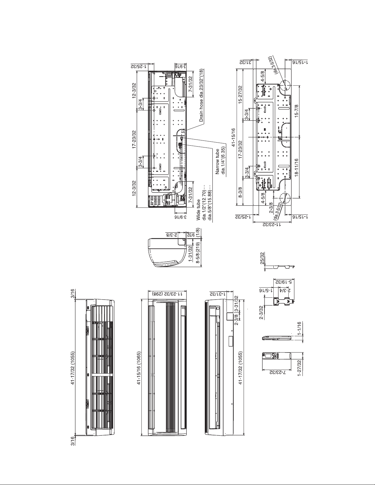
Indoor Unit CS-MKS18NKU
CS-MKS24NKU
CS-MKS18NKU
CS-MKS24NKU
24
Unit: inch(mm)
(852-0-0010-216-00-0)
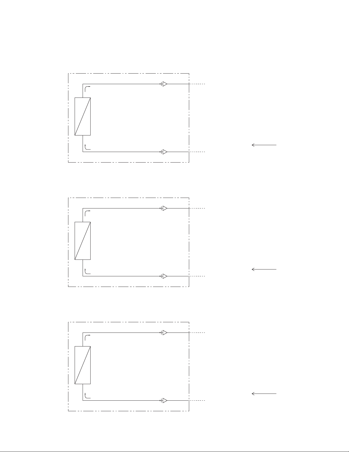
4. REFRIGERANT FLOW DIAGRAM
4-1. Refrigerant Flow Diagram
Indoor Unit CS-MKS7NKU
CS-MKS9NKU
CS-MKS12NKU
Indoor heat
exchanger
Indoor unit
O.D. 3/8" (9.52 mm)
Indoor Unit CS-MKS18NKU
Indoor heat
exchanger
Indoor Unit CS-MKS24NKU
Indoor unit
Indoor unit
O.D. 1/4" (6.35 mm)
O.D. 1/2" (12.7 mm)
O.D. 1/4" (6.35 mm)
Cooling cycle
Cooling cycle
Indoor heat
exchanger
25
O.D. 5/8" (15.88 mm)
O.D. 1/4" (6.35 mm)
Cooling cycle
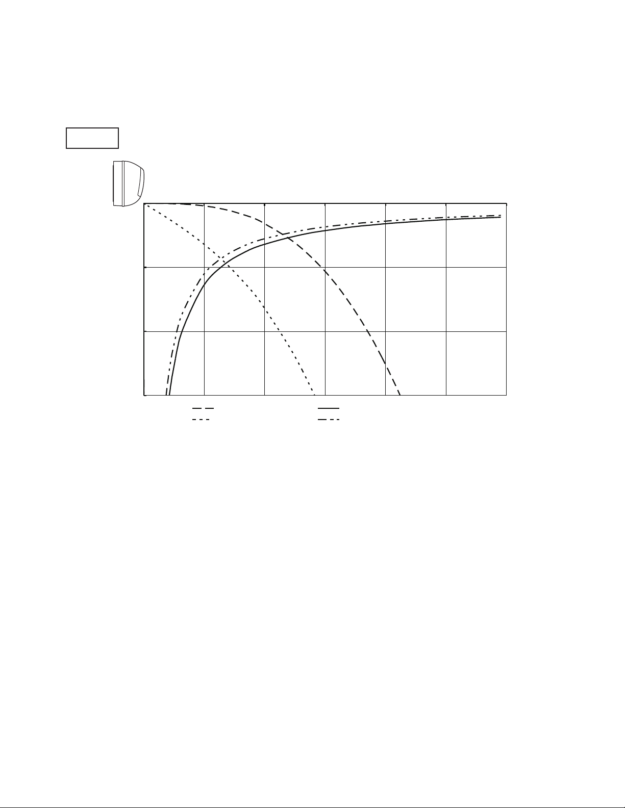
5. PERFORMANCE DATA
0
5
10
15
0 5 10 15 20 25 30
5-1. Air Throw Distance Charts
Indoor Unit CS-MKS7NKU
Cooling
Room air temp. : 80°F (26.7°C)
Fan speed : High
Axis air velocity (ft./sec.)
Vertical distance (ft.)
Horizontal distance (ft.)
: Flap angle 0° , : Axis air velocity 0
: Flap angle 30° , : Axis air velocity 30
°
°
26
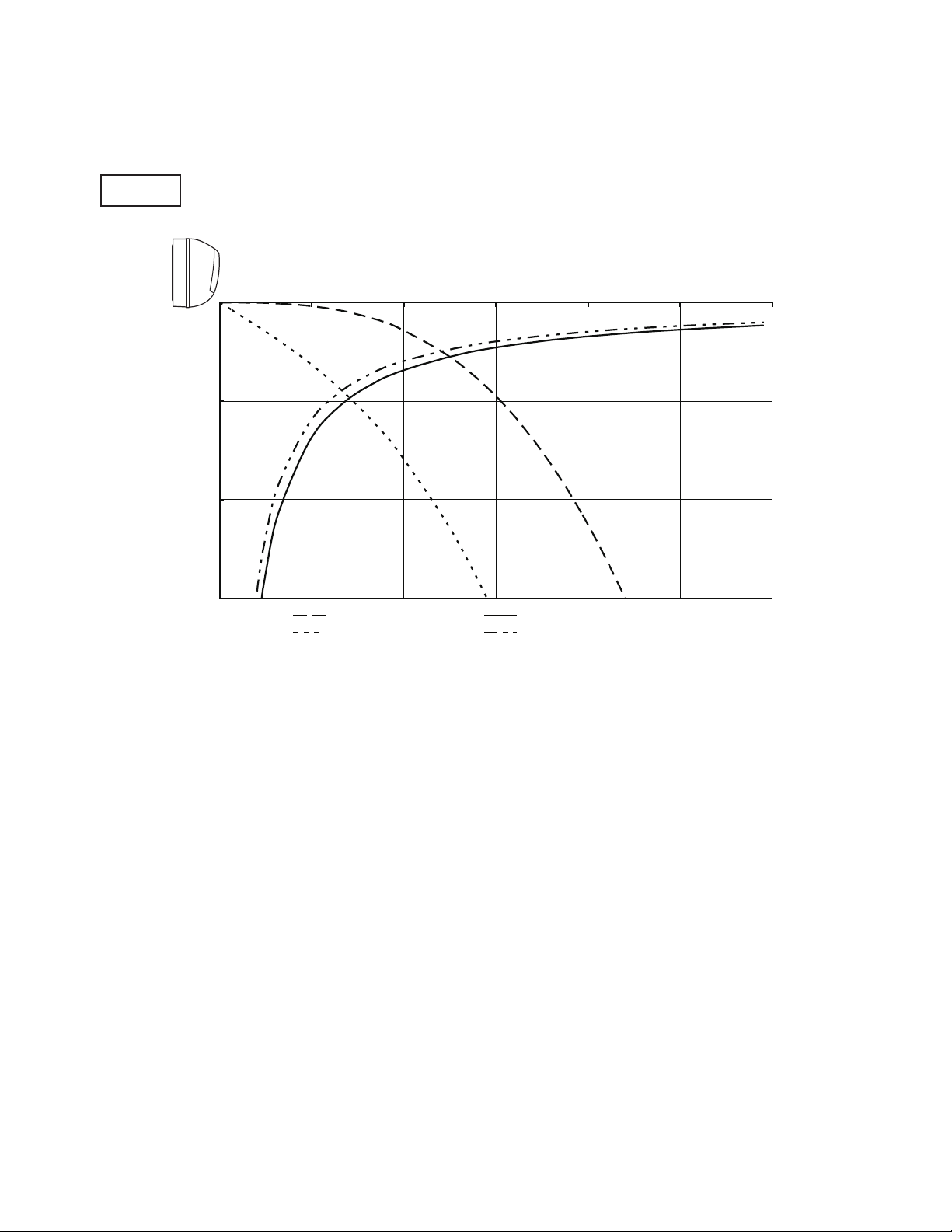
Indoor Unit CS-MKS9NKU
0
5
10
15
0 5 10 15 20 25 30
Cooling
Room air temp. : 80°F (26.7°C)
Fan speed : High
Axis air velocity (ft./sec.)
Vertical distance (ft.)
Horizontal distance (ft.)
: Flap angle 0° , : Axis air velocity 0
: Flap angle 30° , : Axis air velocity 30
°
°
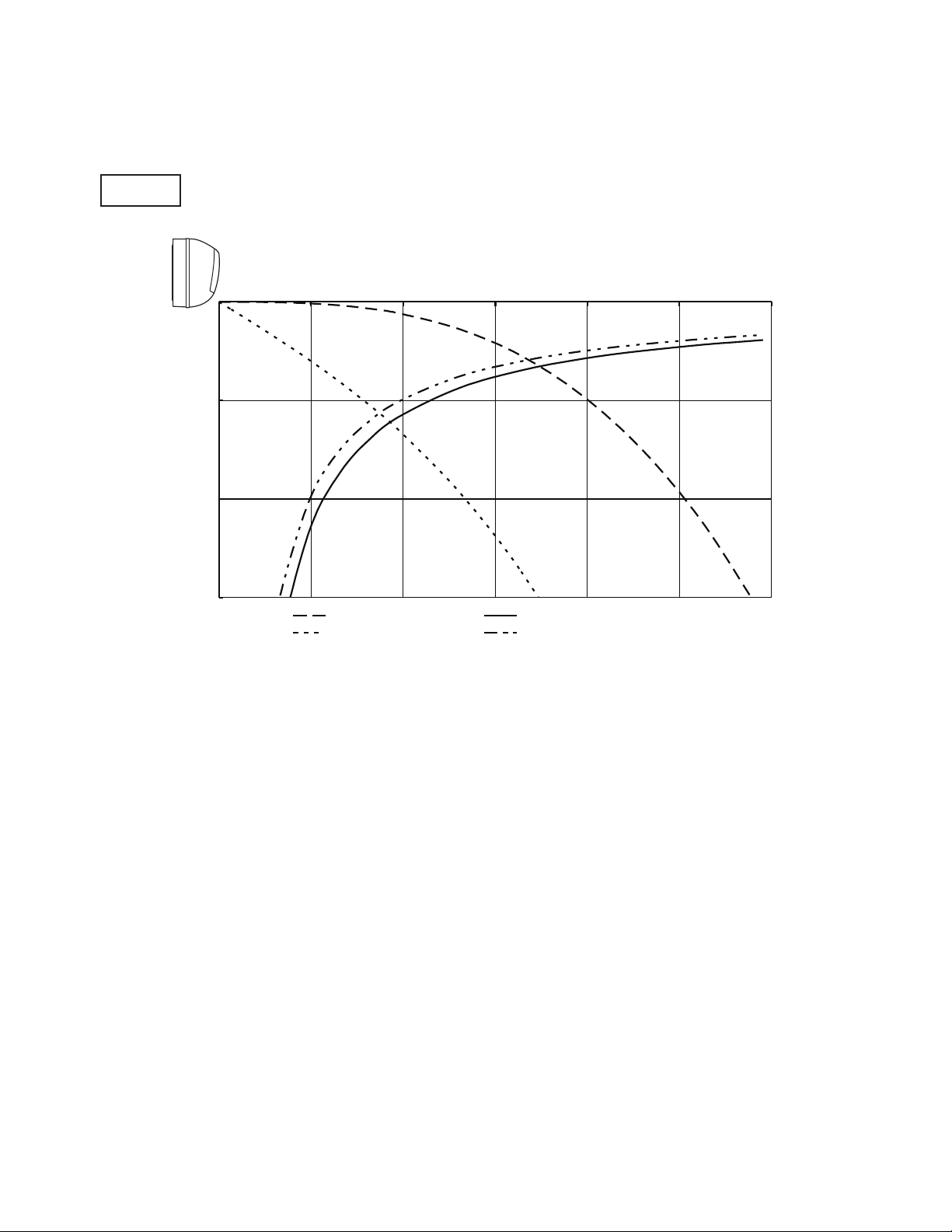
27

Indoor Unit CS-MKS12NKU
0
5
10
15
0 5 10 15 20 25 30
Cooling
Room air temp. : 80°F (26.7°C)
Fan speed : High
Axis air velocity (ft./sec.)
Vertical distance (ft.)
Horizontal distance (ft.)
: Flap angle 0° , : Axis air velocity 0
: Flap angle 30° , : Axis air velocity 30
°
°
28
Indoor Unit CS-MKS18NKU
0
5
10
15
0 5 10 15 20 25 30
Cooling
Room air temp. : 80°F (26.7°C)
Fan speed : High
Axis air velocity (ft./sec.)
Vertical distance (ft.)
Horizontal distance (ft.)
: Flap angle 0° , : Axis air velocity 0
: Flap angle 30° , : Axis air velocity 30
°
°
29

Indoor Unit CS-MKS24NKU
0
5
10
15
0 5 10 15 20 25 30
Cooling
Room air temp. : 80°F (26.7°C)
Fan speed : High
Axis air velocity (ft./sec.)
Vertical distance (ft.)
Horizontal distance (ft.)
: Flap angle 0° , : Axis air velocity 0
: Flap angle 30° , : Axis air velocity 30
°
°
30
 Loading...