

Panasonic CS-KE18NB4UW, CS-MKE12NB4U, CS-MKE9NB4U, CU-4KE31NBU, CU-4KE24NBU User Manual
...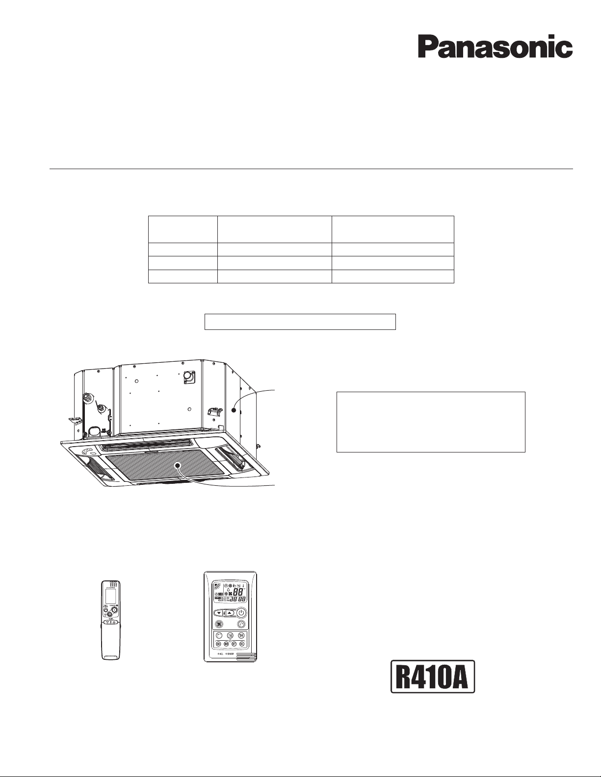
TECHNICAL & SERVICE MANUAL
INDOOR UNIT :
CS-MKE9NB4U & CZ-18BT1U
CS-MKE12NB4U & CZ-18BT1U
CS-KE18NB4UW & CZ-18BT1U
DC INVERTER MULTI-SYSTEM AIR CONDITIONER
Capacity
9,000BTU / h
11,900BTU / h
17,500BTU / h
Indoor Model No.
Body (Panel)
CS-MKE9NB4U (CZ-18BT1U)
CS-MKE12NB4U (CZ-18BT1U)
CS-KE18NB4UW (CZ-18BT1U)
Semi-Concealed Type Indoor Unit
Product Code No.
Body (Panel)
1 852 361 10 (1 852 361 15)
1 852 361 11 (1 852 361 15)
1 852 361 07 (1 852 361 15)
Body
Panel
CS-MKE9NB4U (Body) & CZ-18BT1U (Panel)
CS-MKE12NB4U (Body) & CZ-18BT1U (Panel)
CS-KE18NB4UW (Body) & CZ-18BT1U (Panel)
< Applicable Multi-Outdoor Units >
CU-3KE19NBU (3-room multi unit)
CU-4KE24NBU (4-room multi unit)
CU-4KE31NBU (4-room multi unit)
Remote Controller
Wired Remote Controller
(Option)
REFERENCE NO. SM700882

SAFETY PRECAUTIONS
• Before doing repair work, please read the " SAFETY PRECAUTIONS" carefully and fully understand them.
• The precautionary items here are divided into " Warning" and " Caution" items.
Items in particular which may cause death or serious injury to the service personnel if the work is not performed correctly,
are included in the " Warning" table.
However, even precautionary items identified as " Caution" also have the potential for serious consequences
if not performed correctly.
Important safety precautions are described for all items in both categories. Be sure to carefully follow all of them.
• Symbol Indication
: This symbol indicates items to which we need to pay attention.
In this triangle, a definite precautionary item is described.
: This symbol indicates the item to be prohibited.
In or close to this circle, a prohibited item is described.
: This symbol indicates the items requiring special attention or instruction.
In or close to this circle, a prohibited item is described.
• After doing repair work, perform a test run to confirm that there are no abnormalities.
At the same time, explain the precautions in use to the user.
Warning
Before performing an overhaul, disconnect the power plug or power cable from the unit.
Performing the work with the power supplied to the unit, may cause an electric shock.
When repair work or circuit inspection that requires power supply for the air conditioner, is to be performed,
do not touch the charging section.
Doing so may cause an electric shock.
Prohibit
For the step-up capacitor attached to the electric section, perform the repair work after sufficiently discharging it.
Insufficient capacitor discharge may cause an electric shock.
Do not perform repair work on the electric sections with wet hands.
Doing so may cause an electric shock.
Do not start or stop the air conditioner by means of connecting or disconnecting the power plug.
Doing so may cause an electric shock or fire.
When conducting repair work only use components included in the parts list for the corresponding unit and perform
the work with the appropriate tools.
Incorrect or poor repair work may cause an electric shock or fire.
Never modify the unit.
Doing so may cause an electric shock or fire.
Perform all electric work according to local applicable regulations related to electrical equipment or interior wiring
regulation and make sure to use the exclusive circuit.
Insufficient capacity to the electric circuit or defective arrangement results may cause an electric shock or fire.
Make sure to replace any power cable or lead wire showing any signs of scratch or deterioration.
Failure to do so may cause an electric shock, overheating or fire.
Make sure that there is no dust on or slack in the power plug and insert fully into the socket.
Dust or incomplete connections may cause an electric shock or fire.
Do not damage or process the power cord, as it may cause an electric shock or fire.
Prohibit
Prohibit
Prohibit
Prohibit
For the wiring between the indoor unit and outdoor unit, securely fix the specified cable onto the terminal plate.
Poorly fixed wiring may cause a heat or fire.
After connecting the wiring between the indoor unit and outdoor unit, attach the terminal cover securely.
Incomplete attachment of the terminal cover may cause overheating or fire.
2
Warning
If refrigerant gas blows off during the work, do not touch the refrigerant gas as it may cause frostbite.
If refrigerant gas leaks during the work, ventilate the room.
If refrigerant gas catches fire, harmful gas may be generated.
Do not mix any gas other than the specified refrigerant gas in the refrigerating cycle.
If air or other contaminants mix with the gas, pressure will become extremely high in the refrigerating cycle,
which may cause a unit breakdown."
When the welded section of the compressor intake or discharge pipe is to be disconnected, perform it in
a well-ventilated place after sufficiently recovering the refrigerant gas.
Any residue gas may jet out refrigerant or refrigerating machine oil, which may cause an injury.
When the work is to be performed in a high place (About 2 meters or more), make sure to wear a safety helmet,
gloves and safety belt. Insufficient safety gear may cause a serious injury in case of a fall.
When the unit is to be relocated, confirm that the new installation location has sufficient strength for the weight of the unit.
Insufficient strength of the installation location and incomplete installation work may cause an injury due to
the unit falling.
When the remote controller batteries are replaced, dispose of the old batteries out of the reach of children.
If a child swallows a battery, make sure that the child gets immediate medical attention.
Caution
Prohibit
Prohibit
Do not wash the air conditioner with water, as this may cause an electric shock or fire.
For the repair work in places with high humidity or moisture, make sure to ground the unit.
Failure to do so may cause an electric shock.
Confirm that the component attachment position, wiring condition, soldering condition and connector connection
are normal.
If not, it may cause overheating or fire.
Confirm that the temperature around the compressor is not too high, and then perform the repair work.
Failure to do so may cause a burn.
Perform welding work in a place with good ventilation.
If the work is performed in a poorly ventilated area, it might cause a lack of oxygen.
If the installation plate or attachment frame has deteriorated due to corrosion, etc., replace it.
Failure to do so may cause an injury due to the unit falling.
When the cleaning is to be performed, make sure to turn off the power and pull out the plug.
Touching the fan that is rotating at high speed may result in an injury.
When the indoor unit is to be removed, do not place it on an incline.
Doing so may cause wet furniture because water left inside may trickle down.
Do not hold the sharp end of the unit or the aluminum fins, as it may cause an injury to your hand or finger.
Prohibit
Prohibit
Prohibit
After repairs, make sure to measure the insulation resistance and confirm that the value is 1 Mohm or more.
Any insulation error may cause an electric shock.
After repairs, make sure to check the drainage of the indoor unit.
Inappropriate drainage may cause wet furniture and floors due to water leakage.
3

TABLE OF CONTENTS
Page
SAFETY PRECAUTIONS
TABLE OF CONTENTS
APPLICABLE MULTI-OUTDOOR UNITS
1. OPERATING RANGE
2. SPECIFICATIONS
2-1. Unit Specifications
2-2. Major Component Specifications
2-3. Other Component Specifications
3. DIMENSIONAL DATA
4. REFRIGERANT FLOW DIAGRAM
4-1. Refrigerant Flow Diagram
5. ELECTRICAL DATA
5-1. Electric Wiring Diagrams
.............................................................................................................
....................................................................................................................
...................................................................................................................
.............................................................................................................
....................................................................................................................
..................................................................................................
....................................................................................................
....................................................................................
.......................................................................................
.......................................................................................
2
4
6
7
8
14
17
18
19
20
6. MAINTENANCE
6-1. Disassembly Procedure
7. FUNCTIONS
7-1. Operation Functions
7-2. Protective Functions
8. TROUBLESHOOTING (BEFORE CALLING FOR SERVICE)
8-1. Precautions before Performing Inspection or Repair
8-2. Method of Self-Diagnostics
8-3. Checking the Indoor and Outdoor Units
8-4. Trouble Diagnosis of Fan Motor
8-5. Noise Malfunction and Electromagnetic Interference
APPENDIX A Operating Instructions
(CS-MKE9NB4U & CZ-18BT1U, CS-MKE12NB4U & CZ-18BT1U)
APPENDIX B Operating Instructions
(CS-KE18NB4UW & CZ-18BT1U)
APPENDIX C INSTALLATION INSTRUCTIONS
CS-MKE9NB4U & CZ-18BT1U, CS-MKE12NB4U & CZ-18BT1U,
CS-KE18NB4UW & CZ-18BT1U
()
.....................................................................................................
...........................................................................................................
...........................................................................................................
..........................................................
.................................................................................................
..............................................................................
..........................................................................................
..........................................................
............................................................................................
............................................................................................
.............................................................................
21
28
30
31
31
33
37
38
A-1
A-2
A-3
4

Page
APPENDIX D Operating Instructions
...........................................................................................
(CZ-RD515U)
APPENDIX E INSTALLATION INSTRUCTIONS
(CZ-RD515U)
............................................................................
A-4
A-5
5
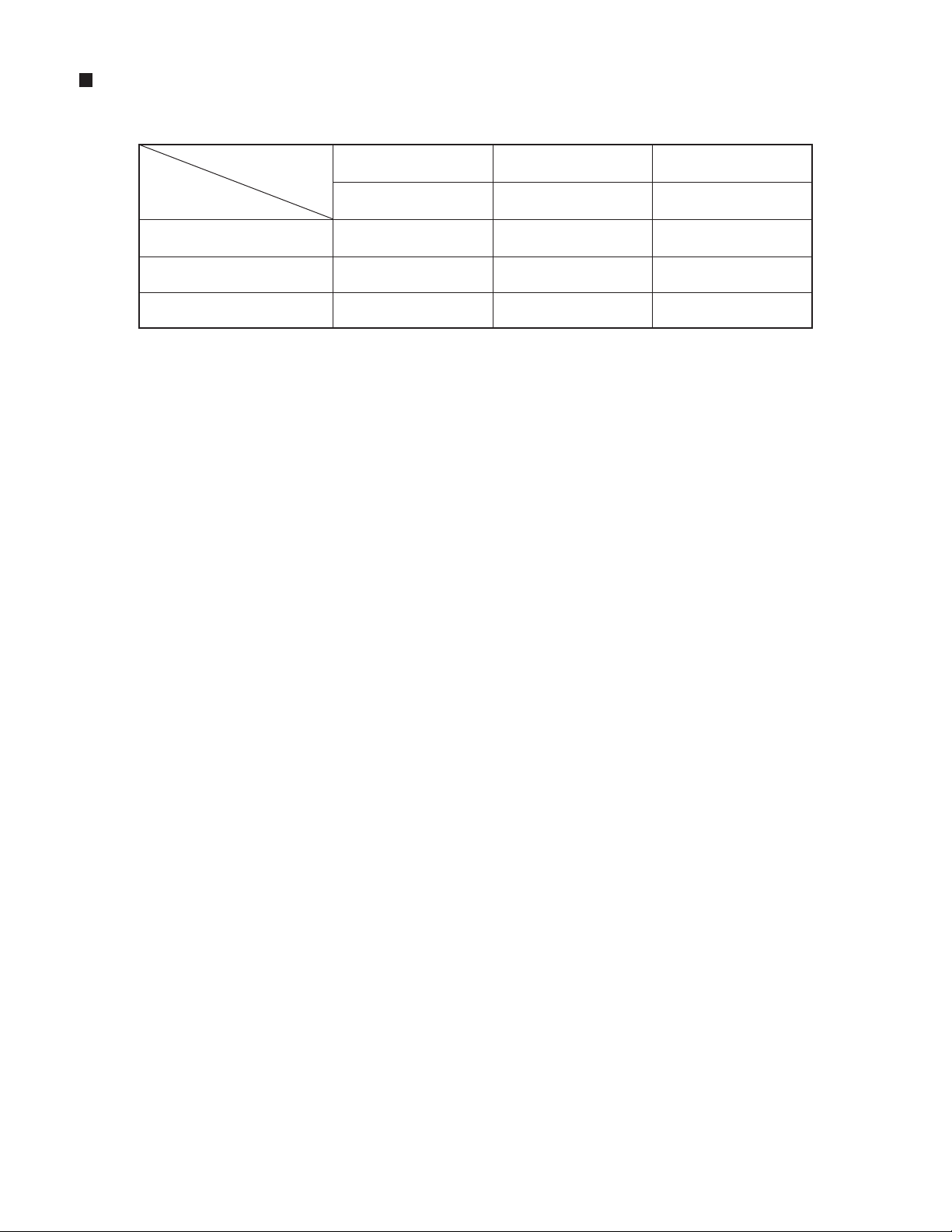
APPLICABLE MULTI-OUTDOOR UNITS
Multi-Outdoor Unit
Indoor Unit
CS-MKE9NB4U & CZ-18BT1U
CS-MKE12NB4U & CZ-18BT1U
CS-KE18NB4UW & CZ-18BT1U
3-Room
CU-3KE19NBU
YES
YES
YES
4-Room
CU-4KE24NBU
YES
YES
YES
4-Room
CU-4KE31NBU
YES
YES
YES
6

1. OPERATING RANGE
Temperature Indoor Air Intake Temp. Outdoor Air Intake Temp.
Cooling
Heating
Maximum
Minimum
Maximum
Minimum
95 °F DB / 71 °F WB
67 °F DB / 57 °F WB
80 °F DB / 67 °F WB
– DB / – WB
115 °F DB
14 °F DB
75 °F DB / 65 °F WB
– DB / 0 °F WB
7

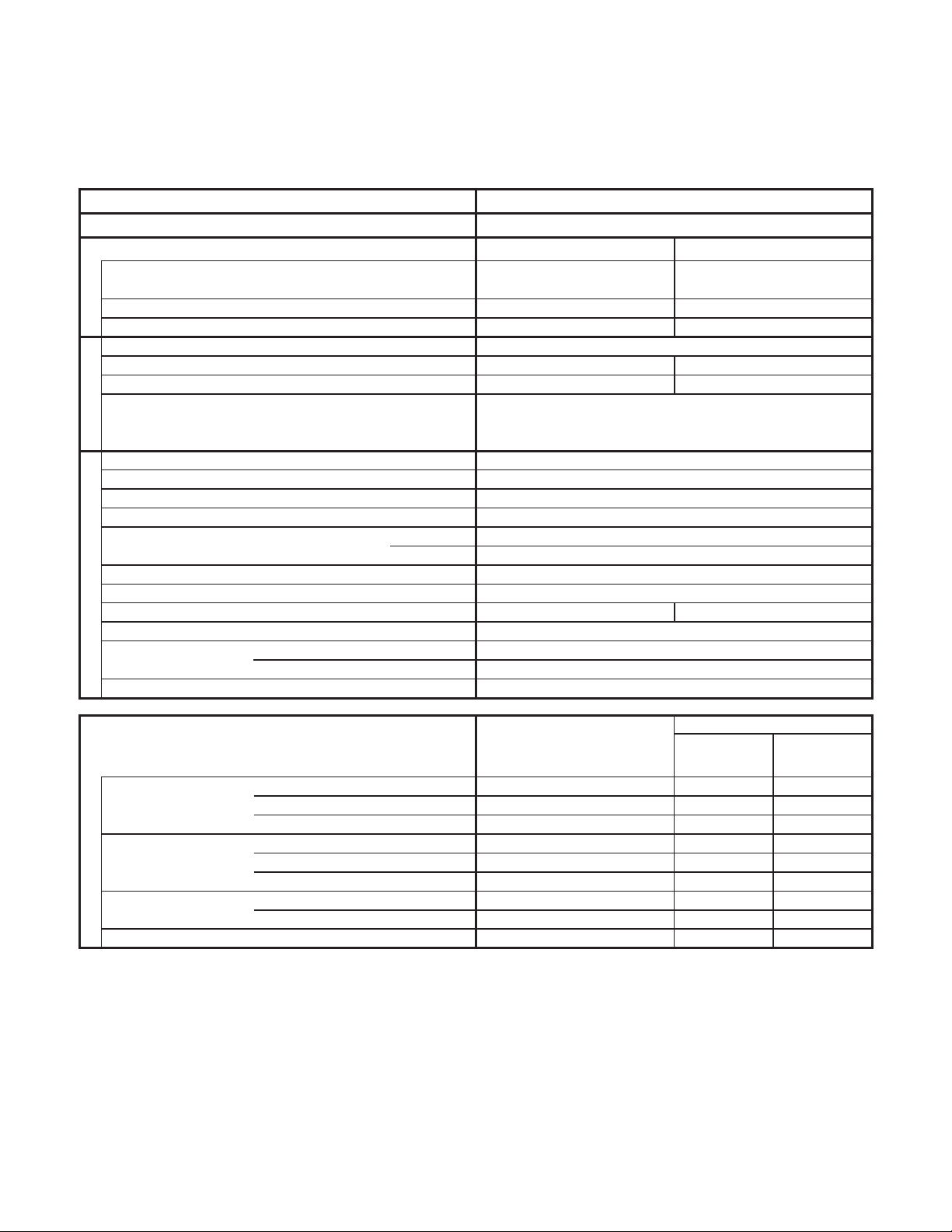
2. SPECIFICATIONS
2-1. Unit Specifications
2-1-1.
Type
Voltage Rating
Performance
Electrical Rating
Features
Indoor Unit CS-MKE9NB4U & CZ-18BT1U
Semi-Concealed Type Indoor Unit
230V Single-Phase 60Hz
Cooling
Total Capacity
Air Circulation (Hi/Me/Lo) ft3/min (m3/h)
Moisture Removal (High) Pints/h
Available Voltage Range
Running Amperes
--
Controls / Temperature Control
Control Unit
Timer
Airflow Direction (Indoor) Horizontal
Air Filter
Refrigerant
Operation Sound
Refrigerant Tubing Connections
Refrigerant inch (mm)
Tube Diameter inch (mm)
Wired Remote Controller (Option) CZ-RD515U
Narrow tube
Wide tube
BTU/h
kW
WPower Input
IndoorFan Speeds
Vertical
dB-AIndoor : Hi/Me/Lo
9,000
2.65
221 (376) / 206 (350) / 194 (330)
3.4
V
A
0.1
16
Microprocessor / I.C. Thermister
Wireless Remote Control Unit
24-Hour ON or OFF Timer, 1-Hour OFF Timer
Auto and 3 steps
Washable, Anti-Mold
33 / 32 / 31 34 / 33 / 32
Flare Type
<230V>
Heating
12,300
3.6
247 (420) / 235 (399) / 224 (381)
-
187 to 253
0.12
18
-
Auto
R410A
1/4 (6.35)
3/8 (9.52)
Dimensions & Weight (Indoor Unit)
Unit Dimensions Height
Width
Depth
Package Dimensions Height
Width
Depth 28-1/8 (714)
Weight Ib. (kg)
Shipping Volume
Remarks: Rating conditions are:
Cooling: Indoor air temperature 80 °F DB / 67 °F WB
Outdoor air temperature 95 °F DB / 75 °F WB
Net
Shipping
Indoor Unit
(CS-MKE9NB4U & CZ-18BT1U)
inch (mm) (313)12-5/16
inch (mm) 22-5/8 (575)
inch (mm)
inch (mm) -
inch (mm) 24-13/16 (630)
inch (mm)
Ib. (kg)
cu.ft (m
3
)
Heating: Indoor air temperature 70 °F DB
(625)24-19/32
(625)24-19/32
-
(18.7)41.3
-
-
DATA SUBJECT TO CHANGE WITHOUT NOTICE.
Outdoor air temperature 47 °F DB / 43 °F WB
(CS-MKE9NB4U)
11-5/32 (283)
11-13/32 (290)
Individual Unit
Body
22-5/8 (575)
35.3 (16)
41.9 (19)
4.59 (0.13)
Panel
(CZ-18BT1U)
1-9/16 (40)
24-19/32 (625)
24-19/32 (625)
4-1/8 (105)
26-3/16 (665)
26-11/16 (678)
6.0 (2.7)
7.7 (3.5)
1.65 (0.04)
8

Indoor Unit CS-MKE9NB4U & CZ-18BT1U
Type
Voltage Rating
Total Capacity
BTU/h
kW
Air Circulation (Hi/Me/Lo) ft3/min (m3/h)
Performance
Moisture Removal (High) Pints/h
Available Voltage Range
Running Amperes
221 (376) / 206 (350) / 194 (330)
V
A
WPower Input
--
Electrical Rating
Controls / Temperature Control
Control Unit
Timer
IndoorFan Speeds
Airflow Direction (Indoor) Horizontal
Vertical
Air Filter
Refrigerant
Features
Operation Sound
dB-AIndoor : Hi/Me/Lo
Refrigerant Tubing Connections
Refrigerant inch (mm)
Tube Diameter inch (mm)
Narrow tube
Wide tube
Wired Remote Controller (Option) CZ-RD515U
Semi-Concealed Type Indoor Unit
208V Single-Phase 60Hz
Cooling
9,000
2.65
3.4
0.11
15
Microprocessor / I.C. Thermister
Wireless Remote Control Unit
24-Hour ON or OFF Timer, 1-Hour OFF Timer
Auto and 3 steps
Washable, Anti-Mold
33 / 32 / 31 34 / 33 / 32
<208V>
Heating
12,300
3.6
247 (420) / 235 (399) / 224 (381)
-
187 to 253
0.13
17
-
Auto
R410A
Flare Type
1/4 (6.35)
3/8 (9.52)
Dimensions & Weight (Indoor Unit)
Unit Dimensions Height
Width
Depth
Package Dimensions Height
Width
Depth 28-1/8 (714)
Weight Ib. (kg)
Shipping Volume
Net
Shipping
Remarks: Rating conditions are:
Cooling: Indoor air temperature 80 °F DB / 67 °F WB
Outdoor air temperature 95 °F DB / 75 °F WB
Indoor Unit
(CS-MKE9NB4U & CZ-18BT1U)
inch (mm) (313)12-5/16
inch (mm) 22-5/8 (575)
inch (mm)
inch (mm) -
inch (mm) 24-13/16 (630)
inch (mm)
Ib. (kg)
cu.ft (m
3
)
(625)24-19/32
(625)24-19/32
-
(18.7)41.3
-
-
(CS-MKE9NB4U)
11-5/32 (283)
11-13/32 (290)
Individual Unit
Body
22-5/8 (575)
35.3 (16)
41.9 (19)
4.59 (0.13)
DATA SUBJECT TO CHANGE WITHOUT NOTICE.
Heating: Indoor air temperature 70 °F DB
Outdoor air temperature 47 °F DB / 43 °F WB
Panel
(CZ-18BT1U)
1-9/16 (40)
24-19/32 (625)
24-19/32 (625)
4-1/8 (105)
26-3/16 (665)
26-11/16 (678)
6.0 (2.7)
7.7 (3.5)
1.65 (0.04)
9

2-1-2. Indoor Unit CS-MKE12NB4U & CZ-18BT1U
Type
Voltage Rating
Total Capacity
BTU/h
kW
Air Circulation (Hi/Me/Lo) ft3/min (m3/h)
Performance
Moisture Removal (High) Pints/h
Available Voltage Range
Running Amperes
235 (399) / 206 (350) / 194 (330)
V
A
WPower Input
--
Electrical Rating
Controls / Temperature Control
Control Unit
Timer
IndoorFan Speeds
Airflow Direction (Indoor) Horizontal
Vertical
Air Filter
Refrigerant
Features
Operation Sound
dB-AIndoor : Hi/Me/Lo
Refrigerant Tubing Connections
Refrigerant inch (mm)
Tube Diameter inch (mm)
Narrow tube
Wide tube
Wired Remote Controller (Option) CZ-RD515U
Semi-Concealed Type Indoor Unit
230V Single-Phase 60Hz
Cooling
11,900
3.5
4.26
0.11
17
Microprocessor / I.C. Thermister
Wireless Remote Control Unit
24-Hour ON or OFF Timer, 1-Hour OFF Timer
Auto and 3 steps
Washable, Anti-Mold
34 / 32 / 31 35 / 34 / 32
<230V>
Heating
13,600
4.0
268 (455) / 247 (420) / 224 (381)
-
187 to 253
0.13
19
-
Auto
R410A
Flare Type
1/4 (6.35)
3/8 (9.52)
Dimensions & Weight (Indoor Unit)
Unit Dimensions Height
Width
Depth
Package Dimensions Height
Width
Depth 28-1/8 (714)
Weight Ib. (kg)
Shipping Volume
Net
Shipping
Remarks: Rating conditions are:
Cooling: Indoor air temperature 80 °F DB / 67 °F WB
Outdoor air temperature 95 °F DB / 75 °F WB
Indoor Unit
(CS-MKE12NB4U & CZ-18BT1U)
inch (mm) (313)12-5/16
inch (mm) 22-5/8 (575)
inch (mm)
inch (mm) -
inch (mm) 24-13/16 (630)
inch (mm)
Ib. (kg)
cu.ft (m
3
)
(625)24-19/32
(625)24-19/32
-
(18.7)41.3
-
-
(CS-MKE12NB4U)
11-5/32 (283)
11-13/32 (290)
Individual Unit
Body
22-5/8 (575)
35.3 (16)
41.9 (19)
4.59 (0.13)
DATA SUBJECT TO CHANGE WITHOUT NOTICE.
Heating: Indoor air temperature 70 °F DB
Outdoor air temperature 47 °F DB / 43 °F WB
Panel
(CZ-18BT1U)
1-9/16 (40)
24-19/32 (625)
24-19/32 (625)
4-1/8 (105)
26-3/16 (665)
26-11/16 (678)
6.0 (2.7)
7.7 (3.5)
1.65 (0.04)
10
Indoor Unit CS-MKE12NB4U & CZ-18BT1U
Type
Voltage Rating
Total Capacity
BTU/h
kW
Air Circulation (Hi/Me/Lo) ft3/min (m3/h)
Performance
Moisture Removal (High) Pints/h
Available Voltage Range
Running Amperes
235 (399) / 206 (350) / 194 (330)
V
A
WPower Input
--
Electrical Rating
Controls / Temperature Control
Control Unit
Timer
IndoorFan Speeds
Airflow Direction (Indoor) Horizontal
Vertical
Air Filter
Refrigerant
Features
Operation Sound
dB-AIndoor : Hi/Me/Lo
Refrigerant Tubing Connections
Refrigerant inch (mm)
Tube Diameter inch (mm)
Narrow tube
Wide tube
Wired Remote Controller (Option) CZ-RD515U
Semi-Concealed Type Indoor Unit
208V Single-Phase 60Hz
Cooling
11,900
3.5
4.26
0.12
16
Microprocessor / I.C. Thermister
Wireless Remote Control Unit
24-Hour ON or OFF Timer, 1-Hour OFF Timer
Auto and 3 steps
Washable, Anti-Mold
34 / 32 / 31 35 / 34 / 32
<208V>
Heating
13,600
4.0
268 (455) / 247 (420) / 224 (381)
-
187 to 253
0.14
18
-
Auto
R410A
Flare Type
1/4 (6.35)
3/8 (9.52)
Dimensions & Weight (Indoor Unit)
Unit Dimensions Height
Width
Depth
Package Dimensions Height
Width
Depth 28-1/8 (714)
Weight Ib. (kg)
Shipping Volume
Net
Shipping
Remarks: Rating conditions are:
Cooling: Indoor air temperature 80 °F DB / 67 °F WB
Outdoor air temperature 95 °F DB / 75 °F WB
Indoor Unit
(CS-MKE12NB4U & CZ-18BT1U)
inch (mm) (313)12-5/16
inch (mm) 22-5/8 (575)
inch (mm)
inch (mm) -
inch (mm) 24-13/16 (630)
inch (mm)
Ib. (kg)
cu.ft (m
3
)
(625)24-19/32
(625)24-19/32
-
(18.7)41.3
-
-
(CS-MKE12NB4U)
11-5/32 (283)
11-13/32 (290)
Individual Unit
Body
22-5/8 (575)
35.3 (16)
41.9 (19)
4.59 (0.13)
DATA SUBJECT TO CHANGE WITHOUT NOTICE.
Heating: Indoor air temperature 70 °F DB
Outdoor air temperature 47 °F DB / 43 °F WB
Panel
(CZ-18BT1U)
1-9/16 (40)
24-19/32 (625)
24-19/32 (625)
4-1/8 (105)
26-3/16 (665)
26-11/16 (678)
6.0 (2.7)
7.7 (3.5)
1.65 (0.04)
11

2-1-3. Indoor Unit CS-KE18NB4UW & CZ-18BT1U
Type
Voltage Rating
Total Capacity
BTU/h
kW
Air Circulation (Hi/Me/Lo) ft3/min (m3/h)
Performance
Moisture Removal (High) Pints/h
Available Voltage Range
Running Amperes
341 (579) / 294 (500) / 253 (430)
V
A
WPower Input
--
Electrical Rating
Controls / Temperature Control
Control Unit
Timer
IndoorFan Speeds
Airflow Direction (Indoor) Horizontal
Vertical
Air Filter
Refrigerant
Features
Operation Sound
dB-AIndoor : Hi/Me/Lo
Refrigerant Tubing Connections
Refrigerant inch (mm)
Tube Diameter inch (mm)
Narrow tube
Wide tube
Wired Remote Controller (Option) CZ-RD515U
Semi-Concealed Type Indoor Unit
230V Single-Phase 60Hz
Cooling
17,500
5.15
4.89
0.15
22
Microprocessor / I.C. Thermister
Wireless Remote Control Unit
24-Hour ON or OFF Timer, 1-Hour OFF Timer
Auto and 3 steps
Washable, Anti-Mold
44 / 40 / 36 44 / 40 / 36
<230V>
Heating
20,400
6.0
383 (651) / 324 (551) / 265 (450)
-
187 to 253
0.19
27
-
Auto
R410A
Flare Type
1/4 (6.35)
1/2 (12.7)
Dimensions & Weight (Indoor Unit)
Unit Dimensions Height
Width
Depth
Package Dimensions Height
Width
Depth 28-1/8 (714)
Weight Ib. (kg)
Shipping Volume
Net
Shipping
Remarks: Rating conditions are:
Cooling: Indoor air temperature 80 °F DB / 67 °F WB
Outdoor air temperature 95 °F DB / 75 °F WB
Indoor Unit
(CS-KE18NB4UW & CZ-18BT1U)
inch (mm) (313)12-5/16
inch (mm) 22-5/8 (575)
inch (mm)
inch (mm) -
inch (mm) 24-13/16 (630)
inch (mm)
Ib. (kg)
cu.ft (m
3
)
(625)24-19/32
(625)24-19/32
-
(18.7)41.3
-
-
(CS-KE18NB4UW)
11-5/32 (283)
11-13/32 (290)
Individual Unit
Body
22-5/8 (575)
35.3 (16)
41.9 (19)
4.59 (0.13)
DATA SUBJECT TO CHANGE WITHOUT NOTICE.
Heating: Indoor air temperature 70 °F DB
Outdoor air temperature 47 °F DB / 43 °F WB
Panel
(CZ-18BT1U)
1-9/16 (40)
24-19/32 (625)
24-19/32 (625)
4-1/8 (105)
26-3/16 (665)
26-11/16 (678)
6.0 (2.7)
7.7 (3.5)
1.65 (0.04)
12

Indoor Unit CS-KE18NB4UW & CZ-18BT1U
Type
Voltage Rating
Total Capacity
BTU/h
kW
Air Circulation (Hi/Me/Lo) ft3/min (m3/h)
Performance
Moisture Removal (High) Pints/h
Available Voltage Range
Running Amperes
341 (579) / 294 (500) / 253 (430)
V
A
WPower Input
--
Electrical Rating
Controls / Temperature Control
Control Unit
Timer
IndoorFan Speeds
Airflow Direction (Indoor) Horizontal
Vertical
Air Filter
Refrigerant
Features
Operation Sound
dB-AIndoor : Hi/Me/Lo
Refrigerant Tubing Connections
Refrigerant inch (mm)
Tube Diameter inch (mm)
Narrow tube
Wide tube
Wired Remote Controller (Option) CZ-RD515U
Semi-Concealed Type Indoor Unit
208V Single-Phase 60Hz
Cooling
17,500
5.15
4.89
0.16
22
Microprocessor / I.C. Thermister
Wireless Remote Control Unit
24-Hour ON or OFF Timer, 1-Hour OFF Timer
Auto and 3 steps
Washable, Anti-Mold
44 / 40 / 36 44 / 40 / 36
<208V>
Heating
20,400
6.0
383 (651) / 324 (551) / 265 (450)
-
187 to 253
0.2
27
-
Auto
R410A
Flare Type
1/4 (6.35)
1/2 (12.7)
Dimensions & Weight (Indoor Unit)
Unit Dimensions Height
Width
Depth
Package Dimensions Height
Width
Depth 28-1/8 (714)
Weight Ib. (kg)
Shipping Volume
Net
Shipping
Remarks: Rating conditions are:
Cooling: Indoor air temperature 80 °F DB / 67 °F WB
Outdoor air temperature 95 °F DB / 75 °F WB
Indoor Unit
(CS-KE18NB4UW & CZ-18BT1U)
inch (mm) (313)12-5/16
inch (mm) 22-5/8 (575)
inch (mm)
inch (mm) -
inch (mm) 24-13/16 (630)
inch (mm)
Ib. (kg)
cu.ft (m
3
)
(625)24-19/32
(625)24-19/32
-
(18.7)41.3
-
-
(CS-KE18NB4UW)
11-5/32 (283)
11-13/32 (290)
Individual Unit
Body
22-5/8 (575)
35.3 (16)
41.9 (19)
4.59 (0.13)
DATA SUBJECT TO CHANGE WITHOUT NOTICE.
Heating: Indoor air temperature 70 °F DB
Outdoor air temperature 47 °F DB / 43 °F WB
Panel
(CZ-18BT1U)
1-9/16 (40)
24-19/32 (625)
24-19/32 (625)
4-1/8 (105)
26-3/16 (665)
26-11/16 (678)
6.0 (2.7)
7.7 (3.5)
1.65 (0.04)
13
2-2. Major Component Specifications
2-2-1. Indoor Unit
Indoor Unit (Body) CS-MKE9NB4U
Control PCB
Part No.
Controls
Control Circuit Fuse
Fan
Type
Q'ty ... Dia. and Length
Fan Motor
Type
Model ... Q'ty
No. of Poles
Rough Measure RPM (Cool / Heat)
Rating Voltage / Nominal Output
Coil Resistance
(Ambient Temp. 68 °F (20 °C))
Safety Device
Type
Over- Current Protection
Over- Heat Protection
Run Capacitor Micro F
inch (mm)
Ohm
VAC
CB-CS-MKE9NB4U
Microprocessor
250V 3A
Turbo
1 ... D12-5/8 / L5-3/4 (D322/L147)
DC Motor
SIC-62FW-D866-2 ... 1
8
440 / 490
DC280V / 23W
-
Internal Controller
Yes
Yes
-
-
Drain Pump
Model ... Q'ty
Rating Voltage, Hz
(Ambient Temp. 68 °F (20 °C))
Safety Device
Heat Exchanger Coil
Coil
Rows
Fins per inch
Input
Type
Open
W
Ohm
°F (°C)
2
(m2)
ft
DATA SUBJECT TO CHANGE WITHOUT NOTICE.
PLD-12230ST-1 ... 1
AC208 to 240V, 60Hz
Aluminum Plate Fin / Copper Tube
Indoor Unit (Panel) CZ-18BT1U
Flap Motor
Type Stepping Motor
Model ... Q'ty
Rating
Coil Resistance Ohm
(Ambient Temp. 77 °F (25 °C))
Each Pair of Terminal : 380 +/- 7%
DATA SUBJECT TO CHANGE WITHOUT NOTICE.
MP24ZN-12V ... 2
10.8
333 +/- 10%Coil Resistance
Thermal Fuse
293 (145)
2
18.1
2.94 (0.273) Face Area
DC 12V
14

Indoor Unit (Body) CS-MKE12NB4U
Control PCB
Part No.
Controls
Control Circuit Fuse
Fan
Type
Q'ty ... Dia. and Length
Fan Motor
Type
Model ... Q'ty
No. of Poles
Rough Measure RPM (Cool / Heat)
Coil Resistance
(Ambient Temp. 68 °F (20 °C))
Safety Device
Type
Over- Current Protection
Over- Heat Protection
Run Capacitor Micro F
inch (mm)
Ohm
VAC
CB-CS-MKE12NB4U
Microprocessor
250V 3A
Turbo
1 ... D12-5/8 / L5-3/4 (D322/L147)
DC Motor
SIC-62FW-D866-2 ... 1
8
470 / 520
DC280V / 23WRating Voltage / Nominal Output
-
Thermal Fuse
Yes
Yes
-
-
Drain Pump
Model ... Q'ty
Rating Voltage, Hz
Input
W
PLD-12230ST-1 ... 1
AC208 to 240V, 60Hz
Ohm
(Ambient Temp. 68 °F (20 °C))
Safety Device
Type
Open
°F (°C)
Heat Exchanger Coil
Coil
Aluminum Plate Fin / Copper Tube
Rows
Fins per inch
2
(m2)
ft
DATA SUBJECT TO CHANGE WITHOUT NOTICE.
Indoor Unit (Panel) CZ-18BT1U
Flap Motor
Type Stepping Motor
Model ... Q'ty
Rating
Coil Resistance Ohm
(Ambient Temp. 77 °F (25 °C))
Each Pair of Terminal : 380 +/- 7%
DATA SUBJECT TO CHANGE WITHOUT NOTICE.
MP24ZN-12V ... 2
10.8
333 +/- 10%Coil Resistance
Thermal Fuse
293 (145)
2
18.1
2.94 (0.273) Face Area
DC 12V
15

Indoor Unit (Body) CS-KE18NB4UW
Control PCB
Part No.
Controls
Control Circuit Fuse
Fan
Type
Q'ty ... Dia. and Length
Fan Motor
Type
Model ... Q'ty
No. of Poles
Rough Measure RPM (Cool / Heat)
Coil Resistance
(Ambient Temp. 68 °F (20 °C))
Safety Device
Type
Over- Current Protection
Over- Heat Protection
Run Capacitor Micro F
inch (mm)
Ohm
VAC
CB-CS-KE18NB4U
Microprocessor
250V 3A
Turbo
1 ... D12-5/8 / L5-3/4 (D322/L147)
DC Motor
SIC-62FW-D866-2 ... 1
8
650 / 720
DC340V / 20WRating Voltage / Nominal Output
-
Internal Controller
Yes
Yes
-
-
Drain Pump
Model ... Q'ty
Rating Voltage, Hz
Input
W
PLD-12230ST-1 ... 1
AC208 to 240V, 60Hz
Ohm
(Ambient Temp. 68 °F (20 °C))
Safety Device
Type
Open
°F (°C)
Heat Exchanger Coil
Coil
Aluminum Plate Fin / Copper Tube
Rows
Fins per inch
2
(m2)
ft
DATA SUBJECT TO CHANGE WITHOUT NOTICE.
Indoor Unit (Panel) CZ-18BT1U
Flap Motor
Type Stepping Motor
Model ... Q'ty
Rating
Coil Resistance Ohm
(Ambient Temp. 77 °F (25 °C))
Each Pair of Terminal : 380 +/- 7%
DATA SUBJECT TO CHANGE WITHOUT NOTICE.
MP24ZN-12V ... 2
10.8
333 +/- 10%Coil Resistance
Thermal Fuse
293 (145)
2
18.1
2.94 (0.273) Face Area
DC 12V
16
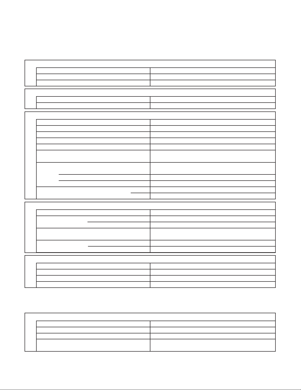
2-3. Other Component Specifications
Indoor Unit CS-MKE9NB4U & CZ-18BT1U
CS-MKE12NB4U & CZ-18BT1U
CS-KE18NB4UW & CZ-18BT1U
• Indoor air temp sensor
(Model:KTEC-35-S98)
10
9
8
7
6
5
Resistance (k ohm)
4
3
2
1
0
50
59 68 77 86 95 104
(10) (15) (20) (25) (30) (35) (40)
Temperature °F (°C)
• Indoor heat exchanger sensor
(Model:PT2M-51H-S3)
200
180
160
140
120
100
Resistance (k ohm)
80
60
40
20
0
32 50 68 86 104 122 140 158 176 194
(0) (10) (20) (30) (40) (50) (60) (70)(80) (90)
Temperature °F (°C)
17
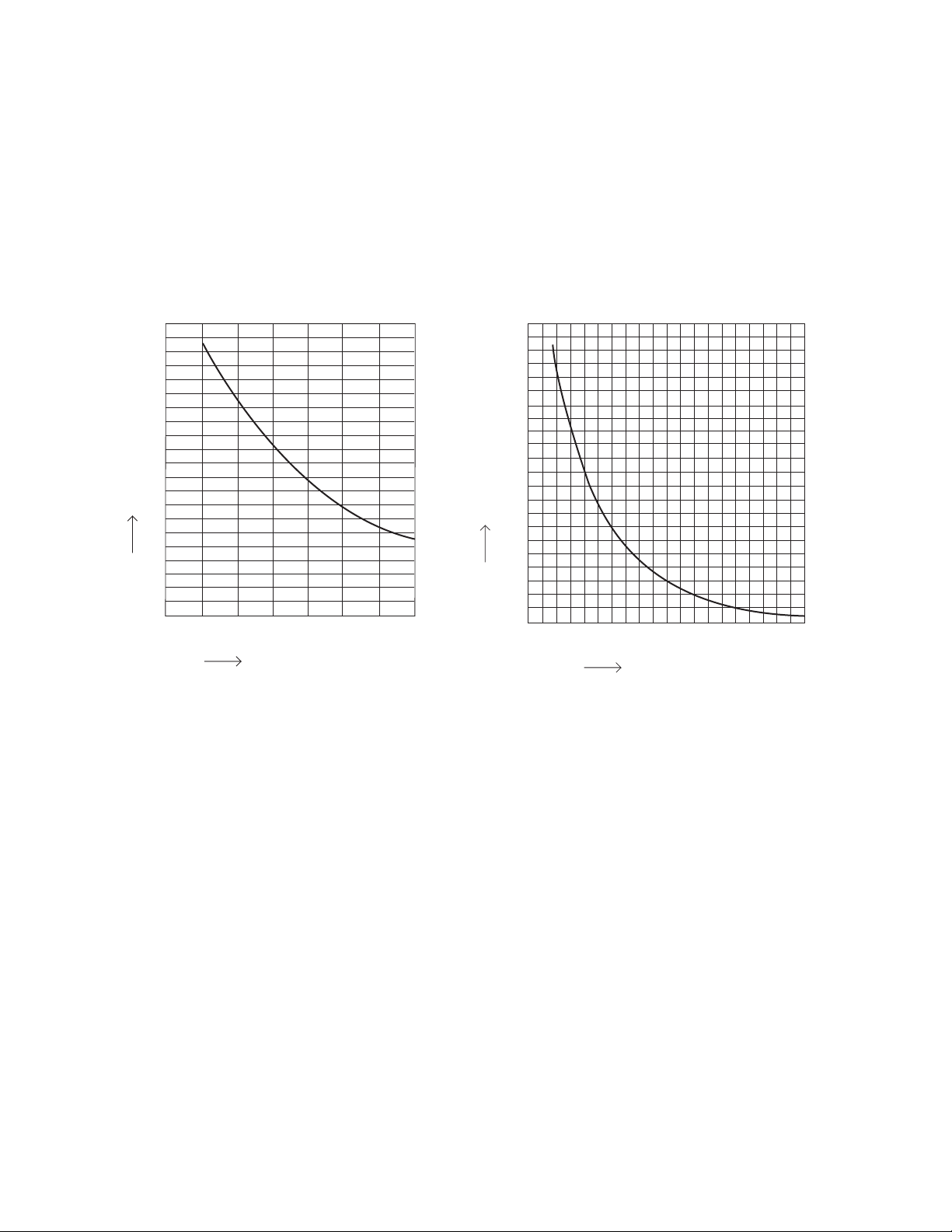
3. DIMENSIONAL DATA
Indoor Unit CS-MKE9NB4U & CZ-18BT1U
CS-MKE12NB4U & CZ-18BT1U
CS-KE18NB4UW & CZ-18BT1U
7-11/16
8
4-29/32
A View
1-3/16
21/32
3-1/8
AA
(534)
23-5/8 (600)
21-1/32
Suspension bolt pitch
Ceiling opening dimensions
Center of
panel
7
(flared)
1/4" (flared)
dia.
dia. 1/2"
23-5/8 (600)
21-1/32 (534)
Ceiling opening dimensions
Suspension bolt pitch
12-7/16
12-7/8
5
22-5/8 (575)
6-5/16 6-11/16
2-3/32
1-25/32
1-3/16 (30)
11-5/32 (283)
8-15/32
3
6
1-25/32
4-19/32
Less than 31/32Less than 31/32
The length of the suspension
2
14-3/32 (358)
24-19/32 (625)
2
25/32
bolts should be selected so that
there is a gap of 1-3/16" or
the ceiling (21/32" or more
below the lower surface of the
main unit), as shown in the
figure at right. If the suspension
bolts is too long, it will contact
the ceiling panel and the unit
cannot be installed.
24-19/32 (625)
13-5/32 (334)
2
1
5-9/16
2-3/4 1-9/32
2
(liquid tube)
Air intake
Discharge outlet
Refrigerant tubing
1
2
3
(gas tube)
22-5/8 (575)
Refrigerant tubing
Drain tube connection port VP20 (outer dia. 1")
Power supply port
Suspension bolt hole (4 - 1/2" x 1-1/8" hole)
Fresh air intake duct connection port (dia. 3-7/8")
4
5
6
7
8
18
2-3/32
3-5/8
7-23/32
1-27/32 1-3/32
Unit : inch (mm)
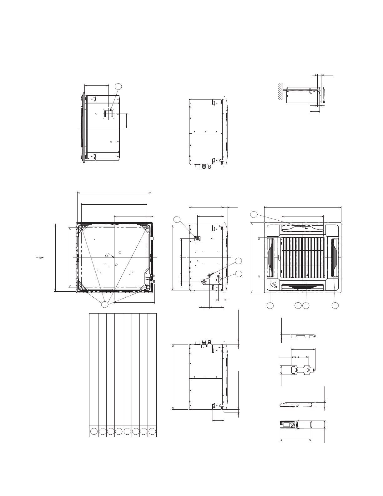
4. REFRIGERANT FLOW DIAGRAM
4-1. Refrigerant Flow Diagram
Indoor Unit CS-MKE9NB4U & CZ-18BT1U
CS-MKE12NB4U & CZ-18BT1U
Indoor unit
O.D. 3/8" (9.52 mm)
Heat exchanger
Strainer
Indoor Unit CS-KE18NB4UW & CZ-18BT1U
Indoor unit
Heat exchanger
Strainer
O.D. 1/4" (6.35 mm)
O.D. 1/2" (12.7 mm)
O.D. 1/4" (6.35 mm)
Cooling cycle
Heating cycle
Cooling cycle
Heating cycle
19
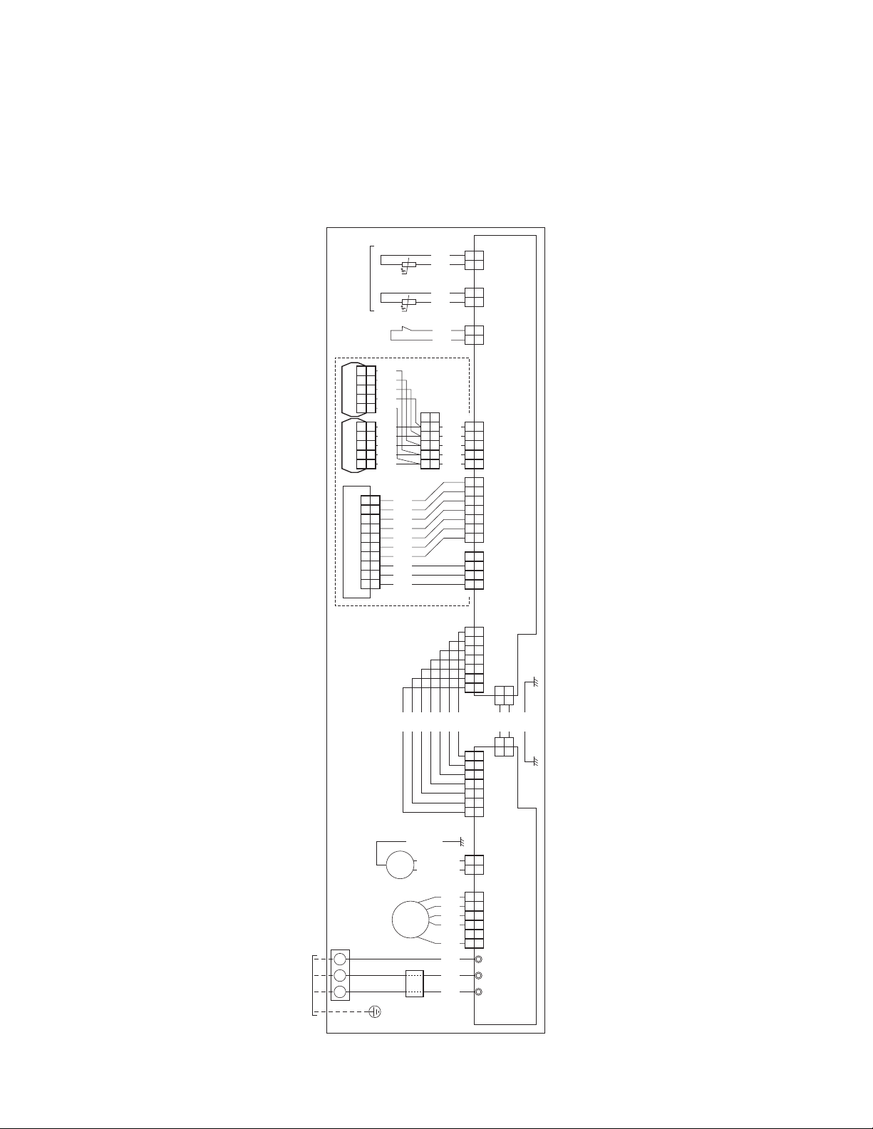
5. ELECTRICAL DATA
5-1. Electric Wiring Diagrams
Indoor Unit CS-MKE9NB4U & CZ-18BT1U
CS-MKE12NB4U & CZ-18BT1U
CS-KE18NB4UW & CZ-18BT1U
FLAP (R)
FLAP (W)
IND LAMP ASSY
COIL-1
BLK
2
2
BLK
1
1
COIL-1
WHT
BRN
BLU
ORG
BLK
2P (RED)
2
2
1
1
ROOM
2P (YEL)
3
3
FS
1
1
3P (RED)
5
5
4
4
3
3
FLAP
2
2
5P (WHT)
1
1
7
7
6
6
5
5
4
4
IND
3
3
7P (WHT)
2
2
1
1
4
4
3
3
2
2
1
1
4P (WHT)
8FA2-5250-46900-2
ROOM
BLK
VLT
BLU
PNK
YEL
ORG
RED
BRN
GRN
BLK
WHT
BLK
BLK
BLK
FLOAT SWITCH
6
6
5
5
4
4
3
3
2
2
1
1
THERMISTOR
ORG
5
5
BLU
4
4
BRN
3
3
WHT
2
2
BLK
1
1
WHT
5
5
BRN
4
4
BLU
3
3
ORG
2
2
BLK
1
1
10
10
9
9
8
8
7
7
6
6
5
5
4
4
3
3
2
2
1
1
TERMINAL BASE
2 3
1
TO OUTDOOR UNIT
BRN
DP
DRAIN PUMP
FAN MOTOR
GND
RED
FM
YEL
ORG
CORE
FERRITE
VLT
BLU
PNK
GRN/YEL
YEL/(RED)
YEL/(RED)
BLU
YEL
WHT
BLK
RED
RED
WHT
BLK
7
7
6
6
5
5
4
4
3
3
2
2
SERIAL
2P (WHT)
1
1
1 1
2 2
RED
GRN
WHT
1 1
2 2
7
7
6
6
5
5
4
4
3
3
2
2
1
1
3
3
1
1
PWM/POW 7P (RED) PWM/POW 7P (RED) RC
DP
SERIAL
2P (WHT)
3P (BLU)
3P (RED)
BOX BOX
CONTROLLER CONTROLLER
DCM
6P (BLU)
6P (WHT)
1 2 3 4 5 6
1 2 3 4 5 6
AC1 AC2 SI
20
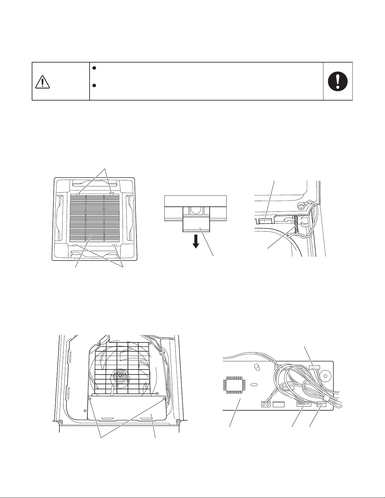
6. MAINTENANCE
6-1. Disassembly Procedure
To avoid electrical shock hazard, be sure to disconnect power before
Warning
6-1-1. Remove the air intake grill.
(1) Slide the 2 latches each to the corresponding arrow direction. (Fig. 1 and Fig. 2)
Open downward the air intake grill located on the latch side.
(2) Undo the air intake grill drop preventive hook. (Fig. 3)
Undo the 2 hinges for the grill and remove the air intake grill.
attempting to disassemble the unit.
When a footstool, etc. is used for disassembling the indoor unit,
be careful not to fall down. If you fall down, you might be injured seriously.
Latch
Hinge
Latch
Air intake grill
Fig.1
Hinge
Fig.2 Fig.3
6-1-2. Disconnect the connectors in the control box.
(1) Remove the 2 screws and remove the control box cover. (Fig. 4)
(2) Disconnect the connectors CN04 (FLAP 5P), CN12 (RC 4P) and CN13 (IND 7P). (Fig. 5)
Control PCboard
Hook
CN13
CN04
CN12
Screw Control box cover
Fig.4 Fig.5
21
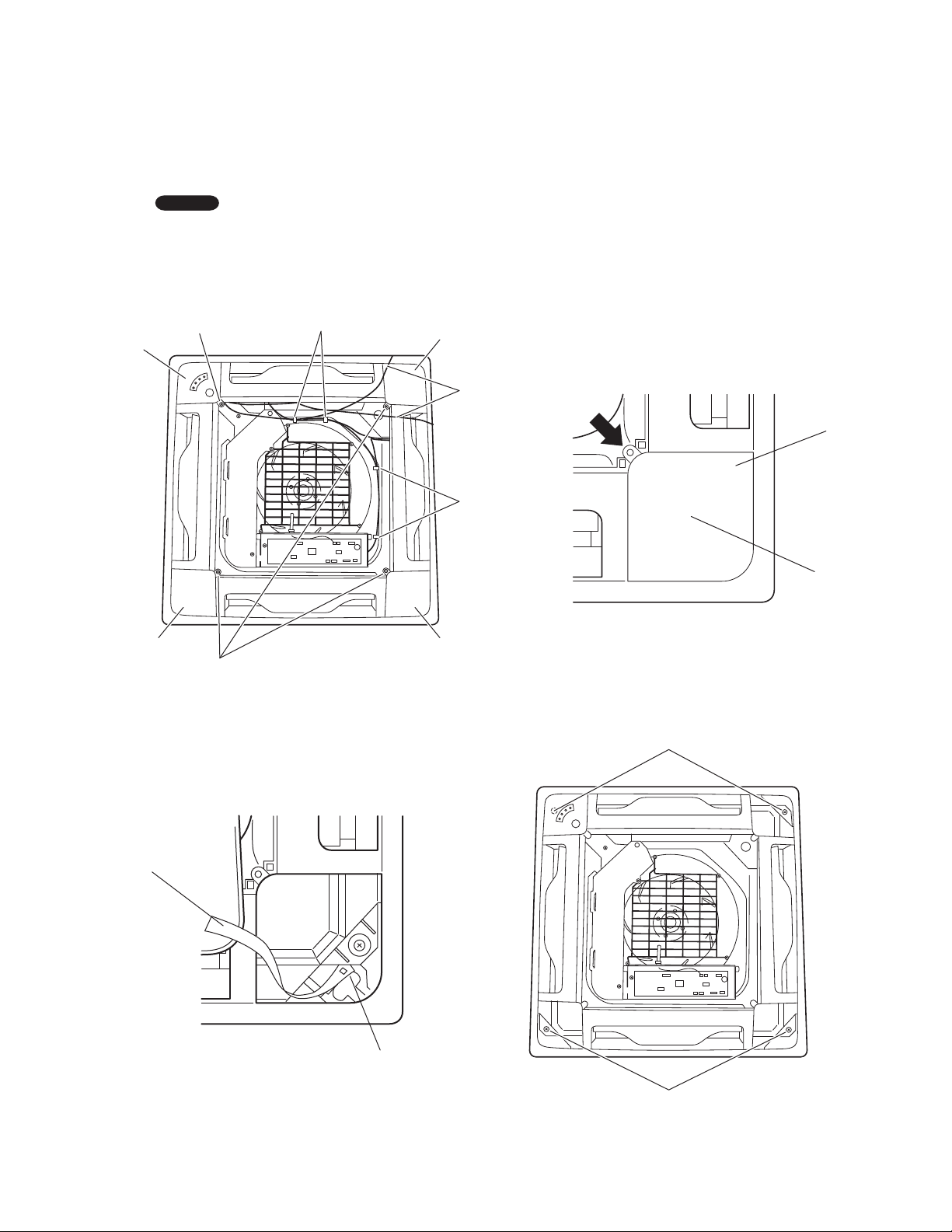
6-1-3. Remove the ceiling panel.
(1) Open the clamp (4 locations) and remove the 2 lead wires from the clamps. (Fig. 6)
(2) Remove the 4 screws fixing the corner cover (at 3 locations) and indicator cover (at 1 location). (Fig. 6)
(3) Press the center 1 of the cover and remove the cover with the section 2 pulled down. (Fig. 7)
(4) Remove the strap (3 locations) from the hook on the ceiling panel. (Fig. 8)
NOTE
(5) Remove the bolt (4 locations) with a washer and remove the ceiling panel. (Fig. 9)
There is no strap on the indicator cover.
Indicator
cover
Screw
Screw
Clamp
Corner cover
Lead wire
Clamp
Corner coverCorner cover
Pull down
section 2.
Fig.6 Fig.7
Bolt
Cover
Center 1
Strap
Remove the strap
from the hook.
Bolt
Fig.8 Fig.9
22

6-1-4. Remove the indoor air temperature sensor.
(1) Disconnect the connector CN08 (ROOM 2P) in the control box and remove the indoor air temperature
sensor. (Fig. 10)
Indoor air temperature sensor
Fig.10
6-1-5. Remove the power box and control box.
(1) Remove a screw and remove the terminal cover. (Fig. 11)
(2) Remove the 2 screws and remove the power box cover. (Fig. 11)
(3) Disconnect the power lines (No. 1 and No. 2) / signal line (No. 3) and ground cable from the terminals in
the power box. (Fig. 12)
CN08
Terminal cover
Screw
Screw
Power box cover
Ground cable
Fig.11
1
2
3
Terminal
Fig.12
23
Power lines / Signal line
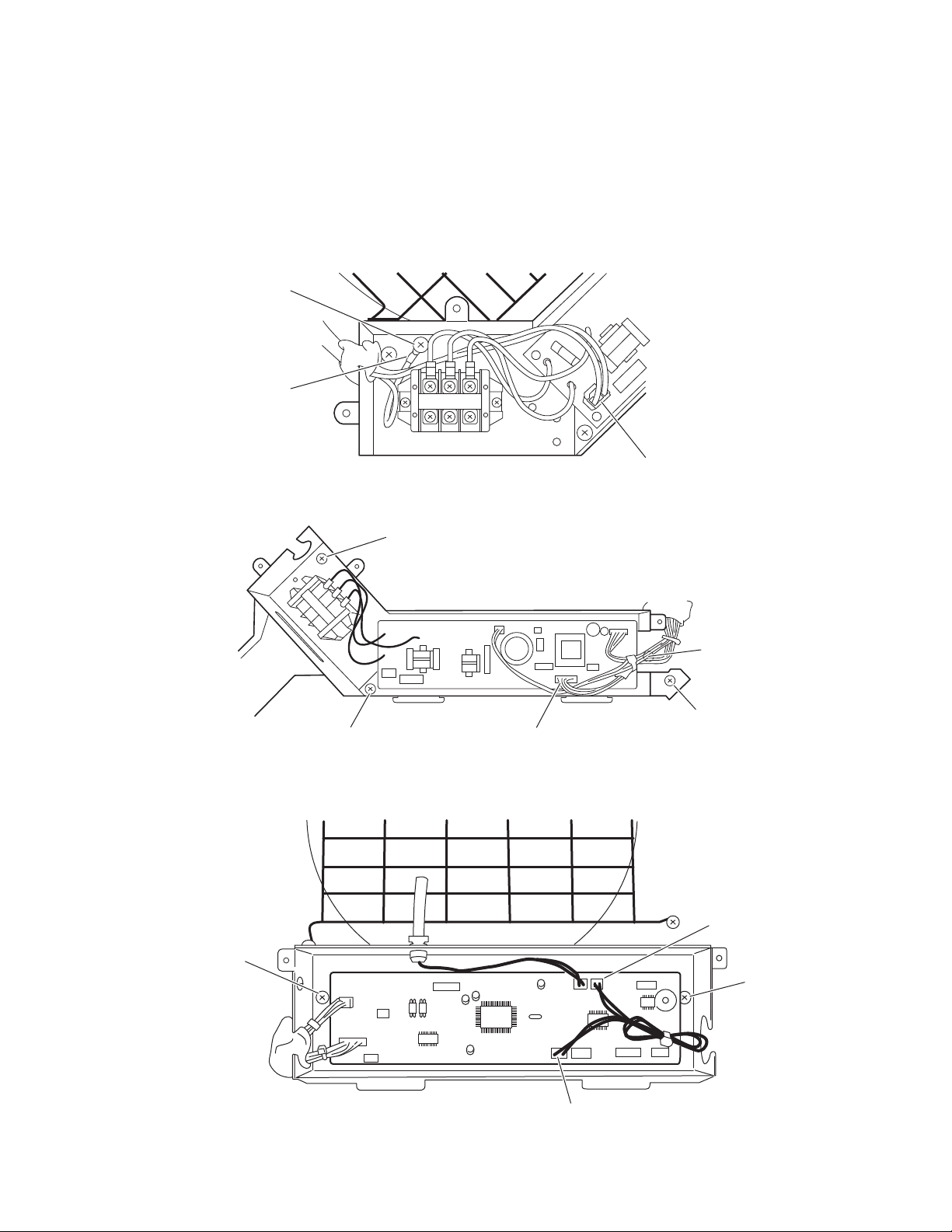
(4) Disconnect the connector CN07 (DP 2P) in the power box. (Fig. 13)
Remove a screw and disconnect the ground cable. (Fig. 13)
(5) Disconnect the connector CN03 (DCM 6P) in the power box. (Fig. 14)
(6) Remove the 4 screws and remove the power box. (Fig. 14)
(7) Disconnect the connectors CN06 (FS 3P) and CN09 (COIL-1 2P) in the control box. (Fig. 15)
(8) Remove the 2 screws and remove the control box. (Fig. 15)
Screw
Ground cable
Screw
12 3
CN07
Fig.13
Screw
Screw
Screw
CN03
Fig.14
Screw
CN09
Screw
CN06
Fig.15
24

NOTE
For the removal of the following components, perform any work after removing the indoor
unit (main body) from the ceiling.
Main body lower section Heat exchanger sensor Drain pump
Float switch Turbo fan Fan motor
Heat exchanger
1. Perform the work after draining the water to prevent the water leakage from the drain pan.
• Put a bucket, etc., under the drain cap and remove the drain cap to drain the water.
(Fig. 16)
2. Refer to the installation instructions for recovery of refrigerant or removal of the power
cable or tubing.
6-1-6. Remove the main body lower section.
(1) Remove the 4 screws. (Fig. 16)
(2) Remove the 2 screws. (Fig. 17)
(3) Disconnect the connector CN03 (DCM 6P) in the power box. (Fig. 18)
(4) Lift the main body lower section and remove it from the main body upper section.
Screw
Screw
Screw
Drain cap
Main body lower sectionMain body lower section
Screw
Fig.16
Main body lower section
Main body
upper section
Screw
CN03
Fig.18Fig.17
25
6-1-7. Remove the heat exchanger sensor.
(1) Remove the heat exchanger sensor from the sensor holder. (Fig. 19)
Fig.19
6-1-8. Remove the drain pump and float switch.
(1) Remove the 2 screws (Fig. 20)
(2) Loosen the clamp and disconnect the drain hose from the drain pump. (Fig. 20)
(3) Remove the drain pump from the main body upper section. (Fig. 20)
(4) Remove a nut and remove the float switch. (Fig. 21)
Heat exchanger sensor
Holder
Drain pump
Screw
Float switch
Nut
Drain hose
Clamp
Fig.20 Fig.21
26
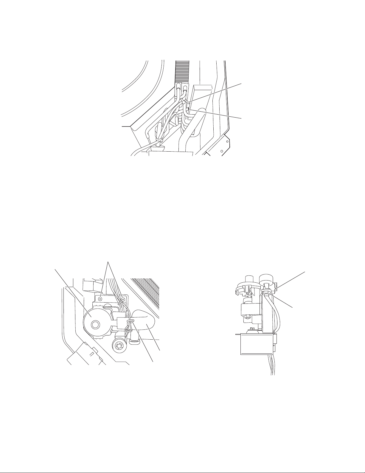
6-1-9. Remove the turbo fan and fan motor.
(1) Remove a nut and remove the turbo fan. (Fig. 22)
(2) Remove the 2 screws and 3 nuts, and remove the fan motor. (Fig. 23)
Turbo fan
Fig.22 Fig.23
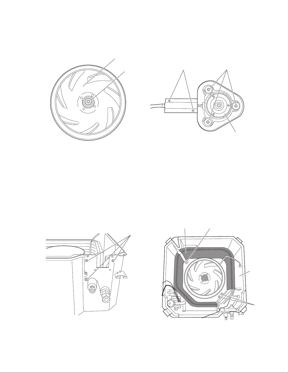
6-1-10. Remove the heat exchanger.
(1) Remove the 3 screws. (Fig. 24)
(2) Remove the 3 screws. (Fig. 25)
(3) Remove the heat exchanger from the main body upper section with the heat exchanger lifted.
Nut
Screw Nut
Fan motor
ScrewHeat exchanger
Screw
Fig.24 Fig.25
27
Main body
upper section
Screw

7. FUNCTIONS
7-1. Operation Functions
Emergency operation SENSOR DRY
Emergency operation is available when the remote
controller malfunctions, has been lost, or otherwise
cannot be used.
To operate the system, press the OPERATION button,
which is also used as the receiver, below the unit display.
Each time this button is pressed, the OPERATION lamp
changes color to indicate the type of operation. Select the
desired type of operation.
COOL HEAT STOP
(GREEN) (RED) (Lamp Off)
• The set temperature is 4°F(2°C) below the detected room
temperature in the case of cooling operation, and 4°F(2°C)
above the room temperature in the case of heating
operation. The flap and fan speed settings are AUTO.
AUTO cooling/heating operation
Selecting the operation mode
• When AUTO mode is selected, the microprocessor calculates
the difference between the set temperature and the room
temperature, and automatically switches to Cooling or
Heating mode.
Room temp. Set temp. COOL
Room temp. Set temp. HEAT
• As shown by the example in the figure below, with AUTO
cooling/heating operation, the mode changes between
Heating and Cooling mode according to changes in the
relationship between the current room temperature and the
set temperature.
During DRY operation, the system adjusts the room
temperature and fan speed according to the conditions in the
room, in order to maintain a comfortable room environment.
SENSOR DRY operation
• DRY operation is as shown in the figure below.
Load
COOL zone
A zone
B zone
Conditions are monitored at all
times when the room temperature
is below 59°F(15°C).
DRY A
The compressor operation frequency varies.
The indoor fan operates with 1/f fluctuation.
DRY B
The compressor operates at a low operating frequency.
The indoor fan operates with 1/f fluctuation.
Monitor
• Monitoring operation takes place when the room temperature
is below 59°F
(15°C), or more than 5°F(3°C) below the set
temperature.
• When the monitoring range is entered, the compressor stops,
and the indoor fan operates with 1/f fluctuation.
Example
Example of operation in AUTO mode with the set room temperature
at 74°F(23°C).
Room temp.
Set temp.
Zone A
Zone B
Zone C
74
Zone C
Zone B
Zone A
Compressor
Operation mode
More than
1 hour
ON ON ON
OFF OFF
Within
1 hour
HeatingCooling Cooling
PAM- control
• In order to further improve inverter performance, control is
switched between PWM control at low operation speeds, and
PAM control at high operation speeds, making the most
effective use of power.
28
HIGH POWER
NIGHT SETBACK
This function acts to raise the power but keeps the AC system in
the same operating mode.
This function is set with the HIGH POWER button on the remote
controller.
(It can be set regardless of the temperature and fan speed
settings.)
HIGH POWER operation from remote controller
The unit operates at maximum output for 30 minutes,
regardless of the desired temperature.
The fan speed is 1 step above "High."
Frequency
MAX
0
30 min. 5 min.
Start End
Time
NOTE
When HIGH POWER operation ends, the unit operates at low
Hz for 5 minutes, regardless of the thermostat OFF conditions.
When in DRY mode, operation is in the cooling zone.
Lamp colors
OPERATION lamp
HEAT operation Red
DRY operation Orange
COOL operation Green
FAN operation Green
DEFROSTING operation Red and Orange
alternately
OPERATION lamp Green
TIMER lamp Green
HIGH POWER lamp Green
When NIGHT SETBACK operation is set, the temperature and
fan speed settings will be adjusted automatically to allow
comfortable sleep.
When NIGHT SETBACK operation is set, " mark" appears on
the remote controller. The main unit display lamp also becomes
dimmer.
COOL and DRY modes
When the night setback mode is selected, the air conditioner
automatically raises the temperature setting 2°F(1°C) when 30
minutes have passed after the selection was made, and then
another 2°F(1°C) after another 30 minutes have passed,
regardless of the indoor temperature when night setback was
selected. This enables you to save energy without sacrificing
comfort. This function is convenient when gentle cooling is
needed.
Setting
temperature
Press the NIGHT
SETBACK button
2°F(1°C)
2°F(1°C)
30 min. 30 min.
Time
HEAT mode
When the night setback mode is selected, the air conditioner
automatically lowers the temperature setting 4°F(2°C) when 30
minutes have passed after the selection was made, and then
another 4°F(2°C) after another 30 minutes have passed,
regardless of the indoor temperature when night setback was
selected. This enables you to save energy without sacrificing
comfort. This function is convenient when gentle heating is
needed.
Setting
temperature
Press the NIGHT
SETBACK button
4°F(2°C)
30 min. 30 min.
4°F(2°C)
Time
Timer backup
Operation stops if there are no operator controls for 25 hours or
longer after unit operation switched from OFF to ON by use of
ON timer operation.
29
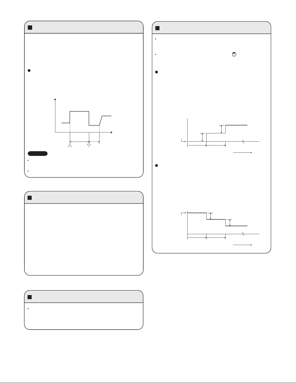
7-2. Protective Functions
Overload prevention during heating
During HEAT operation, the temperature of the indoor heat
exchanger is used to control the frequency and lessen the load
on the compressor before the protective device is activated.
Approx.
127
(53)
Approx.
117
(47)
temperature °F(°C)
Indoor heat exchanger
a.
Area: Automatic capacity control
b.
When Point A has been exceeded, the operation frequency is
A
abc d
Indoor heat exchanger
A. Control start
B. Control end
B
reduced by a certain proportion.
c.
Area: Frequency increase is prohibited.
d.
At Point B and below, overload prevention is ended and
control is the same as in the a area.
Freeze prevention
During COOL or DRY operation, freezing is detected and
operation is stopped when the temperature of the indoor heat
exchanger matches the conditions below.
1.
Freeze-prevention operation is engaged when the
temperature of the indoor heat exchanger is below 43°F(6°C).
2.
Restart after freeze-prevention operation occurs when the
temperature of the indoor heat exchanger reaches 46°F(8°C)
or above.
46
(8)
43
(6)
36
(2)
temperature °F(°C)
Indoor heat exchanger
a.
Area: Automatic capacity control
b.
When the temperature drops below Point A, the operation
*
A
abcd
frequency is reduced by a certain proportion.
c.
Area: Frequency increase is prohibited.
d.
When the temperature reaches Point C or above, freezing
prevention is ended and control is the same as in the a area.
C
B
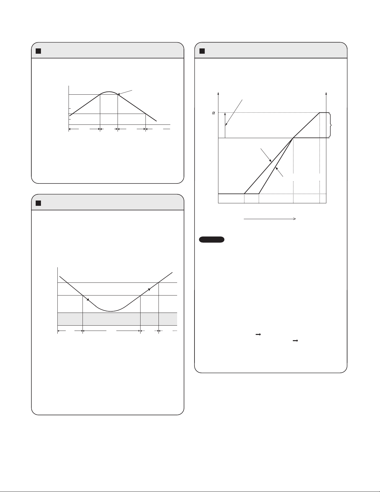
Cold-air prevention during heating
During heating, the fan speed is set to "LL" (very low) or stopped.
As the temperature of the indoor heat exchanger rises, the fan
speed is changed to the set speed.
Fan speed [rpm] Outdoor air temp.
The fan speed is increased depending
on the outside air temperature. (*1)
H +
H
LL
Stopped
At stability of operation
77
(25)86(30)
Indoor heat exchanger
temperature °F(°C)
At start of operation
TC1 100
TO1
TO2
TO3
(38)
NOTE
• The fan speed is forcibly changed to "LL" beginning 30 seconds
after the thermostat turns OFF.
• At stability of operation refers to operation when the room
temperature has approached the set temperature.
• When HEAT operation starts, the indoor fan is stopped until the
temperature of the indoor heat exchanger reaches 68°F(20°C)
or higher, or until the room temperature reaches 59°F(15°C) or
higher.
*1 It is applied only to CS-MKE9NB4U and CS-MKE12NB4U.
This function is enabled when the automatic operation is being
performed and the "Automatic Fan Speed" has been selected.
The fan speed might be increased during the automatic
operation. However, it is not the abnormal condition.
TC1 : CS-KE18NB4UW 104°F (40°C)
CS-MKE9NB4U, CS-MKE12NB4U 91°F (33°C)
TO1 : 35.6°F (2°C) or less
TO2 : 35.6°F (2°C) to 53.6°F (12°C)
TO3 : 53.6°F (12°C) or more
* When the temperature drops to below 36°F(2°C)
(continuously for 2 minutes or longer), the compressor stops.
Once the freeze condition is detected, the air conditioner will
work less than the maximum frequency until it is turned off.
30
 Loading...