

Page 1
Install
Indoor Unit
CS-ME5SD3UA
CS-ME7SD3UA
Destination
USA
Please file and use this manual together with the service manual for Model No. CU-2E18SBU, Order No. PAPAMY1604017CE.
WARNING
This service information is designed for experienced repair technicians only and is not designed for use by the general public.
It does not contain warnings or cautions to advise non-technical individuals of potential dangers in attempting to service a product.
Products powered by electricity should be serviced or repaired only by experienced professional technicians. Any attempt to service
or repair the product or products dealt with in this service information by anyone else could result in serious injury or death.
PRECAUTION OF LOW TEMPERATURE
In order to avoid frostbite, be assured of no refrigerant leakage during the installation or repairing of refrigerant circuit.
© Panasonic Corporation 2016
Page 2
11. Installation Instruction
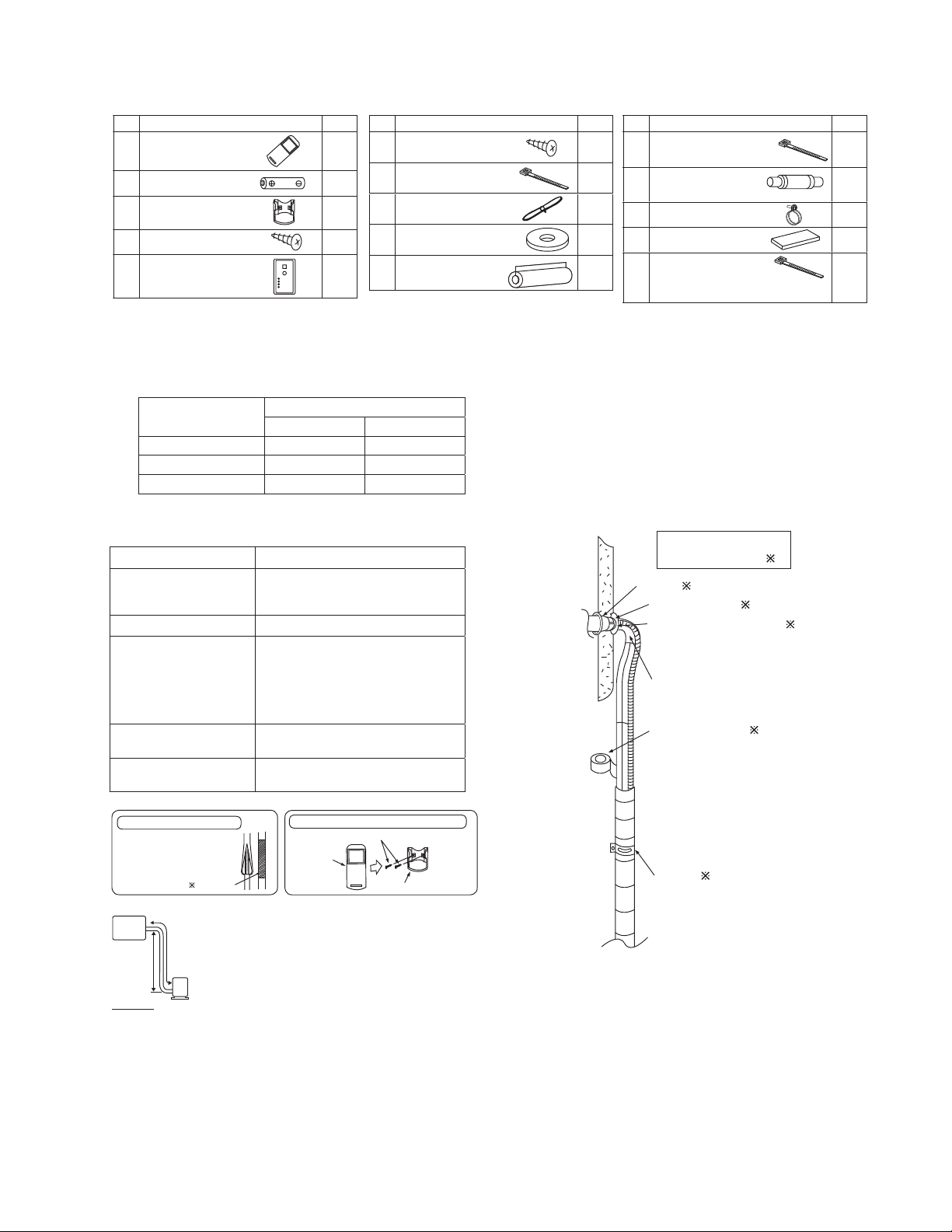
Attached Accessories
No. Accessory part Qty.
Remote control
1
Battery
2
Remote control holder
3
Remote control holder
4
fi xing screw
Remote control receiver
5
Ŷ
Required Materials
x Read the catalog and other technical materials and prepare the required materials.
x Applicable piping kit
Applicable piping kit
CZ-3F5, 7BP 3/8" (9.52 mm) 1/4" (6.35 mm)
CZ-4F5, 7, 10BP 1/2" (12.7 mm) 1/4" (6.35 mm)
CZ-52F5, 7, 10BP 5/8" (15.88 mm) 1/4" (6.35 mm)
Gas Liquid
Ŷ
Other Items to be Prepared (Locally Purchased)
Product name Remarks
Rigid PVC pipe
Adhesive PVC adhesive
Insulation
Indoor/outdoor connecting
cable
Hanging bolt related parts
VP20 (outer diameter ø1 1/32" (ø26);
also sockets, elbows and other parts
as necessary
For refrigerant piping insulation:
foamed polyethylene with a thickness
of 5/16" (8 mm) or more.
For drain piping insulation:
foamed polyethylene with a thickness
of 13/32" (10 mm) or more.
UL listed or CSA approved 4
conductor wires minimum AWG16
Hanging bolts (M10) (4) and nuts (12),
(when hanging the indoor unit)
Insulation of piping connections
• Carry out insulation after
checking for gas leaks and
secure with vinyl tape.
Vinyl tape
Indoor unit
Attaching the remote control holder to the wall
Remote control holder fi xing screws
Remote
1
control
No. Accessory part Qty.
Receiver fi xing screw
(M4 x 39/64" (15.5 mm))
6
1
Clamper (band)
7
2
1
2
1
Piping size
(for receiver cable fi xing)
Receiver cable
8
(6.56 ft (2 m))
Washer
9
(for suspension fi tting)
Flare insulator
(for gas pipe / liquid pipe
0
connection)
4
Remote control holder
3
No. Accessory part Qty.
Clamper (band)
2
1
1
8
2
(for fl are & drain insulating
!
connection)
Drain hose
(for unit & PVC pipe
@
connection)
Hose band
#
(for drain hose connection)
Drain hose insulation
$
(for drain pipe connection)
Clamper (band)
(for power supply cord)
%
* Be sure to fi x the power supply cord
with clamper (band).
Installation parts you
should purchase (
Sleeve (
Bushing-Sleeve (
Putty (Gum Type Sealer) (
Bend the pipe as closely on
the wall as possible, but be
careful that it doesn’t break.
Vinyl tape (Wide) (
• Apply after carrying
out a drainage test.
• To carry out the
drainage test,
remove the air fi lters
and pour water into
the heat exchanger.
Saddle (
4
L=131
1
1
2
1
)
)
)
)
)
)
A
B
Outdoor
unit
IMPORTANT
Begin the installation job from
the “Indoor Unit” installation.
It is advisable to avoid more than 2 blockage
directions. For better ventilation & multiple-outdoor
installation, please consult authorized dealer/specialist.
x This illustration is for explanation purposes only.
The indoor unit will actually face a different way.
x Respective outdoor unit installation procedure
shall refer to instruction manual provided in the
outdoor unit packaging.
17
Page 3

11.1 Indoor Unit
11.1.1 Selecting the Installation Location
Take into consideration the following contents when creating the blueprint.
Ŷ
Indoor unit installation location
x Do not install the unit in excessive oil fume area such as kitchen, workshop and etc.
x The location should be strong enough to support the main unit without vibration.
x There should not be any heat or steam source nearby.
x Drainage should be easy. Avoid locating the drain port close to ditches (domestic wastewater).
x Avoid locations above entrances and exits.
x Do not block the air intake and discharge passages.
x Select the location that enables the cool and warm air to spread out to the entire room.
x Locate the indoor unit at least 3.28 ft (1 m) or more away from a TV, radio, wireless appliance, antenna cable and
fluorescent light, and 6.56 ft (2 m) or more away from a telephone.
x Recommended installation height for indoor unit shall be at least 8.27 ft (2.5 m) from floor.
11.1.2 To Drill a Hole in the Wall and Install a Sleeve of Piping
1 Insert the piping sleeve to the hole.
2 Fix the bushing to the sleeve.
3 Cut the sleeve until it extrudes about 19/32"
(15 mm) from the wall.
When the wall is hollow, be sure to use the sleeve for tube
assembly to prevent pests from damaging the cables, e.g.
mice biting the connection cable.
4 Finish by sealing the sleeve with putty or
caulking compound at the final stage.
Indoor
Sleeve
for tube
assembly
3
2
/4
ø
" (ø70 mm)
through hole
Wall
Outdoor
Bushing for
19
(15 mm)
/32"
Putty or caulking compound
tube assembly
Approx.
7
" -
9/32
/32
(5 - 7 mm)
"
11.1.3 Installing the Indoor Unit (Installation Embedded in the Ceiling)
11.1.3.1 Preparation Before Installation
x Always provide sufficient entry and exit space to allow installation work, inspection and unit replacement.
x Waterproof the rear surface of the ceiling below the unit in consideration of water droplets forming and dropping.
When cooling operation is performed for an extended period under the following conditions, water droplets may form and drop. Attach locally
purchased insulation (foamed polyethylene with a thickness of 7/32" (5 mm) or more) to the outside of the indoor unit before installing into the
ceiling to improve heat insulation.
x Locations with a dew point inside the ceiling of 73.4°F (23°C) or more
x Kitchens and other locations that produce large amounts of heat and steam
x Locations where the inside of the ceiling serves as an outside air intake passage
x When installing into a ceiling, select the unit position and airflow direction that enable the cool and warm
air to spread out to the whole room.
x Do not place objects that might obstruct the airflow within 3.28 ft (1 m) below the intake grill.
18
Page 4

Required Minimum Space for Installation and Service
7
32
824) (Suspension bolt pitch)
/16" (
7
/8"
Min. 7
(
200) or
more
Min 3
564)
(
"
/32
7
22
Flange for air outlet duct
15
" (100 mm) or more for bottom
/
16
air intake
"
/8
7
or
200)
Min.
more
(
7
Min. 25/32" (20) or more
Min. 25/32" (20) or more
Electrical
component box
Inspection
access
23
/32
"
17
23
17
/32
(
450 x 450)
Refrigerant tubing
19
/32
Min. 25
(
650) or more
" (200)
/8
7
7
Ceiling
x
"
"
" (240)
/16
*H=Min.
7
9
x H dimension means the minimum height of the unit installation space.
x Select H dimension such that a downward slope of at least 1/100 is ensured. Refer to 11.1.4 “Connecting the
drain piping”
Dimension of the Indoor Unit
" (145)
/32
23
5
27
(640)
"
/16
3
25
194)
" (564) (Suspension bolt pitch)
" (
/32
/8
7
5
7
22
(38)
"
/2
1
1
(126)
"
/32
31
4
1
/4
(692) (Flange for air outlet duct)
"
3
" (640) (6
25
/16
7
/16
32
" (824) (Suspension bolt pitch)
5-ø
29
26
5
1
"
(ø3.1)(Hole)
/8
17
/32
25
/32
"
/16
" (160) x 4)
" (750)
(680)
5
1
" (29)
/32
25
3
5
2
" (66)
/8
1
1
1 15/32
5 29/32"
" (96)
/32
"
/32
(26)
1
Suspension lug
"
(37)
(150)
1
/16"
(27)
Inspection access
17
"
/32
3
6
23
17
/32" X
(450x450)
(Field supply)
(40)
"
(14)
(22)
"
/16
"
9
/16
/8
9
7
1
"
/32
23
(155)
(120)
4
"
/32
(23)
(15)
"
19
/32
29
29
"
/32
(23)
1
/8
2-ø
"
(ø3.1)
3
" (28)
1
/32
3
" (30)
/16
1
3
/16
3
" (81)
5
1
/32"
9
5
/16
(33)
1
6
(153)
"
(14)
3
/16
"
8
23
(132)
5
3
(84)
Water inlet
"
/16
"
/32
29
/32
5
" (150)
7
7
/8
" (200)
1
10-ø
"
(ø3.1)(Hole)
/8
21
"
/32
(220)
23
27
/32
* Filter Uninstalled
"
/16
21
8
(220)
" (704)
/32
"
/32
13
(Hole)
(10)
"
/8
5
5
"
/32
5
3
"
"
/16
3
1
(143)
(80)
" (44)
/32
23
1
3
5
(132)
(30)
" (238)
/8
3
9
"
/16
29
/32
9
" (14)
/16
"
(23)
19
Page 5

In Case of Bottom Intake
1 Remove the frame filter assy as shown in
diagram 1
1
Air intake
Cover plate
2
Dummy hole
2 Remove cover plate as shown in diagram 1
3 Fix frame filter assy as shown in diagram 2
4 Fix cover plate as shown in diagram 2 with
the dummy hole downward.
Air
discharge
Dummy hole
Frame Filter
Assy
Cover plate
Air discharge
Air intake
Frame
Filter
Assy
Fixing Frame Filter Assy
Main unit
Filter Assy
In case of bottom side
* Attach the frame fi lter assy to
the main unit while pushing the
tip of the latches in the direction
of the arrow.
In case of back side
Ceiling Opening
x Install inspection opening 17 23/32" x 17 23/32" (450 mm x 450 mm) on the control box side where maintenance
and inspection of the control box and drain pump are easy. Install another inspection opening 31 1/2" x 27 9/16"
(800 mm x 700 mm) also at the lower part of the unit.
9
/16
27
" (700)
700
Air
discharge
Air intake
A
Ceiling
Allow view A
Inspection access
(Field supply)
" (800)
1
800
/2
31
Securing the Hanging Bolts
Reinforced concrete
Hanging
bolt M10
/2" (114)
1
Approx.
4
Insert hole-in
anchor, etc.
”
Ceiling surface
Wooden of other structure
9
/16
1
" (40)
3
t =
" (2)
/32
3
1
" (30)
/16
(Hanging bolt pitch)
Hanging bolt
C channel
Hanging fi xture
Hanging
bolt M10
(2
Reinforcing materials
3
17
/8
" to 3
/32
" (144)
/2
1
Approx.
4
") (60 to 90 mm)
Roof beam
Ceiling surface
x Secure the hanging bolts (M10, locally purchased) firmly in a manner capable of supporting the unit weight.
x Consult your construction or interior contractor for details on finishing the ceiling opening.
20
Page 6

Installing an Intake and Discharge Duct Type
x Ensure the range of unit external static pressure is not exceeded. Refer technical manual for the range of
external static pressure setting.
x Connect the duct as shown.
x When attaching duct to the intake side, remove the product filter frame assy and replace with locally purchase
intake-side flange by using flange by using 10 - Ø 1/8" (Ø 3.1)(hole) screws.
x Wrap the flange and duct connection area with aluminium tape or similar to prevent air leak.
Flange
(locally purchase)
Connection screw (x10)
Rectangular solic duct
Main unit
Flange
Insulation material
(locally purchased)
Air outlet sideAir inlet side
When attaching a duct to the intake-side, be sure to attach
an air filter inside the air passage on the intake-side.
(Use an air filter with dust collecting efficiency at least 50%
in a gravimetric technique.)
Installation into the Ceiling
x Attach the nuts and washers to the hanging bolts, then lift up and hook the main unit onto the hanging fixtures.
x Check if the unit is leveled using a level or a vinyl hose filled partially with water.
Hanging bolt (M10)
(locally purchased)
Washer
9
Level
Hexagonal nut (M10)
(locally purchased)
21
Page 7

Mounting Remote Controller Receiver
Install the remote controller receiver cable at least 1 31/32" (50 mm) away from electric wires of other appliances to avoid miss-operation
(electromagnetic noise).
1 Remove the bottom case.
Insert the driver
and slightly turn.
Bottom
case
Flat-blade
screwdriver
2 Mount to the wall.
Attention
Mounting the bottom case
Screws
6
x Tighten the screws securely until the screw heads
touch the bottom case. (Otherwise, loose screw
heads may hit the PCB and cause malfunction
when mounting the top case.)
x Do not over-tighten the screws. (The bottom case
may be deformed, resulting in fall of the unit.)
Connecting the remote control wiring
x Arrange the wires as shown in the illustration for
2 as in diagram below, avoiding unnecessary
wires being stored in the case. (Caught wires may
destroy the PCB.)
x Avoid wires touching parts on the PCB. (Caught
wires may destroy the PCB.)
EXPOSED TYPE
Preparation: Make 2 holes for screws using a driver.
Mount the top case.
• Align the claws of the
top case and then align
the claws of the bottom
case.
Cut here with
a nipper and
remove the burr
with a fi le.
Mount the bottom case
to the wall.
Preparation: Make 2 holes for screws using a driver.
Mount the top case.
• Align the claws of the
top case and then
align the claws of the
bottom case.
Avoid the wire
being caught.
Claw (2 places)
EMBEDDED TYPE
Mount the bottom case to the wall.
• Pass the wire through the hole in
the centre of the bottom case.
Claw (2 places)
Wood screw (supplied)
Connect the remote control wiring.
• Arrange the wires along the groove of the case.
Top case
(Back side)
Bottom case (Back side)
Claw
Hole for screw
Wall to fi x the
receiver
Clamper
(supplied)
Pass
through
the hole
Claw
Top case
(Back side)
Hole for screw
Terminal board
Wood screw (supplied)
Connect the remote control wiring.
7
Bottom case (Back side)
22
Page 8

x Connect the indoor unit and the remote control receiver 5. (Refer to the illustration.)
x Fix the green wire from receiver cable 8 to the grounding location provided inside control board.
Receiver cable 8
Control box
Remote control
5
receiver
11.1.4 Connecting the Drain Piping
x Lay the drain piping so as to ensure drainage.
x Use a locally purchased VP20 general rigid PVC pipe (outer diameter ø1 1/32" (ø26)) for the drain piping and
firmly connect the indoor unit and the drain piping using supplied hose band to ensure that no leakage
occurs.
x Drain piping located indoor should always be insulated by wrapping with locally purchased insulation (foamed
polyethylene with a thickness of 13/32" (10 mm) or more).
x The drain piping should have a downward gradient (1/100 or more) and should be secured by using pipe hanging
equipment to avoid creating hills or traps partway.
x Should there be any obstacle preventing the drain piping from being extended smoothly, the drain piping can be
raised outside of the main unit as shown in the illustration below.
Rise
Hill
Unit drain port
Hose band
#
Hard PVC pipe (VP20)
Do not use adhesive.
x Strictly do not install and extend the drain piping from the main unit drain water outlet horizontally or upward or raised it 19 11/16" (500 mm)
or more.
Doing so may result in poor drainage or drain motor failure.
x Do not use drain hose bent at 90° angle. (The maximum permissible bend is 45°.)
Drain hose
Drain hose insulation
1
/32" (26)
1
1
/8
5
1
1
" (130)
@
"
/32
(26)
Adhere with
PVC adhesive.
$
Tr ap
13
11
" (300 mm) or less
At least 1/100
Good
/16
(not a downward gradient)
11
/16
19
" (500 mm) or less
11.1.5 Insulating the Refrigerant Piping
x After the piping is connected, insulate. (Refer to the illustration)
Clamper
Wrap fi rmly
with vinyl tape,
leaving no gaps.
Unit side
!
Wrap fi rmly
with vinyl tape,
leaving no gaps.
Flare insulator
0
23
Page 9

11.1.6 Connect the Cable to the Indoor Unit
x Remove control box cover.
x Remove the plugs.
x Fix the conduit connections to the knockout holes
together with lock nuts, then secure them against
the control box side panel.
x Receiver cable wires 8 must pass through the
upper conduit hole.
Make sure the receiver cable is inserted from
inside of the control box.
Connect receiver cable connector to control box
wire connector and fix it to the power supply cord
holder as shown in the diagram.
Insert firmly the connector of receiver cable 8 to
connector at control box of indoor unit.
x Connection cable between indoor unit and
outdoor unit should be UL listed or CSA approved
4 conductor wires minimum AWG16 in
accordance with local electric codes.
o Ensure that the terminal numbers on the
indoor unit are connected to the same
terminal numbers on the outdoor unit by the
right coloured wires as shown in the diagram.
o Earth lead wire should be longer than the
other lead wires as shown in the diagram for
electrical safety purpose in case the cord slips
out from the anchorage.
o Secure the cable onto the control board with
the holder (clamper).
Terminals on the indoor unit 1 2 3
Colour of wires
Terminals on the outdoor unit 1 2 3
When the wall is hollow, please be sure to use the sleeve
for tube ass’y to prevent dangers caused by mice biting the
connection cable.
Lock Nuts
Control Box
Control Box cover
Knockout holes
Screws
Plugs
Connectors
Fix the receiver cable to the holderFix receiver cable connector
Earth wire
(connection cable)
Indoor/outdoor connection terminal
Holder for
connection cable
Earth wire
(receiver cable)
Indoor/outdoor
connection cable
WARNING
This equipment must be properly earthed.
x Ensure the colour of wires of outdoor unit and the
terminal Nos. are the same to the indoor’s
respectively.
x Earth wire shall be Yellow/Green (Y/G) in colour
and longer than other AC wires for safety reason.
24
Page 10

11.1.6.1 Wire Stripping and Connecting Requirement
Wire stripping
Indoor/outdoor
connection
terminal board
7
10 ± 1 mm
13/32" ± 1/32"
No loose strand when inserted
Do not joint wires
/32" (5 mm)
or more
(gap between wires)
Conductor
fully inserted
ACCEPT PROHIBITED PROHIBITED
Conductor
over inserted
Conductor not
fully inserted
OR
OR
WARNING
RISK OF FIRE
JOINING OF WIRES MAY CAUSE
OVERHEATING AND FIRE.
OR
Use complete wire without joining.
Use approved socket and plug with earth pin.
Wire connection in this area must follow to national wiring rules.
Switching the High State Switch (SW2)
x To increase the air volume, open the control box and on the control board, switch the FAN switch (SW2) to “HI”.
x See the diagram for “Connecting the Indoor/Outdoor Connection Cable”.
Note: Enabling Long-range Remote Control
x To maintain EMC emission limits, cabling interconnecting the HA terminal and subsequent opto-coupler, must be
no more than 6.2 ft (1.9 m) length.
x Loop four turns of this cable through a suitable small EMC ferrite toroid, and protect with a short length of large
diameter heat-shrink tube.
x There is no similar length limit for cable following on from the opto-coupler isolation.
CHECK THE DRAINAGE
Check after connecting the power supply.
x Pour approximately 600 cc of water into the drain
pan of the main unit using a squeeze bottle, etc.
x Press the drain test run switch on the control
board in the control box to start the drain motor
and check whether the water drains normally.
(The drain motor operates for approximately
5 minutes and then stops automatically.)
(See the diagram for “Connecting the
Indoor/Outdoor Connection Cable”.)
Heat
exchanger
Squeeze bottle
Approximately
600 cc of water
Drain pan
25
 Loading...