

Page 1
Order No. RAC0504012C2
Air Conditioner
CS-HE9DKE CU-HE9DKE
CS-HE12DKE CU-HE12DKE
CONTENTS
Page Page
1 Features 2
2 Functions
2.1. Remote Control
2.2. Indoor Unit
2.3. Outdoor unit
3 Product Specifications
4 Dimensions
4.1. Indoor Unit / Remote Control
4.2. Outdoor Unit
5 Refrigeration Cycle Diagram
6 Block Diagram
7 Wiring Diagram
7.1. Indoor Unit
10
10
11
12
13
14
14
3
3
4
5
6
7.2. Outdoor Unit 15
8 Electronic Circuit Diagram
8.1. Indoor Unit / Remote Controller
8.2. Outdoor Unit
9 Operation Details
9.1. Basic Function
9.2. Indoor Power Relay Control
9.3. Room Temperature Control (Compressor Control)
9.4. Airflow Direction Control
9.5. Quiet operation (Cooling Mode / Cooling area of Dry
Mode)
9.6. Indoor Fan Control
9.7. Powerful Operation
© 2005 Matsushita Electric Industrial Co., Ltd. All
rights reserved. Unauthorized copying and
distribution is a violation of law.
16
16
18
20
20
21
22
23
26
28
30
Page 2
CS-HE9DKE CU-HE9DKE / CS-HE 12DKE CU-HE12DKE
9.8. Automatic Operation 31
9.9. Sleep Timer Operation
9.10. Timer Operation
9.11. Auto Restart Control
9.12. Ionizer Operation
9.13. Oxygen Enrich Operation
9.14. Deice Control <Heating>
9.15. Protection Control
10 Operating Instructions
11 Installation Instructions
11.1. Safety Precautions
11.2. Indoor Unit
11.3. Outdoor Unit
12 Installation and Servicing Air Conditioner Using R410A
12.1. Outline
1 Features
•
•
Product
• •
−
−
Telecommunication Support.
− −
−
−
Air Swing to adjust vertical or horizontal airflow louver.
− −
−
−
Four modes of operation selection.
− −
−
−
Air filter with function to reduce dust and smoke.
− −
−
−
Supersonic air purifying device (Super Alleru-buster)
− −
operation.
−
−
Remote control unit holder.
− −
−
−
Remote control self-illuminating button.
− −
−
−
Ionizer control to provide fresh air effect by generating
− −
negative ion.
−
−
Powerful mode to achieve setting temperature quickly
− −
room.
−
−
Quiet mode to provide quiet operation (Lo: -3dB).
− −
−
−
Oxygen mode to supply oxygen enrich air to indoor
− −
room.
−
−
24-hour real-timer setting.
− −
−
−
Long installation piping up to 15 meters.
− −
−
−
Guard net provided in Outdoor unit
− −
12.2. Tools For Installing/Servicing Refrigerant Piping 56
32
32
32
33
34
36
37
39
45
45
48
52
55
55
12.3. Refrigerant Piping Work
12.4. Installation, Transferring, Servicing
13 Servicing Information
13.1. About Lead Solder (PbF)
13.2. Troubleshooting
13.3. Disassembly of Parts
14 Technical Data
14.1. Operation Characteristics
14.2. Sensible Capacity Chart
15 Exploded View and Replacement Parts List
15.1. Exploded View (Indoor Unit)
15.2. Replacement Parts List (Indoor Unit)
15.3. Exploded View (Outdoor Unit)
15.4. Replacement Parts List (Outdoor Unit)
60
63
67
67
68
72
81
81
83
84
84
85
86
87
•
•
Quality Improvement
• •
−
−
Random auto restart after power failure for safety restart
− −
operation.
−
−
Blue Coated Condenser for high resistance to corrosion.
− −
•
•
Serviceability
• •
−
−
Removable and washable front panel.
− −
−
−
Breakdown self diagnosis function .
− −
•
•
Environmental Protection
• •
−
−
Non-ozone depletion substances refrigerant (R410A).
− −
2
Page 3

2 Functions
2.1. Remote Control
CS-HE9DKE CU-HE9DKE / CS-HE 12DKE CU-HE12DKE
3
Page 4
CS-HE9DKE CU-HE9DKE / CS-HE 12DKE CU-HE12DKE
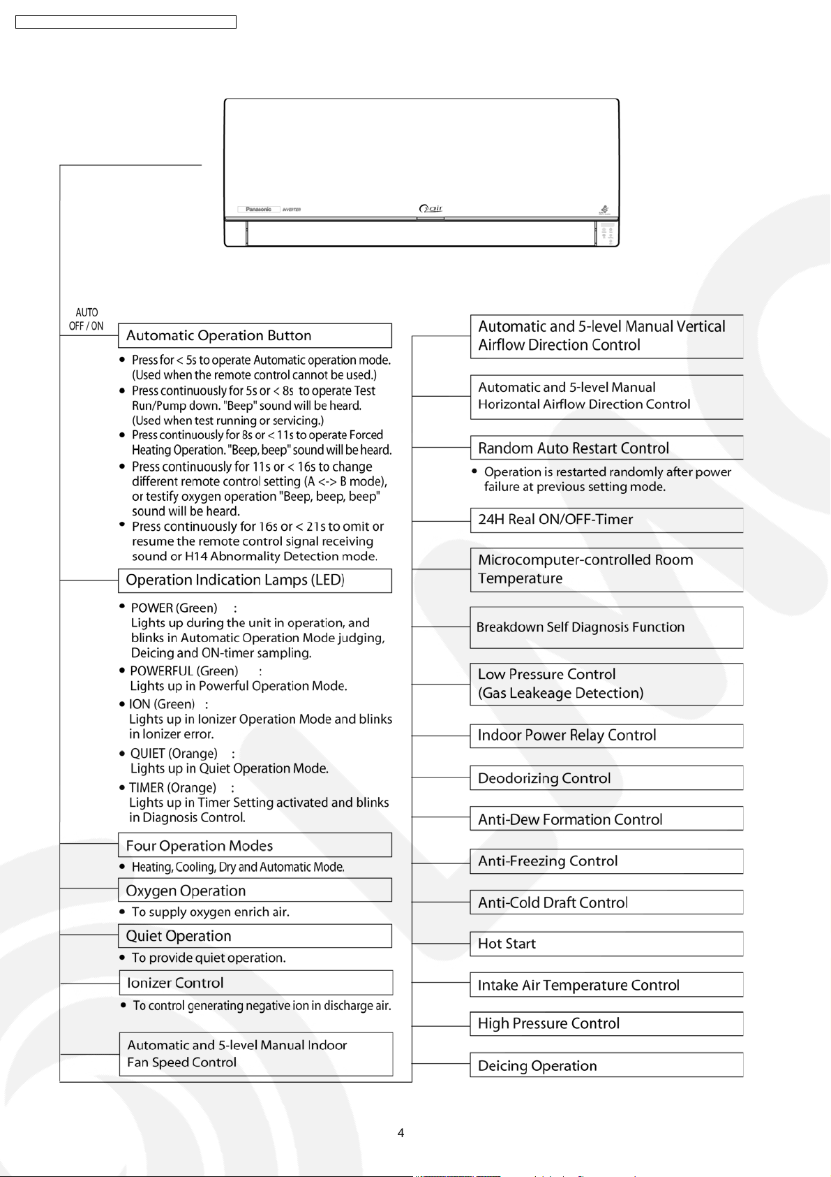
2.2. Indoor Unit
4
Page 5
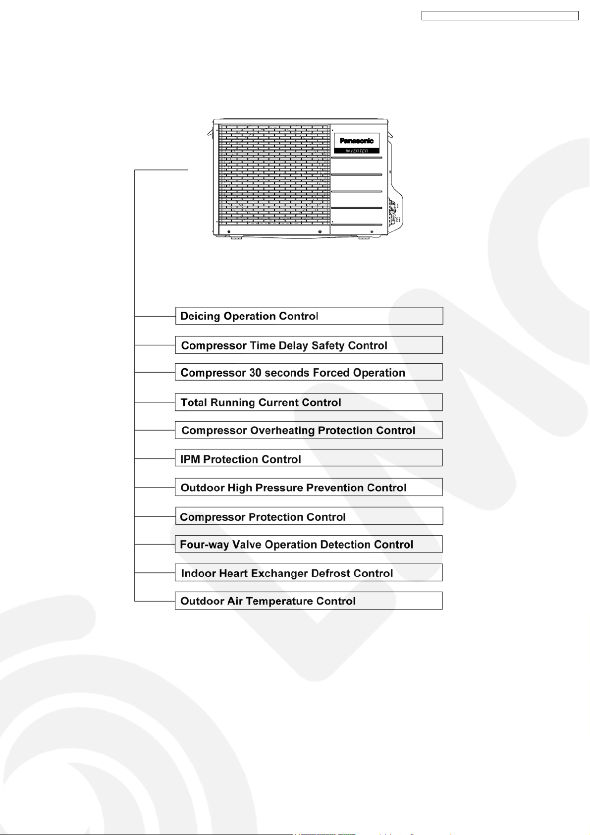
2.3. Outdoor unit
CS-HE9DKE CU-HE9DKE / CS-HE 12DKE CU-HE12DKE
5
Page 6

CS-HE9DKE CU-HE9DKE / CS-HE 12DKE CU-HE12DKE
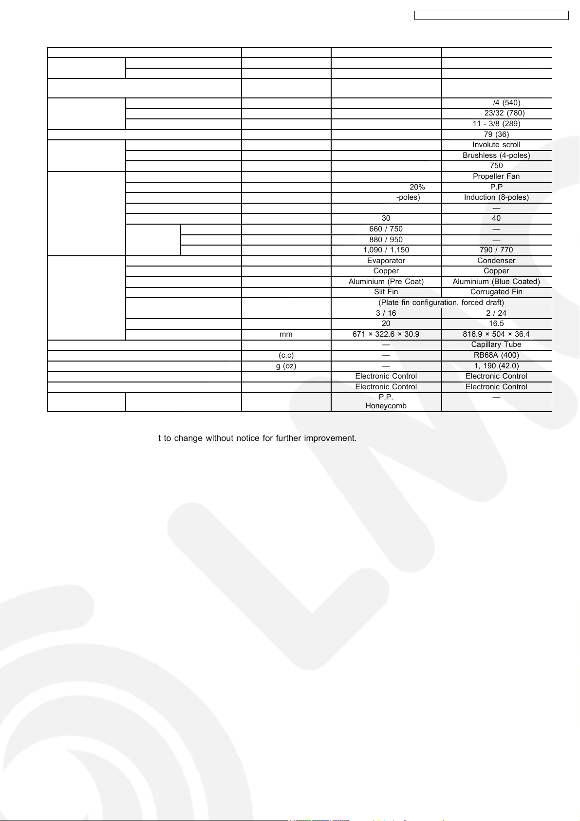
3 Product Specifications
Unit CS-HE9DKE CU-HE9DKE
Cooling Capacity kW
kcal/h
BTU/h
Heating Capacity kW
kcal/h
BTU/h
Moisture Removal l/h
Pint/h
Power Source Phase
V
Cycle
Airflow Method OUTLET
INTAKE
2.60 (0.60 - 3.00)
2,240 (520 - 2,580)
8,870 (2,050 - 10,200)
3.60 (0.60 - 6.50)
3,100 (520 - 5,590)
12,300 (2,050 - 22,080)
1.5
(3.2)
Single
230/240
50
SIDE VIEW TOP VIEW
Air Volume Indoor Air (Lo) m3/min (cfm) Cooling; 5.2 (180) —
Heating; 6.3 (220)
Indoor Air (Me) m3/min (cfm) Cooling; 7.9 (280) —
Heating; 8.8 (310)
Indoor Air (Hi) m3/min (cfm) Cooling; 10.5 (370) Cooling; 23.8 (840)
Heating; 11.5 (410) Heating; 23.1 (820)
dB (A) Cooling; High 39, Low 26 Cooling; 46
Heating; High 40, Low 27 Heating; 47
Noise Level
Power level dB Cooling; High 50 Cooling; High 59
Heating; High 51 Heating; High 60
Electrical Data Input W Cooling; 510 (120 - 700)
Heating; 690 (115 - 1,720)
Running Current A Cooling; 2.6
Heating; 3.5
Piping Connection Port
(Flare piping)
Pipe Size
(Flare piping)
EER W/W (kcal/hw), BTU/hw Cooling; 5.10 (4.39), 17.4
COP W/W (kcal/hw), BTU/hw Heating; 5.22 (4.49), 17.8
Starting Current A 3.6
inch
inch
inch
inch
G ; Half Union 3/8”
L ; Half Union 1/4”
G (gas side) ; 3/8”
L (liquid side) ; 1/4”
G ; 3-way valve 3/8”
L ; 2-way valve 1/4”
G (gas side) ; 3/8”
L (liquid side) ; 1/4”
6
Page 7
CS-HE9DKE CU-HE9DKE / CS-HE 12DKE CU-HE12DKE
Unit CS-HE9DKE CU-HE9DKE
Drain
Hose
Power Cord Length
Number of core-wire
Dimensions Height inch (mm) 11 - 23/32 (298) 21 - 1/4 (540)
Net Weight lb (kg) 24 (11) 79 (36)
Compressor Type — Involute scroll
Air Circulation Type Cross-flow Fan Propeller Fan
Heat Exchanger Description Evaporator Condenser
Refrigerant Control Device — Capillary Tube
Refrigeration Oil (c.c) — RB68A (400)
Refrigerant (R410A) g (oz) — 1, 190 (42.0)
Thermostat Electronic Control Electronic Control
Protection Device Electronic Control Electronic Control
Air Filter Material
Inner diameter mm 16 —
Length m 0.65 —
3-core wires × 1.0 mm
Width inch (mm) 34 - 8/32 (870) 30 - 23/32 (780)
Depth inch (mm) 7 - 27/32 (199) 11 - 3/8 (289)
Motor Type — Brushless (4-poles)
Rated Output W — 750
Material AS + Glass Fiber 20% P.P
Motor Type Transistor (8-poles) Induction (8-poles)
Input W — —
Rate Output W 30 40
Fan Speed Lo (Cool/Heat) rpm 660 / 750 —
Me (Cool/Heat) rpm 880 / 950 —
Hi (Cool/Heat) rpm 1,090 / 1,150 790 / 770
Tube material Copper Copper
Fin material Aluminium (Pre Coat) Aluminium (Blue Coated)
Fin Type Slit Fin Corrugated Fin
Row / Stage (Plate fin configuration, forced draft)
FPI 20 16.5
Size (W × H × L) mm 671 × 322.6 × 30.9 816.9 × 504 × 36.4
Style
1.8 m
3/16 2/24
P.P.
Honeycomb
2
—
—
—
•
•
Specifications are subject to change without notice for further improvement.
• •
7
Page 8
CS-HE9DKE CU-HE9DKE / CS-HE 12DKE CU-HE12DKE
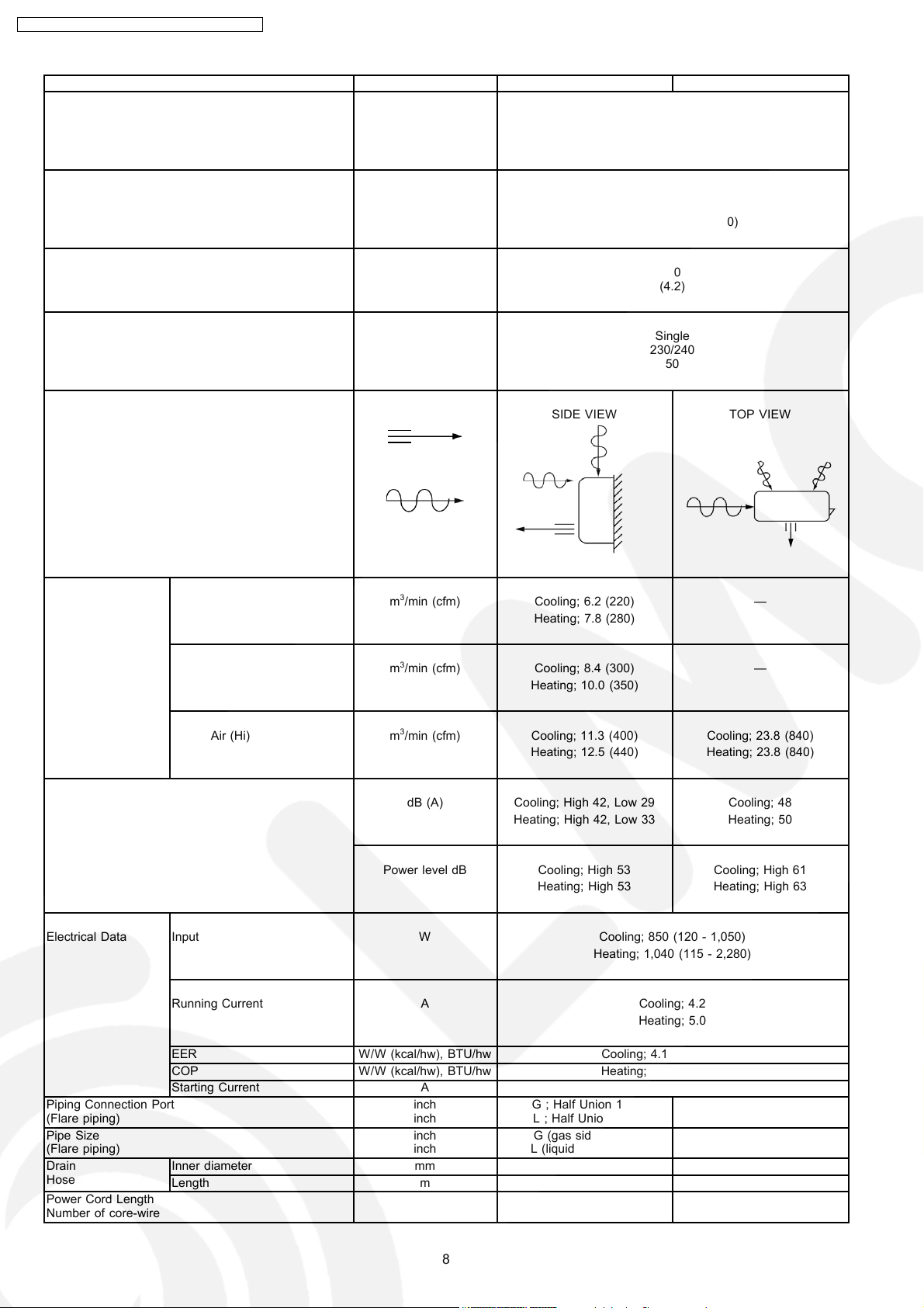
Unit CS-HE12DKE CU-HE12DKE
Cooling Capacity kW
kcal/h
BTU/h
Heating Capacity kW
kcal/h
BTU/h
Moisture Removal l/h
Pint/h
Power Source Phase
V
Cycle
Airflow Method OUTLET
INTAKE
3.50 (0.60 - 4.00)
3,010 (520 - 3,440)
11,900 (2,050 - 13,600)
4.80 (0.60 - 7.70)
4,130 (520 - 6,620)
16,400 (2,050 - 26,100)
2.0
(4.2)
Single
230/240
50
SIDE VIEW TOP VIEW
Air Volume Indoor Air (Lo) m3/min (cfm) Cooling; 6.2 (220) —
Heating; 7.8 (280)
Indoor Air (Me) m3/min (cfm) Cooling; 8.4 (300) —
Heating; 10.0 (350)
Indoor Air (Hi) m3/min (cfm) Cooling; 11.3 (400) Cooling; 23.8 (840)
Heating; 12.5 (440) Heating; 23.8 (840)
dB (A) Cooling; High 42, Low 29 Cooling; 48
Heating; High 42, Low 33 Heating; 50
Noise Level
Power level dB Cooling; High 53 Cooling; High 61
Heating; High 53 Heating; High 63
Electrical Data Input W Cooling; 850 (120 - 1,050)
Heating; 1,040 (115 - 2,280)
Running Current A Cooling; 4.2
Heating; 5.0
Piping Connection Port
(Flare piping)
Pipe Size
(Flare piping)
Drain
Hose
Power Cord Length
Number of core-wire
EER W/W (kcal/hw), BTU/hw Cooling; 4.12 (3.54), 14.0
COP W/W (kcal/hw), BTU/hw Heating; 4.62 (3.97), 15.8
Starting Current A 5
inch
inch
inch
inch
G ; Half Union 1/2”
L ; Half Union 1/4”
G (gas side) ; 1/2”
L (liquid side) ; 1/4”
G ; 3-way valve 1/2”
L ; 2-way valve 1/4”
G (gas side) ; 1/2”
L (liquid side) ; 1/4”
Inner diameter mm 16 —
Length m 0.65 —
3-core wires × 1.5 mm
1.8 m
2
8
—
—
Page 9

CS-HE9DKE CU-HE9DKE / CS-HE 12DKE CU-HE12DKE
Unit CS-HE12DKE CU-HE12DKE
Dimensions Height inch (mm) 11 - 23/32 (298) 21 - 1/4 (540)
Width inch (mm) 34 - 8/32 (870) 30 - 23/32 (780)
Depth inch (mm) 7 - 27/32 (199) 11 - 3/8 (289)
Net Weight lb (kg) 24 (11) 82 (37)
Compressor Type — Involute scroll
Motor Type — Brushless (4-poles)
Rated Output W — 1,100
Air Circulation Type Cross-flow Fan Propeller Fan
Material AS + Glass Fiber 20% P.P
Motor Type Transistor (8-poles) Induction (8-poles)
Input W — —
Rate Output W 30 40
Fan Speed Lo (Cool/Heat) rpm 740 / 870 —
Me (Cool/Heat) rpm 920 / 1,050 —
Hi (Cool/Heat) rpm 1,110 / 1,230 790 / 790
Heat Exchanger Description Evaporator Condenser
Tube material Copper Copper
Fin material Aluminium (Pre Coat) Aluminium (Blue Coated)
Fin Type Slit Fin Corrugated Fin
Row / Stage (Plate fin configuration, forced draft)
3/16 2/24
FPI 20 16.5
Size (W × H × L) mm 671 × 322.6 × 30.9 671 × 322.6 × 30.9
Refrigerant Control Device — Capillary Tube
Refrigeration Oil (c.c) — RB68A (400)
Refrigerant (R410A) g (oz) — 1,160 (40.9)
Thermostat Electronic Control Electronic Control
Protection Device Electronic Control Electronic Control
Air Filter Material
Style
P.P.
Honeycomb
—
•
•
Specifications are subject to change without notice for further improvement.
• •
9
Page 10
CS-HE9DKE CU-HE9DKE / CS-HE 12DKE CU-HE12DKE
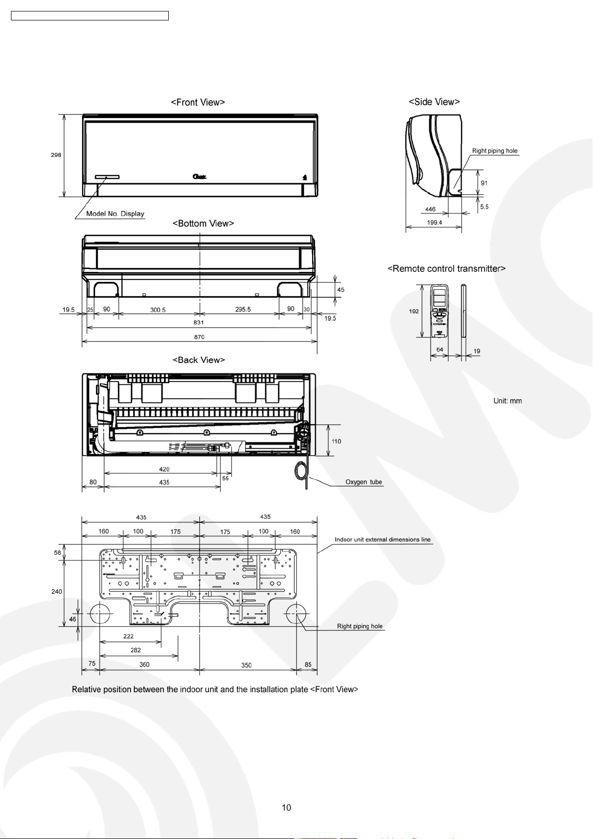
4 Dimensions
4.1. Indoor Unit / Remote Control
10
Page 11

4.2. Outdoor Unit
CS-HE9DKE CU-HE9DKE / CS-HE 12DKE CU-HE12DKE
11
Page 12
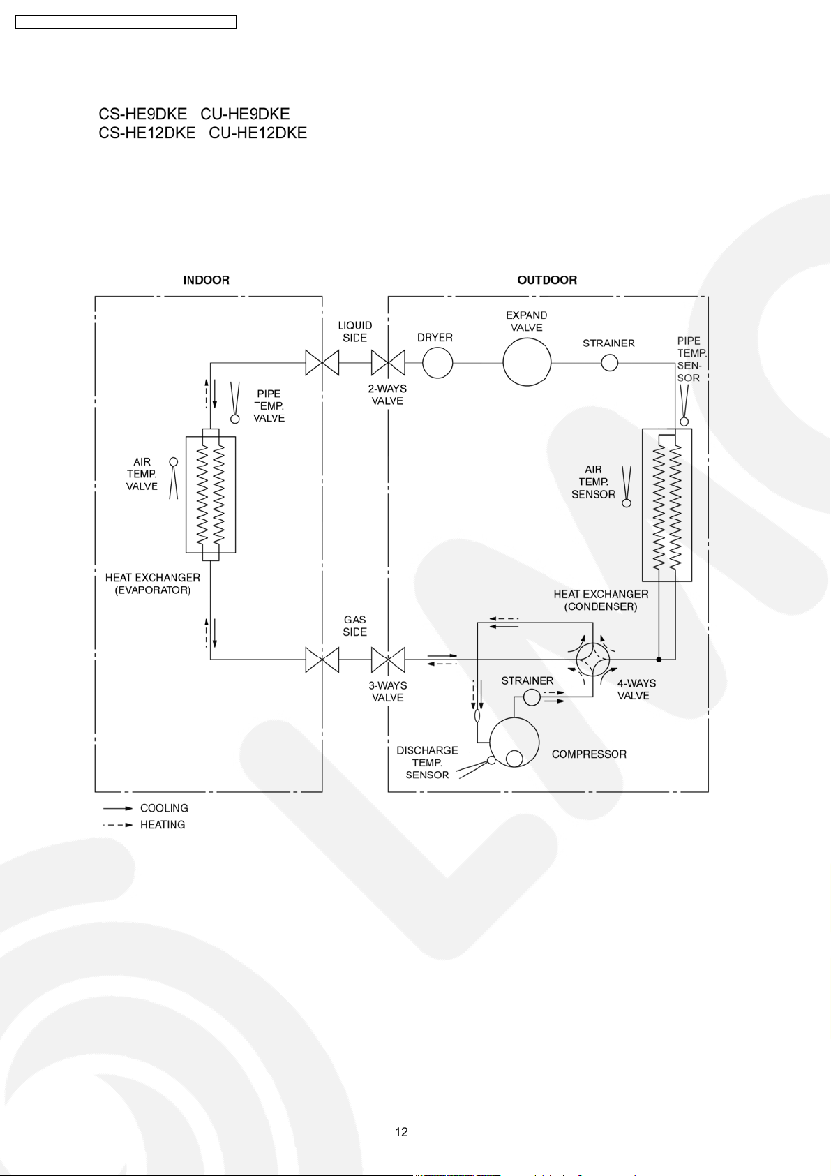
CS-HE9DKE CU-HE9DKE / CS-HE 12DKE CU-HE12DKE
5 Refrigeration Cycle Diagram
12
Page 13

6 Block Diagram
CS-HE9DKE CU-HE9DKE / CS-HE 12DKE CU-HE12DKE
13
Page 14
CS-HE9DKE CU-HE9DKE / CS-HE 12DKE CU-HE12DKE
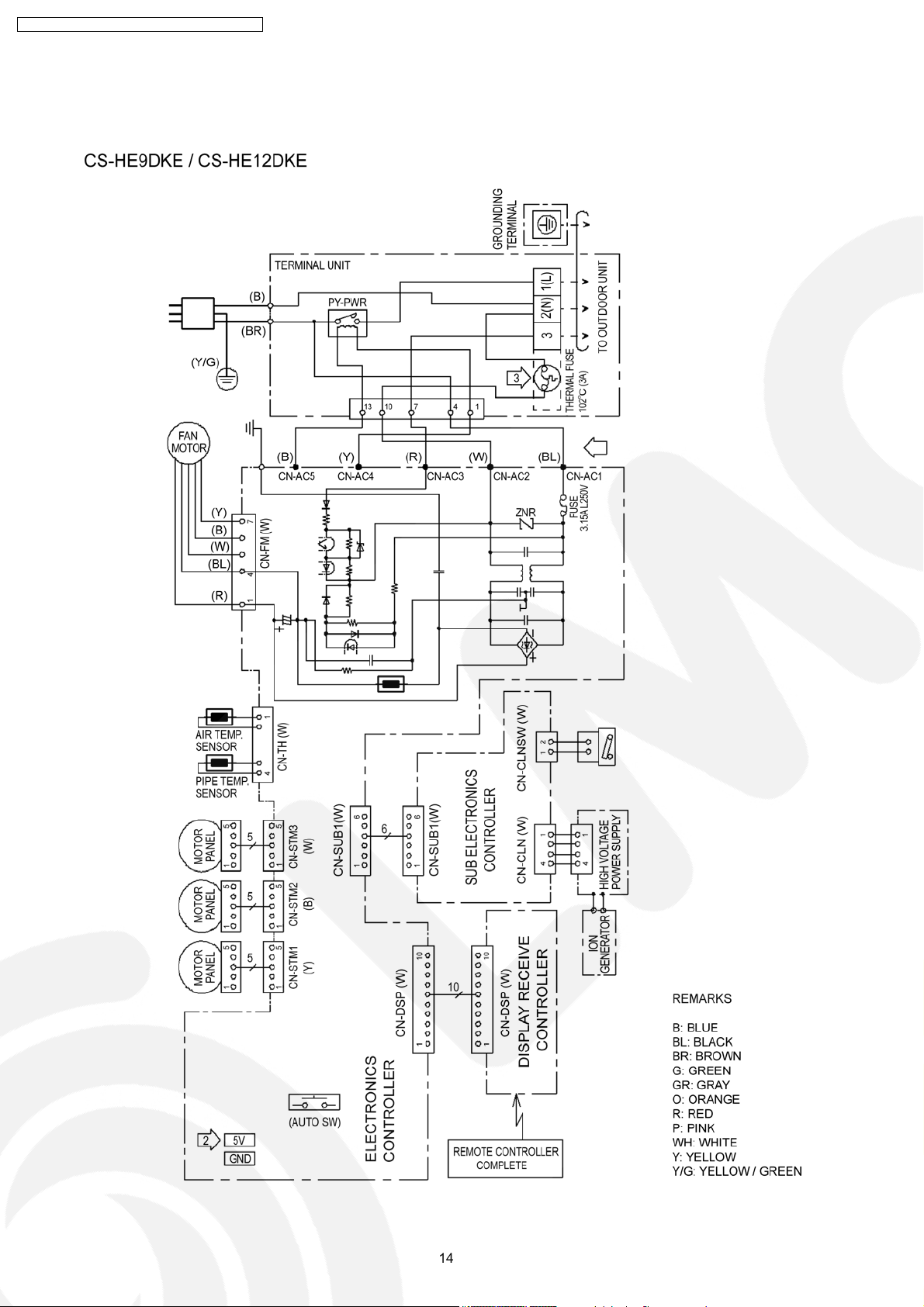
7 Wiring Diagram
7.1. Indoor Unit
14
Page 15
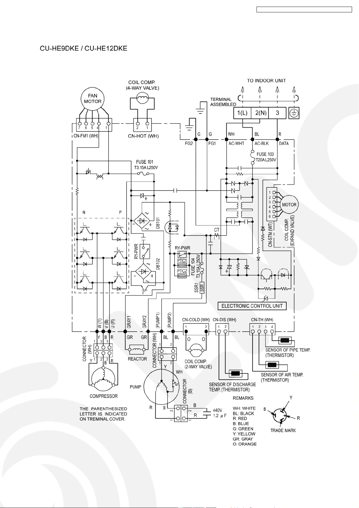
7.2. Outdoor Unit
CS-HE9DKE CU-HE9DKE / CS-HE 12DKE CU-HE12DKE
15
Page 16
CS-HE9DKE CU-HE9DKE / CS-HE 12DKE CU-HE12DKE
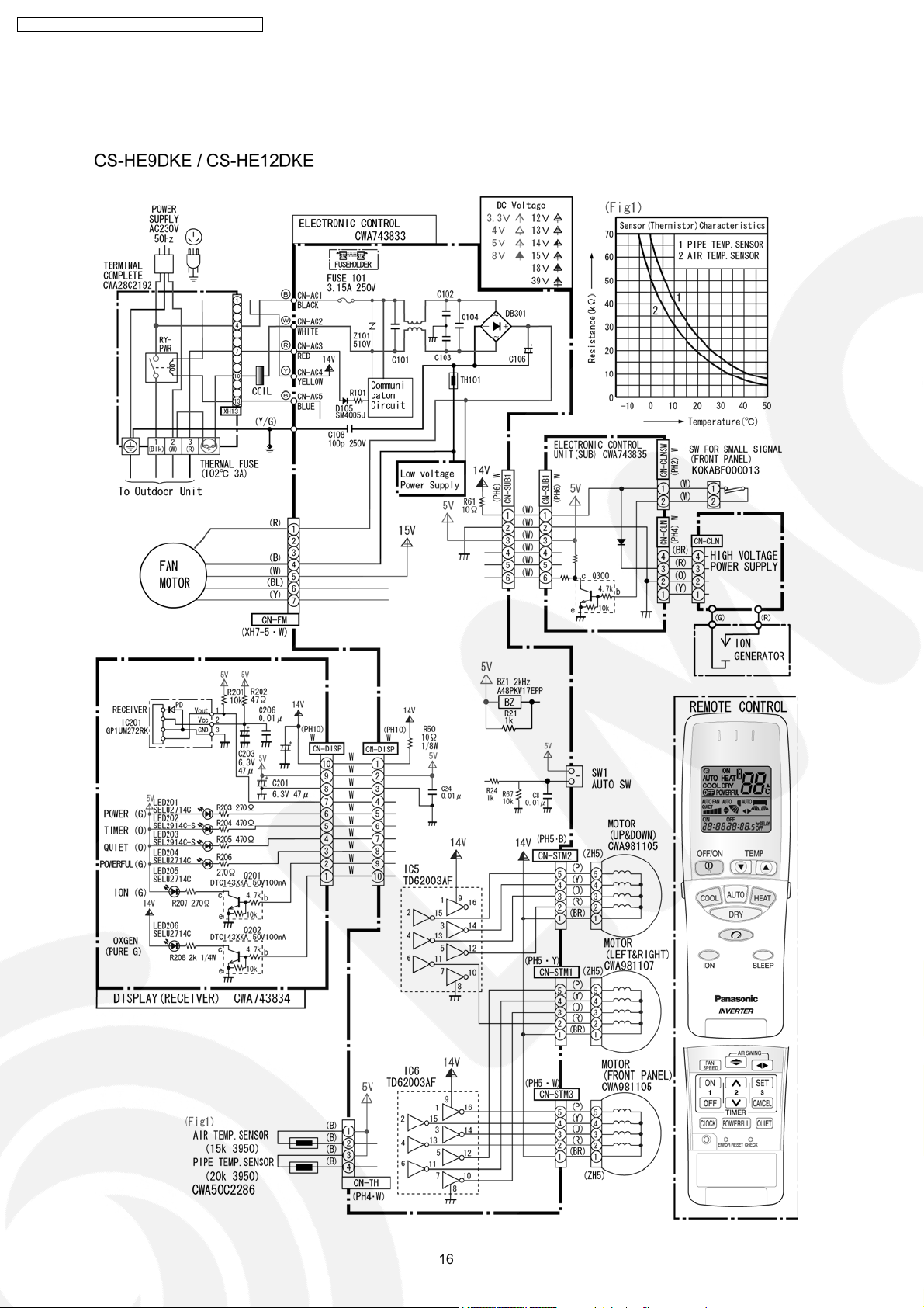
8 Electronic Circuit Diagram
8.1. Indoor Unit / Remote Controller
16
Page 17
CS-HE9DKE CU-HE9DKE / CS-HE 12DKE CU-HE12DKE
17
Page 18
CS-HE9DKE CU-HE9DKE / CS-HE 12DKE CU-HE12DKE
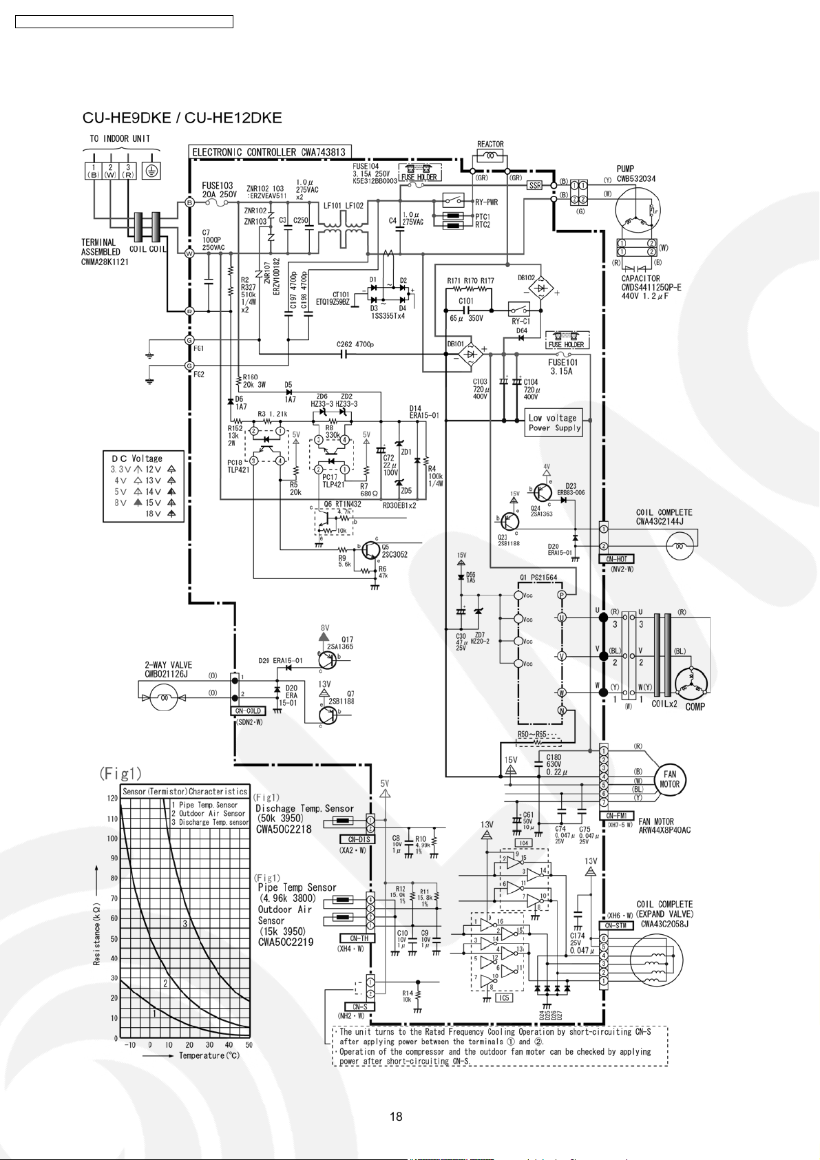
8.2. Outdoor Unit
18
Page 19
CS-HE9DKE CU-HE9DKE / CS-HE 12DKE CU-HE12DKE
19
Page 20
CS-HE9DKE CU-HE9DKE / CS-HE 12DKE CU-HE12DKE
9 Operation Details
9.1. Basic Function
Inverter control, which equipped with a microcomputer in determining the most suitable operating mode as time passes,
automatically adjusts output power for maximum comfort always. In order to achieve the suitable operating mode, the
microcomputer maintains the set temperature by measuring the temperature of the environment and performing temperature
shifting. The compressor at outdoor unit is operating following the frequency instructed by the microcomputer at indoor unit that
judging the condition according to internal setting temperature and intake air temperature.
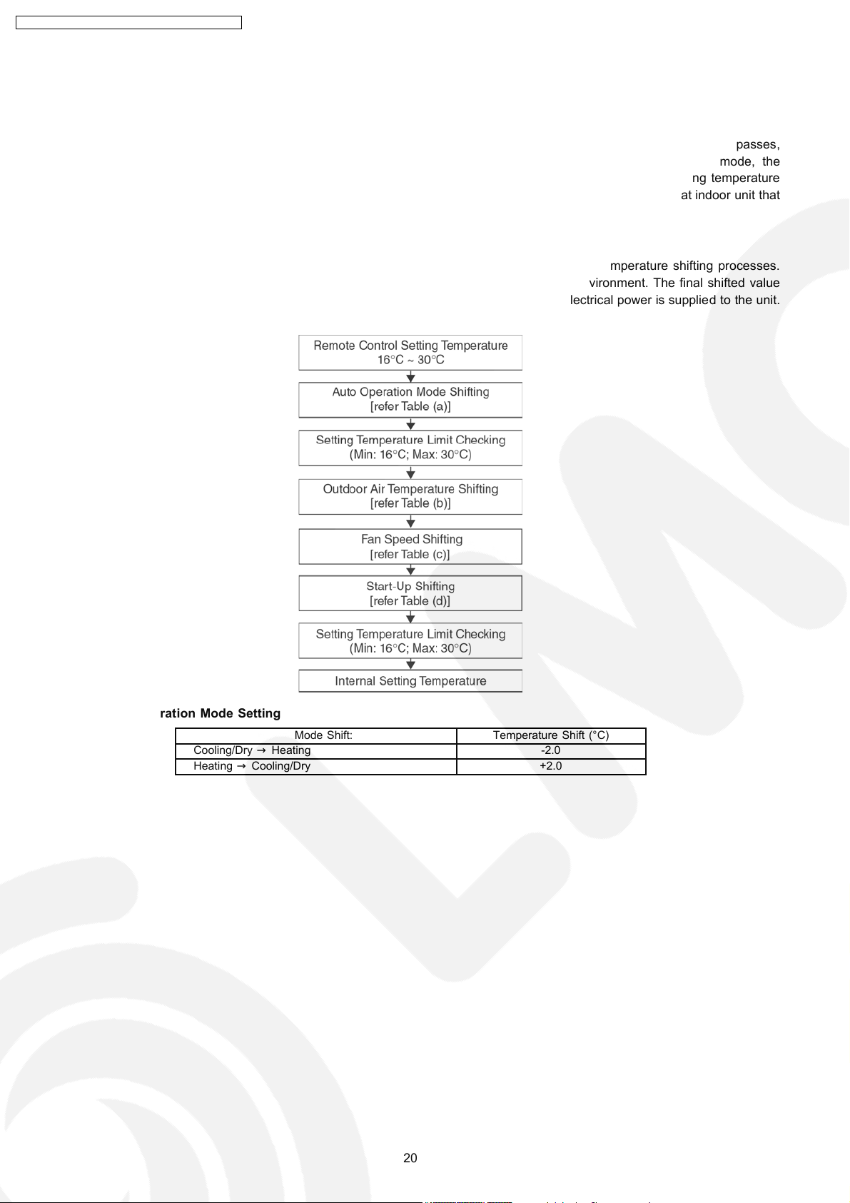
9.1.1. Internal Setting Temperature
Once the operation starts, remote control setting temperature will be taken as base value for temperature shifting processes.
These shifting processes are depending on the air conditio ner settings and the operation environment. The final shifted value
will be used as internal setting temperature and it is updated continuously whenever the electrical power is supplied to the unit.
Table (a): Auto Operation Mode Setting
Cooling/Dry→Heating -2.0
Heating→Cooling/Dry +2.0
Mode Shift: Temperature Shift (°C)
20
Page 21
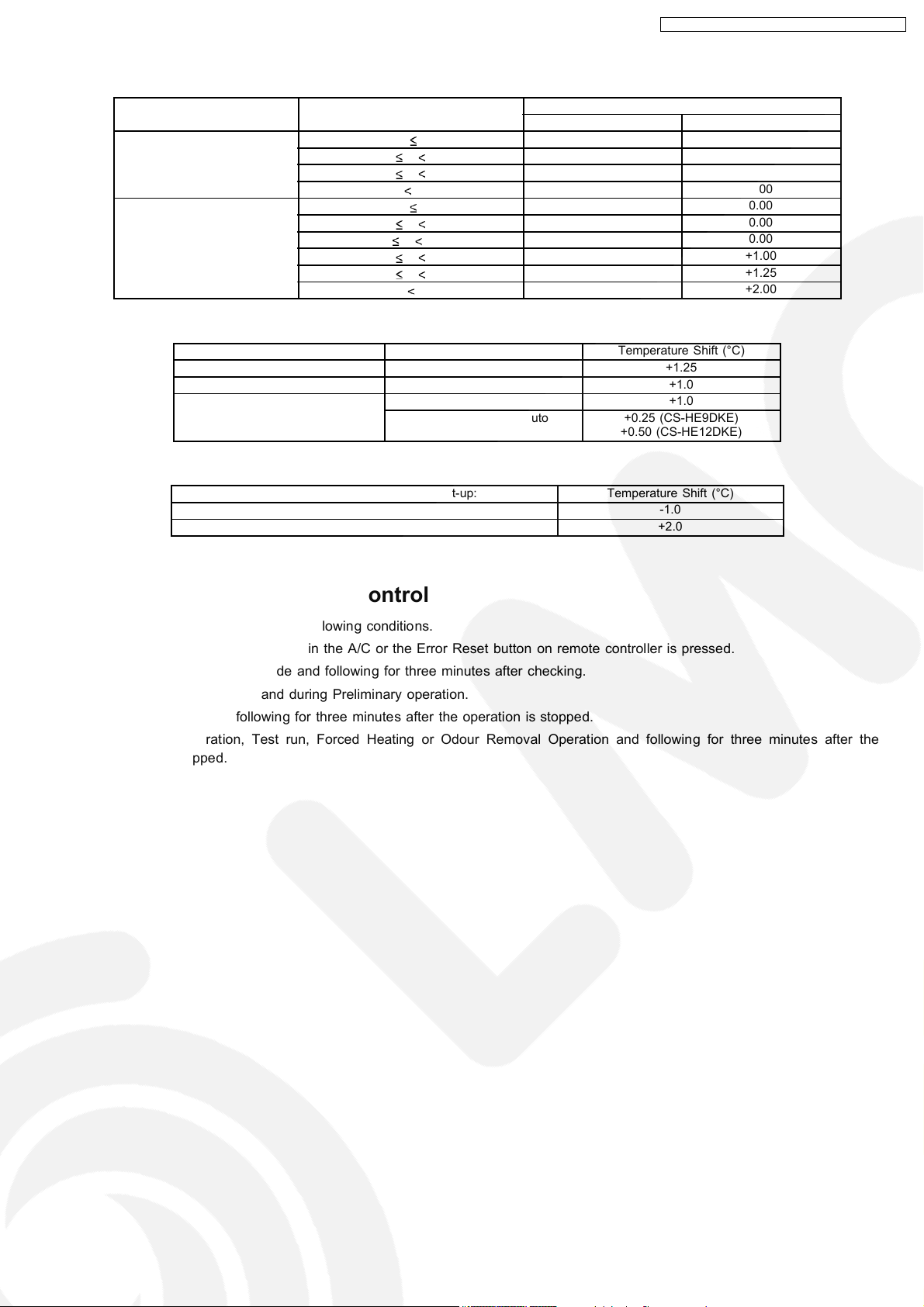
Table (b): Outdoor Air Temperature Shifting
Mode: Outdoor Temperature, X (°C): Temperature Shift (°C)
Cooling/Soft Dry 38 X 0.00 0.00
Heating 21 X 0.00 0.00
Table (c): Fan Speed Shifting
Mode: Fan Speed: Temperature Shift (°C)
Cooling All +1.25
Soft Dry All +1.0
Heating Lo +1.0
Table (d): Start-Up Shifting
Mode within 60 Minutes from Start-up: Temperature Shift (°C)
Cooling/Soft Dry -1.0
Heating +2.0
CS-HE9DKE CU-HE9DKE / CS-HE 12DKE CU-HE12DKE
CS-HE9DKE CS-HE12DKE
30 X 38 0.00 0.00
23 X 30 0.00 0.00
X 23 0.00 0.00
17 X 21 0.00 0.00
9 X 17 0.00 0.00
5 X 9 +0.50 +1.00
1 X 5 +1.00 +1.25
X 1 +1.50 +2.00
Hi, Me-, Me, Me+, Auto +0.25 (CS-HE9DKE)
+0.50 (CS-HE12DKE)
9.2. Indoor Power Relay Control
The Power Relay turns on under the following conditions.
1. For three minutes, when plugged in the A/C or the Error Reset button on remote controller is pressed.
2. During Installation Check Mode and following for three minutes after checking.
3. During On-timer sampling and during Preliminary operation.
4. During Operation and following for three minutes after the operation is stopped.
5. During Auto Operation, Test run, Forced Heating or Odour Removal Operation and following for three minutes after the
operation is stopped.
21
Page 22
CS-HE9DKE CU-HE9DKE / CS-HE 12DKE CU-HE12DKE
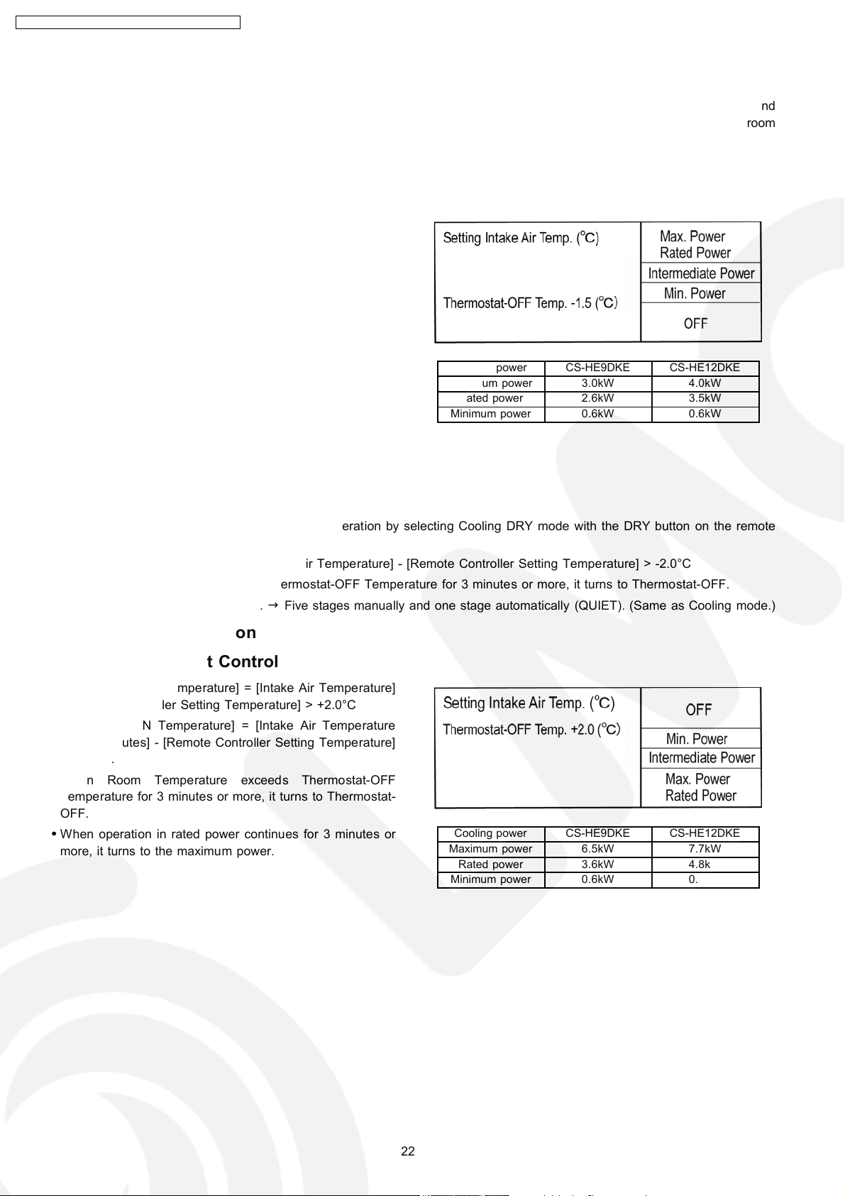
9.3. Room Temperature Control (Compressor Control)
Operating frequency of a compressor is decided according to temperature differen ces between remote controller setting and
room temperatures. By adding a relative method, based on current frequency, which gives frequency changes, a room
temperature is adjusted.
9.3.1. Cooling Operation
9.3.1.1. Thermostat Control
•
•
[Thermostat-ON Tempe rature] = [Intake Air Temperature] -
• •
[Remote Controller Setting Tempe rature] < -1.5°C
•
•
[Thermostat-ON Temperature] = [Intake Air Temperature
• •
after 2 minutes] - [Remote Controller Setting Temperature]
< -1.5°C
•
•
When Room Temperature is below Thermostat-OFF
• •
Temperature for 3 minutes or more, it turns to ThermostatOFF.
•
•
The maximum power is applied only for the first 30 minutes
• •
of the operation, after that, rated power is applied. If the
POWERFUL Switch is pressed during operation, the
maximum power will be applied for 30 minutes.
Cooling power CS-HE9DKE CS-HE12DKE
Maximum power 3.0kW 4.0kW
Rated power 2.6kW 3.5kW
Minimum power 0.6kW 0.6kW
9.3.2. Dry Operation
9.3.2.1. Thermostat Control
•
•
The unit can be operated in the Scrolling Dry Operation by selecting Cooling DRY mode with the DRY button on the remote
• •
controller.
•
•
[Thermostat-OFF Temperature] = [Intake Air Temperature] - [Remote Controller Setting Temperature] > -2.0°C
• •
•
•
When Room Temperature exceeds Thermostat-OFF Temperature for 3 minutes or more, it turns to Thermostat-OFF.
• •
•
•
The fan speed setting is selectable.→Five stages manually and one stage automatically (QUIET). (Same as Cooling mode.)
• •
9.3.3. Heating Operation
9.3.3.1. Thermostat Control
•
•
[Thermostat-OFF Temperature] = [Intake Air Temperature]
• •
- [Remote Controller Setting Temperature] > +2.0°C
•
•
[Thermostat-ON Temperature] = [Intake Air Temperature
• •
after 2 minutes] - [Remote Controller Setting Temperature]
< +2.0°C.
•
•
When Room Temperature exceeds Thermostat-OFF
• •
Temperature for 3 minutes or more, it turns to Thermostat-
OFF.
•
•
When operation in rated power continues for 3 minutes or
• •
more, it turns to the maximum power.
Cooling power CS-HE9DKE CS-HE12DKE
Maximum power 6.5kW 7.7kW
Rated power 3.6kW 4.8kW
Minimum power 0.6kW 0.6kW
22
Page 23
CS-HE9DKE CU-HE9DKE / CS-HE 12DKE CU-HE12DKE
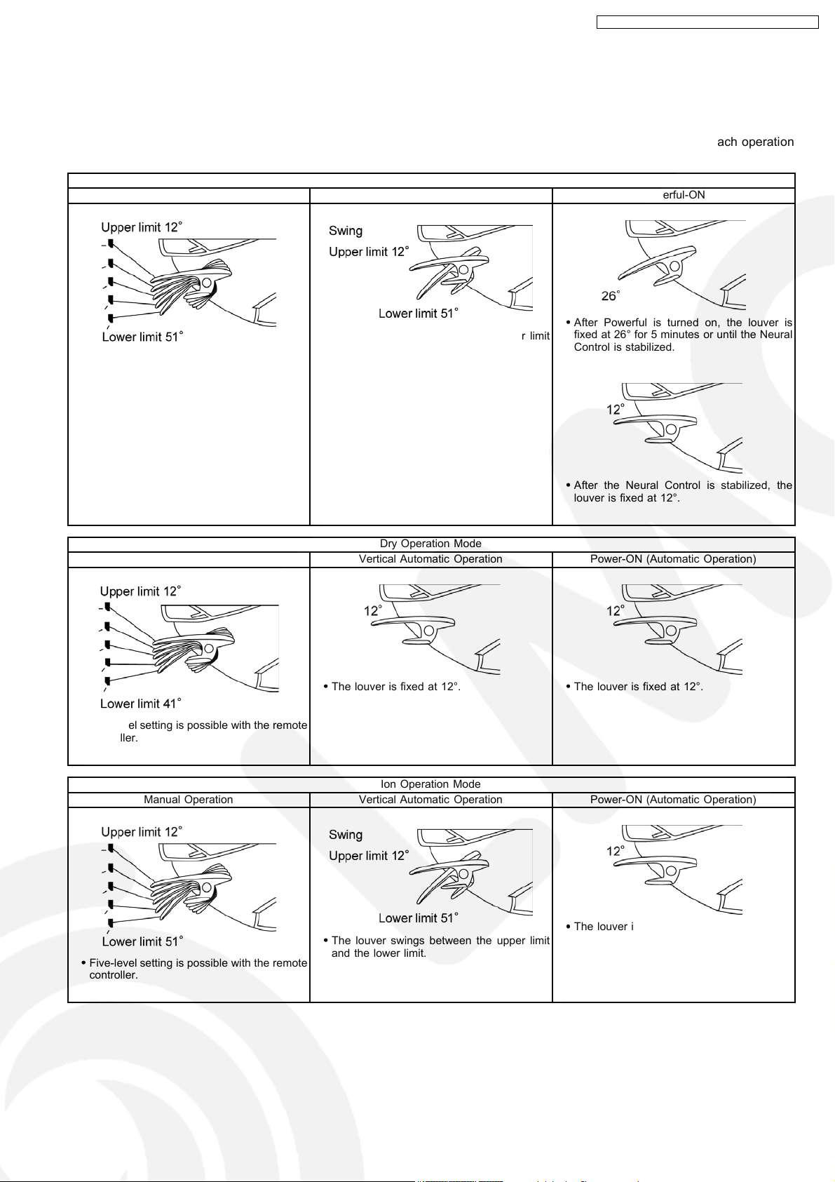
9.4. Airflow Direction Control
9.4.1. Horizontal and Vertical Directions
Vertical louver is controlled by remote control: the Vertical Airflow Direction button on the remote controller and by each operation
mode, as shown in the table below.
Cooling Operation Mode
Manual Operation Vertical Automatic Operation Powerful-ON
•
•
After Powerful is turned on, the louver is
• •
fixed at 26° for 5 minutes or until the Neural
Control is stabilized.
•
•
Five-level setting is possible with the remote
• •
controller.
•
•
The louver swings between the upper limit
• •
and the lower limit.
Manual Operation Vertical Automatic Operation Power-ON (Automatic Operation)
•
•
Five-level setting is possible with the remote
• •
controller.
Manual Operation Vertical Automatic Operation Power-ON (Automatic Operation)
Dry Operation Mode
•
•
The louver is fixed at 12°.
• •
Ion Operation Mode
•
•
After the Neural Control is stabilized, the
• •
louver is fixed at 12°.
•
•
The louver is fixed at 12°.
• •
•
•
Five-level setting is possible with the remote
• •
controller.
•
•
The louver swings between the upper limit
• •
and the lower limit.
23
•
•
The louver is fixed at 12°.
• •
Page 24
CS-HE9DKE CU-HE9DKE / CS-HE 12DKE CU-HE12DKE
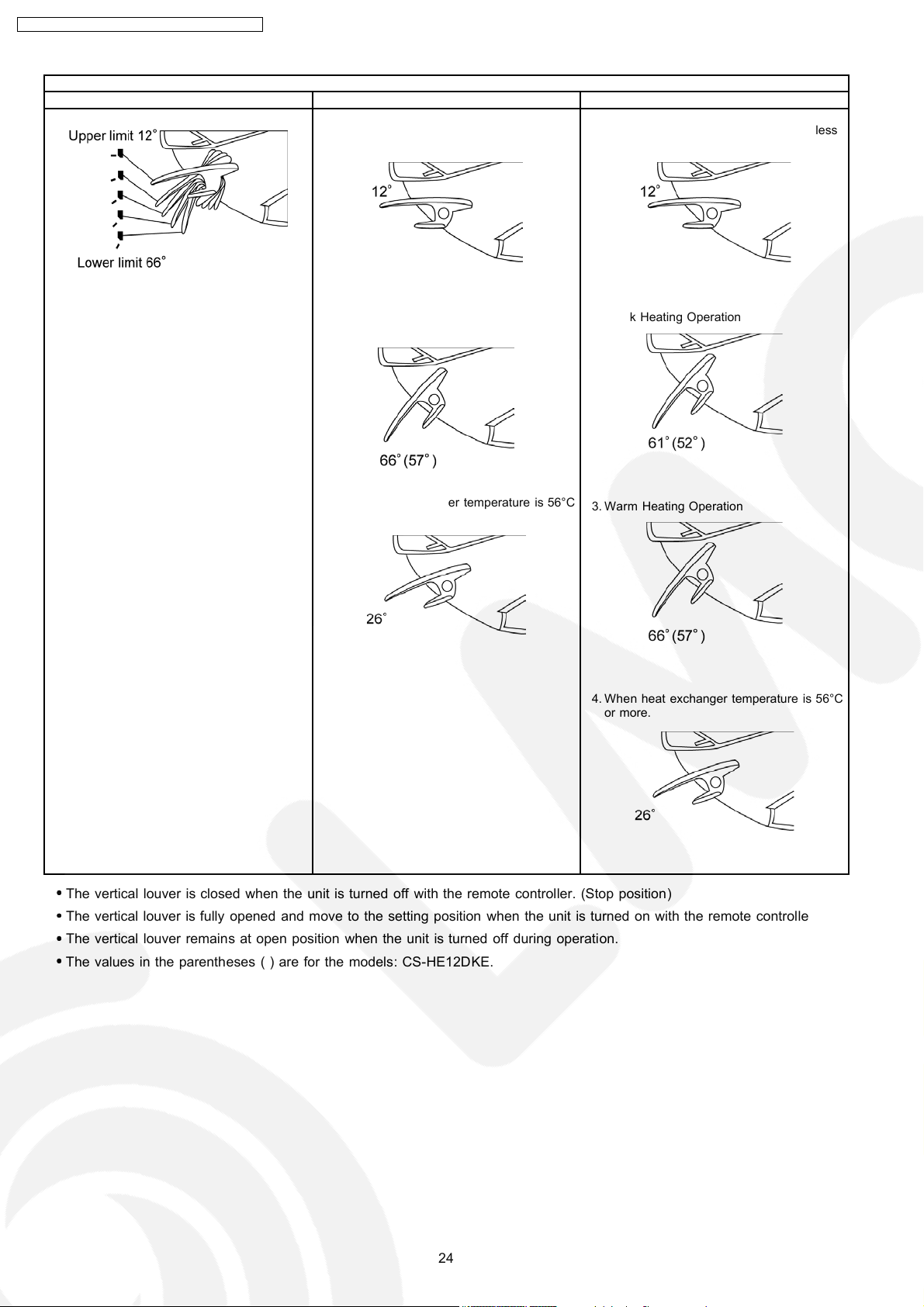
Manual Operation Vertical Automatic Operation Powerful-ON
Heating Operation Mode
•
•
Five-level setting is possible with the remote
• •
controller.
1. When heat exchanger temperature is less
than 32°C.
2. When heat exchanger temperature is
between 32°C and 56°C.
3. When heat exchanger temperature is 56°C
or more.
1. When heat exchanger temperature is less
than 32°C.
2. Quick Heating Operation
3. Warm Heating Operation
4. When heat exchanger temperature is 56°C
or more.
•
•
The vertical louver is closed when the unit is turned off with the remote controller. (Stop position)
• •
•
•
The vertical louver is fully opened and move to the setting position when the unit is turned on with the remote controller.
• •
•
•
The vertical louver remains at open position when the unit is turned off during operation.
• •
•
•
The values in the parentheses ( ) are for the models: CS-HE12DKE.
• •
24
Page 25

9.4.2. Horizontal Airflow Direction Control
CS-HE9DKE CU-HE9DKE / CS-HE 12DKE CU-HE12DKE
Operation
Mode
Cooling
Dry
Ion
Horizontal Automatic Operation Operation for 5 min. after Powerful-ON or
•
•
The louver horizontally swings at a fixed
• •
cycle.
Horizontal Automatic Operation Operation for 5 min. after Powerful-ON
•
•
The louver horizontally swings at a fixed
• •
cycle.
Horizontal Automatic Operation Operation after Powerful-ON
the Neural Control is stabilized.
•
•
The louver horizontally swings at a fixed
• •
cycle.
Heating When heat exchanger
temperature is below 32°C.
When heat exchanger is
between 32°C (, incl.) and 56°C
(, excl.)
•
•
The louver horizontally swings at a fixed
• •
cycle.
Horizontal Automatic Operation Operation after Powerful-ON
When the Neural Control is stabilized.
•
•
The louver horizontally swings at a fixed
• •
cycle.
When the Neural Control is not stabilized. In Warm Heating Operation
•
•
The louver horizontally swings at a fixed
• •
cycle.
In Quick Warm Operation
When heat exchanger
temperature is 56°C or more.
25
Page 26

CS-HE9DKE CU-HE9DKE / CS-HE 12DKE CU-HE12DKE
9.5. Quiet operation (Cooling Mode / Cooling area of Dry Mode)
A. Purpose
To provide quiet cooling operation at limited fan speed which lower than Manua l Low Fan Speed. (See 9.6 Fan Motor Operation
table.)
•
•
It improves the operation noise approximately 3dB compared to Manual Low Fan Speed.
• •
B. Control condition
a. Quiet operation start condition
•
•
When QUIET button at remote control is pressed.
• •
(QUIET is approved on LED at remote control.)
b. Quiet operation stop condition
•
•
One of the following conditions is satisfied, QUIET operation is to be concealed.
• •
1. Repressing QUIET button during quiet operation.
2. Pressing POWERFUL button.
3. Pressing FAN SPEED button, the operation is to be shifted to the selected fan speed.
4. Changing the operation mode to IONIZER only operation.
5. Stopping the operation by OFF/ON button and/or OFF Timer.
9.5.1. Quiet operation under Dry operation (Dry area at Dry Mode)
Automatic Fan Speed (Dry operation)
Manual Fan Speed (Dry operation)
26
Page 27

CS-HE9DKE CU-HE9DKE / CS-HE 12DKE CU-HE12DKE
9.5.2. Quiet operation (Heating)
A. Purpose
To provide quiet heating operation at limited fan speed which lower than Manual Low Fan Speed. (See 9.6 Fan Motor Operation
table.)
•
•
It improves the operation noise approximately 3dB compared to Manual Low Fan Speed.
• •
B. Control condition
a. Quiet operation start condition
•
•
When QUIET button at remote control is pressed.
• •
(QUIET is approved on LED at remote control.)
b. Quiet operation stop condition
•
•
One of the following conditions is satisfied, QUIET operation is to be concealed.
• •
1. Repressing QUIET button during quiet operation.
2. Pressing POWERFUL button.
3. Pressing FAN SPEED button, the operation is to be shifted to the selected fan speed.
4. Changing the operation mode to IONIZER only operation.
5. Stopping the operation by OFF/ON button and/or OFF Timer.
27
Page 28

CS-HE9DKE CU-HE9DKE / CS-HE 12DKE CU-HE12DKE
9.6. Indoor Fan Control
9.6.1. Fan Motor Operation
•
•
Fan speed is controlled according to operation conditions such as fan speed setting on the remote controller as shown in the
• •
table below.
•
•
There is a different speed control from setting on the remote controller.
• •
•
•
When Dry operation is selected, in the Cooling area, fan speed will be switched to one at Cooling mode and in the Dry area,
• •
it will be switched to one at Dry mode.
CS-HE9DKE
CS-HE12DKE
28
Page 29

CS-HE9DKE CU-HE9DKE / CS-HE 12DKE CU-HE12DKE
9.6.2. Cooling Operation
1. Automatic Fan Speed
Odour Cut Control makes fan stop temporarily for 40 seconds at the beginning of unit operation or Thermostat-ON in order to
wash away odour ingredients from heat exchanger with dehumidifying water. Fan operation is repeated every 20 seconds at a
speed of "SLo" (Refer to the “Indoor Fan Control” chapter.) as the graph shown below.
2. Powerful
Unit is automatically operated in Quick Cooling (Fan speed "SHi": Refer to the "Indoor Fan Control” chapter.) in the initial 5
minutes of the operation and after that, switched to Chilly Cooling according to the symmetrical areas.
3. Low noise control
At setting of Fan Speed: "AUTO" (Refer to the “Indoor Fan Control” chapter.), if room temperature reaches a setting
temperature, fan speed will be reduced for the fan noise reduction.
4. Dew Condensation Prevention Control
The maximum frequency for Indoor Unit is decided by the Dew Condensation Prevention Control according to elapsed
operating times. Condition: Indoor unit fan speed is "Me-" or less.
CS-HE9DKE CS-HE12DKE
Max. Frequency (A) (Hz) 35 54
Max. Frequency (B) (Hz) 35 42
Max. Frequency (C) (Hz) 30 37
•
•
Conditions resolutive
• •
−
−
When remote controller setting temperature or fan speed setting is changed:
− −
−
−
When 420 minutes elapsed:
− −
5. Forced Cooling Operation
Fan speed will be “Hi” (Refer to the “Indoor Fan Control” chapter.) when the units is operated at Forced operation mode.
9.6.3. Dry Operation
In the cooling mode area, fan speed is the same as cooling operation mode. In the dry mode area, it is switched to "SLo". (Refer
to the “Indoor Fan Control” chapter.) In the Thermostat-OFF, fan stops 5.5 minutes and after that, operates at a speed of "SLo"
(Refer to the “Indoor Fan Control” chapter.). (At manual fan speed) At automatic fan speed operation, fan operates repeatedly
between 90-second stop and 20-second "SLo". At the beginning of unit operation and Thermostat-ON, fan stops 40 seconds.
9.6.4. Heating Operation
1. Hot Start and Cold Draft
At the beginning of unit operation, when indoor heat exchanger temperature is low, fan will be stopped. When the temperature
is getting high, the unit will be prevented from Cold Draft by increasing fan speed.
2. Automatic fan speed
At automatic fan speed setting, when the heat exchanger temperature is getting high, the unit will be prevented from Cold draft
by increasing fan speed as well as manual fan speed setting. In a fixed fan speed area, fan speed will be controlled to discharge
29
Page 30

CS-HE9DKE CU-HE9DKE / CS-HE 12DKE CU-HE12DKE
air having a constant temperature.
•
•
Refer to the “Indoor Fan Control” chapter for fan speed of each model.
• •
3. Thermostat-OFF
In thermostat-OFF, fan will operate repeatedly between the speeds of “SLo” for 20 second and “SSLo” for 100 seconds. (Refer
to the “Indoor Fan Control” chapter.)
4. Forced Heating Operation
In Forced Heating mode operation, fan speed is “Hi”. (Refer to the “Indoor Fan Control” chapter.)
9.7. Powerful Operation
If the POWERFUL button is pressed during operating in Cooling, Heating, Dry or AUTO, the unit always forces to operate in
respective modes (Quick Cooling, Quick Heating and Dry) for 5 minutes, which fan speed is "SHi" even though unit is in each
stable area.
9.7.1. Cooling Operation
•
•
Airflow direction, Fan speed and Setting temperature are
• •
optimized.
•
•
“[Intake Air temperature] - [Remote controller setting
• •
temperature]” is detected every 30 seconds by indication
from indoor unit and controlled to each area.
Quick Cooling→Unit forcibly turns to Quick Cooling operation
for 5 minutes after Powerful-ON even through it is in the Chilly
Cooling area.Chilly Cooling→Discharge air temperature is
kept low by changing fan speed according to room temperature
and chilly feeling will be produced.
9.7.2. Dry Operation
•
•
Airflow direction, Fan speed and Setting temperature are
• •
optimized.
•
•
“[Intake air temperature] - [Remote controller setting
• •
temperature]” is detected every 30 seconds by indication
from indoor unit and controlled to each area.
Quick Cooling→Unit forcibly turns to Quick Cooling operation
for 5 minutes after powerful-ON even through it is in the Chilly
Air Cooling area.Chilly Cooling→Discharge air temperature is
kept low by changing fan speed according to room temperature
and chilly feeling will be produced.
30
Page 31

CS-HE9DKE CU-HE9DKE / CS-HE 12DKE CU-HE12DKE
9.7.3. Heating Operation
•
•
Airflow direction, Fan speed and Setting temperature are
• •
optimized.
•
•
“[Intake Air temperature] - [Remote controller setting
• •
temperature]” is detected every 30 seconds by indication
from indoor unit and controlled to each area.
Quick Heating→Unit forcibly turns to Quick Heating operation
for 5 minutes after Powerful-ON even through it is in the Warm
Heating area.Warm Heating→Discharge air temperature is
kept high by changing fan speed according to room
temperature and warm feeling will be produced.
9.8. Automatic Operation
•
•
Operation mode (Cooling, Dry and Heating) is automatically selected.
• •
•
•
Operation mode is selected at the beginning of unit operation and every 30 minutes. Temperature, fan speed and airflow
• •
direction are set with the remote controller.
•
•
During cooling mode operation, if Dry mode is selected in next operation mode selection, the operation will be Cooling Dry.
• •
9.8.1. Operation Mode Selection
Operation mode is selected according to outdoor air temperature, intake air temperature and setting temperature.
1. "Heating" is selected when outdoor air temperature is below 16°C.
2. "Cooling" is selected when intake air temperature is 25°C or more. (But, when intake air temperature is 16°C or more.)
3. When outdoor air temperature is below 25°C, if remote controller setting temperature is increased, selectable range of
“Heating”, if decreased, selectable range of “Heating” will be extended respectively.
31
Page 32

CS-HE9DKE CU-HE9DKE / CS-HE 12DKE CU-HE12DKE
9.9. Sleep Timer Operation
•
•
Sleep timer setting with the remote controller makes the unit automatically turn off on the off-set times (0.5, 1, 2, 3, 5 and 7
• •
hours). Remained time shows every one hour on a display of the remote controller. Remained time disappears when time is up.
•
•
In 5- and 7-hour sleep timer settings, “Sleep Shift Control" functions in and after 3 hours.
• •
•
•
Sleep Shift Control in Cooling Operation
• •
−
−
Indoor fan speed is set to "Lo". (Refer to the “Indoor Fan Control” chapter for each model.)
− −
−
−
A setting temperature is increased by 1°C.
− −
•
•
Sleep Shift Control in Dry Operation
• •
−
−
Indoor fan speed is set to "SLo". (Refer to the “Indoor Fan Control” chapter for each model.)
− −
−
−
A setting temperature is increased by 1°C.
− −
•
•
Sleep Shift Control in Heating Operation
• •
−
−
Indoor fan speed is set to "Lo-". (Refer to the “Indoor Fan Control” chapter for each model.)
− −
−
−
A setting temperature is decreased by 1°C.
− −
9.10. Timer Operation
On Timer
•
•
According to air-conditio ning load, preliminary operation
• •
is performed to be a set temperature on set time.
Preliminary operation time is as shown in the table on
the right.
•
•
Indoor and outdoor fans operate for 30 seconds in 70
• •
minutes before a set time, and outdoor and intake air
temperatures are detected.
•
•
Airflow direction in preliminary operation is followed by
• •
remote controller setting. (Same condition as in normal
operation.) Fan speed in preliminary operation is as
shown in the table on the right.
•
•
In preliminary operation, deicing judgment is performed
• •
after heating operated for 15 minutes in 50 minutes
before set ON-time. This is because it makes start-up
time short when outdoor air temperature is extremely
low in midwinter.
Preliminary operation in Cooling or Dry operation
Outdoor Air
Temperature
35°C or more — Before 15 min.
— 35°C or more Before 15 min.
30 - 35°C 25 - 30°C Before 10 min.
Below 30°C Below 25°C Before 5 min.
Preliminary operation in Heating operation
Outdoor Air
Temperature
5°C or more — Before 40 min.
— 15 °C or more Before 40 min.
0 - 5°C 5 - 15°C Before 45 min.
Below 0°C Below 5°C Before 50 min.
Fan speed in Preliminary operation
Operation mode Cooling, Cooling
Manual speed Selected fan
Automatic speed Up to Lo Up to Lo
Intake Air
Temperature
Intake Air
Temperature
Dry
speed
Preliminary Operation
Starting Time
Preliminary Operation
Starting Time
Heating
Selected fan speed
9.11. Auto Restart Control
1. When the power supply is cut off during the operation of air conditioner, the compressor will re-operate within three to four
minutes (there are 10 patterns between 2 minutes 58 seconds and 3 minutes 52 seconds to be selected randomly) after power
supply resumes.
2. This type of control is not applicable during ON/OFF Timer setting.
32
Page 33

CS-HE9DKE CU-HE9DKE / CS-HE 12DKE CU-HE12DKE
9.12. Ionizer Operation
Single Ionizer Operation
•
•
The unit turns to single Ionizer operation mode by pressing the ION button on the remote controller at stop mode and the
• •
ION LED (Green) on the main unit will light up.
* Temperature setting is not possible during the operation.
Simultaneous Ionizer Operation (Heating, Cooling, Dry and Auto)
•
•
The unit turns simultaneous Ionizer operation mode by pressing the ION button on the remote controller at each
• •
operation mode (Heating, Cooling, Dry and Auto) and the ION LED (Green) on the main unit will light up. The LED will
be off by pressing the button again, but the unit remains the operation.
* To stop all the operations, press the OFF/ON button on the remote controller.
Single blinking of the ION LED does not indicate Breakdown.
When unit was operated under the conditio n that a discharge insulation of the Ion generator is deteriorated (Dust, Attached
water, etc.):
If the insulation deterioration of the unit discharge part is big;
Insulation deterioration will be detected in and after 2 seconds from the unit operation starting, and the unit will turn off for 30
minutes and turn on again. When this operation is repeated 24 times, the ION LED will start blinking. But, if the unit operation
is stopped or the Ionizer is operated properly for 10 minutes, the count will be cleared.
Condition resolutive
It can be canceled by stopping the operation during the ION LED blinking.
33
Page 34

CS-HE9DKE CU-HE9DKE / CS-HE 12DKE CU-HE12DKE
9.13. Oxygen Enrich Operation
9.13.1. Oxygen Enrich System Figure
9.13.2. Indoor Fan Control
Single Oxygen Enrich operation
1. Manual fan speed ............. Not available for the remote controller.
2. Automatic fan speed ............. Fixed.
Revolution (rpm)
Normal Fan Speed (AUTO) 480
•
•
When used in common with other modes, it will be followed by other modes.
• •
Order of priority: Cooling , Dry and Heating > Ion > Oxygen Enrich
•
•
Powerful and Quiet operations are not accepted at the Oxygen Enrich Operation mode.
• •
9.13.3. Indoor Airflow Direction Control
1. Manual and Automatic Airflow Direction ................. Same as Cooling operation.
•
•
When used in common with other modes, it will be followed by other modes.
• •
Order of priority: Cooling , Dry and Heating > Ion > Oxygen Enrich
9.13.4. Conditions of starting and cancellation
1. ON/OFF by the "Oxygen & Ventilation Selection" Switch on the remote controller
•
•
When "Oxygen" is selected with the Switch under a condition of Ionizing Air Clearing OFF
• •
→
Single Oxygen Enrich Operation
•
•
When "Oxygen" is selected with the Switch under a condition of Ionizing Air Clearing ON,
• •
→
Ionizing Air Cleaning + Simultaneous Oxygen Enrich Operation
•
•
When "Oxygen" is selected with the Switch during Single Oxygen Enrich Operation,
• •
→
Operation is stopped.
•
•
When "Oxygen" is selected with the Switch during Cooling, Heating, Dry or Ionizing Air Cleaning Operation,
• •
→
Cooling, Heating, Dry or Ionizing Air Cleaning Operation + Simultaneous Oxygen Enrich Operation,
•
•
When "Oxygen" is selected with the Switch during Cooling , Heating, Dry or Ionizing Air Cleaning Operation + Simultaneous
• •
Oxygen Enrich Operation,
34
Page 35

CS-HE9DKE CU-HE9DKE / CS-HE 12DKE CU-HE12DKE
→
Cooling, Heating, Dry or Ionizing Air Cleaning Operation
•
•
When "Oxygen" is selected with the Switch during Ionizing Air Cleaning Operation + Simultaneous Oxygen Enrich
• •
Operation,
→
Ionizing Air Cleaning Operation
2. Common use with ON/OFF Timer
•
•
When ON-Time of the Timer setting is up during operation stop,
• •
→
In last time operation, if unit is stopped in Single Oxygen Enrich Operation, it operates in Single Oxygen Enrich mode.
In last time operation, if unit is stopped in operations other than Single Oxygen Enrich, it operates at its operation mode.
•
•
When ON-Time of the Timer setting is up during Oxygen Enrich Operation,
• •
→
Unit remains the operation.
•
•
When OFF-Time of the Timer setting is up during Oxygen Enrich Operation,
• •
→
Unit stops operating.
•
•
Preliminary Operation of Single Oxygen Enrich Operation
• •
→
Not applica ble.
9.13.5. Oxygen Monitor Display
Monitor level 0 1 2 3
Status Stop Stop (Vacuum pump
LED Display OFF Blinking — ON
Oxygen requirement level 0 0 — 3
•
•
Monitor level when installation (Oxygen) is checked is "3".
• •
operation)
— In operation
→
9.13.6. Oxygen Enrich Control
•
•
Vacuum pump is operated after Oxygen requirement level that is decided in outdoor unit from Oxygen supply level decided in
• •
indoor unit and protective control devices such as a vacuum pump.
Oxygen Requirement
Level
0 0 10 0
— 1 7 3
— 2 4 6
3 3 0 10
•
•
Operating cycle period of Vacuum pump: 10 minutes; Oxygen supply level is renewed in a cycle.
• •
Oxygen Supply Level Vacuum pump operation time
OFF-time (min.) ON-time (min.)
35
Page 36

CS-HE9DKE CU-HE9DKE / CS-HE 12DKE CU-HE12DKE
9.13.7. Installation (Oxygen) Check Control
•
•
For operation check at installation and breakdown self-
• •
diagnosis, continuous operation of 2-way valve and vacuum
pump is conducted by checking installation from indoor
room.
9.14. Deice Control <Heating>
•
•
Degree of frosting is expected by operation time, heat
• •
exchanger temperature and outdoor air temperature.
•
•
According to frosting conditions, deicing operation is
• •
effectively performed.
1. Timer for deice control will function when outdoor heat
exchanger temperature after continuous 40 minutes heating
operation is below the primary judgment temperature.
When the timer reaches 20 minutes or heat exchan ger
temperature is below the secondary judgment temperature,
deicing operation will start.
2. Four-way valve is switched and deicing is performed by
cooling cycle.
3. Deicing will be stopped when 12 minutes elapsed from
starting of the operation or heat exchanger temperature
reaches 17°C or more.
36
Page 37

CS-HE9DKE CU-HE9DKE / CS-HE 12DKE CU-HE12DKE
9.15. Protection Control
9.15.1. Time Delay Safety Control
•
•
Compressor will not start for two minutes after stop of the operation.
• •
9.15.2. 30 Seconds Forced Operation
•
•
Once compressor starts the operation, it will not stop its operation for 30 seconds. However, it can be stopped with the remote
• •
controller or the Auto button on the indoor unit.
9.15.3. Total Running Current Control
1. When the total running current exceeds I1, compressor operation frequency is reduced. If it reaches below I1, the operation
frequency is increased. (But, up to programmed frequency.)
2. If total running current exceeds I2, compressor is stopped immediately.
3. If it happens three (3) times within 20 minutes, operation will be stopped and Timer LED blinks. (“F98” is activating.)
Running current CS-HE9DKE CS-HE12DKE
Cooling I1 4.5A 5.8A
I2 12.5A 12.5A
Heating I1 7.2A 9.6A
I2 12.5A 12.5A
9.15.4. IPM (Power transistor) Protection Control (DC Peak detection)
Abnormal Current Control
•
•
If inverter load current (DC peak) exceeds a rated value, compressor will be stopped immediately. When the excess
• •
occurs within 30 seconds after operation, it restarts in 1 minute and when after 30 seconds, restarts in 2 minutes.
•
•
If the excess continuously occurs 7 times within 30 minutes after compressor starts, the unit will be stopped and timer
• •
lamp on the indoor unit will be blinking. (“F99” is to be confirmed.)
IPM Overheating Prevention Control
•
•
If temperature of IPM exceeds 103°C, compressor will be stopped. It will restart in 2 minutes. Temperature for restarting:
• •
90°C.
•
•
If the excess occurs 4 times within 30 minutes after compressor starts, the compressor will be stopped and timer lamp
• •
on the indoor unit will be blinking. (“F96” is to be confirmed.)
9.15.5. Compressor Overheating Prevention Control
1. If discharge pipe temperature exceeds 100°C, compressor power will be limited.
2. If discharge pipe temperature exceeds 112°C, compressor will be stopped.
3. If the above excess occurs 4 times per 10 minutes, timer lamp will be blinking. (“F97” is to be confirmed.)
9.15.6. Outdoor High Pressure Prevention Control (Cooling and Dry operations)
1. If outdoor heat exchanger temperature exceed s 63°C in cooling or dry operation, compressor will be stopped.
2. Timer lamp is not blinking. (“F95” is memorized, then.)
9.15.7. Compressor Protection Control (Refrigeration Cycle Abnormality)
In Cooling and Dry operations
1. When compressor is operated continuously for 5 minutes in the maximum cooling power: a running current of 0.6 - 1.2A
(excl.) and “[Indoor intake air temperature] - [Indoor heat exchanger temperature]” < 4°C, compressor will be stopped.
2. If the above excess occurs twice for 20 minutes, timer lamp is to be blinking. (“F91” is to be confirmed.)
In Heating operation
1. When compressor is operated continuously for 5 minutes in the rated heating power: a running current of 0.6 - 1.2A (excl.)
and “[Indoor heat exchan ger temperature] - [Indoor intake air temperature]” < 5°C, compressor will be stopped.
2. If the above excess occurs twice for 20 minutes, timer lamp is to be blinking. (“F91” is to be confirmed.)
37
Page 38

CS-HE9DKE CU-HE9DKE / CS-HE 12DKE CU-HE12DKE
9.15.8. Four-way valve Operation Detection Control (Switching Abnormality between
Cooling and Heating)
In Cooling operation
1. When indoor heat exchan ger temperature exceeds 45°C in 4 minutes after compressor starts, compressor will be stopped.
2. If the above excess occurs 4 times per 30 minutes, timer lamp is to be blinking. (“F11” is to be confirmed.)
In Heating operation
1. When indoor heat exchanger temperature is below 0°C in 4 minutes after compressor starts, compressor will be stopped.
2. If the above excess occurs 4 times per 30 minutes, timer lamp is to be blinking. (“F11” is to be confirmed.)
9.15.9. Anti-Freezing Control (Cooling and Dry operations)
Limit of Cooling power
1. When temperature of indoor heat exchanger is below 5°C, operating frequency will be decreased.
2. When temperature of indoor heat exchanger exceeds 7°C, operating frequency will be increased. (But, up to programmed
frequency.)
3. When temperature of indoor heat exchanger is below 0°C continuously for 6 minutes, compressor will be stopped.
4. Timer lamp is not blinking. (“F99” is memorized, then.)
Limit of Indoor fan speed
•
•
When temperature of indoor heat exchanger is below 6°C (2°C at Dry) continuously for 6 minutes, indoor fan speed will be
• •
increased by 50 rpm.
9.15.10. Outdoor Air Temperature Control
In Cooling and Dry operations
1. When outdoor air temperature is below 25°C, the maximum power will be limited up to about 80-100% of the rated power.
2. When outdoor air temperature is below 18°C, the maximum power will be limited up to about 50-100% of the rated power.
3. When outdoor air temperature is below 11°C, the maximum power will be limited up to about 26-81% of the rated power.
9.15.11. Indoor Intake Air Temperature Control (Heating operation)
1. When indoor air temperature is 35°C or more, the maximum power will be limited up to the rated power.
2. When fan speed is set at "Lo" and intake air temperature is below 21°C, the maximum power will be limited up to the rated
power.
38
Page 39

10 Operating Instructions
CS-HE9DKE CU-HE9DKE / CS-HE 12DKE CU-HE12DKE
39
Page 40

CS-HE9DKE CU-HE9DKE / CS-HE 12DKE CU-HE12DKE
40
Page 41

CS-HE9DKE CU-HE9DKE / CS-HE 12DKE CU-HE12DKE
41
Page 42

CS-HE9DKE CU-HE9DKE / CS-HE 12DKE CU-HE12DKE
42
Page 43

CS-HE9DKE CU-HE9DKE / CS-HE 12DKE CU-HE12DKE
43
Page 44

CS-HE9DKE CU-HE9DKE / CS-HE 12DKE CU-HE12DKE
44
Page 45

CS-HE9DKE CU-HE9DKE / CS-HE 12DKE CU-HE12DKE
11 Installation Instructions
Required tools for Installation Works
1. Philips screw driver 5. Spanner 9. Gas leak detector 13. Multimeter
2. Level gauge 6. Pipe cutter 10. Measuring tape 14. Torque wrench
3. Electric drill, hole core drill
(ø70 mm)
4. Hexagonal wrench (4 mm) 8. Knife 12. Megameter 16. Gauge manifold
7. Reamer 11. Thermomete r 15. Vacuum pump
11.1. Safety Precautions
•
•
Read the following “SAFETY PRECAUTIONS” carefully before installation.
• •
•
•
Electrical work must be installed by a licensed electrician. Be sure to use the correct rating of the power plug and main circuit
• •
for the model to be installed.
•
•
The caution items stated here must be followed because these important contents are related to safety. The meaning of each
• •
indication used is as below. Incorrect installation due to ignoring of the instruction will cause harm or damage, and the
seriousness is classified by the following indications.
This indication shows the possibility of causing death or serious injury.
18 N.m (1.8 kgf.m)
42 N.m (4.2 kgf.m)
55 N.m (5.5 kgf.m)
This indication shows the possibility of causing injury or damage to properties only.
The items to be followed are classified by the symbols:
Symbol with background white denotes item that is PROHIBITED from doing.
•
•
Carry out test running to confirm that no abnormality occurs after the installation. Then, explain to user the operation, care and
• •
maintenance as stated in instructions. Please remind the customer to keep the operating instructions for future referen ce.
1. Engage dealer or specialist for installation. If installation done by the user is defective, it will cause water leakage, electrical shock or fire.
2. Install according to this installation instruction strictly. If installation is defective, it will cause water leakage, electrical shock or fire.
3. Use the attached accessories parts and specified parts for installation. Otherwise, it will cause the set to fall, water leakage, fire or
electrical shock.
4. Install at a strong and firm location which is able to withstand the set’s weight. If the strength is not enough or installation is not properly
done, the set will drop and cause injury.
5. For electrical work, follow the local national wiring standard, regulation and this installation instruction. An independent circuit and single
outlet must be used. If electrical circuit capacity is not enough or defect found in electrical work, it will cause electrical shock or fire.
6. Use the specified cable (1.5 mm2) and connect tightly for indoor/outdoor connection. Connect tightly and clamp the cable so that no
external force will be acted on the terminal. If connection or fixing is not perfect, it will cause heat-up or fire at the connection.
7. Wire routing must be properly arranged so that control board cover is fixed properly. If control board cover is not fixed perfectly, it will
cause heat-up at connection point of terminal, fire or electrical shock.
8. When carrying out piping connection, take care not to let air substances other than the specified refrigerant go into
refrigeration cycle. Otherwise, it will cause lower capacity, abnormal high pressure in the refrigeration cycle, explosion
and injury.
9. When connecting the piping, do not allow air or any substances other than the specified refrigerant (R410A) to enter the
refrigeration cycle. Otherwise, this may lower the capacity, cause abnormally high pressure in the refrigeration cycle, and
possibly result in explosion and injury.
10.
•
•
When connecting the piping, do not use any existing (R22) pipes and flare nuts. Using such same may cause
• •
abnormally high pressure in the refrigeration cycle (piping), and possible result in explosion and injury. Use only
R410A materials.
•
•
Thickness of copper pipes used with R410A must be more than 0.8 mm. Never use copper pipes thinner than
• •
0.8mm.
•
•
It is desirable that the amount of residual oil is less than 40 mg/10 m.
• •
11. Do not modify the length of the power supply cord or use of the extension cord, and do not share the single outlet with
other electrical appliances. Otherwise, it will cause fire or electrical shock.
45
Page 46

CS-HE9DKE CU-HE9DKE / CS-HE 12DKE CU-HE12DKE
1. The equipment must be earthed and install with earth breaker. It may cause electrical shock if grounding is not perfect.
2. Do not install the unit at place where leakage of flammable gas may occur.
In case gas leaks and accumulates at surrounding of the unit, it may cause fire.
3. Carry out drainage piping as mentioned in installation instructions. If drainage is not perfect, water may enter the room and damage the
furniture.
1. Selection of the installation location.
Select an installation location which is rigid and strong enough to support or hold the unit, and select a location for easy maintenance.
2. Power supply connection to the room air conditioner.
Connect the power supply cord of the room air conditioner to the mains using one of the following method.
Power supply point shall be the place where there is ease for access for the power disconnection in case of emergency.
In some countries, permanent connection of this room air conditioner to the power supply is prohibited.
1. Power supply connection to the receptacle using a power plug.
Use an approved 15A/16A power plug with earth pin for the connection to the socket.
2. Power supply connection to a circuit breaker for the permanent connection. Use an approved 16A circuit breaker for the permanent
connection. It must be a double pole switch with a minimum 3.5 mm contact gap.
3. Do not release refrigerant.
Do not release refrigerant during piping work for installation, reinstallation and during repairing a refrigeration parts.
Take care of the liquid refrigerant, it may cause frostbite.
4. Installation work.
It may need two people to carry out the installation work.
5. Do not install this appliance in a laundry room or other location where water may drip from the ceiling, etc.
46
Page 47

Attached accessories
Applicable piping kit
CZ-3F5, 7BP (HE9DKE)
CZ-4F5, 7, 10BP (HE12DKE)
CS-HE9DKE CU-HE9DKE / CS-HE 12DKE CU-HE12DKE
Indoor/Outdoor Unit Installation Diagram
SELECT THE BEST LOCATION
INDOOR UNIT
•
•
There should not be any heat source or steam near the
• •
unit.
•
•
There should not be any obstacles blocking the air
• •
circulation.
•
•
A place where air circulation in the room is good.
• •
•
•
A place where drainage can be easily done.
• •
•
•
A place where noise prevention is taken into
• •
consideration.
•
•
Do not install the unit near the door way.
• •
•
•
Ensure the spaces indicated by arrows from the wall,
• •
ceiling, fence or other obstacles.
•
•
Recommended installation height for indoor unit shall be
• •
at least 2.5 m.
OUTDOOR UNIT
•
•
If an awning is built over the unit to prevent direct
• •
sunlight or rain, be careful that heat radiation from the
condenser is not obstructed.
•
•
There should not be any animal or plant which could be
• •
affected by hot air discharged.
•
•
Keep the spaces indicated by arrows from wall, ceiling,
• •
fence or other obstacles.
•
•
Do not place any obstacles which may cause a short
• •
circuit of the discharged air.
•
•
If piping length is over the common length, additional
• •
refrigerant should be added as shown in the table.
•
•
This illustration is for explanation purposes only.
• •
The indoor unit will actually face a differen t way.
47
Page 48

CS-HE9DKE CU-HE9DKE / CS-HE 12DKE CU-HE12DKE
11.2. Indoor Unit
11.2.1. Select The Best Location
(Refer to “Select the best location”
section)
11.2.2. How To Fix Installation Plate
The mounting wall is strong and solid enough to prevent it from
the vibration.
11.2.3. To Drill A Hole In The Wall And
Install A Sleeve Of Piping
1. Insert the piping sleeve to the hole.
2. Fix the bushing to the sleeve.
3. Cut the sleeve until it extrudes about 15 mm from the wall.
Caution
When the wall is hollow, please be sure to use the
sleeve for tube ass’y to prevent dangers caused by
mice biting the connecting cable.
4. Finish by sealing the sleeve with putty or caulking
compound at the final stage.
:
For left side piping, piping connection for liquid should be
this line.
For left side piping, piping connection for gas should be
:
about 60 mm from this line.
For left side piping, piping connecting cable should be
:
about 750 mm from this line.
1. Mount the installation plate on the wall with 5 screws or
more.
(If mounting the unit on the concrete wall, conside r using
anchor bolts.)
•
•
Always mount the installation plate horizontally by
• •
aligning the marking-off line with the thread and using a
level gauge.
2. Drill the piping plate hole with ø70 mm hole-core drill.
•
•
The center of the right piping hole is at the intersection
• •
of lines extending vertically from the edge of the
installation plate and horizontally from the sideways
arrow on the installation plate (see figure above.).
•
•
The center of the left piping hole is at the intersection of
• •
lines extending vertically from the downward arrow on
the installation plate and horizontally from the sideways
arrow on the installation plate (see figure above.).
•
•
Drill the piping hole at either the right or the left and the
• •
hole should be slightly slanted to the outdoor side.
48
Page 49

CS-HE9DKE CU-HE9DKE / CS-HE 12DKE CU-HE12DKE
11.2.4. Indoor Unit Installation
For the right rear piping
1.
For the right and right bottom piping
2.
Pull out the piping and drain hose
How to keep the cover
Insert the connecting cable
For the embedded piping
3.
Install the Indoor Unit
Secure the Indoor Unit
49
Page 50

CS-HE9DKE CU-HE9DKE / CS-HE 12DKE CU-HE12DKE
(This can be used for left rear piping & left bottom piping also.)
Exchange the drain hose and the cap.
50
Page 51

11.2.5. Connect The Cable To The Indoor
Unit
1. The inside and outside connecting cable can be connected
without removing the front grille.
2. Connecting cable between indoor unit and outdoor unit
shall be approved polychloroprene sheathed 4 × 1.5 mm
flexible cord, type designation 245 IEC 57 (H05RN-F) or
heavier cord.
•
•
Ensure the color of wires of outdoor unit and the
• •
terminal Nos. are the same to the indoor’s respectively.
•
•
Earth lead wire shall be longer than the other lead wires
• •
as shown in the figure for the electrical safety in case of
the slipping out of the cord from the anchorage.
•
•
Secure the cable onto the control board with the holder
• •
(clamper).
CS-HE9DKE CU-HE9DKE / CS-HE 12DKE CU-HE12DKE
2
AUTO SWITCH OPERATION
The below operations will be performed by pressing the
“AUTO” switch.
•
•
AUTO OPERATION MODE
• •
The Auto operation will be activated immediately once the
Auto Switch is pressed.
•
•
TEST RUN OPERA TION (for PUMP DOWN/SERVICING
• •
PURPOSE)
The Test Run operation will be activated if the Auto Switch
is pressed continuously for more than 5 sec. to below 8 sec.
A “pep” sound will occur at the fifth sec., in order to identify
the starting of Test Run operation.
HOW TO TAKE OUT CORNER PIECE (LEFT UNDER)
HOW TO TAKE OUT FRONT GRILLE
Please follow the steps below to take out front grille if
necessary such as when servicing.
1. Set the vertical airflow direction louver to the horizontal
position.
2. Slide down the two caps on the front grille as shown in the
illustration at the right, and then remove the three mounting
screws.
3. Pull the lower section of the front grille towards you to
remove the front grille.
Caution
When reinstalling the front grille, first set the vertical
airflow direction louver to the horizontal position and
then carry out above steps 2 - 3 in the reverse order.
Please check that the top side of front grille certainly
caught with fixative rib (4 points) of indoor unit.
51
Page 52

CS-HE9DKE CU-HE9DKE / CS-HE 12DKE CU-HE12DKE
11.3. Outdoor Unit
11.3.1. Select The Best Location
(Refer to “Select the best location”
section)
11.3.2. Install The Outdoor Unit
•
•
After selecting the best location, start installation according
• •
to Indoor/Outdoo r Unit Installation Diagram.
1. Fix the unit on concrete or rigid frame firmly and horizontally
by bolt nut. (ø10 mm).
2. When installing at roof, please consider strong wind and
earthquake. Please fasten the installation stand firmly with
bolt or nails.
11.3.3. Connecting The Piping
Connecting The Piping To Indoor Unit
Please make flare after inserting flare nut (locate at joint portion
of tube assembly) onto the copper pipe. (In case of using long
piping)
Connecting The Piping To Outdoor Unit
Decide piping length and then cut by using pipe cutter. Remove
burrs from cut edge. Make flare after inserting the flare nut
(located at valve) onto the copper pipe.
Align center of piping to valves and then tighten with torque
wrench to the specified torque as stated in the table.
Cutting And Flaring The Piping
1. Please cut using pipe cutter and then remove the burrs.
2. Remove the burrs by using reamer. If burrs is not
removed, gas leakage may be caused.
Turn the piping end down to avoid the metal powder
entering the pipe.
3. Please make flare after inserting the flare nut onto the
copper pipes.
Connect the piping
•
•
Align the center of piping and sufficie ntly tighten the flare
• •
nut with fingers.
•
•
Further tighten the flare nut with torque wrench in specified
• •
torque as stated in the table.
11.3.4. Evacuation Of The Equipment (For Europe & Oceania Destination)
WHEN INSTALLING AN AIR CONDITIONER, BE SURE TO EVACUTE THE AIR INSIDE THE INDOOR UNIT AND PIPES in the
following procedure.
52
Page 53

CS-HE9DKE CU-HE9DKE / CS-HE 12DKE CU-HE12DKE
1. Connect a charging hose with a push pin to the Low and High side of a charging set and the service port of the 3-way valve.
•
•
Be sure to connect the end of the charging hose with the push pin to the service port.
• •
2. Connect the center hose of the charging set to a vacuum pump with check valve, or vacuum pump and vacuum pump adaptor.
3. Turn on the power switch of the vacuum pump and make sure that the needle in the gauge moves form 0 cmHg (0 MPa) to -
76cm Hg (-0.1 MPa). Then evacuate the air approximately 15 minutes.
4. Close the Low side valve of the charging set the turn off the vacuum pump. Make sure that the needle in the gauge does not
move after approximately 5 minutes.
Note: BE SURE TO FOLLOW THIS PROCEDURE INORDER TO AVOID REFRIGERANT GAS LEAKA GE.
5. Disconnect the charging hose from vacuum pump and from the service port of the 3-way valve.
6. Tighten the service port caps of the 3-way valve at a torque of 18 N.m with a torque wrench.
7. Remove the valve caps of both of the 3-way valve. Position both of the valves to “OPEN” using a hexagonal wrench (4 mm).
8. Mount valve caps onto the 2-way valve and the 3-way valve.
•
•
Be sure to check for gas leakage.
• •
Caution
•
•
If gauge needle does not move from 0 cmHg (0 MPa) to -76 cmHg (-0.1 MPa), in step 3 above take the following measure:
• •
•
•
If the leak stops when the piping connections are tightened further, continue working form step 3.
• •
•
•
If the leak does not stop when the connections are retightened, repair the location of leak.
• •
•
•
Do not release refrigerant during piping work for installation and reinstallation. Take care of the liquid refrigerant, it may cause
• •
frostbite.
11.3.5. Connect The Cable To The
Outdoor Unit
1. Remove the control board cover from the unit by looseni ng
the screw.
2. Connecting cable between indoor unit and outdoor unit
shall be approved polychloroprene sheathed 4 × 1.5 mm
flexible cord, type designation 245 IEC 57 (H05RN-F) or
heavier cord.
3. Secure the cable onto the control board with the holder
(clamper).
4. Attach the control board cover back to the original position
with the screw.
11.3.6. Pipe Insulation
1. Please carry out insulation at pipe connection portion as
mentioned in Indoor/Outdoor Unit Installation Diagram.
Please wrap the insulated piping end to prevent water from
going inside the piping.
2
2. If drain hose or connecting piping is in the room (where dew
may form), please increase the insulation by using POLY-E
FOAM with thickness 6 mm or above.
FOR 2 SETS IN ONE ROOM
A switching mechanism to prevent errors occurring in the
operation of one of the air conditioners caused by operating the
buttons on the remote controller for the other air conditioner is
provided. This mechanism was set to “A” at the factory.
Set the other air conditio ner and its remote controller to “B”.
•
•
Set the remote controller to “B”.
• •
Open the remote controller’s battery cover, and cut the
jumper using a pair of pliers.
•
•
Set the air conditio ner to “B”.
• •
1. Hold down the air conditioner’s emergency operation
button for at least 11 seconds, and release it after three
beeps are heard.
(Note: One beep is heard after the button has been held
down for 5 seconds, and two beeps are heard after 8
seconds.)
53
Page 54

CS-HE9DKE CU-HE9DKE / CS-HE 12DKE CU-HE12DKE
2. Within the next 5 minutes, point the remote controller at
the air conditioner, and press the ERROR RESET
button on the remote controller. (A beep is heard,
indicating that this signal was received.)
3. When any button on the remote controller which has
been set to “B” is pressed within the next 5 minutes, the
air conditioner will also be set to “B”. (Another beep is
heard, indicating that this signal was received.)
4. Check that the air conditioner which has been set to “B”
can be operated by the remote controller which has
been set to “B”.
DISPOSAL OF OUTDOOR UNIT DRAIN WATER
•
•
If a drain elbow is used, the unit should be placed on a
• •
stand which is taller than 3 cm.
•
•
If the unit is used in an area where temperature falls below
• •
0°C for 2 or 3 days in succession, it is recommended not to
use a drain elbow, for the drain water freezes and the fan
will not rotate.
EVALUATION OF THE PERFORMANCE
•
•
Operate the unit at cooling operation mode for 15 minutes
• •
or more.
•
•
Measure the temperature of the intake and discharge air.
• •
•
•
Ensure the difference between the intake temperature and
• •
the discharge is more than 8°C.
CHECK ITEMS
Is there any gas leakage at flare nut connection?
Has the heat insulation been carried out at flare nut
connection?
Is the connecting cable being fixed to terminal board firmly?
Is the connecting cable being clamped firmly?
Is the drainage OK?
(Refer to “Check the drainage” section)
Is the earth wire connection properly done?
Is the indoor unit properly hooked to the installation plate?
CHECK THE DRAINAGE
•
•
Open front panel and remove air filters.
• •
(Drainage checking can be carried out without removing the
front grille.)
•
•
Pour a glass of water into the drain tray-styrofoam.
• •
•
•
Ensure that water flows out from drain hose of the indoor
• •
unit.
Is the power supply voltage complied with rated value?
Is there any abnormal sound?
Is the cooling operation normal?
Is the thermostat operation normal?
Is the remote control’s LCD operation normal?
Is the air purifying filter installed?
54
Page 55

CS-HE9DKE CU-HE9DKE / CS-HE 12DKE CU-HE12DKE
12 Installation and Servicing Air Conditioner Using R410A
12.1. Outline
12.1.1. About R410A Refrigerant
1. Converting air conditioners to R410A
Since it was declared in1974 that chlorofluorocarbons (CFC), hydro chlorofluorocarbons (HCFC) and other substances pose a
destructive danger to the ozone layer in the earth’s upper stratosphere (20 to 40 km above the earth), measures have been
taken around the world to prevent this destruction.
The R22 refrigerant which has conventionally been used in ACs is an HCFC refrigerant and, therefore, possesses this ozone-
destroying potential. International regulations (the Montreal Protocol on Ozone-Damaging Substances) and the domestic laws
of various countries call for the early substitution of R22 by a refrigerant which will not harm the ozone layer.
•
•
In ACs, the HFC refrigerant which has become the mainstream alternative is called R410A. Compared with R22, the
• •
pressure of R410A is approximately 1.6 times as high at the same refrigerant temperature, but the energy efficiency is about
the same. Consisting of hydrogen (H), fluorine (F) and carbon (C), R410A is an HFC refrigerant. Anothe r typical HFC
refrigerant is R407C. While the energy efficiency of R407C is somewhat inferior to that of R410A, it offers the advantage
of having pressure characteristics which are about the same as those of R22, and is used mainly in packaged ACs.
2. The characteristics of HFC (R410A) refrigerants
a. Chemical characteristics
The chemical characteristics of R410A are similar to those of R22 in that both are chemically stable, non-flammable
refrigerants with low toxicity.
However, just like R22, the specific gravity of R410A gas is heavier than that of air. Because of this, it can cause an oxygen
deficiency if it leaks into a closed room since it collects in the lower area of the room. It also generates toxic gas when it is
directly exposed to a flame, so it must be used in a well ventilated environment where it will not collect.
Table 1 Physical comparison of R410A and R22
Composition (wt%) R32/R125 (50/50) R22 (100)
Boiling point (°C) -51.4 -40.8
Vaporizing pressure (25°C) 1.56 Mpa (15.9 kgf/cm2) 0.94 Mpa (9.6 kgf/cm2)
Saturated vapor density 64.0 kg/m
Flammability Non-flammable Non-flammable
Ozone-destroying point (ODP) 0 0.055
Global-warming point (GWP) 1730 1700
R410A R22
3
44.4 kg/m
3
b. Compositional change (pseudo-azeotropic characteristics)
R410A is a pseudo-azeotropic mixture comprising the two components R32 and R125. Multi-component refrigerants with
these chemical characteristics exhibit little compositional change even from phase changes due to vaporization (or
condensation), which means that there is little change in the circulating refrigerant composition even when the refrigerant
leaks from the gaseous section of the piping.
Accordingly, R410A can be handled in almost the same manner as the single-component refrigerant R22. However, when
charging, because there is a slight change in composition between the gas phase and the liquid phase inside a cylinde r or
other container, charging should basically begin with the liquid side.
c. Pressure characteristics
As seen in Table 2, the gas pressure of R410A is approximately 1.6 times as high as that of R22 at the same refrigerant
temperature, which means that special R410A tools and materials with high-pressure specifications must be used for all
refrigerant piping work and servicing.
Table 2 Comparison of R410A and R22 saturated vapor density
Refrigerant Temperature (°C) R410A R22
-20 0.30 0.14
0 0.70 0.40
20 1.35 0.81
40 2.32 1.43
60 3.73 2.33
65 4.15 2.60
Unit: MPa
55
Page 56

CS-HE9DKE CU-HE9DKE / CS-HE 12DKE CU-HE12DKE
d. R410A refrigerating machine oil
Conventionally, mineral oil or a synthetic oil such as alkylbenzene has been used for R22 refrigerating machine oil. Because
of the poor compatibility between R410A and conventional oils like mineral oil, however, there is a tendency for the
refrigerating machine oil to collect in the refrigerating cycle. For this reason, polyester and other synthetic oils which have
a high compatibility with R410A are used as refrigerating machine oil.
Because of the high hygroscopic property of synthetic oil, more care must be taken in its handling than was necessary with
conventional refrigerating machine oils. Also, these synthetic oils will degrade if mixed with mineral oil or alkylbe nzene,
causing clogging in capillary tubes or compressor malfun ction. Do not mix them under any circumstances.
12.1.2. Safety Measures When Installing/Servicing Refrigerant Piping
Cause the gas pressure of R410A is approximately 1.6 times as high as that of R22, a mistake in installation or servicing could
result in a major accident. It is essential that you use R410A tools and materials, and that you observe the following precautions
to ensure safety.
1. Do not use any refrigerant other than R410A in ACs that have been used with R410A.
2. If any refrigerant gas leaks while you are working, ventilate the room. Toxic gas may be generated if refrigerant gas is exposed
to a direct flame.
3. When installing or transferring an AC, do not allow any air or substance other than R410A to mix into the refrigeration cycle. If
it does, the pressure in the refrigeration cycle can become abnormally high, possibly causing an explosion and/or injury.
4. After finishin g the installation, check to make sure there is no refrigerant gas leaking.
5. When installing or transferring an AC, follow the instructions in the installation instructions carefully. Incorrect installation can
result in an abnormal refrigeration cycle or water leakage, electric shock, fire, etc.
6. Do not perform any alterations on the AC unit under any circumstances. Have all repair work done by a specialist. Incorrect
repairs can result in a water leakage, electric shock, fire, etc.
12.2. Tools For Installing/Servicing Refrigerant Piping
12.2.1. Necessary Tools
In order to prevent an R410A AC from mistakenly being charged with any other refrigerant, the diameter of the 3-way valve service
port on the outdoor unit has been changed. Also, to increase its ability to withstand pressure, the opposing dimensions have been
changed for the refrigerant pipe flaring size and flare nut. Accordingly, when installing or servicing refrigerant piping, you must have
both the R410A and ordinary tools listed below.
Type of work Ordinary tools R410A tools
Flaring Flaring tool (clutch type), pipe cutter,
Bending, connecting pipes Torque wrench (nominal diameter 1/4,
Air purging Vacuum pump. Hexagonal wrench
Gas leak inspection Gas leak inspection fluid or soapy water Electric gas leak detector for HFC
*1) You can use the conventional (R22) flaring tool. If you need to buy a new tool, buy the R410A type.
*2) Use when it is necessary to detect small gas leaks.
For other installation work, you should have the usual tools, such as screwdrivers (+,-), a metal-cutting saw, an electrical drill, a hole
core drill (65 or 70 dia.), a tape measure, a level, a thermometer, a clamp meter, an insulation tester, a voltmeter, etc.
Type of work Ordinary tools R410A tools
Refrigerant charging Electronic scale for refrigerant charging.
Brazing (Replacing refrigerating cycle
part*1)
Table 3 Tools for installation, transferring or replacement
reamer
3/8,1/2). Fixed spanner (opposing sides
12 mm, 17 mm, 19 mm). Adjustable
wrench, Spring bender
(opposing sides 4 mm)
Table 4 Tools for serving
Nitrogen blow set (be sure to use nitrogen
blowing for all brazing), and brazing
machine
Copper pipe gauge for clearance
Adjustment, flaring tool (clutch type)*1)
Manifold gauge, charging hose, vacuum
pump adaptor
refrigerant*2)
Refrigerant cylinder. Charging orifice and
packing for refrigerant cylinder
*1) Always replace the dryer of the outdoor unit at the same time. The replacement dryer is wrapped in a vacuum pack. Replace
it last among the refrigerating cycle parts. Start brazing as soon as you have opened the vacuum pack, and begin the vacuuming
operation within 2 hours.
56
Page 57

12.2.2. R410A Tools
1. Copper tube gauge for clearance adjustment
(used when flaring with the conventional flaring tool (clutch
type))
•
•
This gauge makes it easy to set the clearance for the
• •
copper tube to 1.0-1.5 mm from the clamp bar of the
flaring tool.
2. Flaring tool (clutch type)
•
•
In the R410A flaring tool, the receiving hole for the
• •
clamp bar is enlarged so the clearance from the clamp
bar can be set to 0-0.5 mm, and the spring inside the
tool is strengthened to increase the strength of the pipeexpanding torque. This flaring tools can also be used
with R22 piping, so we recommend that you select it if
you are buying a new flaring tool.
CS-HE9DKE CU-HE9DKE / CS-HE 12DKE CU-HE12DKE
Fig. 1 Copper tube gauge for clearance adjustment
3. Torque wrenches
Table 5
Conventional wrenches R410A wrenches
For 1/4 (opposite side x torque) 17 mm x 18 N.m (180 kgf.cm) 17 mm x 18 N.m (180 kgf.cm)
For 3/8 (opposite side x torque) 22 mm x 42 N.m (420 kgf.cm) 22 mm x 42 N.m (420 kgf.cm)
For 1/2 (opposite side x torque) 24 mm x 55 N.m (550 kgf.cm) 26 mm x 55 N.m (550 kgf.cm)
4. Manifold gauge
•
•
Because the pressure is higher for the R410A type, the conventional type cannot be used.
• •
Table 6 Difference between R410A and conventional high/low-pressure gauges
High-pressure gauge (red) -76 cmHg - 35 kgf/cm
Low-pressure gauge (blue) -76 cmHg - 17 kgf/cm
Conventional gauges R410A gauges
3
3
Fig. 2 Flaring tool (clutch type)
Fig. 3 Torque wrenches
-0.1 - 5.3 Mpa -76 cmHg - 53 kgf/cm
-0.1 - 3.8 Mpa -76 cmHg - 38 kgf/cm
3
3
•
•
The shape of the manifold ports has been changed to prevent the possibility of mistakenly charging with another type of
• •
refrigerant.
Table 7 Difference between R410A and conventional manifold port size
Port size 7/16 UNF 20 threads 1/2 UNF 20 threads
Conventional gauges R410A gauges
57
Page 58

CS-HE9DKE CU-HE9DKE / CS-HE 12DKE CU-HE12DKE
5. Charging hose
•
•
The pressure resistance of the charging hose has been
• •
raised to match the higher pressure of R410A. The hose
material has also been changed to suit HFC use, and
the size of the fitting has been changed to match the
manifold ports.
Pressure
resistance
Material NBR rubber HNBR rubber Nylon coating inside
Working pressure 3.4 MPa (35 kgf/cm3) 5.1 MPa (52 kgf/cm3)
Bursting pressure 17.2 MPa (175 kgf/cm3) 27.4 MPa (280 kgf/cm3)
6. Vacuum pump adaptor
•
•
When using a vacuum pump for R410A, it is necessary
• •
to install an electromagnetic valve to prevent the
vacuum pump oil from flowing back into the charging
hose. The vacuum pump adaptor is installed for that
purpose. If the vacuum pump oil (mineral oil) becomes
mixed with R410A, it will damage the unit.
Fig. 4 Manifold gauge charging hose
Table 8 Difference between R410A and conventional charging hoses
Conventional hoses R410A hoses
7. Electric gas leak detector for HFC refrigerant
•
•
The leak detector and halide torch that were used with
• •
CFC and HCFC cannot be used with R410A (because
there is no chlorine in the refrigerant).
•
•
The present R134a leak detector can be used, but the
• •
detection sensitivity will be lower (setting the sensitivity
for R134a at 1, the level for R410A will drop to 0.6).
•
•
For detecting small amounts of gas leakage, use the
• •
electric gas leak detector for HFC refrigerant. (Detection
sensitivity with R410A is about 23 g/year).
Fig. 5 Vacuum pump adaptor
Fig. 6 Electric gas leak detector for HFC refrigerant
58
Page 59

8. Electronic scale for refrigerant charging
•
•
Because of the high pressure and fast vaporizing speed
• •
of R410A, the refrigerant cannot be held in a liquid
phase inside the charging cylinder when charging is
done using the charging cylinder method, causing
bubbles to form in the measurement scale glass and
making it difficult to see the reading. (Naturally, the
conventional R22 charging cylinder cannot be used
because of the differences in the pressure resistance,
scale gradation, connecting port size, etc.)
•
•
The electronic scale has been strengthened by using a
• •
structure in which the weight detector for the refrigerant
cylinder is held by four supports. It is also equipped with
two connection ports, one for R22 (7/16 UNF, 20
threads) and one for R410A (1/2 UNF, 20 threads), so
it can also be used for conventional refrigerant charging.
•
•
There are two types of electronic scales, one for 10-kg
• •
cylinders and one for 20-kg cylinders. (The 10-kg
cylinder is recommended.)
Refrigerant charging is done manually by opening and
closing the valve.
CS-HE9DKE CU-HE9DKE / CS-HE 12DKE CU-HE12DKE
Fig. 7 Electronic scale for refrigerant charging
9. Refrigerant cylinders
•
•
The R410A cylinders are labeled with the refrigerant
• •
name, and the coating color of the cylinder protector is
pink, which is the color stipulated by ARI of the U.S.
•
•
Cylinders equipped with a siphon tube are available to
• •
allow the cylinder to stand upright for liquid refrigerant
charging.
10. Charging orifice and packing for refrigerant cylinders
•
•
The charging orifice must match the size of the charging
• •
hose fitting (1/2 UNF, 20 threads).
•
•
The packing must also be made of an HFC-resistant
• •
material.
Fig. 8 Refrigerant cylinders
12.2.3. R410A Tools Which Are Usable for R22 Models
Table 9 R410A tools which are usable for R22 models
R410A tools Usable for R22 models
(1) Copper tube gauge for clearance adjustment OK
(2) Flaring tool (clutch type) OK
(3) Manifold gauge NG
(4) Charging hose NG
(5) Vacuum pump adaptor OK
(6) Electric gas leak detector for HFC refrigerant NG
(7) Electronic scale for refrigerant charging OK
(8) Refrigerant cylinder NG
(9) Charging orifice and packing for refrigerant cylinder NG
59
Fig. 9 Charging orifice and packing
Page 60

CS-HE9DKE CU-HE9DKE / CS-HE 12DKE CU-HE12DKE
12.3. Refrigerant Piping Work
12.3.1. Piping Materials
It is recommended that you use copper and copper alloy jointless pipes with a maximum oil adherence of 40 mg/10m. Do not use
pipes that are crushed, deformed, or discolored (especially the inside surface). If these inferior pipes are used, impurities may clog
the expansion valves or capillaries.
Because the pressure of ACs using R410A is higher than those using R22, it is essential that you select materials that are
appropriate for these standards.
The thickness of the copper tubing used for R410A is shown in Table 10. Please be aware that tubing with a thickness of only 0.7
mm is also available on the market, but this should never be used.
Soft pipe Thickness (mm)
Nominal diameter Outside diameter (mm) R410A (Reference) R22
1/4 6.35 0.80 0.80
3/8 9.52 0.80 0.80
1/2 12.7 0.80 0.80
12.3.2. Processing and Connecting Piping Materials
When working with refrigerant piping, the following points must
be carefully observed: no moisture od dust must be allowed to
enter the piping, and there must be no refrigerant leaks.
1. Procedure and precautions for flaring work
a. Cut the pipe
Use a pipe cutter, and cut slowly so the pipe will not be
deformed.
b. Remove burrs and clean shavings from the cut surface
If the shape of the pipe end is poor after removing burrs,
or if shavings adhere to the flared area, it may lead to
refrigerant leaks.
To prevent this, turn the cut surface downward and
remove burrs, then clean the surface, carefully.
c. Insert the flare nut (be sure to use the same nut that is
used on the AC unit)
d. Flaring
Check the clamp bar and the cleanliness of the copper
pipe.
Be sure to use the clamp bar to do the flaring with
accuracy. Use either an R410A flaring tool, or a
conventional flaring tool. Flaring tools come in different
sizes, so be sure to check the size before using. When
using a conventional flaring tool, use the copper pipe
gauge for clearance adjustment, etc., to ensure the
correct A dimension (see Fig. 10)
Table 10 Copper tube thickness (mm)
Fig. 10 Flaring dimensions
60
Page 61

CS-HE9DKE CU-HE9DKE / CS-HE 12DKE CU-HE12DKE
Fig. 11 Relation between the flare nut structure and flaring tool end
Nominal
diameter
1/4 6.35 0.8 0 - 0.5 1.0 - 1.5 1.5 - 2.0
3/8 9.52 0.8 0 - 0.5 1.0 - 1.5 1.5 - 2.0
1/2 12.70 0.8 0 - 0.5 1.0 - 1.5 2.0 - 2.5
Outside
diameter
(mm)
Table 11 R410A flaring dimensions
Wall thickness
(mm)
R410A flaring
tool, clutch type
A (mm)
Conventional flaring tool
Clutch type Wing-nut type
Nominal
diameter
1/4 6.35 0.8 0 - 0.5 0.5 - 1.0 1.0 - 1.5
3/8 9.52 0.8 0 - 0.5 0.5 - 1.0 1.0 - 1.5
1/2 12.70 0.8 0 - 0.5 0.5 - 1.0 1.5 - 2.0
Nominal
diameter
1/4 6.35 0.8 9.1 9.2 6.5 13 17
3/8 9.52 0.8 13.2 13.5 9.7 20 22
1/2 12.70 0.8 16.6 16.0 12.9 23 26
Nominal
diameter
1/4 6.35 0.8 9.0 9.2 6.5 13 17
3/8 9.52 0.8 13.0 13.5 9.7 20 22
1/2 12.70 0.8 16.2 16.0 12.9 20 24
Outside
diameter
(mm)
Outside
diameter (mm)
Outside
diameter (mm)
Table 13 R410A flare and flare nut dimensions Unit: mm
Wall thickness
(mm)
Table 14 R22 flare and flare nut dimensions Unit: mm
Wall thickness
(mm)
Table 12 R22 flaring dimensions
Wall thickness
(mm)
A +0, -0.4 B
A +0, -0.4 B
R410A flaring
tool, clutch type
dimension
dimension
A (mm)
Conventional flaring tool
Clutch type Wing-nut type
C
dimension
C
dimension
D
dimension
D
dimension
Flare nut
width
Flare nut
width
2. Procedure and precautions for flare connection
a. Check to make sure there is no scratches, dust, etc., on the flare and union.
b. Align the flared surface with the axial center of the union.
c. Use a torque wrench, and tighten to the specified torque. The tightening torque for R410A is the same as the conventional
torque value for R22. Be careful, because if the torque is too weak, it may lead to a gas leak. If it is too strong, it may split
the flare nut or make it impossible to remove the flare nut.
Nominal
diameter
1/4 6.35 14 - 18 (140 - 180) 18 (180)
3/8 9.52 33 - 42 (330 -420) 42 (420)
1/2 12.70 55 (550) 55 (550)
Table 15 R410A tightening torque
Outside
diameter (mm)
Tightening torque
N.m (kgf.cm)
Torque wrench tightening torque
N.m (kgf.cm)
61
Page 62

CS-HE9DKE CU-HE9DKE / CS-HE 12DKE CU-HE12DKE
12.3.3. Storing and Managing Piping Materials
1. Types of piping and their storage
The following is a general classification of the refrigerant pipe materials used for ACs.
Because the gas pressure of R410A is approximately 1.6 times as high as that of R22, copper pipes with the thickness shown
in Table 10, and with minimal impurities must be used. Care must also be taken during storage to ensure that pipes are not
crushed, deformed, or scratched, and that no dust, moisture or other substance enters the pipe interior. When storing sheathed
copper pipes or plain copper pipes, seal the openings by pinchin g or taping them securely.
2. Makings and management
a. Sheathed copper pipes and copper-element pipes
When using these pipes, check to make sure that they are the stipulated thickness. For flare nuts, be sure to used the same
nut that is used on the AC unit.
b. Copper pipes
Use only copper pipes with the thickness given in table 10, and with minimal impurities. Because the surface of the pipe is
exposed, you should take special care, and also take measures such as marking the pipes to make sure they are easily
distinguished from other piping materials, to prevent mistaken use.
3. Precautions during refrigerant piping work
Take the following precautions on-site when connecting pipes. (Keep in mind that the need to control the entry of moisture and
dust is even more important that in conventional piping).
a. Keep the open ends of all pipes sealed until connection with AC equipment is complete.
b. Take special care when doing piping work on rainy days. The entering of moisture will degrade the refrigerating machine oil,
and lead to malfunctions in the equipment.
c. Complete all pipe connections in as short a time as possible. If the pipe must be left standing for a long time after removing
the seal, it must be thoroughly purged with nitrogen, or dried with a vacuum pump.
62
Page 63

CS-HE9DKE CU-HE9DKE / CS-HE 12DKE CU-HE12DKE
12.4. Installation, Transferring, Servicing
12.4.1. Inspecting Gas Leaks with a Vacuum Pump for New Installations (Using New
Refrigerant Piping)
1. From the viewpoint of protecting the global environment, please do not release refrigerant into the atmosphere.
a. Connect the projecting side (pin-pushing side) of the charging hose for the manifold gauge to the service port of the 3-way
valve. (1)
b. Fully open the handle Lo of the manifold gauge and run the vacuum pump. (2) (If the needle of the low-pressure gauge
instantly reaches vacuum, re-check step a).)
c. Continue the vacuum process for at least 15 minutes, then check to make sure the low-pressure gauge has reached -0.1
MPa (-76 cmHg). Once the vacuum process has finished , fully close the handle Lo of the manifold gauge and stop the
vacuum pump operation, then remove the charging hose that is connected to the vacuum pump adaptor. (Leave the unit in
that condition for 1-2 minutes, and make sure that the needle of the manifold gauge does not return.) (2) and (3)
d. Turn the valve stem of the 2-way valve 90° counter-clockwise to open it, then, after 10 seconds, close it and inspect for a
gas leak (4)
e. Remove the charging hose from the 3-way valve service port, then open both the 2-way valve and 3-way valve. (1) (4) (Turn
the valve stem in the counter-clockwise direction until it gently makes contact. Do not turn it forcefully).
f. Tighten the service port cap with a torque wrench (18 N.m (1.8 kgf.m)). (5) Then tighten the 2-way valve and 3-way valve
caps with a torque wrench (42 N.m (4.2 kgf.m)) or (55 N.m (5.5 kgf.m)). (6)
g. After attaching each of the caps, inspect for a gas leak around the cap area. (5) (6)
Precautions
•
•
Be sure to read the instructions for the vacuum pump,
• •
vacuum pump adaptor and manifold gauge prior to use,
and follow the instructions carefully.
•
•
Make sure that the vacuum pump is filled with oil up to
• •
the designated line on the oil gauge.
•
•
The gas pressure back flow prevention valve on the
• •
charging hose is generally open during use. When you
are removing the charging hose from the service port, it
will come off more easily if you close this valve.
Fig. 12 Vacuum pump air purging configuration
63
Page 64

CS-HE9DKE CU-HE9DKE / CS-HE 12DKE CU-HE12DKE
12.4.2. Transferring (Using New Refrigerant Piping)
1. Removing the unit
a. Collecting the refrigerant into the outdoor unit by pumping down
The refrigerant can be collected into the outdoor unit (pumping down) by pressing the TEST RUN button, even when the
temperature of the room is low.
•
•
Check to make sure that the valve stems of the 2-way valve and 3-way valve have been opened by turning them counter-
• •
clockwise. (Remove the valve stem caps and check to see that the valve stems are fully opened position. Always use
a hex wrench (with 4-mm opposing sides) to operate the valve stems.)
•
•
Press the TEST RUN button on the indoor unit, and allow preliminary operation for 5-6 minutes. (TEST RUN mode)
• •
•
•
After stopping the operation, let the unit sit for about 3 minutes, then close the 2-way valve by turning the valve stem in
• •
the clockwise direction.
•
•
Press the TEST RUN button on the indoor unit again, and after 2-3 minutes of operation, turn the valve stem of the 3-
• •
way valve quickly in the clockwise direction to close it, then stop the operation.
•
•
Tighten the caps of the 2-way valve and 3-way valve to the stipulated torque.
• •
•
•
Remove the connection pipes (liquid side and gas side).
• •
b. Removing the indoor and outdoor units
•
•
Disconnect the pipes and connecting electric cables from between the indoor and outdoor units.
• •
•
•
Put capped flare nuts onto all of the pipe connections of the indoor and outdoor units, to make sure no dust or other
• •
foreign matter enters.
•
•
Remove the indoor and outdoor units.
• •
2. Installing the unit
Install the unit using new refrigerant piping. Follow the instructions in section 4.1 to evacuate the pipes connecting the indoor
and outdoor units, and the pipes of the indoor unit, and check for gas leaks.
12.4.3. AC Units Replacement (Using Existing Refrigerant Piping)
When replacing an R410A AC unit with another R410A AC unit, you should re-flare the refrigerant piping. Even though the
replacement AC unit uses the R410A, problems occur when, for example, either the AC unit maker or the refrigerating machine oil
is differen t.
When replacing an R22 AC unit with an R410A AC unit, the following checks and cleaning procedures are necessary but are
difficult to do because of the chemical characteristics of the refrigerating machine oil (as described in items c) and d) of section
About R410A Refrigerant
1. Piping check
Because of the different pressure characteristics of R22 and R410A, the design pressure for the equipment is 1.6 times
different. The wall thickness of the piping must comply with that shown in Table 10, but this is not easy to check. Also, even if
the thickness is correct, there may be flattened or bent portions midway through the piping due to sharp curves. Buried sections
of the piping also cannot be checked.
2. Pipe cleanin g
A large quantity of refrigerating machine oil (mineral oil) adheres to existing pipes due to the refrigeration cycle circulation. If the
pipes are used just as they are for the R410A cycle, the capacity will be lowered due to the incompatibility of this oil with the
R410A, or irregularities may occur in the refrigeration cycle. For this reason, the piping must be thoroughly cleaned , but this is
difficult with the present technology.
). In this case, you should use new refrigerant piping rather than the existing piping.
12.4.4. Refrigerant Compatibility (Using R410A Refrigerant in R22 ACs and Vice Versa)
Do not operate an existing R22 AC with the new R410A refrigerant. Doing so would result in improper functioning of the equipment
or malfun ction, and might lead to a major accident such as an explosi on in the refrigeration cycle. Similarly, do not operate an
R410A AC with R22 refrigerant. The chemical reaction between the refrigerating machine oil used in R410A ACs and the chlorine
that is contained in R22 would cause the refrigerating machine oil to degrade and lead to malfunction.
12.4.5. Recharging Refrigerant During Servicing
When recharging is necessary, insert the specified amount of new refrigerant in accordance with the following procedure.
1. Connect the charging hose to the service port of the outdoor unit.
2. Connect the charging hose to the vacuum pump adaptor. At this time, fully open the 2-way valve and 3-way valve.
3. Fully open the handle Lo of the manifo ld gauge, turn on the power of the vacuum pump and continue the vacuum process for
at least one hour.
4. Confirm that the low pressure gauge shows a reading of -0.1 Mpa (-76 cmHg), then fully close the handle Lo, and turn off the
64
Page 65

CS-HE9DKE CU-HE9DKE / CS-HE 12DKE CU-HE12DKE
vacuum pump. Wait for 1-2 minutes, then check to make sure that the needle of the Low pressure gauge has not returned. See
Fig. 13 for the remaining steps of this procedure.
5. Set the refrigerant cylinde r onto the electronic scale, then connect the hose the cylinde r and to the connection port for the
electronic scale. (1)(2)
Precaution:
Be sure to set up the cylinde r for liquid charging. If you use a cylinder equipped with a siphon tube, you can charge the liquid
without having to turn the cylinder around
6. Remove the charging hose of the manifold gauge from the vacuum pump adaptor, and connect it to the connection port of the
electronic scale. (2)(3)
7. Open the valve of the refrigerant cylinde r, then open the charging valve slightly and close it. Next, press the check valve of the
manifold gauge and purge the air. (2)(4) (Watch the liquid refrigerant closely at this point.)
8. After adjusting the electronic scale to zero, open the charging valve, then open the valve Lo of the manifold gauge and charge
with the liquid refrigerant. (2)(5) (Be sure to read the operating instructions for the electronic scale.)
9. If you cannot charge the stipulated amount, operate the unit in the cooling mode while charging a little of the liquid at a time
(about 150 g/time as a guideline). If the charging amount is insufficient from one operation, wait about one minute, then use the
same procedure to do the liquid charging again.
Precaution:
Never use the gas side to allow a larger amount of liquid refrigerant to be charged while operating the unit.
10. Close the charging valve, and after charging the liquid refrigerant inside the charging hose, fully close the valve Lo of the
manifold gauge, and stop the operation of the unit. (2)(5)
11. Quickly remove the charging hose from the service port. (6) If you stop midway through, the refrigerant that is in the cycle will
be discharged.
12. After putting on the caps for the service port and operating valve, inspect around the caps for a gas leak. (6)(7)
Fig. 13 Re-charging refrigerant
65
Page 66

CS-HE9DKE CU-HE9DKE / CS-HE 12DKE CU-HE12DKE
12.4.6. Brazing
As brazing requires sophisticated techniques and experiences, it must be performed by a qualified person.
In order to prevent the oxide film from occurring in the pipe interior during brazing, it is effective to proceed with brazing while letting
dry nitrogen gas (N
<Brazing Method for Preventing Oxidation>
1. Attach a reducing valve to the nitrogen gas cylinder.
2. Apply a seal onto the clearance between the piping and inserted pipe for the nitrogen gas in order to prevent the nitrogen gas
from flowing backward.
3. When the nitrogen gas is flowing, be sure to keep the piping end open.
4. Adjust the flow rate of nitrogen gas so that it is lower than 0.05 m
5. After taking the steps above, keep the nitrogen gas flowing until the piping cools down to a certain extent (i.e. temperature at
which pipes are touchable with finger).
6. Completely remove the flux after brazing.
) flow.
2
3
/h, or 0.02 MPa (0.2 kgf/cm2) by means of the reducing valve.
Fig. 14 Prevention of Oxidation during Brazing
Cautions during brazing
1. General Cautions
a. The brazing strength should be high as required.
b. After operation, airtightness should be kept under pressurized condition.
c. During brazing do not allow component materials to become damaged due to overheating.
d. The refrigerant pipe work should not become blocked with scale or flux.
e. The brazed part should not restrict the flow in the refrigerant circuit.
f. No corrosion should occur from the brazed part.
2. Prevention of Overheating
Due to heating, the interior and exterior surfaces of treated metal may oxidize. Especially, when the interior of the refrigerant
circuit oxidizes due to overheating, scale occurs and stays in the circuit as dust, thus exerting a fatally adverse effect. So,
make brazing at adequate brazing temperature and with minimum of heating area.
3. Overheating Protection
In order to prevent components near the brazed part from overheating damage or quality deterioration due to flame or heat,
take adequate steps for protection such as (1) by shielding with a metal plate, (2) by using a wet cloth, and (3) by means
of heat absorbent.
4. Movement during Brazing
Eliminate all vibration during brazing to protect brazed joints from cracking and breakage.
5. Oxidation Preventative
In order to improve the brazing efficiency, various types of antioxid ant are available on the market. However, the
constituents of these are widely varied, and some are anticipated to corrode the piping materials, or adversely affect HFC
refrigerant, lubricating oil, etc. Exercise care when using an oxidation preventive.
12.4.7. Servicing Tips
The drier must also be replaced whenever replacing the refrigerant cycle parts. Replacing the refrigerant cycle parts first
before replacing the drier. The drier is supplied in a vacuum pack. Perform brazing immediately after opening the vacuum
pack, and then start the vacuum within two hours. In addition, the drier also needs to be replaced when the refrigerant has
leaked completely. (Applicable for drier model only.)
66
Page 67

CS-HE9DKE CU-HE9DKE / CS-HE 12DKE CU-HE12DKE
13 Servicing Information
13.1. About Lead Solder (PbF)
DISTINCTION OF PbF P.C. BOARD
P.C. Boards (manufactured) using lead free solder will have a PbF stamp on the P.C. Board.
CAUTION
•
•
Pb free solder has a higher melting point than standard solder; Typically the melting point is 50 - 70 °F (30 - 40 °C) higher.
• •
Please use a high temperature solder iron and set it to 700 ± 20 °F (370 ± 10 °C)
•
•
Pb free solder will tend to slash when heated too high (about 1100 °F/ 600°C). If you must use Pb solder, please completely
• •
all of the Pb free solder on the pins or solder area before applying Pb solder. If this is not practical, be sure to heat the Pb
free solder until it melts, before applying Pb solder.
67
Page 68

CS-HE9DKE CU-HE9DKE / CS-HE 12DKE CU-HE12DKE
13.2. Troubleshooting
Refrigeration cycle system
In order to diagnose malfunctions, make sure that there are
no electrical problems before inspecting the refrigeration
cycle. Such problems include insufficient insulation,
problem with the power source, malfunction of a
compressor and a fan.
The normal outlet air temperature and pressure of the
refrigeration cycle depends on various conditions, the
standard values for them are shown in the table to the right.
Normal Pressure and Outlet Air Temperature (Standard)
Cooling Mode 0.9 - 1.2 (9 - 12) 12 - 16
Heating Mode 2.3 - 2.9 (23 - 29) 36 - 45
Condition:
•
•
Indoor fan speed; High
• •
•
•
Outdoor temperature 35 °C at cooling more and 7 °C at
• •
heating mode.
•
•
Compressor operates at rated frequency
• •
Gas pressure MPa
(kg/cm
2
G)
Temperature (°C)
Outlet Air
68
Page 69

CS-HE9DKE CU-HE9DKE / CS-HE 12DKE CU-HE12DKE
1. Relationship between the condition of the air conditioner and pressure and electric current
Cooling Mode Heating Mode
Condition of the air
conditioner Low Pressure High Pressure Electric current
during operation
Insufficient refrigerant
(gas leakage)
Clogged capillary tube
or Strainer
Short circuit in the
indoor unit
Heat radiation
deficiency of the
outdoor unit
Low Pressure High Pressure Electric current
during operation
Inefficient compression
•
•
Carry on the measurements of pressure, electric current, and temperature fifteen minutes after an operation is started.
• •
69
Page 70

CS-HE9DKE CU-HE9DKE / CS-HE 12DKE CU-HE12DKE
13.2.1. BREAKDOWN SELF DIAGNOSIS FUNCTION
13.2.1.1. Self Diagnosis Function (Three Digits Alphanumeric Code)
•
•
Once abnormality has occurred during operation, the unit
• •
will stop its operation, and Timer or both Timer and ION
LEDs blink. (The unit does not stop under ION abnormality.)
•
•
Although Timer LED goes off when power supply is turned
• •
off, if the unit is operated under a breakdown condition, the
LED will light up again.
•
•
In operation after breakdown repair, the Timer LED will no
• •
more blink. The last error code (abnormality) will be stored
in IC memory.
•
•
To make a diagnosis
• •
1. Timer LED or both timer and ION LEDs start to blink and
the unit automatically stops the operation.
2. Press the CHECK button on the remote controller
continuously for 5 seconds.
3. “- - “ will be displayed on the remote controller display.
Note: Display only for “- -”. (No transmitting signal, no
receiving sound and no Power LED blinking.)
4. Press the “TEMP”
or button on the remote
controller. The code “H00” (no abnormality) will be
displayed and signal will be transmitted to the main unit.
The power LED lights up. If no abnormality is stored in
the main unit memory, beep sound (3 beeps) will be
heard.
5. Every press of the button (up or down) will increase
abnormality numbers and transmit abnormality code
signal to the main unit.
6. When the latest abnormality code on the main unit and
code transmitted from the remote controller are
matched, power LED will light up for 30 seconds and a
beep sound (continuously for 4 seconds) will be heard.
If no codes are matched, power LED will light up for 0.5
seconds and no sound will be heard.
7. The breakdown diagnosis mode will be canceled unless
pressing the CHECK button continuously for 5 seconds
or operating the unit for 30 seconds.
8. The LED will be off if the unit is turned off or the RESET
button on the main unit is pressed.
•
•
To display memorized error (Protective operation)
• •
status:
1. Turn power on.
2. Press the CHECK button on the remote controller
continuously for 5 seconds.
3. “- - “ will be displayed on the remote controller display.
Note: Display only for “- -”. (No transmitting signal, no
receiving sound and no Power LED blinking.)
4. Press the “TEMP”
or button on the remote
controller. The code “H00” (no abnormality) will be
displayed and signal will be transmitted to the main unit.
The power LED lights up. If no abnormality is stored in
the memory, three beeps sound will be heard.
5. Every press of the button (up or down) will increase
abnormality numbers and transmit abnormality code
signal to the main unit.
6. When the latest abnormality code on the main unit and
code transmitted from the remote controller are
matched, power LED will light up for 30 seconds and a
beep sound (continuously for 4 seconds) will be heard.
If no codes are matched, power LED will light up for 0.5
seconds and no sound will be heard.
7. The breakdown diagnosis mode will be canceled unless
pressing the CHECK button continuously for 5 seconds
or operating the unit for 30 seconds.
8. The same diagnosis can be repeated by turning power
on again.
•
•
To clear memorized error (Protective operation) status
• •
after repair:
1. Turn power on.
2. Press the AUTO button for 5 seconds (A beep receiving
sound) on the main unit to operate the unit at Forced
Cooling Operation mode.
3. Remove the battery cover of the remote controller and
short-circuit the SET terminals. (A beep receiving
sound)
•
•
Temporary Operation (Depending on breakdown
• •
status)
1. Press the AUTO button (A beep receiving sound) on the
main unit to operate the unit. (Remote control will
become possible.)
2. The unit can temporarily be used until repaired.
Error Code Operation Temporary items
H23 Cooling Emergency Operation with
H27, H28 Cooling, Heating
H26 Cooling, Heating Emergency Operation without
limited power
power limit.
70
Page 71

13.2.1.2. Error Code Table
CS-HE9DKE CU-HE9DKE / CS-HE 12DKE CU-HE12DKE
Diagnosis
display
H11 Indoor / outdoor abnormal
H14 Indoor intake air temperature sensor
H15 Outdoor compressor temperature sensor
H16 Outdoor Current Transformer open
H19 Indoor fan motor mechanism lock — —
H23 Indoor heat exchanger temperature
H26 Ionizer abnormality — —
H27 Outdoor air temperature sensor
H28 Outdoor heat exchanger temperature
H33 Indoor/Outdoor wrong connection — —
H97 Outdoor Fan Motor lock abnormality — —
H98 Indoor high pressure protection — —
H99 Indoor heat exchanger anti-freezing
F11 Cooling / Heating cycle changeover
F91 Refrigeration cycle abnormality 2 times occurrence
F93 Outdoor compressor abnormal revolution 4 times occurrence
F95 Cool high pressure protection 4 times occurrence
F96 IPM (power transistor) overheating
F97 Outdoor compressor overheating
F98 Total running current protection 3 times occurrence
F99 Outdoor Direct Current (DC) peak
Abnormality / Protection control Abnormality
communication
abnormality
abnormality
circuit
sensor abnormality
abnormality
sensor abnormality
protection
abnormality
protection
protection
detection
Judgement
> 1 min after starting
operation
— —
Continue for 5 sec. —
— —
Continue for 5 sec. O
Continue for 5 sec. O
Continue for 5 sec. O
— —
4 times occurrence
within 30 minutes
within 20 minutes
within 20 minutes
within 20 minutes
— —
4 times occurrence
within 10 minutes
within 20 minutes
7 times occurrence
continuously
Indoor fan operation
Emergency
operation
only
(Cooling only)
—
—
—
—
—
—
—
Primary location to verify
•
•
Internal / external cable
• •
connections
•
•
Indoor / Outdoor PCB
• •
•
•
Intake air temperature sensor
• •
(defective or disconnected)
•
•
Compressor temperature sensor
• •
(defective or disconnected)
•
•
Outdoor PCB
• •
•
•
IPM (Power transistor) module
• •
•
•
Indoor PCB
• •
•
•
Fan motor
• •
•
•
Heat exchanger temperature
• •
sensor (defective or disconnected)
•
•
Indoor PCB
• •
•
•
Ionizer
• •
•
•
Outdoor temperature sensor
• •
(defective or disconnected)
•
•
Outdoor heat exchanger
• •
temperature sensor (defective or
disconnected)
•
•
Indoor/Outdoor supply voltage
• •
•
•
Outdoor PCB
• •
•
•
Outdoor Fan Motor
• •
•
•
Air filter dirty
• •
•
•
Air circulation short circuit
• •
•
•
Insufficient refrigerant
• •
•
•
Air filter dirty
• •
•
•
4-way valve
• •
•
•
V-coil
• •
•
•
No refrigerant
• •
(3-way valve is closed)
•
•
Outdoor compressor
• •
•
•
Outdoor refrigerant circuit
• •
•
•
Excess refrigerant
• •
•
•
Improper heat radiation
• •
•
•
IPM (Power transistor)
• •
•
•
Insufficient refrigerant
• •
•
•
Compressor
• •
•
•
Excess refrigerant
• •
•
•
Improper heat radiation
• •
•
•
Outdoor PCB
• •
•
•
IPM (Power transistor)
• •
•
•
Compressor
• •
Note:
“O” - Frequency measured and fan speed fixed.
The memory data of error code is erased when the power supply is cut off, or press the Auto Switch until “beep” sound heard
following by pressing the “RESET” button at remote controller.
Although operation forced to stop when abnormality detected, emergency operation is possible for certain errors (refer to Error
Codes Table) by using remote controller or Auto Switch at indoor unit. However, the remote controller signal receiving sound is
changed from one “beep” to four “beep” sounds.
71
Page 72

CS-HE9DKE CU-HE9DKE / CS-HE 12DKE CU-HE12DKE
13.3. Disassembly of Parts
13.3.1. Disassembly of Indoor Unit
13.3.1.1. Removal of the Front Grille
1. Pull the Front Panel up slowly.
Note: Open it by holding up the curve-in on the Grille.
Fig. 1
6. Remove the Top Panel by pressing up the triangle marks (3
points) on it.
Fig. 5
7. Remove the Front Grille by pulling it up with taking notice of
the Chassis Complete and the hooks (four).
Fig. 2
2. Remove it inside by pressing Lever Arm with finger.
3. Remove the screw (one) in center part of the unit.
Fig. 3
4. Make the Vertical Louver level (horizontal).
5. Pull up the Screw Caps (2 parts) and remove the screws
(two) inside.
Fig. 6
13.3.1.2. Removal of Control Board Box
1. Remove the Front Grille according to the procedure
13.3.1.1.
2. Remove the screws (two) for the interconnect cable holder
and the cable.
3. Remove the screws (two) fixing the Terminal Plate. (The
Terminal Plate will be in the air.)
Fig. 7
Fig. 4
Fig. 8
72
Page 73

4. Pull up the Control Board Box and remove the Control
Board Cover A.
Fig. 9
5. Remove a variety of connectors and Terminals.
Wiring parts from the left side
•
•
CN-CLN ...... Cleanin g Unit
• •
•
•
CN-TH ...... Sensor Complete (Intake / Pipe Air
• •
Temp.
•
•
Earth wire (yellow) ...... Remove the screw (one).
• •
•
•
Terminal FG GRN (green)
• •
Wiring parts from the bottom side
•
•
Terminal Plate Connector
• •
•
•
CN-STM1 ...... Air Swing Motor For Louver
• •
(Horizontal Louver)
•
•
CN-STM2 ...... Air Swing Motor For Louver
• •
(Vertical Louver)
•
•
CN-STM3 ...... Front Panel Motor
• •
•
•
CN-SUB1 ...... Printed Circuit Board (SUB)
• •
•
•
CN-DISP ...... Display & Receiver Unit
• •
•
•
CN-KANKI ...... Ventilation Motor
• •
•
•
CN-FM ...... Indoor Unit Fan Motor
• •
•
•
CN-CLNSW ...... Micro Switch (Air Cleaning)
• •
•
•
Terminal Plate Connector
• •
CS-HE9DKE CU-HE9DKE / CS-HE 12DKE CU-HE12DKE
Fig. 11
4. Remove CN-DISP on the Display & Receiver Unit, CN-
SUB1 on the PCB (SUB) and connector on the Terminal
Plate.
5. Remove the Control Board Box (Black plastic chassis) by
releasing the hooks (five).
Fig. 12
6. Remove the PCB from the BOX.
Fig. 13
6. Remove the Control Board Box by pulling it out more.
Fig. 10
13.3.1.3. Removal of Control Board
1. Remove the Front Grille according to the procedure
13.3.1.1.
2. Remove the Control Board Box according to the procedure
13.3.1.2.
3. Remove the Control Board Cover B.
13.3.1.4. Removal of Fan Motor and
Cross-Flow Fan
1. Remove the Front Grille according to the procedure
13.3.1.1.
2. Remove the Control Board Box according to the procedure
13.3.1.2.
3. Remove the Discharge Grille. (Drain Hose)
Note: Pulling up the Discharge Grille a little can make
the Drain Hose easy to be remove d.
Fig. 14
73
Page 74

CS-HE9DKE CU-HE9DKE / CS-HE 12DKE CU-HE12DKE
4. Remove the Fan Motor Cover by removing the screws (four)
on it.
Fig. 15
5. Remove the screws (two) on the left side of the Heat
Exchanger.
7. Remove the Fan Boss by holding up the Heat Exchanger a
little.
Fig. 18
8. Pull out the Cross-Flow Fan by holding up the left side of
the Heat Exchanger.
Fig. 16
6. Loosen the screw (one) between the Cross-Flow Fan and
Fan Motor.
Fig. 17
Fig. 19
9. Pull out the Fan Motor.
Fig. 20
74
Fig. 21
Page 75

13.3.1.5. Removal of Oxygen Discharge
Outlet
1. Remove the Front Grille according to the procedure
13.3.1.1.
2. Remove the Oxygen Discharge Outlet from the Heat
Exchanger and remove the Oxygen Tube by releasing the
hooks (four) on the plastic part.
CS-HE9DKE CU-HE9DKE / CS-HE 12DKE CU-HE12DKE
Note: The Oxygen Discharge Outlet is on the left side.
Fig. 22
Fig. 23
13.3.1.6. Removal of Air Swing Motors for
Vertical and Horizontal Louvers
1. Remove the Front Grille according to the procedure
13.3.1.1.
2. Remove the Discharge Grille.
Note: Pulling up the Discharge Grille a little can make
the Drain Hose easy to be remove d.
•
•
The Air Swing Motor for Vertical Louver can be removed
• •
without removal of the Discharge Grille.
Fig. 25
13.3.1.7. Removal of Ventilation Motor
1. Remove the Front Grille according to the procedure
13.3.1.1.
2. Remove the Connector (white) for the Ventilation Motor and
the screws (two).
Fig. 26
Fig. 27
3. Pulling out the Ventilation Motor by releasing the hook
(one).
Fig. 24
3. Remove the Motors by removing the screws (one each) for
the Motors and the cable connector.
Note: The Fan Joint Duct Part under the Ventilation
Motor can not be removed. Remove the Indoor unit
from the Chassis Complete for servicing.
Fig. 28
75
Page 76

CS-HE9DKE CU-HE9DKE / CS-HE 12DKE CU-HE12DKE
13.3.1.8. Removal of Front Panel Motor
1. Remove the Front Grille according to 13.3.1.1.
2. Remove the Motor by removing the screw (one). Be careful
of the Heat Exchanger Fins.
Note: Replace a plastic part of the Front Panel Motor
with a new plastic complete part for servicing in order
to avoid loss of the parts such as gear although it can
be disassembled with a precision screwdriver.
Fig. 29
Fig. 30
13.3.1.9. Removal of Ionizer
Remove the Ionizer from the Heat Exchanger by unscrewing
the screw (One) on the lower right.
Fig. 31
76
Page 77

13.3.2. Disassembly of Outdoor Unit
CS-HE9DKE CU-HE9DKE / CS-HE 12DKE CU-HE12DKE
13.3.2.1. Removal of Cabinet Top Plate
and Cabinet Front Plate
1. Remove the screws (three: two on the right side and one on
the left side) and the Cabinet Top Plate.
2. Remove the screws (six: three on the upper side and
another three on the lower side) on the Cabinet Front Plate.
Fig. 1
3. Release the hooks (four: two on the right and another two
on the left) of the Cabinet Front Plate and remove the Front
Plate by holding it up a little.
13.3.2.2. Removal of Control Cover and
Terminal Cover
1. Remove the Front Grille according to the procedure
13.3.1.2.
2. Remove the screw (one) on the Control Cover and remove
it by sliding it downward.
Fig. 3
3. Remove the Terminal Cover by removing the screws (two)
and releasing the hooks (two).
Fig. 2
Fig. 4
77
Page 78

CS-HE9DKE CU-HE9DKE / CS-HE 12DKE CU-HE12DKE
13.3.2.3. Removal of Control Box
1. Remove the Cabinet Top Plate and Cabinet Front Plate
according to 13.3.2.1.
2. Remove the Control Cover and Terminal Cover according
to 13.3.2.2.
3. Remove the Control Board by releasing the hooks (four: two
each on the right and left).
Fig. 5
4. Remove the screw (one) fixing the Control Box.
the Cabinet Side Plate.
Fig. 7
7. Remove the Control Box from the unit by holding it up.
Fig. 6
5. Remove a variety of connectors and Terminals.
•
•
Compressor cables (red, blue and yellow)
• •
...... Remove the Connector (white).
•
•
CN-HOT ...... 4-way Valve
• •
•
•
CN-FM1 ...... Outdoor Fan Motor
• •
•
•
CN-STM ...... Expansion Valve
• •
•
•
CN-TH
• •
...... Sensor Complete (Outdoor Air/Pipe Temp.)
•
•
CN-DIS
• •
...... Sensor Complete (Discharge Air Temperature)
•
•
CN-COLD ......... Oxygen 2-way Valve)
• •
•
•
Vacuum pump Cables (red, white and black)
• •
...... remove the Connector white).
•
•
Reactor Connectors (two)
• •
Fig. 8
13.3.2.4. Removal of Control Board
1. Remove the Cabinet Top Plate and Cabinet Front Plate
according to 13.3.2.1.
2. Remove the Control Cover and Terminal Cover according
to 13.3.2.2.
3. Remove the Control Box according to 13.3.2.3.
4. Disconnect the Control Terminals (Four cables).
Fig. 9
6. Remove the interconnect cables and the Earth Wire (one
screw).
•
•
Interconnect cables (red, white and black)
• •
......... Disconnect them from the Terminals.
•
•
The earth terminal (yellow-green)
• •
......... Remove it by unscrewing. (one screw)
•
•
Remove the screws (two) fixing the Terminal part and
• •
78
Page 79

CS-HE9DKE CU-HE9DKE / CS-HE 12DKE CU-HE12DKE
5. Place the Control Box reversely and remove the screws
(two) on the both sides of the Control Box B (for Terminal
Plate).
Fig. 10
6. Release the hooks (four) on the Control Box A (Lower
Control PCB Cover).
Note: Be careful of hanging-up of connectors or wiring
cables such as the earth wire when the Box A is
removed.
13.3.2.5. Removal of Propeller Fan and
Fan Motor
1. Remove the Cabinet Top Plate and Cabinet Front Plate
according to 13.3.2.1.
2. Remove the Control Box by releasing the hooks (four: two
each on the both sides).
Fig. 13
3. Remove only the Connector for the CN-FM1 (Outdoor unit
Fan Motor).
4. Remove the Propeller Fan by turning the nut in the center
of the fan clockwise.
Fig. 11
7. For the Control Board, replacement is made together with
the Control Box.
Fig. 12
•
•
Replacement of the Outdoor Control PCB should be
• •
made as a whole unit due to silicon pasting, etc.
although it can be separated PCB part from Control
BOX plastic part by removing the screws (six) on
the PCB.
Fig. 14
5. Remove the Fan Motor by loosening the screw (four).
Fig. 15
Note: Adjust the location of the Boss in the center of
the Propeller and the matching groove on the shaft of
the Motor when putting them together.
Fig. 16
79
Page 80

CS-HE9DKE CU-HE9DKE / CS-HE 12DKE CU-HE12DKE
Fig. 17
13.3.2.6. Removal of Vacuum Pump
1. Remove the Cabinet Top Plate and Cabinet Front Plate
according to 13.3.2.1.
2. Remove the Control Cover and Terminal Cover according
to 13.3.2.2.
3. Remove the screws (two) fixing Terminal part and the
Cabinet Side Plate.
Fig. 18
4. Remove the Cabinet Side Plate by removing the screws
(five).
•
•
A screw of among the five is under the back side of the
• •
Outdoor unit.
Fig. 20
•
•
Connect two hoses correctly when reassembling the
• •
Vacuum Pump. Incorrect connection may cause failure.
7. Remove the screws (three) for the Vacuum Pump.
Fig. 21
8. Remove the Vacuum Pump by holding up the backside of
the Vacuum Pump Holder a little and pulling it in with
inclined to the left side.
Fig. 19
5. Disconnect the cable of the Vacuum Pump from the
Connector (white).
6. Disconnect the hose from the Vacuum Pump by loosening
the clip with tools such as pliers.
Note: Do not remove the connecting materials (Black
rubber) on the intake side from the hose.
Fig. 22
80
Page 81

14 Technical Data
14.1. Operation Characteristics
CS-HE9DKE CU-HE9DKE
CS-HE9DKE CU-HE9DKE / CS-HE 12DKE CU-HE12DKE
81
Page 82

CS-HE9DKE CU-HE9DKE / CS-HE 12DKE CU-HE12DKE
CS-HE12DKE CU-HE12DKE
82
Page 83

14.2. Sensible Capacity Chart
CS-HE9DKE CU-HE9DKE
230V Outdoor Temp. (°C)
Indoor wet
bulb temp.
17.0°C 2.58 2.33 0.46 2.41 2.24 0.50 2.24 2.14 0.54 2.04 2.03 0.59
19.0°C 2.60 0.51
19.5°C 2.83 2.44 0.47 2.65 2.34 0.51 2.46 2.25 0.55 2.24 2.14 0.60
22.0°C 3.09 2.52 0.49 2.88 2.43 0.53 2.68 2.34 0.57 2.44 2.24 0.62
TC SHC IP TC SHC IP TC SHC IP TC SHC IP
CS-HE12DKE CU-HE12DKE
230V Outdoor Temp. (°C)
Indoor wet
bulb temp.
17.0°C 3.42 2.86 0.77 3.20 2.75 0.84 2.97 2.64 0.90 2.70 2.51 0.97
19.0°C 3.45 0.85
19.5°C 3.76 3.01 0.79 3.51 2.89 0.85 3.27 2.78 0.92 2.97 2.64 0.99
22.0°C 4.10 3.12 0.80 3.83 3.00 0.87 3.56 2.89 0.94 3.24 2.75 1.01
TC SHC IP TC SHC IP TC SHC IP TC SHC IP
30 35 40 46
30 35 40 46
CS-HE9DKE CU-HE9DKE / CS-HE 12DKE CU-HE12DKE
83
Page 84

CS-HE9DKE CU-HE9DKE / CS-HE 12DKE CU-HE12DKE
15 Exploded View and Replacement Parts List
15.1. Exploded View (Indoor Unit)
Note:
The above exploded view is for the purpose of parts disassembly and replacement.
84
Page 85

CS-HE9DKE CU-HE9DKE / CS-HE 12DKE CU-HE12DKE
The non-numbered parts are not kept as standard service parts.
15.2. Replacement Parts List (Indoor Unit)
<Models: CS-HE9DKE / CS-HE12DKE>
REF. NO. PART NAME & DESCRIPTION QTY. CS-HE9DKE CS-HE12DKE REMARKS
D1 CHASSY COMPLETE 1 CWD50C50C1430
D2 L-PLATE 1 CWD601065
D3 INSTALLATION PLATE 1 CWH361054
D4 PARTICULAR PLATE 1 CWD911316
D5 FAN MOTOR 1 ARW41X8P30AC
D6 FAN MOTOR PLATE 1 CWD911313
D7 CROSS FLOW FAN 1 CWH02C1024
D7-1 BERING ASS’Y 1 CWH64K1005
D7-2 SCREW - CROSS FLOW FAN 1 CWH4580304
D8 DISCHARGE GRILLE COMPLETE 1 CWE20C2430
D8-1 VERTICAL VANE 1 CWE241129
D8-2 HORIZONTAL VANE (LEFT) 1 CWE24C1054
D8-3 HORIZONTAL VANE (RIGHT) 1 CWE24C1055
D8-4 CAP (FOR VERTICAL VANE BERING) 1 CWH52160
D8-5 AIR SWING MOTOR (HORIZONTAL VANE) 1 CWA981107J
D8-6 PROTECTION COVER (RIGHT) 1 CWH811018
D8-7 GEAR (FOR HORIZONTAL VANE) 1 CWH68C1017
D8-8 FULCRUM 1 CWH621031
D8-9 AIR SWING MOTOR (VERTICAL VANE) 2 CWA981105J
D8-10 PROTECTION COVER (LEFT) 1 CWH811019
D8-11 CAP (DRAIN CAP) 1 CWH521091
D9 DRAIN HOSE 1 CWH851107
E1 ELECTRONIC CONTROLLER - MAIN 1 CWA73C1870 CWA73C1871
E4 CONTROL COVER - 1 1 CWH131163
E5 CONTROL COVER - 3 1 CWH13K1010
E6 CONTROL BOARD BOX 1 CWH121009
E7 TERMINAL BOARD COMPLETE 1 CWA28C2192
E8 SWITCH (MICRO SW) 1 K0KABF000013
E9 SWITCH HOLDER 1 CWD932308
E10 CORD HOLDER 1 CWD77002
E11 POWER SUPPLY CORD 1 CWA20C2441
E12 ELECTRONIC CONTROLLER (SUB) 1 CWA743835
E13 ELECTRONIC CONTROLLER (RECEIVER, DISPLAY) 1 CWA743834
E14 HOLDER - ELECTRONIC CONTROLLER (RECEIVER, DISPLAY) 1 CWD932309
E15 CONTROL COVER - 2 1 CWH131165
E16 SENSOR COMPLETE (INTAKE AIR, PIPE) 1 CWA50C2286
E18 ANTI-WATER SPLASHING PLASTIC 1 CWD911317
F1 FRONT GRILLE COMPLETE 1 CWE11C3293XA
F1-1 FRONT PANEL 1 CWE22C1206XA
F1-2 TOP INTAKE GRILLE 1 CEW221090
F1-3 GRILLE DOOR 1 CWE141060XA
F1-4 OXYGEN MONITOR 1 CWE39C1085
F2 ION GENERATOR 1 CWH94C0006
F5 CAP (SCREW CAP) 2 CWH521088
F6 GEAR (FRONT PANEL MOTOR) 1 CWH68C1021
F8 AIR FILTER 2 CWD001163
R1 EVAPORATOR 1 CWB30C1725 CWB30C1729
R2 FLARE NUT (1/4”) 1 CWT25086 (1/4”)
R3 FLARE NUT (3/8”) 1 CWT25087 (3/8”) CWT25096 (1/2”)
R4 ANTI-FITTING PLASTIC 1 CWD932334
S8 BOX 3 CWD76C1015
S9 BELT 1 CWH88000
Z1 REMOTE CONTROL COMPLETE 1 CWA75C2688X
Z2 REMOTE CONTROL HOLDER 1 CWH361046
Z2-1 OPEARTING INSTRUCTIONS 1 CWF564743
Z2-2 OPEARTING INSTRUCTIONS 1 CWF564897
Z2-3 INSTALLATION INSTRUCTIONS 1 CWF564897
←←←←
←←←←
←←←←
←←←←
←←←←
←←←←
←←←←
←←←←
←←←←
←←←←
←←←←
←←←←
←←←←
←←←←
←←←←
←←←←
←←←←
←←←←
←←←←
←←←←
←←←←
←←←←
←←←←
←←←←
←←←←
←←←←
←←←←
←←←←
←←←←
←←←←
←←←←
←←←←
←←←←
←←←←
←←←←
←←←←
←←←←
←←←←
←←←←
←←←←
←←←←
←←←←
←←←←
←←←←
←←←←
←←←←
←←←←
←←←←
←←←←
←←←←
←←←←
←←←←
←←←←
←←←←
(Note)
•
•
All parts are supplied from ACD, Japan.
• •
•
•
“O” marked parts are recommended to be kept in stock.
• •
85
Page 86

CS-HE9DKE CU-HE9DKE / CS-HE 12DKE CU-HE12DKE
15.3. Exploded View (Outdoor Unit)
Note:
The above exploded view is for the purpose of parts disassembly and replacement.
The non-numbered parts are not kept as standard service parts.
86
Page 87

CS-HE9DKE CU-HE9DKE / CS-HE 12DKE CU-HE12DKE
15.4. Replacement Parts List (Outdoor Unit)
<Models: CU-HE9DKE / CU-HE12DKE>
REF NO. DESCRIPTION & NAME QTY. CU-HE9DKE CU-HE12DKE REMARKS
D1 CHASSY COMPLETE 1 CWD50K2103
D2 FAN MOTOR BRACKET 1 CWD541021
D3 FAN MOTOR 1 ARW44X8P40AC
D4 SCREW - FAN MOTOR MOUNT 4 CWH55252J
D5 PROPELLER FAN 1 CWH03K1014
D6 NUT - PROPELLER FAN 1 CWH561034J
D7 FAN MOTOR MOUNT PLATE (UPPER) 1 CWMD910001X2
D8 SOUND PROOF MATERIAL 1 CWH151076
D9 REACTOR 1 G0A193M00003 G0A193M00002
D10 HOLDER - COUPLING 1 CWH351029
D11 SCREW -COUPLING MOUNT 4 XVG6B14VW
E1 CONTROL COVER (TERMINAL PLATE COVER) 1 CWH131244X
E2 CONTROL PLATE CASING (TERMINAL BOARD) 1 CWH102284
E3 TERMINAL BOARD 1 CWA38K1121
E5 CONTROL BOARD (ELECTRONIC CONTROLLER - LOWER) 1 CWH102244X
E6 ELECTRONIC CONTROLLER 1 CWA73C1819R CWA73C1820R
E12 SENSOR COMPLETE (DISCHARGE TEMP.) 1 CWA50C2281
E13 SENSOR HOLDER (DISCHARGE TEMP.) 1 CWH321025
E14 SENSOR COMPLETE (OUTDOOR, PIPE TEMP.) 1 CWA50C2219
E17 LEAD WIRE COMPLETE (COMPRESSOR) 1 CWA67C5736
E18 CONTROL BOARD COVER 1 CWH131206XF
F1 CABINET FRONT PLATE 1 CWE06C1126
F2 CABINET SIDE PLATE (RIGHT) 1 CWE04C1064
F3 CABINET SIDE PLATE (LEFT) 1 CWE041132
F4 HANDLE 1 CWE161013
F5 CABINET TOP PLATE 1 CWE031053
F6 CONTROL BOARD COVER (2-, 3-WAY VALVE COVER) 1 CWMH13C0002
F7 WIRE NET 1 CWD041046
R1 COMPRESSOR 1 CWB092332
R2 ANTI-VIBRATION BUSHING (COMPRESSOR) 3 CWH501022
R3 NUT - COMPRESSOR MOUNT 3 CWH56000J
R4 RUBBER GASKET (COMPRESSOR) 1 CWH7070603
R5 TERMINAL COVER (COMPRESSOR) 1 CWH17006
R6 NUT - TERMINAL COVER 1 CWH7080300J
R7 SOUND PROOF MATERIAL (COMPRESSOR) 1 CWG302303
R8 MULTI BEND TUBE (COMPRESSOR - LIQUID RECEIVER) 1 CWT334002
R9 LIQUID RECEIVER (MULTI BEND TUBE - MULTI BEND TUBE) 1 CWB14011
R10 MULTI BEND TUBE (LIQUID RECEIVER - 4-WAY VALVE) 1 CWT333570
R11 4-WAY VALVE 1 CWB001037J
R12 V-COIL COMPLETE (4-WAY VALVE) 1 CWA43C2144J
R13 MULTI BEND TUBE (4-WAY VALVE - CONDENSER) 1 CWT333567
R14 CONDENSER 1 CWB32C1343BX
R15 TUBE ASS’Y 1 CWT023319
R15-1 EXPANSION VALVE 1 CWB051016J
R16 BUSHING 1 CWMH510005
R17 V-COIL COMPLETE (EXPANSION VALVE) 1 CWA43C2058J
R18 DRYER 1 CWB101016
R19 LIQUID RECEIVER HOLDER 1 CWD791001
R20 2-WAY VALVE 1 CWB021129J
R20-1 CAP (VALVE ROD) 2 CWH521098
R22 FLARE NUT (1/4”) 1 CWT25086
R23 3-WAY VALVE 1 CWB011165J CWB011316J
R23-1 CAP (VALVE ROD) 2 CWH521098 CWH521130
R23-2 CAP (SERVICE PORT) 1 CWH521099
R25 FLARE NUT 1 CWT25087 (3/8”) CWT25096 (1/2”)
R26 MULTI BEND TUBE (4-WAY VALVE - STRAINER) 1 CWT333568
R27 STRAINER (MULTI BEND TUBE - U-TUBE) 1 CWB111004
R28 U-TUBE (STARINER - CONDENSER) 1 CWT231329
R29 SOUND PROOF BOARD 1 CWG02303
S1 FILTER (OXYGEN GENERATOR) HOLDER - 1 1 CWD911429
S2 FILTER (OXYGEN GENERATOR) 1 CWD071012
S3 FILTER (OXYGEN GENERATOR)HOLDER - 2 1 CWD911430
S5 FLEXIBLE PIPE COMPLETE (2-WAY VALVE - FILTER) 1 CWH851078
S6 2-WAY VALVE (OXYGEN SUPPLY) 1 CWB021126J
S7 FLEXIBLE PIPE COMPLETE (2-WAY VALVE - VACUUM PUMP) 1 CWH851079
S8 TUBE CONNECTOR 1 CWT291049
S9 BELT 1 CWH881060
S10 OXYGEN PUMP 1 CWB532034J
S11 CAPACITOR 1 DS441125QP-E
S13 OXYGEN PUMP MOUNT PLATE 1 CWD911283
←←←←
←←←←
←←←←
←←←←
←←←←
←←←←
←←←←
←←←←
←←←←
←←←←
←←←←
←←←←
←←←←
←←←←
←←←←
←←←←
←←←←
←←←←
←←←←
←←←←
←←←←
←←←←
←←←←
←←←←
←←←←
←←←←
←←←←
←←←←
←←←←
←←←←
←←←←
←←←←
←←←←
←←←←
←←←←
←←←←
←←←←
←←←←
←←←←
←←←←
←←←←
←←←←
←←←←
←←←←
←←←←
←←←←
←←←←
←←←←
←←←←
←←←←
←←←←
←←←←
←←←←
←←←←
←←←←
←←←←
←←←←
←←←←
←←←←
←←←←
←←←←
←←←←
←←←←
←←←←
←←←←
87
Page 88

CS-HE9DKE CU-HE9DKE / CS-HE 12DKE CU-HE12DKE
REF NO. DESCRIPTION & NAME QTY. CU-HE9DKE CU-HE12DKE REMARKS
S14 OXYGEN PUMP SUPPORTING PLATE 1 CWD911284
S15 ANTI-VIBRATION BUSHING (OXYGEN PUMP) 4 CWH501079
S16 BOLT COMPLETE 4 CWH55C1007J
S17 FLEXIBLE PIPE 1 CWH851077
S19 SPACER 1 CWH581003J
S20 TUBE CONNECTOR 1 CWT291029
S21 OXYGEN TUBE - INTER CONNECT 1 CWH85C1032
←←←←
←←←←
←←←←
←←←←
←←←←
←←←←
←←←←
(Note)
•
•
All parts are supplied from ACD, Japan.
• •
•
•
“O” marked parts are recommended to be kept in stock.
• •
88
[ACD] Printed in Japan
 Loading...